Embed Size (px)
Citation preview
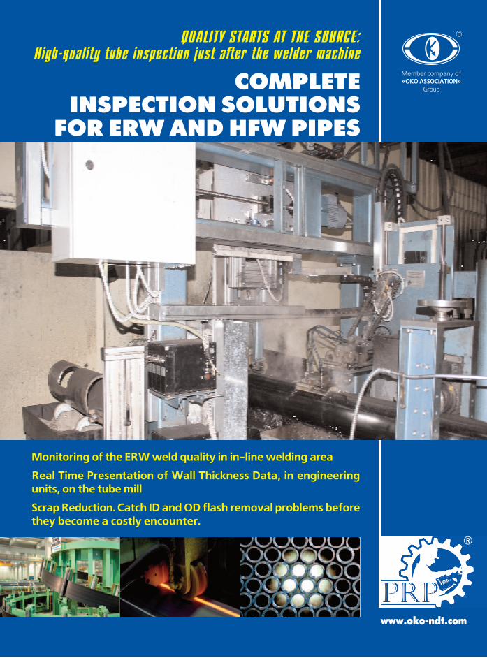
COMPLETEINSPECTION SOLUTIONS
FOR ERW AND HFW PIPES
QUALITY STARTS AT THE SOURCE:High-quality tube inspection just after the welder machine
Monitoring of the ERW weld quality in in-line welding area
Real Time Presentation of Wall Thickness Data, in engineeringunits, on the tube mill
Scrap Reduction. Catch ID and OD flash removal problems beforethey become a costly encounter.
www.oko-ndt.com
®
®
Member company of«OKO ASSOCIATION»
Group
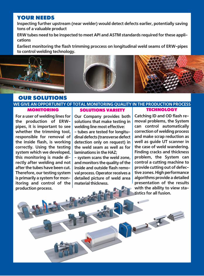
Inspecting further upstream (near welder) would detect defects earlier, potentially savingtons of a valuable productERW tubes need to be inspected to meet API and ASTM standards required for these appli-cations Earliest monitoring the flash trimming proccess on longitudinal weld seams of ERW-pipesto control welding technolog y.
OUR SOLUTIONS
YOUR NEEDS
TECHNOLOGY
Catching ID and OD flash re-moval problems, the Systemcan control automaticallycorrection of welding processand make scrap reduction aswell as guide UT scanner inthe case of weld wandering.Finding cracks and thicknessproblem, the System cancontrol a cutting machine toprovide cutting out of defec-tive zones. High performancealgorithms provide a detailedpresentation of the resultswith the ability to view sta-tistics for all fusion.
MONITORING
For a user of welding lines forthe production of ERW-pipes, it is important to seewhether the trimming tool,responsible for removal ofthe inside flash, is workingcorrectly. Using the testingsystem which we developed,this monitoring is made di-rectly after welding and notafter the tubes have been cut.Therefore, our testing systemis primarily a system for mon-itoring and control of theproduction process.
SOLUTIONS VARIETY
Our Company provides bothsolutions that make testing inwelding line most effective:- tubes are tested for longitu-dinal defects (transverse defectdetection only on request) inthe weld seam as well as forlaminations in the HAZ;- system scans the weld zone,and monitors the quality of theinside and outside flash remo -val process. Operator receives adetailed picture of weld areamaterial thickness.
WE GIVE AN OPPORTUNITY OF TOTAL MONITORING QUALITY IN THE PRODUCTION PROCESS
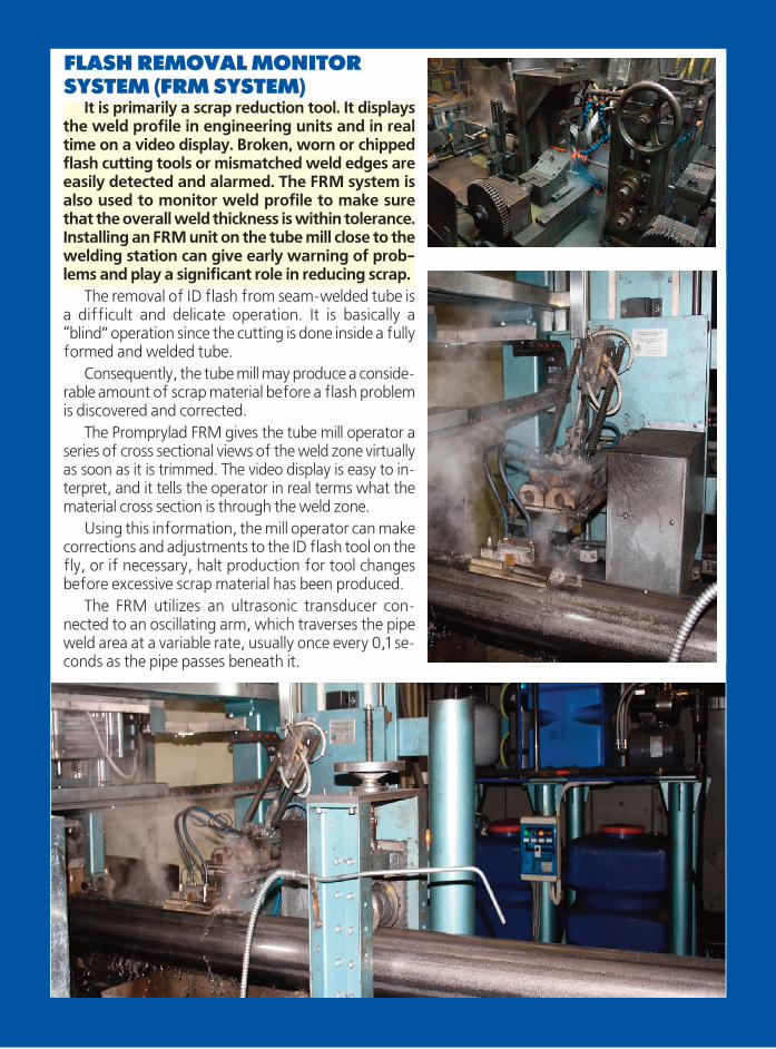
FLASH REMOVAL MONITORSYSTEM (FRM SYSTEM)
It is primarily a scrap reduction tool. It displaysthe weld profile in engineering units and in realtime on a video display. Broken, worn or chippedflash cutting tools or mismatched weld edges areeasily detected and alarmed. The FRM system isalso used to monitor weld profile to make surethat the overall weld thickness is within tolerance.Installing an FRM unit on the tube mill close to thewelding station can give early warning of prob-lems and play a significant role in reducing scrap.
The removal of ID flash from seam-welded tube isa difficult and delicate operation. It is basically a“blind” operation since the cutting is done inside a fullyformed and welded tube.
Consequently, the tube mill may produce a conside -rable amount of scrap material before a flash problemis discovered and corrected.
The Promprylad FRM gives the tube mill ope rator aseries of cross sectional views of the weld zone virtuallyas soon as it is trimmed. The video display is easy to in-terpret, and it tells the operator in real terms what thematerial cross section is through the weld zone.
Using this information, the mill operator can makecorrections and adjustments to the ID flash tool on thefly, or if necessary, halt production for tool changesbefore excessive scrap material has been produced.
The FRM utilizes an ultrasonic transducer con-nected to an oscillating arm, which traverses the pipeweld area at a variable rate, usually once every 0,1 se -conds as the pipe passes beneath it.
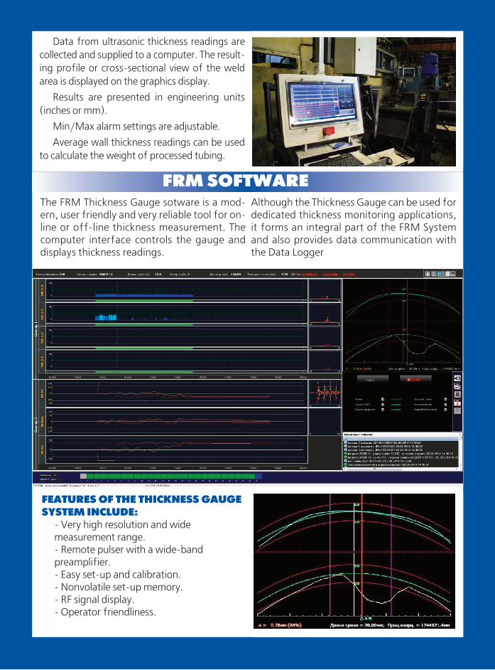
The FRM Thickness Gauge sotware is a mod-ern, user friendly and very reliable tool for on-line or off-line thickness measurement. Thecomputer interface controls the gauge anddisplays thickness readings.
Although the Thickness Gauge can be used fordedicated thickness monitoring applications,it forms an integral part of the FRM Systemand also provides data communication withthe Data Logger
Data from ultrasonic thickness readings arecollected and supplied to a computer. The result-ing profile or cross-sectional view of the weldarea is displayed on the graphics display.
Results are presented in engineering units(inches or mm).
Min/Max alarm settings are adjustable.
Average wall thickness readings can be usedto calculate the weight of processed tubing.
FEATURES OF THE THICKNESS GAUGE SYSTEM INCLUDE:
- Very high resolution and wide measurement range.- Remote pulser with a wide-band preamplifier.- Easy set-up and calibration. - Nonvolatile set-up memory.- RF signal display.- Operator friendliness.
FRM SOFTWARE
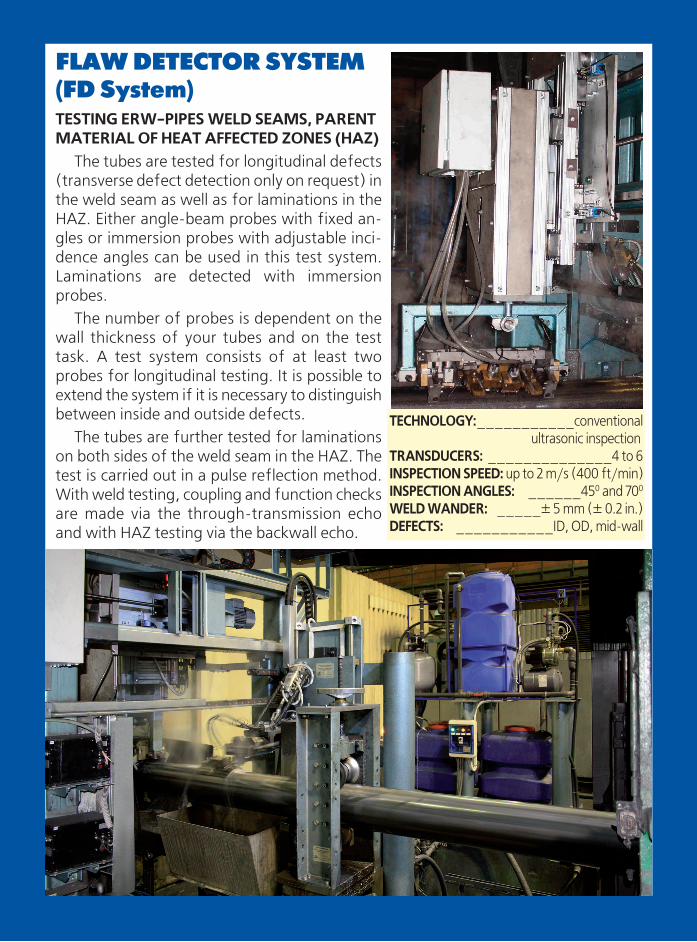
FLAW DETECTOR SYSTEM(FD System)TESTING ERW-PIPES WELD SEAMS, PARENTMATERIAL OF HEAT AFFECTED ZONES (HAZ)
The tubes are tested for longitudinal defects(transverse defect detection only on request) inthe weld seam as well as for laminations in theHAZ. Either angle-beam probes with fixed an-gles or immersion probes with adjustable inci-dence angles can be used in this test system.Laminations are detected with immersionprobes.
The number of probes is dependent on thewall thickness of your tubes and on the testtask. A test system consists of at least twoprobes for longitudinal testing. It is possible toextend the system if it is necessary to distinguishbetween inside and outside defects.
The tubes are further tested for laminationson both sides of the weld seam in the HAZ. Thetest is carried out in a pulse reflection method.With weld testing, coupling and function checksare made via the through-transmission echoand with HAZ testing via the backwall echo.
TECHNOLOGY:___________conventionalultrasonic inspection
TRANSDUCERS: ______________4 to 6INSPECTION SPEED: up to 2 m/s (400 ft/min)INSPECTION ANGLES: ______450 and 700
WELD WANDER: _____± 5 mm (± 0.2 in.)DEFECTS: ___________ID, OD, mid-wall
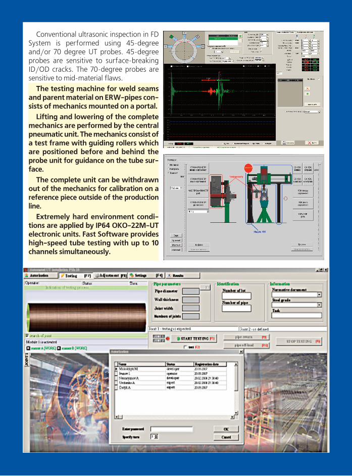
Conventional ultrasonic inspection in FDSystem is performed using 45-degreeand/or 70 degree UT probes. 45-degreeprobes are sensitive to surface-breakingID/OD cracks. The 70-degree probes aresensitive to mid-material flaws.
The testing machine for weld seamsand parent material on ERW-pipes con-sists of mechanics mounted on a portal.
Lifting and lowering of the completеmechanics are performed by the centralpneumatic unit. The mechanics consist ofa test frame with guiding rollers whichare positioned before and behind theprobe unit for guidance on the tube sur-face.
The complete unit can be withdrawnout of the mechanics for calibration on areferen ce piece outside of the productionline.
Extremely hard environment condi-tions are applied by IP64 OKO-22M-UTelectronic units. Fast Software provideshigh-speed tube testing with up to 10channels simultaneously.
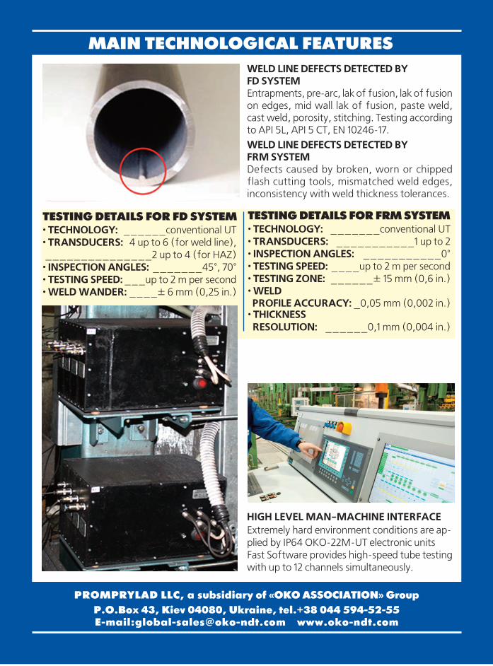
MAIN TECHNOLOGICAL FEATURESWELD LINE DEFECTS DETECTED BY FD SYSTEMEntrapments, pre-arc, lak of fusion, lak of fusionon edges, mid wall lak of fusion, paste weld,cast weld, porosity, stitching. Testing accordingto API 5L, API 5 CT, EN 10246-17.WELD LINE DEFECTS DETECTED BY FRM SYSTEMDefects caused by broken, worn or chippedflash cutting tools, mismatched weld edges,inconsistency with weld thickness tolerances.
TESTING DETAILS FOR FD SYSTEM· TECHNOLOGY: ______conventional UT· TRANSDUCERS: 4 up to 6 (for weld line),_______________2 up to 4 (for HAZ)· INSPECTION ANGLES: _______45°, 70°· TESTING SPEED:___up to 2 m per second· WELD WANDER: ____± 6 mm (0,25 in.)
TESTING DETAILS FOR FRM SYSTEM· TECHNOLOGY: _______conventional UT· TRANSDUCERS: ___________1 up to 2· INSPECTION ANGLES: ___________0°· TESTING SPEED: ____up to 2 m per second· TESTING ZONE: ______± 15 mm (0,6 in.)· WELD PROFILE ACCURACY: _0,05 mm (0,002 in.)
· THICKNESS RESOLUTION: ______0,1 mm (0,004 in.)
PROMPRYLAD LLC, a subsidiary of «OKO ASSOCIATION» Group
P.O.Box 43, Kiev 04080, Ukraine, tel.+38 044 594�52�55E�mail:[email protected] www.oko-ndt.com
HIGH LEVEL MAN-MACHINE INTERFACEExtremely hard environment conditions are ap-plied by IP64 OKO-22M-UT electronic unitsFast Software provides high-speed tube testingwith up to 12 channels simultaneously.


![Proceedings of - Applus+86e60015...could impact weld integrity. -ERW seams are aLF common long seam type for line pipe manufactured from the 1930s through 1970[2]. This welding process](https://img.pdfslide.us/doc/110x75/5e992ec50093ff5d8a1a56d8/proceedings-of-applus-86e60015-could-impact-weld-integrity-erw-seams-are.jpg)