Embed Size (px)
Citation preview

High quality interfaces of InAs-on-insulator field-effect transistors with ZrO2 gatedielectricsKuniharu Takei, Rehan Kapadia, Hui Fang, E. Plis, Sanjay Krishna, and Ali Javey Citation: Applied Physics Letters 102, 153513 (2013); doi: 10.1063/1.4802779 View online: http://dx.doi.org/10.1063/1.4802779 View Table of Contents: http://scitation.aip.org/content/aip/journal/apl/102/15?ver=pdfcov Published by the AIP Publishing Articles you may be interested in ZrO2 and HfO2 dielectrics on (001) n-InAs with atomic-layer-deposited in situ surface treatment Appl. Phys. Lett. 108, 132904 (2016); 10.1063/1.4945430 Scaled ZrO2 dielectrics for In0.53Ga0.47As gate stacks with low interface trap densities Appl. Phys. Lett. 104, 182912 (2014); 10.1063/1.4875977 Effect of indium concentration on InGaAs channel metal-oxide-semiconductor field-effect transistors with atomiclayer deposited gate dielectric J. Vac. Sci. Technol. B 29, 040601 (2011); 10.1116/1.3597199 Electrical properties of InAlN/GaN high electron mobility transistor with Al 2 O 3 , ZrO 2 , and GdScO 3 gatedielectrics J. Vac. Sci. Technol. B 29, 01A808 (2011); 10.1116/1.3521506 Gate-first inversion-type InP metal-oxide-semiconductor field-effect transistors with atomic-layer-deposited Al 2 O3 gate dielectric Appl. Phys. Lett. 92, 233508 (2008); 10.1063/1.2937117
Reuse of AIP Publishing content is subject to the terms at: https://publishing.aip.org/authors/rights-and-permissions. Download to IP: 130.126.153.83 On: Sun, 14 Aug 2016
00:02:35
High quality interfaces of InAs-on-insulator field-effecttransistors with ZrO2 gate dielectrics
Kuniharu Takei,1,2,3 Rehan Kapadia,1,2,3 Hui Fang,1,2,3 E. Plis,4 Sanjay Krishna,4
and Ali Javey1,2,3,a)
1Electrical Engineering and Computer Sciences, University of California, Berkeley, California 94720, USA2Materials Sciences Division, Lawrence Berkeley National Laboratory, Berkeley, California 94720, USA3Berkeley Sensor and Actuator Center, University of California, Berkeley, California 94720, USA4Electrical and Computer Engineering, University of New Mexico, Albuquerque, New Mexico 87106, USA
(Received 24 December 2012; accepted 26 March 2013; published online 19 April 2013)
Interface quality of InAs-on-insulator (XOI) field-effect transistors (FETs) with a ZrO2 gate
dielectric is examined as a function of various chemical treatments. With a forming gas anneal,
InAs XOI FETs exhibit a low subthreshold swing of �72 mV/dec with an interface trap density of
�1.5� 1012 states/cm2 eV—both of which are comparable to the best reported epitaxially grown
III-V devices on III-V substrates. Importantly, the results indicate that the surface properties of
InAs are preserved during the layer transfer process, thereby, enabling the realization of high
performance III-V FETs on Si substrates using the XOI configuration. VC 2013 AIP Publishing LLC[http://dx.doi.org/10.1063/1.4802779]
III-V compound semiconductors present a promising
class of materials for future low-power and high-speed elec-
tronics due to their low carrier effective mass and high
mobilities.1–3 Two promising approaches have been explored
for integration of III-V semiconductors on Si wafers: (i) direct
epitaxial growth on Si using buffer layers4 and (ii) selective
layer transfer from an epitaxial growth substrate onto a Si/
SiO2 substrate.5,6 The latter approach results in III-V on insu-
lator (XOI) structures and presents the advantage of removing
lattice mismatch constraints associated with the growth sub-
strate. To date, high electron mobility InAs and InAsSb field-
effect transistors (FETs);7,8 high hole mobility InGaSb FETs;9
and III-V complementary-FETs10 have been demonstrated on
Si substrates by using the XOI scheme. Despite these recent
advancements, the dielectric and III-V interface quality is still
largely unknown, and it remains a question whether similar
interface qualities to direct epitaxial growth processes11 can
be obtained in XOI devices. Here, we focus on answering this
question for InAs XOI FETs with ZrO2 gate dielectrics by
examining the effect of various chemical treatments on the
interface properties. Specifically, the subthreshold swing (SS)
and interface trap density (Dit) are systematically character-
ized by current-voltage (I-VG), capacitance-voltage (C-VG),
and conductance-frequency (G/x-f) measurements. The long-
channel devices treated under the optimal condition exhibit a
SS as low as �72 mV/decade and Dit of �1.5� 1012 states/
cm�2 eV, both of which are comparable to the best values
reported for the epi-grown and/or bulk III-V devices.11 The
results demonstrate that high quality interfaces can be
obtained in layer transferred InAs XOI structures, which is of
fundamental importance for the practice use of this technol-
ogy for future scaled transistors.
Ultrathin (�10 nm-thick) InAs films grown by a molecu-
lar beam epitaxy (MBE) on GaSb substrates with an AlGaSb
sacrificial layer were transferred onto thermally grown SiO2
(1.6 lm thick) on pþSi substrates using a previously
described process.5 Before transferring the InAs film to the
Si/SiO2 substrate, the back surface of the lifted-off InAs was
cleaned with 1% HF in water to remove AlGaSb residues.
After transferring the film onto the Si/SiO2 substrate, the top
surface of the InAs was cleaned with hot acetone at �60 �Cto remove organic residues. Due to InAs native oxide forma-
tion during the fabrication process, the final thickness of
InAs is �8 nm as confirmed by transmission electron micros-
copy. Ni source (S) and drain (D) electrodes were patterned,
followed by contact annealing at 300 �C for 1 min in N2 to
obtain low contact resistances (�200-300 X lm) as previ-
ously reported.12 A 10 nm-thick ZrO2 film was deposited as
the gate dielectric by atomic layer deposition (ALD) at
130 �C using tetrakis (ethylmethylamido) zirconium and
water precursors. After ZrO2 deposition, various thermal
annealing and plasma treatments were performed, followed
by an examination of the effect on the interface quality
between InAs and ZrO2 (i.e., top interface), InAs and SiO2
(i.e., bottom interface), and the trap density in ZrO2. The
post-ALD thermal annealing was performed in either 5% H2
in N2 or 200 ppm H2S in N2 for 30 min at 170 �C under
atmospheric pressure. This temperature was chosen since
thermal annealing at >170 �C resulted in noticeable degrada-
tion of InAs device properties (including SS) for both gas
environments. No change in the contact resistance is
observed after this step. In addition, samples exposed to CF4/
O2 plasma (120 sccm CF4, 10 sccm O2, 30 W, 3 min)11 after
ZrO2 deposition were prepared and characterized. In addition
to the above treatments, InAs XOI FETs with thermally
grown oxide using 2% O2 in Ar at 350 �C for 1 min before
ZrO2 deposition were prepared. Prior to the thermal oxida-
tion, InAs native oxide was etched by 3% NH4OH in water.
Our previous studies5 have shown the thermal oxide of InAs
to improve the SS of XOI FETs as compared to untreated
samples and those with etched interfacial native oxide.
After the various surface/interface treatments, Ni/Au
gate (G) electrodes were patterned and ZrO2 over the contact
a)Author to whom correspondence should be addressed. Electronic mail:
0003-6951/2013/102(15)/153513/4/$30.00 VC 2013 AIP Publishing LLC102, 153513-1
APPLIED PHYSICS LETTERS 102, 153513 (2013)
Reuse of AIP Publishing content is subject to the terms at: https://publishing.aip.org/authors/rights-and-permissions. Download to IP: 130.126.153.83 On: Sun, 14 Aug 2016
00:02:35
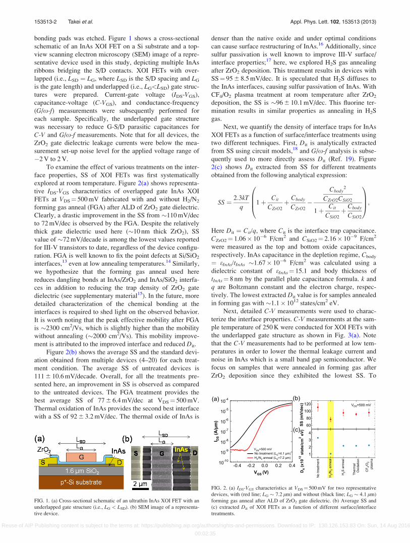
bonding pads was etched. Figure 1 shows a cross-sectional
schematic of an InAs XOI FET on a Si substrate and a top-
view scanning electron microscopy (SEM) image of a repre-
sentative device used in this study, depicting multiple InAs
ribbons bridging the S/D contacts. XOI FETs with over-
lapped (i.e., LSD ¼ LG, where LSD is the S/D spacing and LG
is the gate length) and underlapped (i.e., LG<LSD) gate struc-
tures were prepared. Current-gate voltage (IDS-VGS),
capacitance-voltage (C-VGS), and conductance-frequency
(G/x-f) measurements were subsequently performed for
each sample. Specifically, the underlapped gate structure
was necessary to reduce G-S/D parasitic capacitances for
C-V and G/x-f measurements. Note that for all devices, the
ZrO2 gate dielectric leakage currents were below the mea-
surement set-up noise level for the applied voltage range of
�2 V to 2 V.
To examine the effect of various treatments on the inter-
face properties, SS of XOI FETs was first systematically
explored at room temperature. Figure 2(a) shows representa-
tive IDS-VGS characteristics of overlapped gate InAs XOI
FETs at VDS¼ 500 mV fabricated with and without H2/N2
forming gas anneal (FGA) after ALD of ZrO2 gate dielectric.
Clearly, a drastic improvement in the SS from �110 mV/dec
to 72 mV/dec is observed by the FGA. Despite the relatively
thick gate dielectric used here (�10 nm thick ZrO2), SS
value of �72 mV/decade is among the lowest values reported
for III-V transistors to date, regardless of the device configu-
ration. FGA is well known to fix the point defects at Si/SiO2
interfaces,13 even at low annealing temperatures.14 Similarly,
we hypothesize that the forming gas anneal used here
reduces dangling bonds at InAs/ZrO2 and InAs/SiO2 interfa-
ces in addition to reducing the trap density of ZrO2 gate
dielectric (see supplementary material15). In the future, more
detailed characterization of the chemical bonding at the
interfaces is required to shed light on the observed behavior.
It is worth noting that the peak effective mobility after FGA
is �2300 cm2/Vs, which is slightly higher than the mobility
without annealing (�2000 cm2/Vs). This mobility improve-
ment is attributed to the improved interface and reduced Dit.
Figure 2(b) shows the average SS and the standard devi-
ation obtained from multiple devices (4–20) for each treat-
ment condition. The average SS of untreated devices is
111 6 10.6 mV/decade. Overall, for all the treatments pre-
sented here, an improvement in SS is observed as compared
to the untreated devices. The FGA treatment provides the
best average SS of 77 6 6.4 mV/dec at VDS¼ 500 mV.
Thermal oxidation of InAs provides the second best interface
with a SS of 92 6 3.2 mV/dec. The thermal oxide of InAs is
denser than the native oxide and under optimal conditions
can cause surface restructuring of InAs.16 Additionally, since
sulfur passivation is well known to improve III-V surface/
interface properties;17 here, we explored H2S gas annealing
after ZrO2 deposition. This treatment results in devices with
SS¼ 95 6 8.5 mV/dec. It is speculated that H2S diffuses to
the InAs interfaces, causing sulfur passivation of InAs. With
CF4/O2 plasma treatment at room temperature after ZrO2
deposition, the SS is �96 6 10.1 mV/dec. This fluorine ter-
mination results in similar properties as annealing in H2S
gas.
Next, we quantify the density of interface traps for InAs
XOI FETs as a function of surface/interface treatments using
two different techniques. First, Dit is analytically extracted
from SS using circuit models,18 and G/x-f analysis is subse-
quently used to more directly assess Dit (Ref. 19). Figure
2(c) shows Dit extracted from SS for different treatments
obtained from the following analytical expression:
SS ¼ 2:3kT
q1þ Cit
CZrO2
þ Cbody
CZrO2
�
Cbody2
CZrO2CSiO2
1þ Cit
CSiO2
þ Cbody
CSiO2
0BB@
1CCA;
Here Dit ¼ Cit/q, where Cit is the interface trap capacitance.
CZrO2¼ 1.06� 10�6 F/cm2 and CSiO2¼ 2.16� 10�9 F/cm2
were measured as the top and bottom oxide capacitances,
respectively. InAs capacitance in the depletion regime, Cbody
¼ eInAs/tInAs �1.67� 10�6 F/cm2 was calculated using a
dielectric constant of eInAs¼ 15.1 and body thickness of
tInAs¼ 8 nm by the parallel plate capacitance formula. k and
q are Boltzmann constant and the electron charge, respec-
tively. The lowest extracted Dit value is for samples annealed
in forming gas with �1.1� 1012 states/cm2 eV.
Next, detailed C-V measurements were used to charac-
terize the interface properties. C-V measurements at the sam-
ple temperature of 250 K were conducted for XOI FETs with
the underlapped gate structure as shown in Fig. 3(a). Note
that the C-V measurements had to be performed at low tem-
peratures in order to lower the thermal leakage current and
noise in InAs which is a small band gap semiconductor. We
focus on samples that were annealed in forming gas after
ZrO2 deposition since they exhibited the lowest SS. To
FIG. 1. (a) Cross-sectional schematic of an ultrathin InAs XOI FET with an
underlapped gate structure (i.e., LG < LSD). (b) SEM image of a representa-
tive device.
FIG. 2. (a) IDS-VGS characteristics at VDS¼ 500 mV for two representative
devices, with (red line; LG � 7.2 lm) and without (black line; LG � 4.1 lm)
forming gas anneal after ALD of ZrO2 gate dielectric. (b) Average SS and
(c) extracted Dit of XOI FETs as a function of different surface/interface
treatments.
153513-2 Takei et al. Appl. Phys. Lett. 102, 153513 (2013)
Reuse of AIP Publishing content is subject to the terms at: https://publishing.aip.org/authors/rights-and-permissions. Download to IP: 130.126.153.83 On: Sun, 14 Aug 2016
00:02:35
reduce parasitic resistances from un-gated InAs channel
region, global back-gate bias of 40 V is applied to pþSi sub-
strate during both C-V and G/x-f measurements shown in
Figs. 3 and 4 (see supplementary material15). Gate capaci-
tance, CG, was obtained from the accumulation region of
C-V curves at VG¼ 1.5 V to be 0.73 lF/cm2 (Figure 3(b)).
CG consists of stack layers of ZrO2 dielectric capacitance
CZrO2, InAs charge centroid capacitance Ccentroid, and den-
sity of state (DOS) quantum capacitance CQ-DOS calculated
by using the equation previously reported.9 From our previ-
ous study,12 the electron charge centroid of 8 nm InAs is
tcentroid� 3.2 nm from the top surface (at VG�1.5 V), giving
Ccentroid ¼ eInAs/tcentroid � 4.18� 10�6 F/cm2. The total ca-
pacitance, 1/CG¼ 1/Cox þ 1/Ccentroid þ 1/CQ-DOS is calcu-
lated to be �6.1� 10�7 F/cm2, where Cox¼CZrO2 ¼ 1.06
� 10�6 F/cm2 and CQ-DOS¼ 2.17� 10�6 F/cm2. The calcu-
lated CG value matches with the experimental value (Fig.
3(b)). In the inversion region at VG < �0.5 V, a large fre-
quency dispersion of capacitance is observed. This trend is
due to the lack of minority carrier (i.e., holes) response at
high frequencies. The observed inversion behavior is similar
to a conventional MOS capacitor. Note that unlike conven-
tional MOSFETs, our XOI FETs consist of an n-channel
body with ohmic metal S/D contacts to the conduction band
of InAs. While there are no Schottky barrier heights for elec-
trons, the Schottky barrier height for holes is nearly the full
band gap. Thereby, S/D contacts do not provide significant
hole injection into the channel. This structural difference
causes the observed frequency dispersion in the inversion
regime.
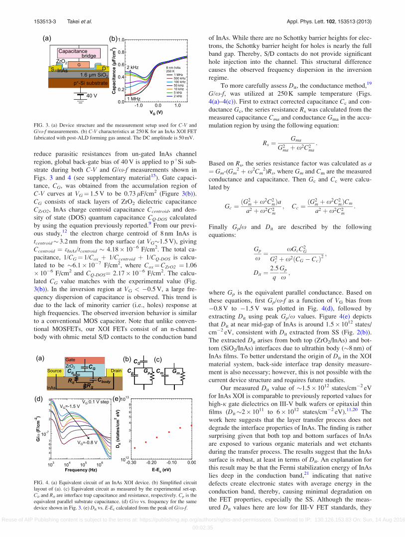
To more carefully assess Dit, the conductance method,19
G/x-f, was utilized at 250 K sample temperature (Figs.
4(a)–4(c)). First to extract corrected capacitance Cc and con-
ductance Gc, the series resistance Rs was calculated from the
measured capacitance Cma and conductance Gma in the accu-
mulation region by using the following equation:
Rs ¼Gma
G2ma þ x2C2
ma
:
Based on Rs, the series resistance factor was calculated as a¼ Gm-(Gm
2 þ x2Cm2)Rs, where Gm and Cm are the measured
conductance and capacitance. Then Gc and Cc were calcu-
lated by
Gc ¼ðG2
m þ x2C2mÞa
a2 þ x2C2m
; Cc ¼ðG2
m þ x2C2mÞCm
a2 þ x2C2m
:
Finally Gp/x and Dit are described by the following
equations:
Gp
x¼ xGcC2
G
G2c þ x2ðCG � CcÞ2
;
Dit ¼2:5
q
Gp
x;
where Gp is the equivalent parallel conductance. Based on
these equations, first Gp/x-f as a function of VG bias from
�0.8 V to �1.5 V was plotted in Fig. 4(d), followed by
extracting Dit using peak Gp/x values. Figure 4(e) depicts
that Dit at near mid-gap of InAs is around 1.5� 1012 states/
cm�2 eV, consistent with Dit extracted from SS (Fig. 2(b)).
The extracted Dit arises from both top (ZrO2/InAs) and bot-
tom (SiO2/InAs) interfaces due to ultrathin body (�8 nm) of
InAs films. To better understand the origin of Dit in the XOI
material system, back-side interface trap density measure-
ment is also necessary; however, this is not possible with the
current device structure and requires future studies.
Our measured Dit value of �1.5� 1012 states/cm�2 eV
for InAs XOI is comparable to previously reported values for
high-j gate dielectrics on III-V bulk wafers or epitaxial thin
films (Dit�2� 1011 to 6� 1012 states/cm�2 eV).11,20 The
work here suggests that the layer transfer process does not
degrade the interface properties of InAs. The finding is rather
surprising given that both top and bottom surfaces of InAs
are exposed to various organic materials and wet etchants
during the transfer process. The results suggest that the InAs
surface is robust, at least in terms of Dit. An explanation for
this result may be that the Fermi stabilization energy of InAs
lies deep in the conduction band,21 indicating that native
defects create electronic states with average energy in the
conduction band, thereby, causing minimal degradation on
the FET properties, especially the SS. Although the meas-
ured Dit values here are low for III-V FET standards, they
FIG. 3. (a) Device structure and the measurement setup used for C-V and
G/x-f measurements. (b) C-V characteristics at 250 K for an InAs XOI FET
fabricated with post-ALD forming gas anneal. The DC amplitude is 50 mV.
FIG. 4. (a) Equivalent circuit of an InAs XOI device. (b) Simplified circuit
layout of (a). (c) Equivalent circuit as measured by the experimental set-up.
Cit and Rit are interface trap capacitance and resistance, respectively. Cp is the
equivalent parallel substrate capacitance. (d) G/x vs. frequency for the same
device shown in Fig. 3. (e) Dit vs. E-Ec calculated from the peak of G/x-f.
153513-3 Takei et al. Appl. Phys. Lett. 102, 153513 (2013)
Reuse of AIP Publishing content is subject to the terms at: https://publishing.aip.org/authors/rights-and-permissions. Download to IP: 130.126.153.83 On: Sun, 14 Aug 2016
00:02:35
are still large compared to Si devices. However, our lowest
SS is �72 mV/decade, which is close to the MOSFET ideal
limit, despite the relatively thick gate dielectric used here. In
the future, SS can be further improved by using a thinner top
gate dielectric.
In summary, through subthreshold swing analyses, and
C-V and G/x-f measurements, the surface/interface proper-
ties of InAs XOI FETs on Si substrates are characterized as a
function of various treatments. It is found that FGA after the
deposition of the ZrO2 gate dielectric significantly improves
SS of XOI FETs, with the lowest value of �72 mV/dec,
which is close to the theoretical limit of �60 mV/decade.
The Dit value was extracted to be �1.5� 1012 states/
cm�2 eV near the mid-gap of InAs. These results indicate
that the overall quality of InAs surfaces is preserved during
the layer transfer process.
This work was funded by NSF E3S Center and Intel.
The materials characterization part of this work was partially
supported by the Director, Office of Science, Office of Basic
Energy Sciences, and Division of Materials Sciences and
Engineering of the U.S. Department of Energy under
Contract No. De-Ac02-05Ch11231. A.J. acknowledges sup-
port from the World Class University program at Sunchon
National University. K.T. acknowledges funding from NSF
COINS. S.K. acknowledges support from AFOSR FA9550-
10-1-0113 and FA9550-09-1-0231.
1D.-H. Kim and J. A. del Alamo, IEEE Trans. Electron Devices 57, 1504
(2010).2J. A. del Alamo, Nature (London) 479, 317 (2011).3M. Heyns and W. Tsai, MRS Bull. 34, 485 (2009).4M. Radosavljevic, B. Chu-Kung, S. Corcoran, G. Dewey, M. K. Hudait, J.
M. Fastenau, J. Kavalieros, W. K. Liu, D. Lubyshev, M. Metz, K. Millard,
N. Mukherjee, W. Rachmady, UShah, and R. Chau, Tech. Dig. – Int.
Electron Devices Meet. 2009, 319.5H. Ko, K. Takei, R. Kapadia, S. Chuang, H. Fang, P. W. Leu, K.
Ganapathi, E. Phis, H. S. Kim, S.-Y. Chen, M. Madsen, A. C. Ford, Y.-L.
Chueh, S. Krishna, S. Salahuddin, and A. Javey, Nature (London) 468,
286 (2010).6M. Yokoyama, T. Yasuda, H. Takagi, N. Miyata, Y. Urabe, H. Ishii, H.
Yamada, N. Furuhara, M. Hata, M. Sugiyama, Y. Nakano, M. Takenaka,
and S. Takagi, Appl. Phys. Lett. 96, 142106 (2010).7K. Takei, S. Chuang, H. Fang, R. Kapadia, C.-H. Liu, J. Nah, H. S. Kim,
E. Plis, S. Krishna, Y.-L. Chueh, and A. Javey, Appl. Phys. Lett. 99,
103507 (2011).8H. Fang, S. Chuang, K. Takei, H. S. Kim, E. Plis, C.-H. Liu, S. Krishna,
Y.-L. Chueh, and A. Javey, IEEE Electron Device Lett. 33, 504 (2012).9K. Takei, M. Madsen, H. Fang, R. Kapadia, S. Chuang, H. S. Kim, C.-H.
Liu, E. Plis, J. Nah, S. Krishna, Y.-L. Chueh, J. Guo, and A. Javey, Nano
Lett. 12, 2060 (2012).10J. Nah, H. Fang, C. Wang, K. Takei, M. H. Lee, E. Plis, S. Krishna, and A.
Javey, Nano Lett. 12, 3592 (2012).11Y.-T. Chen, Y. Wang, F. Xue, F. Zhou, and J. C. Lee, IEEE Trans.
Electron Devices 59, 139 (2012).12K. Takei, H. Fang, S. B. Kumar, R. Kapadia, Q. Gao, M. Madsen, H. S.
Kim, C.-H. Liu, Y.-L. Chueh, E. Plis, S. Krishna, H. A. Bechtel, J. Guo,
and A. Javey, Nano Lett. 11, 5008 (2011).13A. Stesmans and V. V. Afanas’ev, Phys. Rev. B 57, 10030 (1998).14L. Do Thanh and P. Balk, J. Electrochem. Soc. 135, 1797 (1988).15See supplementary material at http://dx.doi.org/10.1063/1.4802779 for
back-gate dependence of the devices and the effect of the forming gas
annealing on ZrO2 film quality.16M. P. J. Punkkinen, P. Laukkanen, J. Lang, M. Kuzmin, M. Tuominen,
V. Tuominen, J. Dahl, M. Pessa, M. Guina, K. Kokko, J. Sadowski, B.
Johansson, I. J. Vayrynen, and L. Vitos, Phys. Rev. B 83, 195329
(2011).17E. O’Connor, B. Brennan, V. Djara, K. Cherkaoui, S. Monaghan, S. B.
Newcomb, R. Contreras, M. Milojevic, G. Hughes, M. E. Pemble, R. M.
Wallace, and P. K. Hurley, J. Appl. Phys. 109, 024101 (2011).18J. P. Colinge, D. Flandre, and F. Van de Wiele, Solid-State Electron. 37,
289 (1994).19E. H. Nicollian and A. Goetzberger, Appl. Phys. Lett. 10, 60 (1967).20Y. Hwang, V. Chobpattana, J. Y. Zhang, J. M. LeBeau, R. Engel-Herbert,
and S. Stemmer, Appl. Phys. Lett. 98, 142901 (2011).21W. Walukiewicz, Physica B 302–303, 123 (2001).
153513-4 Takei et al. Appl. Phys. Lett. 102, 153513 (2013)
Reuse of AIP Publishing content is subject to the terms at: https://publishing.aip.org/authors/rights-and-permissions. Download to IP: 130.126.153.83 On: Sun, 14 Aug 2016
00:02:35


![INAS 342 - the Flying Sentinels [Indian Navy]](https://img.pdfslide.us/doc/110x75/577d1cf51a28ab4e1e8b4993/inas-342-the-flying-sentinels-indian-navy.jpg)