Embed Size (px)
Citation preview

www.andritz.com/pumps
High-pressure pumpsSeries HP43


3
Description / ApplicationMulti-stage high pressure pumps for water supply, irrigation and
industrial applications, for hot and cold water circulation, fire fight-
ing, boiler feed and pressure boosting installations. Suitable for
all clean or slightly dirty non-corrosive liquids up to a viscosity of
150 mm²/s (cSt).
Operating range
Nominal branch diameter DN 40-200
Capacity Q up to 850 m3/h
Head H up to 630 m
Operating pressure p up to 63 bar
Liquid temperature t -20°C up to +140°C
Speed n up to 3600 rpm
DesignationHP 100-240.1/5/E + 22/4
Nominal branch diameter [mm]
Nominal impeller diameter [mm]
Hydraulics ID
Nominal power P2 [kW]
Number of poles
Series
Number of stages
Arrangement
Example
General
Product advantages
� Numerous horizontal and vertical models for an efficient buil-
ding design.
� Flexible arrangement of suction- and delivery branch.
� Numerous hydraulic units per model size guarantee a design
at the optimal operating point.
� High efficiencies owing to optimized hydraulics.
� Optimal adaptability to the medium to be pumped owing to a
variety of material and sealing versions.
� Pump shaft protected along its entire length by means of
impeller hubs and sleeves.
� Balancing of the axial thrust by means of balancing piston (at
high pressure).

4
Arrangements
Arrangement A1 and E1
Pump arranged horizontally. Radial suction and delivery connec-
tions. On the suction and delivery sides, shaft mounted in grease
lubricated ball bearings outside the pump body. Drive on suction
side with anti-clockwise rotation, seen from drive end. Pump and
motor mounted on a common base plate, connectec by a flexible
coupling.
Arrangement A2 and E2
Pump arranged horizontally. Radial suction and delivery connec-
tions. On delivery side, shaft mounted outside the pump body
in grease lubricated ball bearings, and on suction side rotating
in a sleeve bearing lubricated by the pumped medium. Drive on
delivery side with clockwise rotation, seen from drive end. Pump
and motor mounted on a common base plate, connectec by a
flexible coupling.
Arrangement A3 and E3
Pump arranged horizontally. Radial suction and delivery connec-
tions. On the suction and delivery sides, shaft mounted in grease
lubricated ball bearings outside the pump body. Drive on delivery
side with clockwise rotation, seen from drive end. Pump and mo-
tor mounted on a common base plate, connectec by a flexible
coupling.
Arrangement AX
Pump arranged horizontally. Axial suction connection, radial de-
livery connection. On delivery side, shaft mounted outside the
pump body in grease lubricated ball bearings, and on suction
side rotating in a sleeve bearing situated within the suction bran-
ch lubricated by the pumped medium. Drive on delivery side with
clockwise rotation, seen from drive end. Pump and motor moun-
ted on a common base plate, connectec by a flexible coupling.
Particularly favourable flow pattern towards the first stage impeller
and consequently better suction performance.
Arrangement SPump arranged vertically. Radial suction and
delivery connections. On the suction side, shaft
mounted in a sleeve bearing lubricated by the
pumped medium, and on the delivery side
mounted in grease lubricated ball bearings.
Drive on delivery side with clockwise rotation,
seen from drive end. Pump and motor connec-
ted via a flexible coupling. Particulary space-
saving, easy-to-install design.

5
ConstuctionMulti-stage ring section pump of robust construction with extra
large shaft section for vibration-free running. For high output pres-
sures additional axial thrust balancing is provided by a balancing
piston mounted on pump shaft. All wearing parts are renewable
without additional work on the casing parts. Shaft sealing either
with mechanical seal or gland packing. Bearing housings are pro-
tected against the ingress of spray water by means of lip seals.
Under difficult suction conditions (low NPSH-available), the pump
can be provided with an axial inlet for cavitation-reducing flow
entry pattern into the first stage impeller.
ImpellersAt least two types of impellers with matching diffuser are available
for each pump frame. Therefore operation within the range of op-
timum efficiency is possible for the required output conditions. If
an abrasive medium is being pumped, the slip face and hub sec-
tion of the impeller can be protected by renewable rings / bushes
in wear resistant materials.
Shaft and bearingsIn all the pumps the shaft is protected against wear and corrosion
over its entire length by shaft wear sleeves, especially in the area
of the shaft seal (mechanical seal or gland packing) and the sleeve
bearings in arrangement AX and S. In case of pumps in arrange-
ment A1 and A3, the shaft is mounted outside the pump body in
grease lubricated ball bearings (a radial deep groove ball bearing
on the suction side and a fixed bearing with paired angular con-
tact ball bearings on the delivery side).
On arrangement A2, AX and S, the shaft is carried in a shielded
sleeve bearing lubricated by the pumped medium on the suction
side and, on the delivery side, by grease lubricated angular con-
tact ball bearings. All rolling bearings are protected by lip seals.
Shaft sealingIn the standard version the shaft is sealed by mechanical seal acc.
to DIN 24960. A shaft sealing by gland packing is available as an
option. The packing rings form a seal with a renewable shaft slee-
ve which protects the shaft against wear.
According to requirements following mechanical seals may be
used: � single acting unbalanced mechanical seal � single acting balanced mechanical seal � cartridge seal
Mechanical seals are always mounted on a shaft wear sleeve in
stainless steel.
Axial thrust compensationIn pumps with a small number of stages the ball bearings (fixed
bearings) absorb the axial thrust. In pumps with a larger number
of stages, the axial thrust is equalised by means of a balancing
piston mounted on the shaft in the area of the delivery housing.
Slip facesIn order to prevent wear in the slip face and hub area as far as
possible interchangeable wear-resisting casing rings and neck
bushes are fitted in the housing. The slip faces of the impellers
can also be protected by renewable slip rings.
CouplingConnection between pump and IEC standard motor by flexible
coupling N-Eupex, type B.
Drive � In case of horizontal arrangement by IEC standard motor in
form B3 with supporting feet. � In case of vertical arrangement by IEC standard motor in form
V1, with flange connection according to DIN 42948.
Technical details

6
Branch positionArrangement A1 and E1, horizontal (standard)
� Drive at suction side. � Rotation direction of pump shaft is anti-clockwise, seen from
drive end. � Branch position by standard arrangement L3/0. � Suction and delivery branch to same direction is possible from
3 stages or more.
L3/0 L3/3 L3/9* L9/0 L9/3*
L9/9 L0/0* L0/3 L0/9
* possible from 3 stages
Arrangement A2, E2, A3 and E3, horizontal � Drive at delivery side. � Rotation direction of pump shaft is clockwise, seen from drive
end. � Branch position by standard arrangement R3/0. � Suction and delivery branch to same direction is possible from
3 stages or more.
R3/0 R3/3 R3/9* R9/0 R9/3*
R9/9 R0/0* R0/3 R0/9
* possible from 3 stages
Arrangement AX, horizontal � Drive at delivery side. � Rotation direction of pump shaft is clockwise, seen from drive
end. � Branch position by standard arrangement R4/0.
R4/0 R4/3 R4/9
Arrangement S, vertical � Drive at delivery side. � Rotation direction of pump shaft is clockwise, seen from drive
end. � Branch position by standard arrangement R9/3. � Suction and delivery branch to same direction is possible from
3 stages or more.
R9/3 R9/6 R9/0 R9/9*
* possible from 3 stages
Technical details

7
Selection chart
This chart allows a provisional selection of the pump type most
suitable for a given set of operating conditions. In certain cases
it may be possible to use the next smaller pump type and this
possibility should be included in the final selection. For an exact
pump selection our individual characteristic curves as well as our
pump selection software WinPump are available.
40
5
6
8
10
20
30
40
50
60
80
100
200
300
400
[l/s]
[Imp.gpm]
[US.gpm]
[ft]
20
30
40
50
60
80
100
200
300
400
500
600
800
1000
[m]
20 30 40 50 60 80 100
50 60 80 100 200 300 400 500 600
300 400 500 600 800 1000 2000
300 400 500 600 800 1000 2000
[m³/h]
Speed 1150 rpm
40
5
6
8
10
20
30
40
50
60
80
100
200
300
400
[l/s]
[Imp.gpm]
[US.gpm]
[ft]
20
30
40
50
60
80
100
200
300
400
500
600
800
1000
[m]
20 30 40 50 60 80 100
50 60 80 100 200 300 400 500 600[m³/h]
300 400 500 600 800 1000 2000
300 400 500 600 800 1000 2000
Speed 980 rpm
50Hz
60Hz

8
Selection chart
This chart allows a provisional selection of the pump type most
suitable for a given set of operating conditions. In certain cases
it may be possible to use the next smaller pump type and this
possibility should be included in the final selection. For an exact
pump selection our individual characteristic curves as well as our
pump selection software WinPump are available.
10
5
6
8
10
20
30
40
50
60
80
100
200
300
400
500
600
[l/s] 4
[Imp.gpm]
[US.gpm]
[ft]
20
30
40
50
60
80
100
200
300
400
500
600
800
1000
5 6 8 10 20 30 40 50 60 80 100 200
20 30 40 50 60 80 100 200 300 400 500 600 800[m³/h]
80 100 200 300 400 500 600 800 1000 2000 3000
80 100 200 300 400 500 600 800 1000 2000
[m]
Speed 1760 rpm
5
6
8
10
20
30
40
50
60
80
100
200
300
400
500
[Imp.gpm] 50
[US.gpm] 60
[ft]
20
30
40
50
60
80
100
200
300
400
500
600
800
1000
[l/s] 5 303 4 20 50406 108 60 80 100
8 10 20 30 50 100 200 300 400 600[m³/h]
60 80 100 200 300 400 500 600 800 1000 2000
80 100 200 300 400 500 600 800 1000 2000
[m]
40 60 80
Speed 1450 rpm
50Hz
60Hz

9
Selection chart
This chart allows a provisional selection of the pump type most
suitable for a given set of operating conditions. In certain cases
it may be possible to use the next smaller pump type and this
possibility should be included in the final selection. For an exact
pump selection our individual characteristic curves as well as our
pump selection software WinPump are available.
20
30
40
50
60
70
80
90100
200
300
400
500
600
[l/s]
[Imp.gpm]
[US.gpm]
[ft]
200
300
400
500
600
700
800
9001000
10 20 30 40 50 60 80 100 2008
30 40 50 60 80 100 200 300 400 500 800600[m³/h]
[m]
200 300 400 500 600 800 1000 2000 3000
200 300 400 500 600 800 1000 2000 3000
Speed 3600 rpm
20
20
30
40
50
60
70
8090
100
200
300
400
500
600
[l/s]
[Imp.gpm]
[US.gpm]
[ft]
80
100
200
300
400
500
600
800
1000
10 20 30 40 50 60 80 100 2006 8
30 40 50 60 80 100 200 300 400 500 600 800[m³/h]
[m]
100 200 300 400 500 600 800 1000 2000 3000
100 200 300 400 500 600 1000800 2000
Speed 2950 rpm
50Hz
60Hz
10
Performance curveType 40-160.1
Notes to performance curves � Curves valid according to DIN EN ISO 9906/2B. � Power data refers to clean water, density 1 kg/dm³, viscosity 1 mm²/s. � All duty points between the individual stage characteristics can be achieved by adapting the impeller diameters.
0
1
0
10
20
30
40
50
60
70
80
0
.5
1
1.5
0
0
0 3 4 5 6 7 8 9 10 11 12 13 14 15 16 17 18
0 1 1.5 2 2.5 3 3.5 4 4.5 5
P[kW]
ETA[%]
NPSH
[m] [ft]
Q m /h
Q l/s
Q m /min
3
3
0
15
30
45
60
75
90
105
120
135
150
0
75
150
225
300
375
450
0 15 20 25 30 35 40 45 50 55 60 65 70 75 80
0 15 20 25 30 35 40 45 50 55 60 65
0 3 4 5 6 7 8 9 10 11 12 13 14 15 16 17 18
0 1 1.5 2 2.5 3 3.5 4 4.5 5
H[m]
H[ft]
U.S.gpm
Imp.g.p.m.
Q m /h
Q l/s
3
13
12
11
10
09
08
07
06
05
04
03
02
01
14
15
16
0
2
4
0
10
20
30
40
50
60
70
80
0
1
2
3
0
5
0
0 10 15 20 25 30 35 40
0 2.5 5 7.5 10
P[kW]
ETA[%]
NPSH
[m] [ft]
Q m /h
Q l/s
Q m /min
3
3
0
25
50
75
100
125
150
175
200
225
250
275
300
325
350
375
400
425
450
475
500
525
550
0
125
250
375
500
625
750
875
1000
1125
1250
1375
1500
1625
1750
0 50 75 100 125 150 175
0 25 50 75 100 125
0 10 15 20 25 30 35 40
0 2.5 5 7.5 10
H[m]
H[ft]
U.S.gpm
Imp.g.p.m.
Q m /h
Q l/s
3
13
12
11
10
09
08
07
06
05
04
03
02
01
14
15
16
Speed 1450 rpm Speed 2950 rpm
65917 65919
50Hz

11
Performance curveType 40-160.2
0
15
30
45
60
75
90
105
120
135
0
75
150
225
300
375
0 20 30 40 50 60 70 80 90 100
0 20 30 40 50 60 70 80
0 4 6 8 10 12 14 16 18 20 22 24
0 1 2 3 4 5 6
H[m]
H[ft]
U.S.gpm
Imp.g.p.m.
Q m /h
Q l/s
3
0
1
0
10
20
30
40
50
60
70
80
0
.5
1
1.5
0
0
0 4 6 8 10 12 14 16 18 20 22 24
0 1 2 3 4 5 6
P[kW]
ETA[%]
NPSH
[m] [ft]
Q m /h
Q l/s
Q m /min
3
3
13
12
11
10
09
08
07
06
05
04
03
02
01
14
15
16
0
2
4
0
10
20
30
40
50
60
70
80
0
2
4
6
0
10
0
0 10 15 20 25 30 35 40 45 50
0 2.5 5 7.5 10 12.5
P[kW]
ETA[%]
NPSH
[m] [ft]
Q m /h
Q l/s
Q m /min
3
3
0
25
50
75
100
125
150
175
200
225
250
275
300
325
350
375
400
425
450
475
500
525
550
0
125
250
375
500
625
750
875
1000
1125
1250
1375
1500
1625
1750
0 50 75 100 125 150 175 200
0 50 75 100 125 150 175
0 10 15 20 25 30 35 40 45 50
0 2.5 5 7.5 10 12.5
H[m]
H[ft]
U.S.gpm
Imp.g.p.m.
Q m /h
Q l/s
3
13
12
11
10
09
08
07
06
05
04
03
02
01
14
15
16
Speed 1450 rpm Speed 2950 rpm
65921 65923
Notes to performance curves � Curves valid according to DIN EN ISO 9906/2B. � Power data refers to clean water, density 1 kg/dm³, viscosity 1 mm²/s. � All duty points between the individual stage characteristics can be achieved by adapting the impeller diameters.
50Hz

12
0
15
30
45
60
75
90
105
120
135
150
0
75
150
225
300
375
450
0 15 20 25 30 35 40 45 50 55 60 65 70 75 80
0 15 20 25 30 35 40 45 50 55 60 65
0 3 4 5 6 7 8 9 10 11 12 13 14 15 16 17 18
0 1 1.5 2 2.5 3 3.5 4 4.5 5
H[m]
H[ft]
U.S.gpm
Imp.g.p.m.
Q m /h
Q l/s
3
0
1
0
10
20
30
40
50
60
70
80
0
.5
1
1.5
0
0
0 3 4 5 6 7 8 9 10 11 12 13 14 15 16 17 18
0 1 1.5 2 2.5 3 3.5 4 4.5 5
P[kW]
ETA[%]
NPSH
[m] [ft]
Q m /h
Q l/s
Q m /min
3
3
13
12
11
10
09
08
07
06
05
04
03
02
01
14
15
16
1
3
5
0
10
20
30
40
50
60
70
80
0
2
4
6
0
10
0
0 10 15 20 25 30 35 40
0 2.5 5 7.5 10
P[kW]
ETA[%]
NPSH
[m] [ft]
Q m /h
Q l/s
Q m /min
3
3
0
30
60
90
120
150
180
210
240
270
300
330
360
390
420
450
480
510
540
570
600
630
660
0
150
300
450
600
750
900
1050
1200
1350
1500
1650
1800
1950
2100
0 50 75 100 125 150 175
0 25 50 75 100 125
0 10 15 20 25 30 35 40
0 2.5 5 7.5 10
H[m]
H[ft]
U.S.gpm
Imp.g.p.m.
Q m /h
Q l/s
3
13
12
11
10
09
08
07
06
05
04
03
02
01
14
15
16
Performance curveType 40-160.3
Speed 1450 rpm Speed 2950 rpm
65925 65927
Notes to performance curves � Curves valid according to DIN EN ISO 9906/2B. � Power data refers to clean water, density 1 kg/dm³, viscosity 1 mm²/s. � All duty points between the individual stage characteristics can be achieved by adapting the impeller diameters.
50Hz

13
0
15
30
45
60
75
90
105
120
135
150
0
75
150
225
300
375
450
0 20 30 40 50 60 70 80 90 100
0 20 30 40 50 60 70 80
0 4 6 8 10 12 14 16 18 20 22 24
0 1 2 3 4 5 6
H[m]
H[ft]
U.S.gpm
Imp.g.p.m.
Q m /h
Q l/s
3
0
1
0
10
20
30
40
50
60
70
80
0
.5
1
1.5
0
0
0 4 6 8 10 12 14 16 18 20 22 24
0 1 2 3 4 5 6
P[kW]
ETA[%]
NPSH
[m] [ft]
Q m /h
Q l/s
Q m /min
3
3
13
12
11
10
09
08
07
06
05
04
03
02
01
14
15
16
2
4
6
0
10
20
30
40
50
60
70
80
0
2
4
6
0
10
0
0 10 15 20 25 30 35 40 45 50
0 2.5 5 7.5 10 12.5
P[kW]
ETA[%]
NPSH
[m] [ft]
Q m /h
Q l/s
Q m /min
3
3
0
30
60
90
120
150
180
210
240
270
300
330
360
390
420
450
480
510
540
570
600
630
660
0
150
300
450
600
750
900
1050
1200
1350
1500
1650
1800
1950
2100
0 50 75 100 125 150 175 200
0 50 75 100 125 150 175
0 10 15 20 25 30 35 40 45 50
0 2.5 5 7.5 10 12.5
H[m]
H[ft]
U.S.gpm
Imp.g.p.m.
Q m /h
Q l/s
3
13
12
11
10
09
08
07
06
05
04
03
02
01
14
15
16
Performance curveType 40-160.4
Speed 1450 rpm Speed 2950 rpm
6593165929
Notes to performance curves � Curves valid according to DIN EN ISO 9906/2B. � Power data refers to clean water, density 1 kg/dm³, viscosity 1 mm²/s. � All duty points between the individual stage characteristics can be achieved by adapting the impeller diameters.
50Hz

14
0
15
30
45
60
75
90
105
120
135
150
0
75
150
225
300
375
450
0 30 40 50 60 70 80 90 100 110 120 130 140
0 20 30 40 50 60 70 80 90 100 110
0 6 8 10 12 14 16 18 20 22 24 26 28 30 32
0 2 3 4 5 6 7 8
H[m]
H[ft]
U.S.gpm
Imp.g.p.m.
Q m /h
Q l/s
3
0
1
0
10
20
30
40
50
60
70
80
0
.5
1
1.5
0
0
0 6 8 10 12 14 16 18 20 22 24 26 28 30 32
0 2 3 4 5 6 7 8
P[kW]
ETA[%]
NPSH
[m] [ft]
Q m /h
Q l/s
Q m /min
3
3
13
12
11
10
09
08
07
06
05
04
03
02
01
14
15
16
2
4
6
0
10
20
30
40
50
60
70
80
0
2
4
6
0
10
0 1
0 10 15 20 25 30 35 40 45 50 55 60 65
0 2.5 5 7.5 10 12.5 15 17.5
P[kW]
ETA[%]
NPSH
[m] [ft]
Q m /h
Q l/s
Q m /min
3
3
0
20
40
60
80
100
120
140
160
180
200
220
240
260
280
300
320
340
360
380
400
420
440
0
100
200
300
400
500
600
700
800
900
1000
1100
1200
1300
1400
0 50 75 100 125 150 175 200 225 250 275
0 50 75 100 125 150 175 200 225
0 10 15 20 25 30 35 40 45 50 55 60 65
0 2.5 5 7.5 10 12.5 15 17.5
H[m]
H[ft]
U.S.gpm
Imp.g.p.m.
Q m /h
Q l/s
3
10
09
08
07
06
05
04
03
02
01
Performance curveType 50-195.1
Speed 1450 rpm Speed 2950 rpm
65933 65935
Notes to performance curves � Curves valid according to DIN EN ISO 9906/2B. � Power data refers to clean water, density 1 kg/dm³, viscosity 1 mm²/s. � All duty points between the individual stage characteristics can be achieved by adapting the impeller diameters.
50Hz

15
0
15
30
45
60
75
90
105
120
135
150
0
75
150
225
300
375
450
0 50 75 100 125 150 175 200
0 50 75 100 125 150
0 10 15 20 25 30 35 40 45
0 2.5 5 7.5 10 12.5
H[m]
H[ft]
U.S.gpm
Imp.g.p.m.
Q m /h
Q l/s
3
0
1
0
10
20
30
40
50
60
70
80
0
.5
1
1.5
0
0
0 10 15 20 25 30 35 40 45
0 2.5 5 7.5 10 12.5
P[kW]
ETA[%]
NPSH
[m] [ft]
Q m /h
Q l/s
Q m /min
3
3
13
12
11
10
09
08
07
06
05
04
03
02
01
14
15
16
3
5
7
0
10
20
30
40
50
60
70
80
0
2
4
6
0
10
0 1
0 20 30 40 50 60 70 80 90
0 5 10 15 20 25
P[kW]
ETA[%]
NPSH
[m] [ft]
Q m /h
Q l/s
Q m /min
3
3
0
20
40
60
80
100
120
140
160
180
200
220
240
260
280
300
320
340
360
380
400
420
440
0
100
200
300
400
500
600
700
800
900
1000
1100
1200
1300
1400
0 100 150 200 250 300 350 400
0 100 150 200 250 300
0 20 30 40 50 60 70 80 90
0 5 10 15 20 25
H[m]
H[ft]
U.S.gpm
Imp.g.p.m.
Q m /h
Q l/s
3
10
09
08
07
06
05
04
03
02
01
Performance curveType 50-195.2
Speed 1450 rpm Speed 2950 rpm
65937 65939
Notes to performance curves � Curves valid according to DIN EN ISO 9906/2B. � Power data refers to clean water, density 1 kg/dm³, viscosity 1 mm²/s. � All duty points between the individual stage characteristics can be achieved by adapting the impeller diameters.
50Hz

16
5
15
25
35
45
55
65
75
85
95
105
115
125
135
145
155
165
175
185
195
205
215
225
50
100
150
200
250
300
350
400
450
500
550
600
650
700
0 25 50 75 100 125 150
0 25 50 75 100 125
0 5 10 15 20 25 30 35
0 2.5 5 7.5
H[m]
H[ft]
U.S.gpm
Imp.g.p.m.
Q m /h
Q l/s
3
0
1
2
0
10
20
30
40
50
60
70
80
0
.5
1
1.5
0
0
0 5 10 15 20 25 30 35
0 2.5 5 7.5
P[kW]
ETA[%]
NPSH
[m] [ft]
Q m /h
Q l/s
Q m /min
3
3
13
12
11
10
09
08
07
06
05
04
03
02
01
14
15
16
3
7
11
0
10
20
30
40
50
60
70
80
0
2
4
6
0
10
0 1
0 10 20 30 40 50 60 70
0 5 10 15
P[kW]
ETA[%]
NPSH
[m] [ft]
Q m /h
Q l/s
Q m /min
3
3
0
30
60
90
120
150
180
210
240
270
300
330
360
390
420
450
480
510
540
570
600
630
660
0
150
300
450
600
750
900
1050
1200
1350
1500
1650
1800
1950
2100
0 50 100 150 200 250 300
0 50 100 150 200 250
0 10 20 30 40 50 60 70
0 5 10 15
H[m]
H[ft]
U.S.gpm
Imp.g.p.m.
Q m /h
Q l/s
3
10
09
08
07
06
05
04
03
02
01
Performance curveType 50-195.3
Speed 1450 rpm Speed 2950 rpm
65941 65943
Notes to performance curves � Curves valid according to DIN EN ISO 9906/2B. � Power data refers to clean water, density 1 kg/dm³, viscosity 1 mm²/s. � All duty points between the individual stage characteristics can be achieved by adapting the impeller diameters.
50Hz

17
5
15
25
35
45
55
65
75
85
95
105
115
125
135
145
155
165
175
185
195
205
215
225
50
100
150
200
250
300
350
400
450
500
550
600
650
700
0 50 75 100 125 150 175 200
0 50 75 100 125 150
0 10 15 20 25 30 35 40 45
0 2.5 5 7.5 10 12.5
H[m]
H[ft]
U.S.gpm
Imp.g.p.m.
Q m /h
Q l/s
3
0
1
2
0
10
20
30
40
50
60
70
80
0
.5
1
1.5
0
0
0 10 15 20 25 30 35 40 45
0 2.5 5 7.5 10 12.5
P[kW]
ETA[%]
NPSH
[m] [ft]
Q m /h
Q l/s
Q m /min
3
3
13
12
11
10
09
08
07
06
05
04
03
02
01
14
15
16
4
9
14
0
10
20
30
40
50
60
70
80
0
2
4
6
0
10
0 1
0 20 30 40 50 60 70 80 90
0 5 10 15 20 25
P[kW]
ETA[%]
NPSH
[m] [ft]
Q m /h
Q l/s
Q m /min
3
3
0
30
60
90
120
150
180
210
240
270
300
330
360
390
420
450
480
510
540
570
600
630
660
0
150
300
450
600
750
900
1050
1200
1350
1500
1650
1800
1950
2100
0 100 150 200 250 300 350 400
0 100 150 200 250 300
0 20 30 40 50 60 70 80 90
0 5 10 15 20 25
H[m]
H[ft]
U.S.gpm
Imp.g.p.m.
Q m /h
Q l/s
3
10
09
08
07
06
05
04
03
02
01
Performance curveType 50-195.4
Speed 1450 rpm Speed 2950 rpm
65945 65947
Notes to performance curves � Curves valid according to DIN EN ISO 9906/2B. � Power data refers to clean water, density 1 kg/dm³, viscosity 1 mm²/s. � All duty points between the individual stage characteristics can be achieved by adapting the impeller diameters.
50Hz

18
0
15
30
45
60
75
90
105
120
135
150
0
75
150
225
300
375
450
0 50 75 100 125 150 175 200 225 250
0 50 75 100 125 150 175 200
0 10 15 20 25 30 35 40 45 50 55 60
0 2.5 5 7.5 10 12.5 15
H[m]
H[ft]
U.S.gpm
Imp.g.p.m.
Q m /h
Q l/s
3
0
1
2
0
10
20
30
40
50
60
70
80
0
1
2
3
0
5
0 1
0 10 15 20 25 30 35 40 45 50 55 60
0 2.5 5 7.5 10 12.5 15
P[kW]
ETA[%]
NPSH
[m] [ft]
Q m /h
Q l/s
Q m /min
3
3
13
12
11
10
09
08
07
06
05
04
03
02
01
14
4
8
12
0
10
20
30
40
50
60
70
80
0
2
4
6
0
10
0 1 2
0 20 30 40 50 60 70 80 90 100 110 120
0 5 10 15 20 25 30
P[kW]
ETA[%]
NPSH
[m] [ft]
Q m /h
Q l/s
Q m /min
3
3
0
20
40
60
80
100
120
140
160
180
200
220
240
260
280
300
320
340
360
380
400
420
440
0
100
200
300
400
500
600
700
800
900
1000
1100
1200
1300
1400
0 100 150 200 250 300 350 400 450 500
0 100 150 200 250 300 350 400
0 20 30 40 50 60 70 80 90 100 110 120
0 5 10 15 20 25 30
H[m]
H[ft]
U.S.gpm
Imp.g.p.m.
Q m /h
Q l/s
3
08
07
06
05
04
03
02
01
Performance curveType 80-220.1
Speed 1450 rpm Speed 2950 rpm
65949 65951
Notes to performance curves � Curves valid according to DIN EN ISO 9906/2B. � Power data refers to clean water, density 1 kg/dm³, viscosity 1 mm²/s. � All duty points between the individual stage characteristics can be achieved by adapting the impeller diameters.
50Hz

19
0
15
30
45
60
75
90
105
120
135
150
0
75
150
225
300
375
450
0 75 100 125 150 175 200 225 250 275 300 325 350
0 50 75 100 125 150 175 200 225 250 275
0 15 20 25 30 35 40 45 50 55 60 65 70 75 80
0 5 7.5 10 12.5 15 17.5 20
H[m]
H[ft]
U.S.gpm
Imp.g.p.m.
Q m /h
Q l/s
3
1
2
0
10
20
30
40
50
60
70
80
0
1
2
3
0
5
0 1
0 15 20 25 30 35 40 45 50 55 60 65 70 75 80
0 5 7.5 10 12.5 15 17.5 20
P[kW]
ETA[%]
NPSH
[m] [ft]
Q m /h
Q l/s
Q m /min
3
3
13
12
11
10
09
08
07
06
05
04
03
02
01
14
5
10
15
10
20
30
40
50
60
70
80
90
0
4
8
12
0
20
0 1 2
0 40 60 80 100 120 140 160 180
0 10 20 30 40 50
P[kW]
ETA[%]
NPSH
[m] [ft]
Q m /h
Q l/s
Q m /min
3
3
0
20
40
60
80
100
120
140
160
180
200
220
240
260
280
300
320
340
360
380
400
420
440
0
100
200
300
400
500
600
700
800
900
1000
1100
1200
1300
1400
0 200 300 400 500 600 700 800
0 200 300 400 500 600
0 40 60 80 100 120 140 160 180
0 10 20 30 40 50
H[m]
H[ft]
U.S.gpm
Imp.g.p.m.
Q m /h
Q l/s
3
08
07
06
05
04
03
02
01
Performance curveType 80-220.2
Speed 1450 rpm Speed 2950 rpm
65053 65955
Notes to performance curves � Curves valid according to DIN EN ISO 9906/2B. � Power data refers to clean water, density 1 kg/dm³, viscosity 1 mm²/s. � All duty points between the individual stage characteristics can be achieved by adapting the impeller diameters.
50Hz

20
0
15
30
45
60
75
90
105
120
135
150
165
180
195
210
225
240
255
270
285
300
0
75
150
225
300
375
450
525
600
675
750
825
900
975
0 50 75 100 125 150 175 200 225 250 275
0 50 75 100 125 150 175 200 225
0 10 15 20 25 30 35 40 45 50 55 60 65
0 2.5 5 7.5 10 12.5 15 17.5
H[m]
H[ft]
U.S.gpm
Imp.g.p.m.
Q m /h
Q l/s
3
0
2
4
0
10
20
30
40
50
60
70
80
0
1
2
3
0
5
0 1
0 10 15 20 25 30 35 40 45 50 55 60 65
0 2.5 5 7.5 10 12.5 15 17.5
P[kW]
ETA[%]
NPSH
[m] [ft]
Q m /h
Q l/s
Q m /min
3
3
13
12
11
10
09
08
07
06
05
04
03
02
01
14
5
15
25
0
10
20
30
40
50
60
70
80
0
3
6
9
0
15
0 1 2
0 20 30 40 50 60 70 80 90 100 110 120 130
0 5 10 15 20 25 30 35
P[kW]
ETA[%]
NPSH
[m] [ft]
Q m /h
Q l/s
Q m /min
3
3
0
30
60
90
120
150
180
210
240
270
300
330
360
390
420
450
480
510
540
570
600
630
660
0
150
300
450
600
750
900
1050
1200
1350
1500
1650
1800
1950
2100
0 100 150 200 250 300 350 400 450 500 550
0 100 150 200 250 300 350 400 450
0 20 30 40 50 60 70 80 90 100 110 120 130
0 5 10 15 20 25 30 35
H[m]
H[ft]
U.S.gpm
Imp.g.p.m.
Q m /h
Q l/s
3
08
07
06
05
04
03
02
01
Performance curveType 80-220.3
Speed 1450 rpm Speed 2950 rpm
65957 65959
Notes to performance curves � Curves valid according to DIN EN ISO 9906/2B. � Power data refers to clean water, density 1 kg/dm³, viscosity 1 mm²/s. � All duty points between the individual stage characteristics can be achieved by adapting the impeller diameters.
50Hz

21
0
15
30
45
60
75
90
105
120
135
150
165
180
195
210
225
240
255
270
285
300
0
75
150
225
300
375
450
525
600
675
750
825
900
975
0 100 150 200 250 300 350 400
0 100 150 200 250 300
0 20 30 40 50 60 70 80 90
0 5 10 15 20 25
H[m]
H[ft]
U.S.gpm
Imp.g.p.m.
Q m /h
Q l/s
3
0
2
4
0
10
20
30
40
50
60
70
80
0
1
2
3
0
5
0 1
0 20 30 40 50 60 70 80 90
0 5 10 15 20 25
P[kW]
ETA[%]
NPSH
[m] [ft]
Q m /h
Q l/s
Q m /min
3
3
13
12
11
10
09
08
07
06
05
04
03
02
01
14
10
20
30
0
10
20
30
40
50
60
70
80
0
3
6
9
0
15
0 1 2
0 40 60 80 100 120 140 160 180
0 10 20 30 40 50
P[kW]
ETA[%]
NPSH
[m] [ft]
Q m /h
Q l/s
Q m /min
3
3
25
50
75
100
125
150
175
200
225
250
275
300
325
350
375
400
425
450
475
500
525
550
575
125
250
375
500
625
750
875
1000
1125
1250
1375
1500
1625
1750
1875
0 200 300 400 500 600 700 800
0 200 300 400 500 600
0 40 60 80 100 120 140 160 180
0 10 20 30 40 50
H[m]
H[ft]
U.S.gpm
Imp.g.p.m.
Q m /h
Q l/s
3
08
07
06
05
04
03
02
01
Performance curveType 80-220.4
Speed 1450 rpm Speed 2950 rpm
65961 65963
Notes to performance curves � Curves valid according to DIN EN ISO 9906/2B. � Power data refers to clean water, density 1 kg/dm³, viscosity 1 mm²/s. � All duty points between the individual stage characteristics can be achieved by adapting the impeller diameters.
50Hz

22
5
15
25
35
45
55
65
75
85
95
105
115
125
135
145
155
165
175
185
195
205
215
225
50
100
150
200
250
300
350
400
450
500
550
600
650
700
0 100 150 200 250 300 350 400 450 500
0 100 150 200 250 300 350 400
0 20 30 40 50 60 70 80 90 100 110 120
0 5 10 15 20 25 30
H[m]
H[ft]
U.S.gpm
Imp.g.p.m.
Q m /h
Q l/s
3
0
2
4
10
20
30
40
50
60
70
80
90
0
1
2
3
0
5
0 1 2
0 20 30 40 50 60 70 80 90 100 110 120
0 5 10 15 20 25 30
P[kW]
ETA[%]
NPSH
[m] [ft]
Q m /h
Q l/s
Q m /min
3
3
13
12
11
10
09
08
07
06
05
04
03
02
01
14
10
20
30
10
20
30
40
50
60
70
80
90
0
4
8
12
0
20
0 1 2 3
0 40 60 80 100 120 140 160 180 200 220
0 10 20 30 40 50 60
P[kW]
ETA[%]
NPSH
[m] [ft]
Q m /h
Q l/s
Q m /min
3
3
30
50
70
90
110
130
150
170
190
210
230
250
270
290
310
330
350
370
390
410
430
450
470
100
200
300
400
500
600
700
800
900
1000
1100
1200
1300
1400
1500
0 200 300 400 500 600 700 800 900
0 200 300 400 500 600 700 800
0 40 60 80 100 120 140 160 180 200 220
0 10 20 30 40 50 60
H[m]
H[ft]
U.S.gpm
Imp.g.p.m.
Q m /h
Q l/s
3
07
06
05
04
03
02
01
Performance curveType 100-240.1
Speed 1450 rpm Speed 2950 rpm
65965 65967
Notes to performance curves � Curves valid according to DIN EN ISO 9906/2B. � Power data refers to clean water, density 1 kg/dm³, viscosity 1 mm²/s. � All duty points between the individual stage characteristics can be achieved by adapting the impeller diameters.
50Hz

23
0
15
30
45
60
75
90
105
120
135
150
165
180
195
210
225
240
255
270
285
300
0
75
150
225
300
375
450
525
600
675
750
825
900
975
0 100 150 200 250 300 350 400 450 500 550 600 650
0 100 150 200 250 300 350 400 450 500 550
0 30 40 50 60 70 80 90 100 110 120 130 140 150
0 10 15 20 25 30 35 40
H[m]
H[ft]
U.S.gpm
Imp.g.p.m.
Q m /h
Q l/s
3
2
4
6
10
20
30
40
50
60
70
80
90
0
1
2
3
0
5
0 1 2
0 30 40 50 60 70 80 90 100 110 120 130 140 150
0 10 15 20 25 30 35 40
P[kW]
ETA[%]
NPSH
[m] [ft]
Q m /h
Q l/s
Q m /min
3
3
13
12
11
10
09
08
07
06
05
04
03
02
01
14
0
25
50
75
100
125
150
175
200
225
250
275
300
325
350
375
400
425
450
475
500
525
550
0
125
250
375
500
625
750
875
1000
1125
1250
1375
1500
1625
1750
0 400 600 800 1000 1200 1400
0 200 400 600 800 1000
0 80 120 160 200 240 280 320
0 20 40 60 80
H[m]
H[ft]
U.S.gpm
Imp.g.p.m.
Q m /h
Q l/s
3
20
30
40
10
20
30
40
50
60
70
80
90
0
4
8
12
0
20
0 2 4
0 80 120 160 200 240 280 320
0 20 40 60 80
P[kW]
ETA[%]
NPSH
[m] [ft]
Q m /h
Q l/s
Q m /min
3
3
07
06
05
04
03
02
01
Performance curveType 100-240.2
Speed 1450 rpm Speed 2950 rpm
65969 65971
Notes to performance curves � Curves valid according to DIN EN ISO 9906/2B. � Power data refers to clean water, density 1 kg/dm³, viscosity 1 mm²/s. � All duty points between the individual stage characteristics can be achieved by adapting the impeller diameters.
50Hz

24
0
15
30
45
60
75
90
105
120
135
150
165
180
195
210
225
240
255
270
285
300
315
0
75
150
225
300
375
450
525
600
675
750
825
900
975
0 100 150 200 250 300 350 400 450
0 100 150 200 250 300 350 400
0 20 30 40 50 60 70 80 90 100 110
0 5 10 15 20 25 30
H[m]
H[ft]
U.S.gpm
Imp.g.p.m.
Q m /h
Q l/s
3
0
3
6
10
20
30
40
50
60
70
80
90
0
1
2
3
0
5
0 1
0 20 30 40 50 60 70 80 90 100 110
0 5 10 15 20 25 30
P[kW]
ETA[%]
NPSH
[m] [ft]
Q m /h
Q l/s
Q m /min
3
3
13
12
11
10
09
08
07
06
05
04
03
02
01
14
10
30
50
10
20
30
40
50
60
70
80
90
0
4
8
12
0
20
0 1 2 3
0 40 60 80 100 120 140 160 180 200 220
0 10 20 30 40 50 60
P[kW]
ETA[%]
NPSH
[m] [ft]
Q m /h
Q l/s
Q m /min
3
3
0
30
60
90
120
150
180
210
240
270
300
330
360
390
420
450
480
510
540
570
600
630
660
0
150
300
450
600
750
900
1050
1200
1350
1500
1650
1800
1950
2100
0 200 300 400 500 600 700 800 900
0 200 300 400 500 600 700 800
0 40 60 80 100 120 140 160 180 200 220
0 10 20 30 40 50 60
H[m]
H[ft]
U.S.gpm
Imp.g.p.m.
Q m /h
Q l/s
3
07
06
05
04
03
02
01
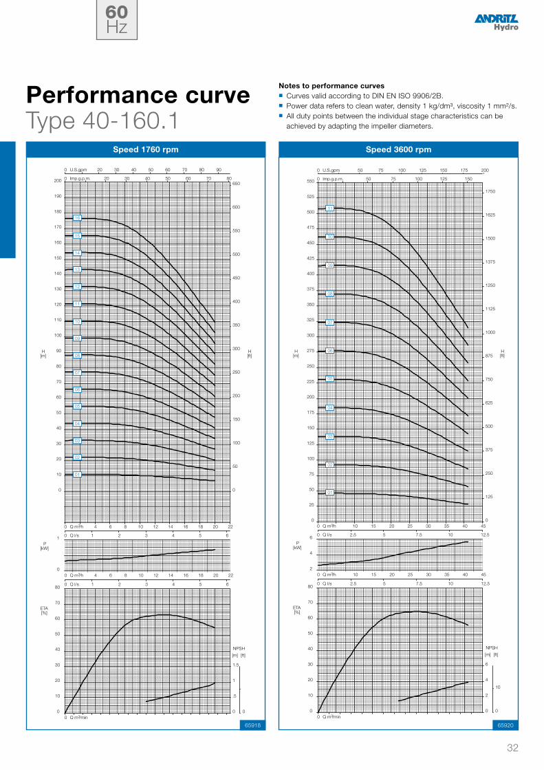
Performance curveType 100-240.3
Speed 1450 rpm Speed 2950 rpm
65973 65975
Notes to performance curves � Curves valid according to DIN EN ISO 9906/2B. � Power data refers to clean water, density 1 kg/dm³, viscosity 1 mm²/s. � All duty points between the individual stage characteristics can be achieved by adapting the impeller diameters.
50Hz

25
0
15
30
45
60
75
90
105
120
135
150
165
180
195
210
225
240
255
270
285
300
315
0
75
150
225
300
375
450
525
600
675
750
825
900
975
0 100 150 200 250 300 350 400 450 500 550 600 650
0 100 150 200 250 300 350 400 450 500 550
0 30 40 50 60 70 80 90 100 110 120 130 140 150
0 10 15 20 25 30 35 40
H[m]
H[ft]
U.S.gpm
Imp.g.p.m.
Q m /h
Q l/s
3
2
5
8
10
20
30
40
50
60
70
80
90
0
1
2
3
0
5
0 1 2
0 30 40 50 60 70 80 90 100 110 120 130 140 150
0 10 15 20 25 30 35 40
P[kW]
ETA[%]
NPSH
[m] [ft]
Q m /h
Q l/s
Q m /min
3
3
13
12
11
10
09
08
07
06
05
04
03
02
01
14
20
40
60
10
20
30
40
50
60
70
80
90
0
5
10
15
0
25
0 2 4
0 80 120 160 200 240 280 320
0 20 40 60 80
P[kW]
ETA[%]
NPSH
[m] [ft]
Q m /h
Q l/s
Q m /min
3
3
0
30
60
90
120
150
180
210
240
270
300
330
360
390
420
450
480
510
540
570
600
630
660
0
150
300
450
600
750
900
1050
1200
1350
1500
1650
1800
1950
2100
0 400 600 800 1000 1200 1400
0 200 400 600 800 1000
0 80 120 160 200 240 280 320
0 20 40 60 80
H[m]
H[ft]
U.S.gpm
Imp.g.p.m.
Q m /h
Q l/s
3
07
06
05
04
03
02
01
Performance curveType 100-240.4
Speed 1450 rpm Speed 2950 rpm
65977 65979
Notes to performance curves � Curves valid according to DIN EN ISO 9906/2B. � Power data refers to clean water, density 1 kg/dm³, viscosity 1 mm²/s. � All duty points between the individual stage characteristics can be achieved by adapting the impeller diameters.
50Hz

26
0
15
30
45
60
75
90
105
120
135
150
165
180
195
210
225
240
255
270
285
300
315
0
75
150
225
300
375
450
525
600
675
750
825
900
975
0 200 300 400 500 600 700 800
0 200 300 400 500 600 700
0 40 60 80 100 120 140 160 180 200
0 10 20 30 40 50
H[m]
H[ft]
U.S.gpm
Imp.g.p.m.
Q m /h
Q l/s
3
4
8
12
10
20
30
40
50
60
70
80
90
0
1
2
3
0
5
0 1 2 3
0 40 60 80 100 120 140 160 180 200
0 10 20 30 40 50
P[kW]
ETA[%]
NPSH
[m] [ft]
Q m /h
Q l/s
Q m /min
3
3
12
11
10
09
08
07
06
05
04
03
02
01
0
25
50
75
100
125
150
175
200
225
250
275
300
325
350
375
400
425
450
475
500
525
550
0
125
250
375
500
625
750
875
1000
1125
1250
1375
1500
1625
1750
0 500 750 1000 1250 1500 1750 2000
0 500 750 1000 1250 1500
0 100 150 200 250 300 350 400 450
0 25 50 75 100 125
H[m]
H[ft]
U.S.gpm
Imp.g.p.m.
Q m /h
Q l/s
3
30
60
90
10
20
30
40
50
60
70
80
90
0
5
10
15
0
25
0 2 3 4 5 6 7
0 100 150 200 250 300 350 400 450
0 25 50 75 100 125
P[kW]
ETA[%]
NPSH
[m] [ft]
Q m /h
Q l/s
Q m /min
3
3
05
04
03
02
01
Performance curveType 125-260.1
Speed 1450 rpm Speed 2950 rpm
65981 65983
Notes to performance curves � Curves valid according to DIN EN ISO 9906/2B. � Power data refers to clean water, density 1 kg/dm³, viscosity 1 mm²/s. � All duty points between the individual stage characteristics can be achieved by adapting the impeller diameters.
50Hz

27
0
15
30
45
60
75
90
105
120
135
150
165
180
195
210
225
240
255
270
285
300
315
0
75
150
225
300
375
450
525
600
675
750
825
900
975
0 200 300 400 500 600 700 800 900 1000 1100 1200
0 200 300 400 500 600 700 800 900 1000
0 40 60 80 100 120 140 160 180 200 220 240 260 280
0 10 20 30 40 50 60 70
H[m]
H[ft]
U.S.gpm
Imp.g.p.m.
Q m /h
Q l/s
3
5
10
15
10
20
30
40
50
60
70
80
90
0
2
4
6
0
10
0 1 2 3 4
0 40 60 80 100 120 140 160 180 200 220 240 260 280
0 10 20 30 40 50 60 70
P[kW]
ETA[%]
NPSH
[m] [ft]
Q m /h
Q l/s
Q m /min
3
3
12
11
10
09
08
07
06
05
04
03
02
01
0
25
50
75
100
125
150
175
200
225
250
275
300
325
350
375
400
425
450
475
500
525
550
0
125
250
375
500
625
750
875
1000
1125
1250
1375
1500
1625
1750
0 500 750 1000 1250 1500 1750 2000 2250 2500
0 500 750 1000 1250 1500 1750 2000
0 100 150 200 250 300 350 400 450 500 550 600
0 25 50 75 100 125 150
H[m]
H[ft]
U.S.gpm
Imp.g.p.m.
Q m /h
Q l/s
3
40
80
120
10
20
30
40
50
60
70
80
90
0
10
20
30
0
50
0 2 3 4 5 6 7 8 9 10
0 100 150 200 250 300 350 400 450 500 550 600
0 25 50 75 100 125 150
P[kW]
ETA[%]
NPSH
[m] [ft]
Q m /h
Q l/s
Q m /min
3
3
05
04
03
02
01
Performance curveType 125-260.2
Speed 1450 rpm Speed 2950 rpm
65985 65987
Notes to performance curves � Curves valid according to DIN EN ISO 9906/2B. � Power data refers to clean water, density 1 kg/dm³, viscosity 1 mm²/s. � All duty points between the individual stage characteristics can be achieved by adapting the impeller diameters.
50Hz

28
0
20
40
60
80
100
120
140
160
180
200
220
240
260
280
300
320
340
360
380
400
420
0
100
200
300
400
500
600
700
800
900
1000
1100
1200
1300
0 250 500 750 1000 1250 1500
0 250 500 750 1000 1250
0 50 100 150 200 250 300 350
0 25 50 75
H[m]
H[ft]
U.S.gpm
Imp.g.p.m.
Q m /h
Q l/s
3
5
15
25
10
20
30
40
50
60
70
80
90
0
2
4
6
0
10
0 1 2 3 4 5
0 50 100 150 200 250 300 350
0 25 50 75
P[kW]
ETA[%]
NPSH
[m] [ft]
Q m /h
Q l/s
Q m /min
3
3
12
11
10
09
08
07
06
05
04
03
02
01
25
50
75
100
125
150
175
200
225
250
275
300
325
350
375
400
425
450
475
500
525
550
575
125
250
375
500
625
750
875
1000
1125
1250
1375
1500
1625
1750
1875
0 500 750 1000 1250 1500 1750 2000 2250 2500 2750 3000
0 500 750 1000 1250 1500 1750 2000 2250 2500
0 100 150 200 250 300 350 400 450 500 550 600 650 700
0 25 50 75 100 125 150 175
H[m]
H[ft]
U.S.gpm
Imp.g.p.m.
Q m /h
Q l/s
3
0
100
200
10
20
30
40
50
60
70
80
90
0
10
20
30
0
50
0 2 3 4 5 6 7 8 9 10 11
0 100 150 200 250 300 350 400 450 500 550 600 650 700
0 25 50 75 100 125 150 175
P[kW]
ETA[%]
NPSH
[m] [ft]
Q m /h
Q l/s
Q m /min
3
3
04
03
02
01
Performance curveType 150-305.1
Speed 1450 rpm Speed 2950 rpm
65989 65991
Notes to performance curves � Curves valid according to DIN EN ISO 9906/2B. � Power data refers to clean water, density 1 kg/dm³, viscosity 1 mm²/s. � All duty points between the individual stage characteristics can be achieved by adapting the impeller diameters.
50Hz

29
0
20
40
60
80
100
120
140
160
180
200
220
240
260
280
300
320
340
360
380
400
420
440
0
100
200
300
400
500
600
700
800
900
1000
1100
1200
1300
1400
0 500 750 1000 1250 1500 1750 2000
0 500 750 1000 1250 1500
0 100 150 200 250 300 350 400 450
0 25 50 75 100 125
H[m]
H[ft]
U.S.gpm
Imp.g.p.m.
Q m /h
Q l/s
3
10
20
30
10
20
30
40
50
60
70
80
90
0
3
6
9
0
15
0 2 3 4 5 6 7
0 100 150 200 250 300 350 400 450
0 25 50 75 100 125
P[kW]
ETA[%]
NPSH
[m] [ft]
Q m /h
Q l/s
Q m /min
3
3
12
11
10
09
08
07
06
05
04
03
02
01
50
75
100
125
150
175
200
225
250
275
300
325
350
375
400
425
450
475
500
525
550
575
600
250
375
500
625
750
875
1000
1125
1250
1375
1500
1625
1750
1875
0 1000 1500 2000 2500 3000 3500 4000
0 1000 1500 2000 2500 3000
0 200 300 400 500 600 700 800 900
0 50 100 150 200 250
H[m]
H[ft]
U.S.gpm
Imp.g.p.m.
Q m /h
Q l/s
3
100
200
300
10
20
30
40
50
60
70
80
90
0
10
20
30
0
50
0 3 4 5 6 7 8 9 10 11 12 13 14
0 200 300 400 500 600 700 800 900
0 50 100 150 200 250
P[kW]
ETA[%]
NPSH
[m] [ft]
Q m /h
Q l/s
Q m /min
3
3
04
03
02
01
Performance curveType 150-305.2
Speed 1450 rpm Speed 2950 rpm
65993 65995
Notes to performance curves � Curves valid according to DIN EN ISO 9906/2B. � Power data refers to clean water, density 1 kg/dm³, viscosity 1 mm²/s. � All duty points between the individual stage characteristics can be achieved by adapting the impeller diameters.
50Hz

30
0
15
30
45
60
75
90
105
120
135
150
165
180
195
210
225
240
255
270
285
300
0
75
150
225
300
375
450
525
600
675
750
825
900
975
0 250 500 750 1000 1250 1500
0 250 500 750 1000 1250
0 50 100 150 200 250 300 350
0 25 50 75
H[m]
H[ft]
U.S.gpm
Imp.g.p.m.
Q m /h
Q l/s
3
5
10
15
10
20
30
40
50
60
70
80
90
0
1
2
3
0
5
0 1 2 3 4 5
0 50 100 150 200 250 300 350
0 25 50 75
P[kW]
ETA[%]
NPSH
[m] [ft]
Q m /h
Q l/s
Q m /min
3
3
12
11
10
09
08
07
06
05
04
03
02
01
0
25
50
75
100
125
150
175
200
225
250
275
300
325
350
375
400
425
450
475
500
525
550
0
125
250
375
500
625
750
875
1000
1125
1250
1375
1500
1625
1750
0 500 750 1000 1250 1500 1750 2000 2250
0 500 750 1000 1250 1500 1750 2000
0 100 150 200 250 300 350 400 450 500 550
0 25 50 75 100 125 150
H[m]
H[ft]
U.S.gpm
Imp.g.p.m.
Q m /h
Q l/s
3
20
40
60
10
20
30
40
50
60
70
80
90
0
3
6
9
0
15
0 2 3 4 5 6 7 8 9
0 100 150 200 250 300 350 400 450 500 550
0 25 50 75 100 125 150
P[kW]
ETA[%]
NPSH
[m] [ft]
Q m /h
Q l/s
Q m /min
3
3
11
10
09
08
07
06
05
04
03
02
01
Performance curveType 200-360.1
Speed 980 rpm Speed 1450 rpm
65997 65999
Notes to performance curves � Curves valid according to DIN EN ISO 9906/2B. � Power data refers to clean water, density 1 kg/dm³, viscosity 1 mm²/s. � All duty points between the individual stage characteristics can be achieved by adapting the impeller diameters.
50Hz

31
0
15
30
45
60
75
90
105
120
135
150
165
180
195
210
225
240
255
270
285
300
0
75
150
225
300
375
450
525
600
675
750
825
900
975
0 500 750 1000 1250 1500 1750 2000
0 500 750 1000 1250 1500 1750
0 100 150 200 250 300 350 400 450 500
0 25 50 75 100 125
H[m]
H[ft]
U.S.gpm
Imp.g.p.m.
Q m /h
Q l/s
3
5
15
25
10
20
30
40
50
60
70
80
90
0
2
4
6
0
10
0 2 3 4 5 6 7 8
0 100 150 200 250 300 350 400 450 500
0 25 50 75 100 125
P[kW]
ETA[%]
NPSH
[m] [ft]
Q m /h
Q l/s
Q m /min
3
3
12
11
10
09
08
07
06
05
04
03
02
01
0
25
50
75
100
125
150
175
200
225
250
275
300
325
350
375
400
425
450
475
500
525
550
0
125
250
375
500
625
750
875
1000
1125
1250
1375
1500
1625
1750
0 500 750 1000 1250 1500 1750 2000 2250 2500 2750 3000 3250
0 500 750 1000 1250 1500 1750 2000 2250 2500 2750
0 150 200 250 300 350 400 450 500 550 600 650 700 750
0 50 75 100 125 150 175 200
H[m]
H[ft]
U.S.gpm
Imp.g.p.m.
Q m /h
Q l/s
3
20
40
60
10
20
30
40
50
60
70
80
90
0
3
6
9
0
15
0 2 3 4 5 6 7 8 9 10 11 12
0 150 200 250 300 350 400 450 500 550 600 650 700 750
0 50 75 100 125 150 175 200
P[kW]
ETA[%]
NPSH
[m] [ft]
Q m /h
Q l/s
Q m /min
3
3
11
10
09
08
07
06
05
04
03
02
01
Performance curveType 200-360.2
Speed 980 rpm Speed 1450 rpm
66001 66003
Notes to performance curves � Curves valid according to DIN EN ISO 9906/2B. � Power data refers to clean water, density 1 kg/dm³, viscosity 1 mm²/s. � All duty points between the individual stage characteristics can be achieved by adapting the impeller diameters.
50Hz
32
0
1
0
10
20
30
40
50
60
70
80
0
.5
1
1.5
0
0
0 4 6 8 10 12 14 16 18 20 22
0 1 2 3 4 5 6
P[kW]
ETA[%]
NPSH
[m] [ft]
Q m /h
Q l/s
Q m /min
3
3
0
10
20
30
40
50
60
70
80
90
100
110
120
130
140
150
160
170
180
190
200
0
50
100
150
200
250
300
350
400
450
500
550
600
650
0 20 30 40 50 60 70 80 90
0 20 30 40 50 60 70 80
0 4 6 8 10 12 14 16 18 20 22
0 1 2 3 4 5 6
H[m]
H[ft]
U.S.gpm
Imp.g.p.m.
Q m /h
Q l/s
3
13
12
11
10
09
08
07
06
05
04
03
02
01
14
15
16
2
4
6
0
10
20
30
40
50
60
70
80
0
2
4
6
0
10
0
0 10 15 20 25 30 35 40 45
0 2.5 5 7.5 10 12.5
P[kW]
ETA[%]
NPSH
[m] [ft]
Q m /h
Q l/s
Q m /min
3
3
0
25
50
75
100
125
150
175
200
225
250
275
300
325
350
375
400
425
450
475
500
525
550
0
125
250
375
500
625
750
875
1000
1125
1250
1375
1500
1625
1750
0 50 75 100 125 150 175 200
0 50 75 100 125 150
0 10 15 20 25 30 35 40 45
0 2.5 5 7.5 10 12.5
H[m]
H[ft]
U.S.gpm
Imp.g.p.m.
Q m /h
Q l/s
3
11
10
09
08
07
06
05
04
03
02
01
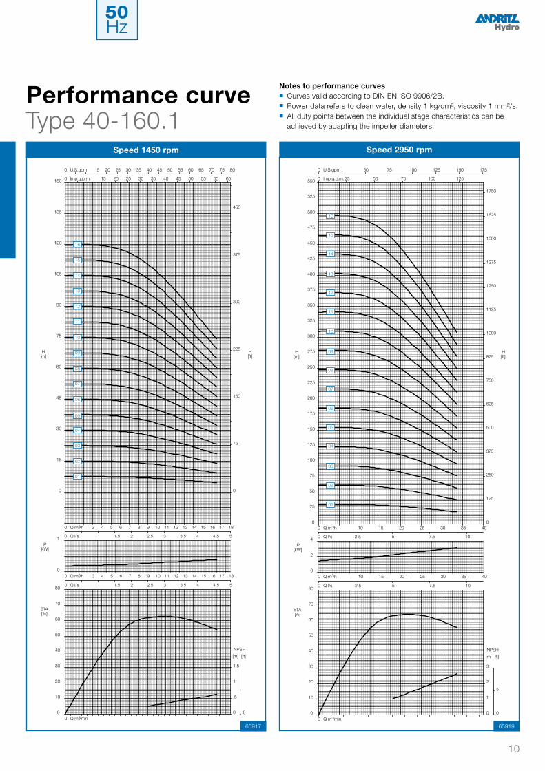
Performance curveType 40-160.1
Speed 1760 rpm Speed 3600 rpm
65918 65920
Notes to performance curves � Curves valid according to DIN EN ISO 9906/2B. � Power data refers to clean water, density 1 kg/dm³, viscosity 1 mm²/s. � All duty points between the individual stage characteristics can be achieved by adapting the impeller diameters.
60Hz

33
0
10
20
30
40
50
60
70
80
90
100
110
120
130
140
150
160
170
180
190
200
0
50
100
150
200
250
300
350
400
450
500
550
600
650
0 25 50 75 100 125
0 25 50 75 100
0 5 10 15 20 25 30
0 2.5 5 7.5
H[m]
H[ft]
U.S.gpm
Imp.g.p.m.
Q m /h
Q l/s
3
0
1
0
10
20
30
40
50
60
70
80
0
.5
1
1.5
0
0
0 5 10 15 20 25 30
0 2.5 5 7.5
P[kW]
ETA[%]
NPSH
[m] [ft]
Q m /h
Q l/s
Q m /min
3
3
13
12
11
10
09
08
07
06
05
04
03
02
01
14
15
16
0
4
8
0
10
20
30
40
50
60
70
80
0
2
4
6
0
10
0 1
0 10 15 20 25 30 35 40 45 50 55 60
0 2.5 5 7.5 10 12.5 15
P[kW]
ETA[%]
NPSH
[m] [ft]
Q m /h
Q l/s
Q m /min
3
3
0
25
50
75
100
125
150
175
200
225
250
275
300
325
350
375
400
425
450
475
500
525
550
0
125
250
375
500
625
750
875
1000
1125
1250
1375
1500
1625
1750
0 50 75 100 125 150 175 200 225 250
0 50 75 100 125 150 175 200
0 10 15 20 25 30 35 40 45 50 55 60
0 2.5 5 7.5 10 12.5 15
H[m]
H[ft]
U.S.gpm
Imp.g.p.m.
Q m /h
Q l/s
3
11
10
09
08
07
06
05
04
03
02
01
Performance curveType 40-160.2
Speed 1760 rpm Speed 3600 rpm
65922 65924
Notes to performance curves � Curves valid according to DIN EN ISO 9906/2B. � Power data refers to clean water, density 1 kg/dm³, viscosity 1 mm²/s. � All duty points between the individual stage characteristics can be achieved by adapting the impeller diameters.
60Hz

34
0
10
20
30
40
50
60
70
80
90
100
110
120
130
140
150
160
170
180
190
200
210
220
0
50
100
150
200
250
300
350
400
450
500
550
600
650
700
0 20 30 40 50 60 70 80 90
0 20 30 40 50 60 70 80
0 4 6 8 10 12 14 16 18 20 22
0 1 2 3 4 5 6
H[m]
H[ft]
U.S.gpm
Imp.g.p.m.
Q m /h
Q l/s
3
0
1
0
10
20
30
40
50
60
70
80
0
.5
1
1.5
0
0
0 4 6 8 10 12 14 16 18 20 22
0 1 2 3 4 5 6
P[kW]
ETA[%]
NPSH
[m] [ft]
Q m /h
Q l/s
Q m /min
3
3
13
12
11
10
09
08
07
06
05
04
03
02
01
14
15
16
0
4
8
0
10
20
30
40
50
60
70
80
0
2
4
6
0
10
0
0 10 15 20 25 30 35 40 45
0 2.5 5 7.5 10 12.5
P[kW]
ETA[%]
NPSH
[m] [ft]
Q m /h
Q l/s
Q m /min
3
3
0
30
60
90
120
150
180
210
240
270
300
330
360
390
420
450
480
510
540
570
600
630
660
0
150
300
450
600
750
900
1050
1200
1350
1500
1650
1800
1950
2100
0 50 75 100 125 150 175 200
0 50 75 100 125 150
0 10 15 20 25 30 35 40 45
0 2.5 5 7.5 10 12.5
U.S.gpm
Imp.g.p.m.
Q m /h
Q l/s
3
H[m]
H[ft]
11
10
09
08
07
06
05
04
03
02
01
Performance curveType 40-160.3
Speed 1760 rpm Speed 3600 rpm
65926 65928
Notes to performance curves � Curves valid according to DIN EN ISO 9906/2B. � Power data refers to clean water, density 1 kg/dm³, viscosity 1 mm²/s. � All duty points between the individual stage characteristics can be achieved by adapting the impeller diameters.
60Hz

35
0
10
20
30
40
50
60
70
80
90
100
110
120
130
140
150
160
170
180
190
200
210
220
0
50
100
150
200
250
300
350
400
450
500
550
600
650
700
0 25 50 75 100 125
0 25 50 75 100
0 5 10 15 20 25 30
0 2.5 5 7.5
H[m]
H[ft]
U.S.gpm
Imp.g.p.m.
Q m /h
Q l/s
3
0
1
2
0
10
20
30
40
50
60
70
80
0
.5
1
1.5
0
0
0 5 10 15 20 25 30
0 2.5 5 7.5
P[kW]
ETA[%]
NPSH
[m] [ft]
Q m /h
Q l/s
Q m /min
3
3
13
12
11
10
09
08
07
06
05
04
03
02
01
14
15
16
2
6
10
0
10
20
30
40
50
60
70
80
0
2
4
6
0
10
0 1
0 10 15 20 25 30 35 40 45 50 55 60
0 2.5 5 7.5 10 12.5 15
P[kW]
ETA[%]
NPSH
[m] [ft]
Q m /h
Q l/s
Q m /min
3
3
0
30
60
90
120
150
180
210
240
270
300
330
360
390
420
450
480
510
540
570
600
630
660
0
150
300
450
600
750
900
1050
1200
1350
1500
1650
1800
1950
2100
0 50 75 100 125 150 175 200 225 250
0 50 75 100 125 150 175 200
0 10 15 20 25 30 35 40 45 50 55 60
0 2.5 5 7.5 10 12.5 15
H[m]
H[ft]
U.S.gpm
Imp.g.p.m.
Q m /h
Q l/s
3
11
10
09
08
07
06
05
04
03
02
01
Performance curveType 40-160.4
Speed 1760 rpm Speed 3600 rpm
65930 65932
Notes to performance curves � Curves valid according to DIN EN ISO 9906/2B. � Power data refers to clean water, density 1 kg/dm³, viscosity 1 mm²/s. � All duty points between the individual stage characteristics can be achieved by adapting the impeller diameters.
60Hz

36
0
10
20
30
40
50
60
70
80
90
100
110
120
130
140
150
160
170
180
190
200
210
220
0
50
100
150
200
250
300
350
400
450
500
550
600
650
700
0 50 75 100 125 150 175
0 25 50 75 100 125
0 10 15 20 25 30 35 40
0 2.5 5 7.5 10
H[m]
H[ft]
U.S.gpm
Imp.g.p.m.
Q m /h
Q l/s
3
0
1
2
0
10
20
30
40
50
60
70
80
0
.5
1
1.5
0
0
0 10 15 20 25 30 35 40
0 2.5 5 7.5 10
P[kW]
ETA[%]
NPSH
[m] [ft]
Q m /h
Q l/s
Q m /min
3
3
13
12
11
10
09
08
07
06
05
04
03
02
01
14
15
16
4
8
12
0
10
20
30
40
50
60
70
80
0
2
4
6
0
10
0 1
0 20 30 40 50 60 70 80
0 5 10 15 20
P[kW]
ETA[%]
NPSH
[m] [ft]
Q m /h
Q l/s
Q m /min
3
3
0
20
40
60
80
100
120
140
160
180
200
220
240
260
280
300
320
340
360
380
400
420
440
0
100
200
300
400
500
600
700
800
900
1000
1100
1200
1300
1400
0 100 150 200 250 300 350
0 50 100 150 200 250
0 20 30 40 50 60 70 80
0 5 10 15 20
H[m]
H[ft]
U.S.gpm
Imp.g.p.m.
Q m /h
Q l/s
3
07
06
05
04
03
02
01
Performance curveType 50-195.1
Speed 1760 rpm Speed 3600 rpm
65934 65936
Notes to performance curves � Curves valid according to DIN EN ISO 9906/2B. � Power data refers to clean water, density 1 kg/dm³, viscosity 1 mm²/s. � All duty points between the individual stage characteristics can be achieved by adapting the impeller diameters.
60Hz

37
0
10
20
30
40
50
60
70
80
90
100
110
120
130
140
150
160
170
180
190
200
210
220
0
50
100
150
200
250
300
350
400
450
500
550
600
650
700
0 50 75 100 125 150 175 200 225
0 50 75 100 125 150 175 200
0 10 15 20 25 30 35 40 45 50 55
0 2.5 5 7.5 10 12.5 15
H[m]
H[ft]
U.S.gpm
Imp.g.p.m.
Q m /h
Q l/s
3
0
1
2
0
10
20
30
40
50
60
70
80
0
1
2
3
0
5
0
0 10 15 20 25 30 35 40 45 50 55
0 2.5 5 7.5 10 12.5 15
P[kW]
ETA[%]
NPSH
[m] [ft]
Q m /h
Q l/s
Q m /min
3
3
13
12
11
10
09
08
07
06
05
04
03
02
01
14
15
16
5
10
15
0
10
20
30
40
50
60
70
80
0
3
6
9
0
15
0 1
0 20 30 40 50 60 70 80 90 100 110
0 5 10 15 20 25 30
P[kW]
ETA[%]
NPSH
[m] [ft]
Q m /h
Q l/s
Q m /min
3
3
0
20
40
60
80
100
120
140
160
180
200
220
240
260
280
300
320
340
360
380
400
420
440
0
100
200
300
400
500
600
700
800
900
1000
1100
1200
1300
1400
0 100 150 200 250 300 350 400 450
0 100 150 200 250 300 350 400
0 20 30 40 50 60 70 80 90 100 110
0 5 10 15 20 25 30
H[m]
H[ft]
U.S.gpm
Imp.g.p.m.
Q m /h
Q l/s
3
07
06
05
04
03
02
01
Performance curveType 50-195.2
Speed 1760 rpm Speed 3600 rpm
65938 65940
Notes to performance curves � Curves valid according to DIN EN ISO 9906/2B. � Power data refers to clean water, density 1 kg/dm³, viscosity 1 mm²/s. � All duty points between the individual stage characteristics can be achieved by adapting the impeller diameters.
60Hz

38
0
15
30
45
60
75
90
105
120
135
150
165
180
195
210
225
240
255
270
285
300
315
330
0
75
150
225
300
375
450
525
600
675
750
825
900
975
1050
0 50 75 100 125 150 175
0 25 50 75 100 125
0 10 15 20 25 30 35 40
0 2.5 5 7.5 10
H[m]
H[ft]
U.S.gpm
Imp.g.p.m.
Q m /h
Q l/s
3
0
2
4
0
10
20
30
40
50
60
70
80
0
1
2
3
0
5
0
0 10 15 20 25 30 35 40
0 2.5 5 7.5 10
P[kW]
ETA[%]
NPSH
[m] [ft]
Q m /h
Q l/s
Q m /min
3
3
13
12
11
10
09
08
07
06
05
04
03
02
01
14
15
16
5
15
25
0
10
20
30
40
50
60
70
80
0
3
6
9
0
15
0 1
0 20 30 40 50 60 70 80 90
0 5 10 15 20 25
P[kW]
ETA[%]
NPSH
[m] [ft]
Q m /h
Q l/s
Q m /min
3
3
0
30
60
90
120
150
180
210
240
270
300
330
360
390
420
450
480
510
540
570
600
630
660
0
150
300
450
600
750
900
1050
1200
1350
1500
1650
1800
1950
2100
0 100 150 200 250 300 350 400
0 100 150 200 250 300
0 20 30 40 50 60 70 80 90
0 5 10 15 20 25
H[m]
H[ft]
U.S.gpm
Imp.g.p.m.
Q m /h
Q l/s
3
07
06
05
04
03
02
01
Performance curveType 50-195.3
Speed 1760 rpm Speed 3600 rpm
65942 65944
Notes to performance curves � Curves valid according to DIN EN ISO 9906/2B. � Power data refers to clean water, density 1 kg/dm³, viscosity 1 mm²/s. � All duty points between the individual stage characteristics can be achieved by adapting the impeller diameters.
60Hz

39
10
25
40
55
70
85
100
115
130
145
160
175
190
205
220
235
250
265
280
295
310
325
340
75
150
225
300
375
450
525
600
675
750
825
900
975
1050
0 50 75 100 125 150 175 200 225
0 50 75 100 125 150 175 200
0 10 15 20 25 30 35 40 45 50 55
0 2.5 5 7.5 10 12.5 15
H[m]
H[ft]
U.S.gpm
Imp.g.p.m.
Q m /h
Q l/s
3
0
2
4
0
10
20
30
40
50
60
70
80
0
1
2
3
0
5
0
0 10 15 20 25 30 35 40 45 50 55
0 2.5 5 7.5 10 12.5 15
P[kW]
ETA[%]
NPSH
[m] [ft]
Q m /h
Q l/s
Q m /min
3
3
13
12
11
10
09
08
07
06
05
04
03
02
01
14
15
16
5
15
25
0
10
20
30
40
50
60
70
80
0
3
6
9
0
15
0 1
0 20 30 40 50 60 70 80 90 100 110
0 5 10 15 20 25 30
P[kW]
ETA[%]
NPSH
[m] [ft]
Q m /h
Q l/s
Q m /min
3
3
0
30
60
90
120
150
180
210
240
270
300
330
360
390
420
450
480
510
540
570
600
630
660
0
150
300
450
600
750
900
1050
1200
1350
1500
1650
1800
1950
2100
0 100 150 200 250 300 350 400 450
0 100 150 200 250 300 350 400
0 20 30 40 50 60 70 80 90 100 110
0 5 10 15 20 25 30
H[m]
H[ft]
U.S.gpm
Imp.g.p.m.
Q m /h
Q l/s
3
07
06
05
04
03
02
01
Performance curveType 50-195.4
Speed 1760 rpm Speed 3600 rpm
65946 65948
Notes to performance curves � Curves valid according to DIN EN ISO 9906/2B. � Power data refers to clean water, density 1 kg/dm³, viscosity 1 mm²/s. � All duty points between the individual stage characteristics can be achieved by adapting the impeller diameters.
60Hz

40
0
10
20
30
40
50
60
70
80
90
100
110
120
130
140
150
160
170
180
190
200
210
220
0
50
100
150
200
250
300
350
400
450
500
550
600
650
700
0 50 75 100 125 150 175 200 225 250 275 300
0 50 75 100 125 150 175 200 225 250
0 10 15 20 25 30 35 40 45 50 55 60 65 70
0 2.5 5 7.5 10 12.5 15 17.5
H[m]
H[ft]
U.S.gpm
Imp.g.p.m.
Q m /h
Q l/s
3
0
2
4
0
10
20
30
40
50
60
70
80
0
1
2
3
0
5
0 1
0 10 15 20 25 30 35 40 45 50 55 60 65 70
0 2.5 5 7.5 10 12.5 15 17.5
P[kW]
ETA[%]
NPSH
[m] [ft]
Q m /h
Q l/s
Q m /min
3
3
13
12
11
10
09
08
07
06
05
04
03
02
01
14
5
15
25
0
10
20
30
40
50
60
70
80
0
4
8
12
0
20
0 1 2
0 30 40 50 60 70 80 90 100 110 120 130 140 150
0 10 15 20 25 30 35 40
P[kW]
ETA[%]
NPSH
[m] [ft]
Q m /h
Q l/s
Q m /min
3
3
15
30
45
60
75
90
105
120
135
150
165
180
195
210
225
240
255
270
285
300
315
330
345
75
150
225
300
375
450
525
600
675
750
825
900
975
1050
1125
0 100 150 200 250 300 350 400 450 500 550 600 650
0 100 150 200 250 300 350 400 450 500 550
0 30 40 50 60 70 80 90 100 110 120 130 140 150
0 10 15 20 25 30 35 40
H[m]
H[ft]
U.S.gpm
Imp.g.p.m.
Q m /h
Q l/s
3
05
04
03
02
01
Performance curveType 80-220.1
Speed 1760 rpm Speed 3600 rpm
65950 65952
Notes to performance curves � Curves valid according to DIN EN ISO 9906/2B. � Power data refers to clean water, density 1 kg/dm³, viscosity 1 mm²/s. � All duty points between the individual stage characteristics can be achieved by adapting the impeller diameters.
60Hz

41
7
17
27
37
47
57
67
77
87
97
107
117
127
137
147
157
167
177
187
197
207
217
227
50
100
150
200
250
300
350
400
450
500
550
600
650
700
0 100 150 200 250 300 350 400
0 100 150 200 250 300 350
0 20 30 40 50 60 70 80 90 100
0 5 10 15 20 25
H[m]
H[ft]
U.S.gpm
Imp.g.p.m.
Q m /h
Q l/s
3
0
2
4
10
20
30
40
50
60
70
80
90
0
1
2
3
0
5
0 1
0 20 30 40 50 60 70 80 90 100
0 5 10 15 20 25
P[kW]
ETA[%]
NPSH
[m] [ft]
Q m /h
Q l/s
Q m /min
3
3
13
12
11
10
09
08
07
06
05
04
03
02
01
14
10
20
30
10
20
30
40
50
60
70
80
90
0
5
10
15
0
25
0 1 2 3
0 50 75 100 125 150 175 200
0 12.5 25 37.5 50
P[kW]
ETA[%]
NPSH
[m] [ft]
Q m /h
Q l/s
Q m /min
3
3
15
30
45
60
75
90
105
120
135
150
165
180
195
210
225
240
255
270
285
300
315
330
345
75
150
225
300
375
450
525
600
675
750
825
900
975
1050
1125
0 250 375 500 625 750 875
0 125 250 375 500 625
0 50 75 100 125 150 175 200
0 12.5 25 37.5 50
H[m]
H[ft]
U.S.gpm
Imp.g.p.m.
Q m /h
Q l/s
3
05
04
03
02
01
Performance curveType 80-220.2
Speed 1760 rpm Speed 3600 rpm
65954 65956
Notes to performance curves � Curves valid according to DIN EN ISO 9906/2B. � Power data refers to clean water, density 1 kg/dm³, viscosity 1 mm²/s. � All duty points between the individual stage characteristics can be achieved by adapting the impeller diameters.
60Hz

42
0
20
40
60
80
100
120
140
160
180
200
220
240
260
280
300
320
340
360
380
400
420
440
0
100
200
300
400
500
600
700
800
900
1000
1100
1200
1300
1400
0 100 150 200 250 300 350
0 50 100 150 200 250
0 20 30 40 50 60 70 80
0 5 10 15 20
H[m]
H[ft]
U.S.gpm
Imp.g.p.m.
Q m /h
Q l/s
3
0
3
6
0
10
20
30
40
50
60
70
80
0
1
2
3
0
5
0 1
0 20 30 40 50 60 70 80
0 5 10 15 20
P[kW]
ETA[%]
NPSH
[m] [ft]
Q m /h
Q l/s
Q m /min
3
3
13
12
11
10
09
08
07
06
05
04
03
02
01
14
10
30
50
0
10
20
30
40
50
60
70
80
0
3
6
9
0
15
0 1 2
0 25 50 75 100 125 150
0 12.5 25 37.5
P[kW]
ETA[%]
NPSH
[m] [ft]
Q m /h
Q l/s
Q m /min
3
3
0
25
50
75
100
125
150
175
200
225
250
275
300
325
350
375
400
425
450
475
500
525
550
0
125
250
375
500
625
750
875
1000
1125
1250
1375
1500
1625
1750
0 125 250 375 500 625
0 125 250 375 500
0 25 50 75 100 125 150
0 12.5 25 37.5
H[m]
H[ft]
U.S.gpm
Imp.g.p.m.
Q m /h
Q l/s
3
05
04
03
02
01
Performance curveType 80-220.3
Speed 1760 rpm Speed 3600 rpm
65958 65960
Notes to performance curves � Curves valid according to DIN EN ISO 9906/2B. � Power data refers to clean water, density 1 kg/dm³, viscosity 1 mm²/s. � All duty points between the individual stage characteristics can be achieved by adapting the impeller diameters.
60Hz

43
0
20
40
60
80
100
120
140
160
180
200
220
240
260
280
300
320
340
360
380
400
420
0
100
200
300
400
500
600
700
800
900
1000
1100
1200
1300
0 100 150 200 250 300 350 400
0 100 150 200 250 300 350
0 20 30 40 50 60 70 80 90 100
0 5 10 15 20 25
H[m]
H[ft]
U.S.gpm
Imp.g.p.m.
Q m /h
Q l/s
3
0
3
6
0
10
20
30
40
50
60
70
80
0
1
2
3
0
5
0 1
0 20 30 40 50 60 70 80 90 100
0 5 10 15 20 25
P[kW]
ETA[%]
NPSH
[m] [ft]
Q m /h
Q l/s
Q m /min
3
3
13
12
11
10
09
08
07
06
05
04
03
02
01
14
15
35
55
10
20
30
40
50
60
70
80
90
0
5
10
15
0
25
0 1 2 3
0 40 60 80 100 120 140 160 180 200 220
0 10 20 30 40 50 60
P[kW]
ETA[%]
NPSH
[m] [ft]
Q m /h
Q l/s
Q m /min
3
3
0
25
50
75
100
125
150
175
200
225
250
275
300
325
350
375
400
425
450
475
500
525
550
0
125
250
375
500
625
750
875
1000
1125
1250
1375
1500
1625
1750
0 200 300 400 500 600 700 800 900
0 200 300 400 500 600 700 800
0 40 60 80 100 120 140 160 180 200 220
0 10 20 30 40 50 60
H[m]
H[ft]
U.S.gpm
Imp.g.p.m.
Q m /h
Q l/s
3
05
04
03
02
01
Performance curveType 80-220.4
Speed 1760 rpm Speed 3600 rpm
65962 65964
Notes to performance curves � Curves valid according to DIN EN ISO 9906/2B. � Power data refers to clean water, density 1 kg/dm³, viscosity 1 mm²/s. � All duty points between the individual stage characteristics can be achieved by adapting the impeller diameters.
60Hz

44
0
15
30
45
60
75
90
105
120
135
150
165
180
195
210
225
240
255
270
285
300
315
330
0
75
150
225
300
375
450
525
600
675
750
825
900
975
1050
0 100 200 300 400 500 600
0 100 200 300 400 500
0 20 40 60 80 100 120 140
0 10 20 30
H[m]
H[ft]
U.S.gpm
Imp.g.p.m.
Q m /h
Q l/s
3
0
4
8
10
20
30
40
50
60
70
80
90
0
1
2
3
0
5
0 1 2
0 20 40 60 80 100 120 140
0 10 20 30
P[kW]
ETA[%]
NPSH
[m] [ft]
Q m /h
Q l/s
Q m /min
3
3
13
12
11
10
09
08
07
06
05
04
03
02
01
14
20
40
60
10
20
30
40
50
60
70
80
90
0
5
10
15
0
25
0 1 2 3 4
0 40 60 80 100 120 140 160 180 200 220 240 260 280
0 10 20 30 40 50 60 70
P[kW]
ETA[%]
NPSH
[m] [ft]
Q m /h
Q l/s
Q m /min
3
3
0
25
50
75
100
125
150
175
200
225
250
275
300
325
350
375
400
425
450
475
500
525
550
0
125
250
375
500
625
750
875
1000
1125
1250
1375
1500
1625
1750
0 200 300 400 500 600 700 800 900 1000 1100 1200
0 200 300 400 500 600 700 800 900 1000
0 40 60 80 100 120 140 160 180 200 220 240 260 280
0 10 20 30 40 50 60 70
H[m]
H[ft]
U.S.gpm
Imp.g.p.m.
Q m /h
Q l/s
3
05
04
03
02
01
Performance curveType 100-240.1
Speed 1760 rpm Speed 3600 rpm
65966 65968
Notes to performance curves � Curves valid according to DIN EN ISO 9906/2B. � Power data refers to clean water, density 1 kg/dm³, viscosity 1 mm²/s. � All duty points between the individual stage characteristics can be achieved by adapting the impeller diameters.
60Hz

45
0
20
40
60
80
100
120
140
160
180
200
220
240
260
280
300
320
340
360
380
400
420
0
100
200
300
400
500
600
700
800
900
1000
1100
1200
1300
0 200 300 400 500 600 700 800
0 200 300 400 500 600
0 40 60 80 100 120 140 160 180
0 10 20 30 40 50
H[m]
H[ft]
U.S.gpm
Imp.g.p.m.
Q m /h
Q l/s
3
4
7
10
10
20
30
40
50
60
70
80
90
0
1
2
3
0
5
0 1 2
0 40 60 80 100 120 140 160 180
0 10 20 30 40 50
P[kW]
ETA[%]
NPSH
[m] [ft]
Q m /h
Q l/s
Q m /min
3
3
13
12
11
10
09
08
07
06
05
04
03
02
01
14
30
50
70
10
20
30
40
50
60
70
80
90
0
6
12
18
0
30
0 2 3 4 5 6
0 100 150 200 250 300 350 400
0 25 50 75 100
P[kW]
ETA[%]
NPSH
[m] [ft]
Q m /h
Q l/s
Q m /min
3
3
0
25
50
75
100
125
150
175
200
225
250
275
300
325
350
375
400
425
450
475
500
525
550
0
125
250
375
500
625
750
875
1000
1125
1250
1375
1500
1625
1750
0 500 750 1000 1250 1500 1750
0 250 500 750 1000 1250
0 100 150 200 250 300 350 400
0 25 50 75 100
H[m]
H[ft]
U.S.gpm
Imp.g.p.m.
Q m /h
Q l/s
3
05
04
03
02
01
Performance curveType 100-240.2
Speed 1760 rpm Speed 3600 rpm
65970 65972
Notes to performance curves � Curves valid according to DIN EN ISO 9906/2B. � Power data refers to clean water, density 1 kg/dm³, viscosity 1 mm²/s. � All duty points between the individual stage characteristics can be achieved by adapting the impeller diameters.
60Hz
46
0
20
40
60
80
100
120
140
160
180
200
220
240
260
280
300
320
340
360
380
400
420
440
0
100
200
300
400
500
600
700
800
900
1000
1100
1200
1300
1400
0 100 200 300 400 500 600
0 100 200 300 400 500
0 20 40 60 80 100 120 140
0 10 20 30
H[m]
H[ft]
U.S.gpm
Imp.g.p.m.
Q m /h
Q l/s
3
0
5
10
10
20
30
40
50
60
70
80
90
0
1
2
3
0
5
0 1 2
0 20 40 60 80 100 120 140
0 10 20 30
P[kW]
ETA[%]
NPSH
[m] [ft]
Q m /h
Q l/s
Q m /min
3
3
13
12
11
10
09
08
07
06
05
04
03
02
01
14
0
40
80
10
20
30
40
50
60
70
80
90
0
5
10
15
0
25
0 1 2 3 4
0 40 60 80 100 120 140 160 180 200 220 240 260 280
0 10 20 30 40 50 60 70
P[kW]
ETA[%]
NPSH
[m] [ft]
Q m /h
Q l/s
Q m /min
3
3
0
30
60
90
120
150
180
210
240
270
300
330
360
390
420
450
480
510
540
570
600
630
660
0
150
300
450
600
750
900
1050
1200
1350
1500
1650
1800
1950
2100
0 200 300 400 500 600 700 800 900 1000 1100 1200
0 200 300 400 500 600 700 800 900 1000
0 40 60 80 100 120 140 160 180 200 220 240 260 280
0 10 20 30 40 50 60 70
H[m]
H[ft]
U.S.gpm
Imp.g.p.m.
Q m /h
Q l/s
3
05
04
03
02
01
Performance curveType 100-240.3
Speed 1760 rpm Speed 3600 rpm
65974 65976
Notes to performance curves � Curves valid according to DIN EN ISO 9906/2B. � Power data refers to clean water, density 1 kg/dm³, viscosity 1 mm²/s. � All duty points between the individual stage characteristics can be achieved by adapting the impeller diameters.
60Hz

47
0
20
40
60
80
100
120
140
160
180
200
220
240
260
280
300
320
340
360
380
400
420
440
0
100
200
300
400
500
600
700
800
900
1000
1100
1200
1300
1400
0 200 300 400 500 600 700 800
0 200 300 400 500 600
0 40 60 80 100 120 140 160 180
0 10 20 30 40 50
H[m]
H[ft]
U.S.gpm
Imp.g.p.m.
Q m /h
Q l/s
3
4
8
12
10
20
30
40
50
60
70
80
90
0
2
4
6
0
10
0 1 2
0 40 60 80 100 120 140 160 180
0 10 20 30 40 50
P[kW]
ETA[%]
NPSH
[m] [ft]
Q m /h
Q l/s
Q m /min
3
3
13
12
11
10
09
08
07
06
05
04
03
02
01
14
30
70
110
10
20
30
40
50
60
70
80
90
0
10
20
30
0
50
0 2 3 4 5 6
0 100 150 200 250 300 350 400
0 25 50 75 100
P[kW]
ETA[%]
NPSH
[m] [ft]
Q m /h
Q l/s
Q m /min
3
3
0
30
60
90
120
150
180
210
240
270
300
330
360
390
420
450
480
510
540
570
600
630
660
0
150
300
450
600
750
900
1050
1200
1350
1500
1650
1800
1950
2100
0 500 750 1000 1250 1500 1750
0 250 500 750 1000 1250
0 100 150 200 250 300 350 400
0 25 50 75 100
H[m]
H[ft]
U.S.gpm
Imp.g.p.m.
Q m /h
Q l/s
3
05
04
03
02
01
Performance curveType 100-240.4
Speed 1760 rpm Speed 3600 rpm
65978 65980
Notes to performance curves � Curves valid according to DIN EN ISO 9906/2B. � Power data refers to clean water, density 1 kg/dm³, viscosity 1 mm²/s. � All duty points between the individual stage characteristics can be achieved by adapting the impeller diameters.
60Hz

48
0
20
40
60
80
100
120
140
160
180
200
220
240
260
280
300
320
340
360
380
400
420
440
0
100
200
300
400
500
600
700
800
900
1000
1100
1200
1300
1400
0 250 375 500 625 750 875 1000
0 250 375 500 625 750 875
0 50 75 100 125 150 175 200 225 250
0 12.5 25 37.5 50 62.5
H[m]
H[ft]
U.S.gpm
Imp.g.p.m.
Q m /h
Q l/s
3
0
10
20
10
20
30
40
50
60
70
80
90
0
2
4
6
0
10
0 1 2 3 4
0 50 75 100 125 150 175 200 225 250
0 12.5 25 37.5 50 62.5
P[kW]
ETA[%]
NPSH
[m] [ft]
Q m /h
Q l/s
Q m /min
3
3
12
11
10
09
08
07
06
05
04
03
02
01
0
30
60
90
120
150
180
210
240
270
300
330
360
390
420
450
480
510
540
570
600
630
660
0
150
300
450
600
750
900
1050
1200
1350
1500
1650
1800
1950
2100
0 500 750 1000 1250 1500 1750 2000
0 500 750 1000 1250 1500 1750
0 100 150 200 250 300 350 400 450 500
0 25 50 75 100 125
H[m]
H[ft]
U.S.gpm
Imp.g.p.m.
Q m /h
Q l/s
3
50
100
150
10
20
30
40
50
60
70
80
90
0
10
20
30
0
50
0 2 3 4 5 6 7 8
0 100 150 200 250 300 350 400 450 500
0 25 50 75 100 125
P[kW]
ETA[%]
NPSH
[m] [ft]
Q m /h
Q l/s
Q m /min
3
3
04
03
02
01
Performance curveType 125-260.1
Speed 1760 rpm Speed 3600 rpm
65982 65984
Notes to performance curves � Curves valid according to DIN EN ISO 9906/2B. � Power data refers to clean water, density 1 kg/dm³, viscosity 1 mm²/s. � All duty points between the individual stage characteristics can be achieved by adapting the impeller diameters.
60Hz

49
0
20
40
60
80
100
120
140
160
180
200
220
240
260
280
300
320
340
360
380
400
420
440
0
100
200
300
400
500
600
700
800
900
1000
1100
1200
1300
1400
0 250 500 750 1000 1250 1500
0 250 500 750 1000 1250
0 50 100 150 200 250 300 350
0 25 50 75
H[m]
H[ft]
U.S.gpm
Imp.g.p.m.
Q m /h
Q l/s
3
0
15
30
10
20
30
40
50
60
70
80
90
0
2
4
6
0
10
0 1 2 3 4 5
0 50 100 150 200 250 300 350
0 25 50 75
P[kW]
ETA[%]
NPSH
[m] [ft]
Q m /h
Q l/s
Q m /min
3
3
12
11
10
09
08
07
06
05
04
03
02
01
0
30
60
90
120
150
180
210
240
270
300
330
360
390
420
450
480
510
540
570
600
630
660
0
150
300
450
600
750
900
1050
1200
1350
1500
1650
1800
1950
2100
0 500 750 1000 1250 1500 1750 2000 2250 2500 2750 3000
0 500 750 1000 1250 1500 1750 2000 2250 2500
0 100 150 200 250 300 350 400 450 500 550 600 650 700
0 25 50 75 100 125 150 175
H[m]
H[ft]
U.S.gpm
Imp.g.p.m.
Q m /h
Q l/s
3
100
150
200
10
20
30
40
50
60
70
80
90
0
10
20
30
0
50
0 2 3 4 5 6 7 8 9 10 11
0 100 150 200 250 300 350 400 450 500 550 600 650 700
0 25 50 75 100 125 150 175
P[kW]
ETA[%]
NPSH
[m] [ft]
Q m /h
Q l/s
Q m /min
3
3
04
03
02
01
Performance curveType 125-260.2
Speed 1760 rpm Speed 3600 rpm
65986 65988
Notes to performance curves � Curves valid according to DIN EN ISO 9906/2B. � Power data refers to clean water, density 1 kg/dm³, viscosity 1 mm²/s. � All duty points between the individual stage characteristics can be achieved by adapting the impeller diameters.
60Hz

50
0
30
60
90
120
150
180
210
240
270
300
330
360
390
420
450
480
510
540
570
600
630
0
150
300
450
600
750
900
1050
1200
1350
1500
1650
1800
1950
0 500 750 1000 1250 1500 1750
0 250 500 750 1000 1250
0 100 150 200 250 300 350 400
0 25 50 75 100
H[m]
H[ft]
U.S.gpm
Imp.g.p.m.
Q m /h
Q l/s
3
0
20
40
10
20
30
40
50
60
70
80
90
0
2
4
6
0
10
0 2 3 4 5 6
0 100 150 200 250 300 350 400
0 25 50 75 100
P[kW]
ETA[%]
NPSH
[m] [ft]
Q m /h
Q l/s
Q m /min
3
3
12
11
10
09
08
07
06
05
04
03
02
01
100
125
150
175
200
225
250
275
300
325
350
375
400
425
450
475
500
525
550
575
600
625
650
375
500
625
750
875
1000
1125
1250
1375
1500
1625
1750
1875
2000
2125
0 1000 1500 2000 2500 3000 3500
0 500 1000 1500 2000 2500
0 200 300 400 500 600 700 800
0 50 100 150 200
H[m]
H[ft]
U.S.gpm
Imp.g.p.m.
Q m /h
Q l/s
3
0
200
400
10
20
30
40
50
60
70
80
90
0
10
20
30
0
50
0 3 4 5 6 7 8 9 10 11 12 13
0 200 300 400 500 600 700 800
0 50 100 150 200
P[kW]
ETA[%]
NPSH
[m] [ft]
Q m /h
Q l/s
Q m /min
3
3
03
02
01
Performance curveType 150-305.1
Speed 1760 rpm Speed 3600 rpm
65990 65992
Notes to performance curves � Curves valid according to DIN EN ISO 9906/2B. � Power data refers to clean water, density 1 kg/dm³, viscosity 1 mm²/s. � All duty points between the individual stage characteristics can be achieved by adapting the impeller diameters.
60Hz

51
0
30
60
90
120
150
180
210
240
270
300
330
360
390
420
450
480
510
540
570
600
630
0
150
300
450
600
750
900
1050
1200
1350
1500
1650
1800
1950
0 500 750 1000 1250 1500 1750 2000 2250
0 500 750 1000 1250 1500 1750 2000
0 100 150 200 250 300 350 400 450 500 550
0 25 50 75 100 125 150
H[m]
H[ft]
U.S.gpm
Imp.g.p.m.
Q m /h
Q l/s
3
0
30
60
10
20
30
40
50
60
70
80
90
0
4
8
12
0
20
0 2 3 4 5 6 7 8 9
0 100 150 200 250 300 350 400 450 500 550
0 25 50 75 100 125 150
P[kW]
ETA[%]
NPSH
[m] [ft]
Q m /h
Q l/s
Q m /min
3
3
12
11
10
09
08
07
06
05
04
03
02
01
60
90
120
150
180
210
240
270
300
330
360
390
420
450
480
510
540
570
600
630
660
690
720
300
450
600
750
900
1050
1200
1350
1500
1650
1800
1950
2100
2250
0 1000 1500 2000 2500 3000 3500 4000 4500 5000
0 1000 1500 2000 2500 3000 3500 4000
0 200 300 400 500 600 700 800 900 1000 1100 1200
0 50 100 150 200 250 300
H[m]
H[ft]
U.S.gpm
Imp.g.p.m.
Q m /h
Q l/s
3
200
300
400
10
20
30
40
50
60
70
80
90
0
15
30
45
0
75
0 4 5 6 7 8 9 10 11 12 13 14 15 16 17 18 19 20
0 200 300 400 500 600 700 800 900 1000 1100 1200
0 50 100 150 200 250 300
P[kW]
ETA[%]
NPSH
[m] [ft]
Q m /h
Q l/s
Q m /min
3
3
03
02
01
Performance curveType 150-305.2
Speed 1760 rpm Speed 3600 rpm
65994 65996
Notes to performance curves � Curves valid according to DIN EN ISO 9906/2B. � Power data refers to clean water, density 1 kg/dm³, viscosity 1 mm²/s. � All duty points between the individual stage characteristics can be achieved by adapting the impeller diameters.
60Hz

52
0
20
40
60
80
100
120
140
160
180
200
220
240
260
280
300
320
340
360
380
400
0
100
200
300
400
500
600
700
800
900
1000
1100
1200
1300
0 500 750 1000 1250 1500 1750 2000
0 500 750 1000 1250 1500
0 100 150 200 250 300 350 400 450
0 25 50 75 100 125
H[m]
H[ft]
U.S.gpm
Imp.g.p.m.
Q m /h
Q l/s
3
5
15
25
10
20
30
40
50
60
70
80
90
0
2
4
6
0
10
0 2 3 4 5 6 7
0 100 150 200 250 300 350 400 450
0 25 50 75 100 125
P[kW]
ETA[%]
NPSH
[m] [ft]
Q m /h
Q l/s
Q m /min
3
3
12
11
10
09
08
07
06
05
04
03
02
01
0
25
50
75
100
125
150
175
200
225
250
275
300
325
350
375
400
425
450
475
500
525
0
125
250
375
500
625
750
875
1000
1125
1250
1375
1500
1625
0 500 750 1000 1250 1500 1750 2000 2250 2500 2750
0 500 750 1000 1250 1500 1750 2000 2250
0 100 150 200 250 300 350 400 450 500 550 600 650
0 25 50 75 100 125 150 175
H[m]
H[ft]
U.S.gpm
Imp.g.p.m.
Q m /h
Q l/s
3
0
40
80
10
20
30
40
50
60
70
80
90
0
4
8
12
0
20
0 2 3 4 5 6 7 8 9 10
0 100 150 200 250 300 350 400 450 500 550 600 650
0 25 50 75 100 125 150 175
P[kW]
ETA[%]
NPSH
[m] [ft]
Q m /h
Q l/s
Q m /min
3
3
07
06
05
04
03
02
01
Performance curveType 200-360.1
Speed 1150 rpm Speed 1760 rpm
65998 66000
Notes to performance curves � Curves valid according to DIN EN ISO 9906/2B. � Power data refers to clean water, density 1 kg/dm³, viscosity 1 mm²/s. � All duty points between the individual stage characteristics can be achieved by adapting the impeller diameters.
60Hz

53
0
20
40
60
80
100
120
140
160
180
200
220
240
260
280
300
320
340
360
380
400
0
100
200
300
400
500
600
700
800
900
1000
1100
1200
1300
0 500 750 1000 1250 1500 1750 2000 2250 2500
0 500 750 1000 1250 1500 1750 2000
0 100 150 200 250 300 350 400 450 500 550 600
0 25 50 75 100 125 150
H[m]
H[ft]
U.S.gpm
Imp.g.p.m.
Q m /h
Q l/s
3
10
20
30
10
20
30
40
50
60
70
80
90
0
2
4
6
0
10
0 2 3 4 5 6 7 8 9 10
0 100 150 200 250 300 350 400 450 500 550 600
0 25 50 75 100 125 150
P[kW]
ETA[%]
NPSH
[m] [ft]
Q m /h
Q l/s
Q m /min
3
3
12
11
10
09
08
07
06
05
04
03
02
01
0
25
50
75
100
125
150
175
200
225
250
275
300
325
350
375
400
425
450
475
500
525
0
125
250
375
500
625
750
875
1000
1125
1250
1375
1500
1625
0 1000 1500 2000 2500 3000 3500 4000
0 1000 1500 2000 2500 3000
0 200 300 400 500 600 700 800 900
0 50 100 150 200 250
H[m]
H[ft]
U.S.gpm
Imp.g.p.m.
Q m /h
Q l/s
3
40
80
120
10
20
30
40
50
60
70
80
90
0
5
10
15
0
25
0 3 4 5 6 7 8 9 10 11 12 13 14
0 200 300 400 500 600 700 800 900
0 50 100 150 200 250
P[kW]
ETA[%]
NPSH
[m] [ft]
Q m /h
Q l/s
Q m /min
3
3
07
06
05
04
03
02
01
Performance curveType 200-360.2
Speed 1150 rpm Speed 1760 rpm
66002 66004
Notes to performance curves � Curves valid according to DIN EN ISO 9906/2B. � Power data refers to clean water, density 1 kg/dm³, viscosity 1 mm²/s. � All duty points between the individual stage characteristics can be achieved by adapting the impeller diameters.
60Hz

54
For your notes


ANDRITZ Ritz GmbHGüglingstraße 5073529 Schwäbisch Gmünd, GermanyPhone: +49 (0)7171 609 0Fax: +49 (0)7171 609 [email protected]
All data, information, statements, photographs and graphic illustrations made in this leaflet are without any obligation and raise no liabilities to or form part of any sales contracts of Andritz AG or any affiliates for equipment and/or systems referred to herein. © Andritz AG 2016. All rights reserved. No part of this copyrighted work may be reproduced, modified or distributed in any form or by any means, or stored in any database or retrieval system, without the prior written permission of Andritz AG or its affiliates. Any such unauthorized use for any purpose is a violation of the relevant copyright laws. Andritz AG, Stattegger Strasse 18, 8045 Graz, Austria.
Close to our customers
www.andritz.com/pumps
4049831/11.16


![Pressure Balanced Lubricated Plug Valves - API 6D Short ... · PDF fileSCV Pressure Balanced Lubricated Plug Valves - API 6D [Product Preview ] Pressure Balanced Lubricated Plug Valves](https://img.pdfslide.us/doc/110x75/5a9e06877f8b9a4a238da7ee/pressure-balanced-lubricated-plug-valves-api-6d-short-scv-pressure-balanced.jpg)