Embed Size (px)
Citation preview

PRECISION BALL BEARINGS
HIGH PRECISION BALL BEARINGS
Extra Thin Type Bearings Flanged Bearings Stainless Bearings
Bore Dia,O.6mm To 90mm
o SAPPORO PRECISION INC.
SAPPORO PRECISION BEARING

Technical Contents
epa Ina ,..." '.lItet& ..
Ie idunch1aactwiatiwcf •• n't.llbulica •
epanrlng rnatar1aI •• 3 •• ________________ ___ _ ______ _ ••• _ ••• 5 •• _________________ •
eTypt IRI charactlriltiCl at C 2 ItiIldllnd s .... '.a ____________________ . ___ . ___ . __ ... _ .. __ ._._a __ . ______ s ____ • eTc! anca, clllBS, ch&illra dlmenllon of bearlnp ._a. ______________________________ ... _ ... a ... ___________ s ____ • • LIra and load ratll1ll .. -.----------------------------_ ... _ .. _ ... _ ------------ . ....
" .. .. eMaxtnun r .. "ull!! t ..... ad ..
2
f!1£CJ SffllfJ "-=.'.tL'.:i {,'!.!. '=-';';i.~J ~",~,.") ,,-'!c';l~'J J~'.U,·L'.l
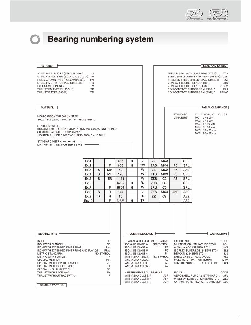
o Bearing numbering system
RETAINER SEAL AND SHIELD
STEEL RIBBON TYPE (SPCC,SUS304): J TEFLON SEAL WITH SNAP RING (PTFE): TIS STEEL CROWN TYPE (SUS42OJ2,SUS304): W STEEL SHIELD Win-I SNAP RING (SUS304): ZZS RESIN CROWN TYPE (POLYAMIDE66): TW PRESSED STEEL SHIELD (SPCC,SUS304) : ZZ STEEL RIVET TYPE (SPCC,SUS304): RJ CONTACT RUBBER SEAL (NBR) : 2RS FULL COMPLEMENT : V CONTACT RUBBER SEAL (FKM) : 2RS-V THRUST FM TYPE (SUS304): TP NON·CONTACT RUBBER SEAL (NBR) : 2RU THRUST F TYPE(C3I504): TO NON-CONTACT RUBBER SEAL (FKM) : 2RU-V
I MATERIAL I I RADIAL CLEARANCE I
HIGH CARBON CHROMIUM STEEL STANDARD: C2, CO(CN), ca. 04, C5
SUJ2, SAE 52100. 10OCr6········NQ SYMBOL MINIATURE: MC1 O-spm
MC2 3-8pm
STAINLESS STEEL Mea 5-10pm
KS440(ACD34), X85Cr13(d:iii25&D;:ii52mm Outer & INNER RING} MC4 8-13pm MC5 13 ..... 20pm
SUS44OC, AISI44QC, X102CrMo17 MC6 20 ..... 28pm (OUTER &. INNER RING EXCLUDING ABOVE AND BALL)
STANDARD METRIC •••••••• H MR, MF, MT AND INCH SERIES "S
I Ex.1 686 H J z:z. MC3 SRL Ex.2 F 608 H 1W 2RS MC4 P6 SRL Ex.3 S MR 52 W z:z. MC2 P5 AF2 Ex.4 S MF 128 W TIS MC3 P6 SRL Ex.5 S ER 1458 W ZZS CO A3 SRL Ex.6 6205 H RJ 2RS C3 SRL Ex.7 F 6706 H W 2RU CO SRL Ex.8 S R 144 J ZZS MC4 ASP AF2 Ex.9 S R 10 RJ z:z. C2 AV2 Ex.10 F 3-8M H TP AF2
BEARING TYPE TOLERANCE CLASS WBRICATION
INCH: R 'RADIAL &. THRUST BALL BEARING EX. GREASE CODE INCH WITH FLANGE: FR ISO &. JIS CLASS 0: NO SYMBOL MUL TEMP SRL (MINIATURE STD) : SRL INCH WITH EXTENDED INNER RING: RW ISO &. JIS CLASS B: P8 ALVANIA NO.2 (STANDARD): AV2 INCH WITH EXTENDED INNER RING AND FLANGE: FRW ISO &. JIS CLASS 5: P' ISOFLEX SUPER LDS18 (SEMI STD): SL8 METRIC STANDARD: NO SYMBOL ISO &. JIS CLASS 04: P' BEACON 325 (SEMI Sm): 832 METRIC WITH FLANGE: F ANSIIABMA ABEC1: NO SYMBOL SHELL CASSIDA RLS2 (FOOD) : RL2 SPECIAL METRIC: MR ANSIIABMA ABEC3: K3 MOL YKOTE 44M (HIGH TEMP) : M.M SPECIAL METRIC WITH FLANGE: MF ANSIIABMA ABEC5: M KRYTOX 240AC (ULTRA HIGH TEMP) : K2. SPECIAL METRIC THIN TYPE: ET ANSIIABMA ABEC7: A7 SPECIAL INCH THIN TYPE: ER THRUST WITH RACEWAY: FM ·INSTRUMENT BALL BEARING EX. OIL CODE THRUST WITHOUT RACEWAY: F ANSIIABMA CLASS3P: K3P AERO SHELL FWID 12 (STANDARD): AF2
ANSIIABMA CLASS5P: MP WINDSOR LUBE L-245X (SEMI STD) : WL2 ANSIIABMA CLASS7P: A7P ANTIRUST P2100 (HIGH ANTI CORROSION) :002
BEARING PART NO_
3

I
o Doign and characterl8tIC8 of radial ball bearings
......."" ... cr __
o Bearing material
4

,-~
- -~, .. ~, .. -
-- ...... , .. -o Type and characterillticB of cages,
shields and leals
,--.,",'. ) /-; ,; _. - ,
5

o 3 CD ::::J III 0" ::::J
o f!7£b .;·-'.';:].'~'Jc.,!.!.,""'~i'j
Tolerance, class, chamfer dimension of bearings
TOLERANCES OF INNER RING ANO OUTER RING WIOTH (ISO)
d(nwn) .... •• v •
P4 PO PO
V ..
PO P4 PO PO P. P4 Dlmn8terMll'l. Diameter aerlee Diameter aerte. Diameter serlee Diameter MI'Ia8 PO PO PO P4
0,2,3 7,8,8 0 2,' 7,8,9 0 2,' 7,8,9 0,2,3 7,8,9 0,2,3
""" IncL .... '- '""- Lowe. Lowe. Upper Lower Max. Max. Max. Max. Max. Max. Max. Max. 0.0(1) 2.' 0 8 7 • -4 0 4 10 8 0 9 7 • • 4 4 • 0 • • 2
2.5 10 0 -8 -7 -. -4 0 -4 10 8 6 9 7 5 5 4 4 • 6 5 • 2 10 18 0 -8 -7 -. -4 0 -4 10 8 8 9 7 • 5 4 4 • 8 5 • 2 18 3D 0 -10 -8 -6 -5 0 -5 13 10 8 10 8 6 6 5 5 4 8 6 • 2.5 3D 50 0 -12 -10 -8 -6 0 -6 15 12 9
" 10 8 8 6 6 5 9 8 4 3
Remarks1. The upper value of the bore diameter In this table IS n01 applicable when the distance from the bearing ring face IS less than 1.2 times the chamter dimensIOn rsmax Remarka2: According to the revision of ANSI/ABMA Std.20-1996 ,the cIasees ABECI • ABEC3 • ABEC5 • ABEC7 are equivalent to CLASSO·CLASSS·CLASS5·CLASS4.
TOLERANCES OF OUTER RING (ISO)
D(mm) "- "'" Vo," """"" PO PO PS P4
P4 0_ Soal Open
S,,", 0_ 0_
PO PO PO PO Shield Shield PO PO P. P4 -""- Diameter sarlas Diameter aerie. Diameter aerIee Diameter aerIee 0,2,3 7,8,9 0 2,' 2,3 7,B,8 0 2,' 2,' 7,8,9 0,2,3 7,8,51 0,2,3
""" InoL ""'I"" Lowe. Low. f.o-, ""'" lowo. Max. Max. Max. Max. Max. Max. Max. Max.
2.5(1) 8 o -e -7 -5 -4 0 -4 10 8 6 10 9 7 5 9 5 4 4 • 8 5 • 2 6 18 o -e -7 -5 -4 0 -4 10 8 6 10 9 7 5 9 5 4 4 • 6 5 3 2
18 3D o -9 -8 -8 -5 0 -5 12 9 7 12 10 8 8 10 8 5 5 4 7 8 3 2.5 3D 50 o -11 -9 -7 --i! 0 -0 14 11 8 18 11 9 7 ,. 7 5 8 5 8 7 4 3 50 80 o -1 -11 -9 -7 0 -7 16 13 10 20 14 11 8 16 9 7 7 5 10 8 5 3.5
Remarks1. The lower value 01 the outside diameter In this table Is not applicable when the distance from the bearing ring face Is less than 1.2 dmes the chamfer dimension rsmax Remarks2: According to the revision of ANSlfABMA Std.20-1996,the classes ABEC1·ABEC3·ABECS·ABEC7 are equivalent to CLASSO·CLASS6·CLASS5·CLASS4.
TOLERANCES OF INNER RING ANO OUTER RING WIOTH(ABMA) Unit pm
d(nvn) .... •• v+ v .. .u..(6c.) VB. "" So "" Single bearing
ABEC5P ABEC5P ABEC5P ABEC5P ABEC5P ABEC ABEC ABEC ABEC ABEC ABEC ABEC ABEC ABEC7P ABEC7P ABEC7P ABEC7P ABEC7P 5P 7P 5P 7P 5P 7P 5P 7P
""" InoL Upper Lowe. UP .... Low. Max. Mo><. UP .... Lowe. Max. Max. Max. Max. Max. Max. Max. Max. 10 0 S 0 5 2.5 2.S 0 25 5 2.S 3.S 2.5 7 3 7 3
10 18 0 -5 0 -5 2.5 2.5 0 -25 5 2.5 3.5 2.5 7 3 7 • 18 3D 0 -5 0 -5 2.5 2.5 0 -25 5 2.5 3.5 2.5 7 3 7 •
Remar1<sl. ABECSP and ABEC7P are the tolerance classes tor hlgn precision bearings.
LIMIT TOLERANCE VALUES (METRIC) OF CHAMFER DIMENSIONS OF RAOIAL BEARINGS
Unil·mm
rsmln d(mm) r.mu: romax
Qve. Incl. Radial Axial D.OS - 0.10 0.20 0.05 D." - 0.16 0.30 0.08 0.10 - 0.20 0.40 0.10 D .• - 0.30 0.60 D1S 0.20 - 0.50 0.80 0.20 D.3D - 40 0.80 1.00 0.30 D.3D 40 0.80 1.00 0.30 D." - 40 1.00 2.00 0.60 D." 40 1.30 2.00 0.60 1.00 - 50 1.50 3.00 1.00 1.00 50 1.90 3.00 1.00 1.10 - 120 2.00 3.50 1.00 1.10 120 2.50 4.00 1.00 1.50 120 2.30 4.00 1.50 1.50 120 3.00 5.00 1.50
d : NomIMl bon! dlMl.wr Atbtrp : Slngl. p .... m..., bo ... dl.,.,.. -Ivh : Dwllllion of. "ngI. bo ... dl ....... V41 : Ben dlam .... YllrIIIIIon In a RIg"
radi" pi.,. YtIIItp : M..., bo ... dl.,.,.. varIatIan A -.(Aeo) : Dl¥illlion of the .Ing" inn .. and out.
ring width tram the namlllll dlrnllllllan Yao(VOo) : Yarilliion or thIt inn .. and out. ring width Iaa : Rw:IIIII rwlaut of ..... bIed '-1ng
i'1ll .. ri1g Sd : FaCII runaut willi bon! BiG : "-mblld bArIng inn.- ring -r.c. runaut -....... D : Nomllllll aulllcl. dl.,.,.. ADM, : Slngl. p .... m..., autalde dI ....... -. A Do : Devllllion of a IIngi. aublde dlanwter
YD, : Oullid. d~r vanldlon ~ a slngl. ..... pI ••
Yor.p : MIlan aublde dlam .... varIatIan K- : FIM:Ilai runaul of _mbled bNrtng .......'" So : Variation at aubide ....,.. gll'lll'lllrix
Incllndan with r.a. Seu : AlMmbllld bMring out. ring r.a. rwlaut --Yeo. : VarIation at III. out. ring width ADio : fling. aublde dlanwter dIIwIatIan Aa. : fling. width d..n.tian
r.mill : Smal'-l: PIInnillibie -11IiI" chamfer dlll'lllnMIntralnftlJm Ilmll)
d : Noml_ ba ... d~r r..-.:x : IMgIIIt p8m1 .... b .. RIg" ctI"""r
dlll'lllnMIntnulmum IlmlQ r QIII/U: IMgIIIt p8m1 .... b .. Ulg .. 1IhIIII and
hDUllng nil. redlu.
NuII(1) : n. 'MkI. III r""", In DlIII dlrwctlon or bMrIng wtth IIDnWI" wlcfth III undsr t... .. th. __ IMoll8ln ~ dbctlon
6

f!1£CJ SffllfJ "-=.'.tL'.:i {,'!.!. '=-';';i.~J ~",~,.") ,,-'!c';l~'J J~'.U,·L'.l
Unit,um
t.a.(.6.c.)1II Y&(Vc.) III ... ... ... d(mm)
SIngle bearing Inner/outer ring Inne ring
PO PO PO P6 P. .. PO .. P. .. PO P4 PO P. P5 P4
U .... '""- Lowe. Max. Max. Max. Max. Max. Max. Max. Max. Max. Max. Max. Max. a- IncL
0 40 40 12 12 • 2.' 10 • 4 2.' 7 3 7 3 0 .• (1) 2.' 0 -120 -40 ,. ,. • 2.' 10 6 4 2.' 7 3 7 3 2.' 10 0 -120 - .0 20 20 • 2.' 10 7 4 2.' 7 3 7 3 10 1. 0 -120 -120 20 20 • 2.' 13 8 4 3 8 4 8 4 18 30 0 -120 -120 20 20 • 3 ,. 10 • 4 8 4 8 4 30 50
.. Nate (1). O.6mm IS Included In this classification . Note (2): The inner ring width variation is the same for the outer ring of the same bearing size.CLASS5 and CLASS4 referring to outer ring only.
Unit.urn
"- SD S- Va." Flanged type Aangadtype
O(mm) ""- d(mm) .'" PO PO P5 P4 PO P4 P5 P4 P' P4
PO PO P' P4 PO P. P' P4
Max. Max. Max. Max. Max. Max. Max. Max. Max. Max. a- InoI. U_ l.oww UP .. Lowe. a- InoI. Upper Lowe. U_ Lowe. ,. 8 • 3 8 4 ,. 8 • 3 8 4 ,. 9 • 4 8 4 20 10 7 • 8 4 25 13 8 • 8 4
Note (1) Size 2.Smm III Included In thiS classification. Note (2) Applicable without locating snap ring.
8 • • 2.' -8 • • 2.' 10 8 • • 2.' 18 8 • • 2.' 30 10 • 6 3 50
10 H2O -36 0 -36 0 .• 2.' 0 -40 0 -40 18 H7D -43 0 -43 2.' 10 0 -120 0 -40 30 +330 -52 0 -52 10 18 0 -120 0 -60 50 +390 --il2 0 -62 18 30 0 -120 0 -120 80 +460 -7' 0 -74 30 50 0 -120 0 -120
Note (3) The outer ring wldltl vartlllions tor CLASSO and CLASS6 are the same as for the Inner ring of the same bearing size.
TOLERANCES OF OUTER RING (ABMA) UnH.um
... Vnp,VDmp L:.B.(..-.c.) Va.- So "'" S- Flanged type
O(mm) '-Opon
ABEC .8EC ABEC ABEC --5P,7P 5P 7P 51',7P 5P 7P a- InoI. I.\lPO" '- ..... r U,... '- '-
18 0 • • 0 • • 18 30 0 -e -. 0 --6 -. 30 50 0 -e -. 0 --iI -. . .
Note (1). Applies to ftange width vanalion of flanged bearing . Note (2): Applies to ftange back face.
.~ ....
I
ring face of outer or inner ring
rsmax axial direction
rsmin
rsmin
ring bore or outside cylindrical surface
SeaI,Shilid ABEC -"""'" 5P,7P ABEC ASEC ASEC ABEC ABEC ASEC ABEC -ABEC ASEC 0,," ... ABEC5P 51' 7P 5P 7P 51' 7P 51' 51',7P 5P 7P ... ABEC7P
I.\lPO" '- '- .... .... Up".. '- .... .... .... .... .... .... .... +1 --6 6 2.' • 0 25 • 2.' • 4 • 3.' +1 -7 -8 2.' • 0 -25 • 2.' • 4 e • +1 -7 -6 2.' • 0 -2' • 2.' 8 4 e 4
rs min..smallest permissible single chamfer dimension (minimum limit)
rs max=largest pennissible single chamfer dimension (maximum limit)
ra max=largest permissible single shaft and housing fillet radius
8 8 8
- .""ro "-,, ASEC ABEC5P ABEC5P ABEO A9EC
7P ABEC7P ABEC7P " 1P .... ,.. e- ,.. e- .... ....
• 0 -25 0 -51 7.' 5
• 0 -25 0 -51 7.' 5
• 0 -25 0 -., 7.' •
NOTE: The exact shape of the chamfer surface is not specified, but its contour in an axial plane shall not be allowed to project beyond the imaginary circular are, of radius rsmin , tangential to the ring face and the bore or outside cylindrical surface of the ring (see figure).
7
c 3 CD ::::J en o ::::J
o @f) .;=J."'J""'-'-'-"'.~.cJ
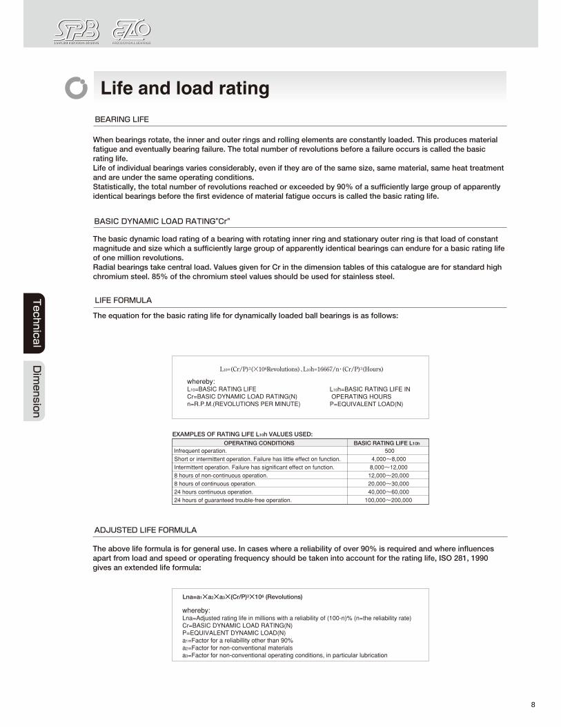
Life and load rating
BEARING LIFE
When bearings rotate, the inner and outer rings and rolling elements are constantly loaded. This produces material fatigue and eventually bearing failure. The total number of revolutions before a failure occurs is called the basic rating life. Life of individual bearings varies considerably, aven if they are of the same size, same material, same heat treatment and are under the same operating conditions. Statistically, the total number of revolutions reached or exceeded by 90% of a sufficiently large group of apparently identical bearings before the first evidence of material fatigue occurs is called the basic rating life.
BASIC DYNAMIC LOAD RATING"Cr"
The basic dynamic load rating of a bearing with rotating inner ring and stationary outer ring is that load of constant magnitude and size which a sufficiently large group of apparently identical bearings can endure for a basic rating life of one million revolutions. Radial bearings take central load. Values given for Cr in the dimension tables of this cataloguB are for standard high chromium steel. 85% of the chromium steel values should be used for stainless steel.
LIFE FORMULA
The equation for the basic rating life for dynamically loaded ball bearings is as follows:
Lw-(Cr /P)3(XIlJ6Revolutions), lloh-l6667 In' (Cr /p)5(Hours)
whereby: L10=BASIC RATING LIFE Cr",BASIC DYNAMIC LOAD RATING(N) n.R.P.M.(REVOLUTIONS PER MINUTE)
EXAMPLES OF RATING UFE bah VAWES USED"
OPERATING CONDITIONS Infrequent operation.
Ll0h",BASIC RATING LIFE IN OPERATING HOURS P.EQUIVALENT LOAD(N)
BASIC RAllNG UFE L10h 500
Short or intermittent operation. Failure has litHe effect on function. 4.000 ..... 8.000 Intermmen1 operation. Failure has significant ellect on function. 8.000 ..... 12.000 8 hours of non-contlnuous operadon. 12.000 ..... 20.000 8 hours of continuous operation. 20.000 ..... 30.000 24 hours continuous ODeration. 40.000 ..... 60.000 24 hours of guaranteed trouble-free operation. 100.000 ..... 200.000
ADJUSTED LIFE FORMULA
The above life formula is for general use. In cases where a reliability of over 90% is required and where influences apart from load and speed or operating frequency should be taken into account for the rating IHe, ISO 281, 1990 gives an extended IHe formula:
Lna=a, xazXa.X(CrIP)3X1 (]I (Revolutions)
whereby: Lna=Adjusted rating life in millions with a reliability of (10o-n)% (n",the reliability rate) C,.BASIC DYNAMIC LOAD RATING(N) P=EQUIVALENT DYNAMIC LOAD(N) a,.Factor for a reliabillity other than 90% Cl2=Factor for non-conventional materials aa-Factor for non-conventional operating conditions. in particular lubrication
8

(1) RELIABILITY FACTOR a, When a reliability of over 90% is required, the corresponding factor should be selected from the following table .
• RELIABILITY FACTOR 81
Reliability
.,
(2) MATERIAL FACTOR ... Improvement in manufacturing techniques for raw material and for heat treatment of components have led to an extended fatigue life for bearings. Our standard bearing material is a superior quality of vacuum degassed steel leading to an extended life for bearings. The basic load ratings given in this catalogue have besn established by taking this longer life into consideration. This gives an increase in the operating life in hours of a factor of 2.2 and a factor of 1.3 for the load canying capacity. The material factor 112=1.
(3) OPERATING CONDITIONS FACTOR '"
This is an adjustment factor to meat non-conventional operating conditions for lubrication, temperatura and load. Under good lubrication conditions with a pennanent oil film between rolling elements and rings, the factor 83=1. In unfavourable condHions (dm· n ;S 10,000), a factor"" < 1 must be selected.dm = mean bearing diameter = (D+dY2 , n = operating speed. At temperatures above 12Ot, greater dimensional changes occur and the material hardness deteriorates which affects the bearing life. The operating factor It for temperature can be taken from the following table:
.OPERATING TEMPERAlUREAND LIFE COMPENSATION FACTOR It
BEARING 120 150 175 200 225 250 275 300 TEMPERATURE{t:)
TEMPERATURE 1.00 0.90 0." 0.75 0.65 0.60 0.52 0.45 FACTOR(ft)
.. Heat stabilized bearmgs. where the dimenSions are stable above 120t. are available on request.
BASIC STATIC LOAD RATING "Cor"
The Basic Static Load Rating applies to bearings where rotating motion does not occur or occurs only infrequently. The Basic Load Ratings and calculation methods in this catalogue are based on methods described in ISO 281 and on ISO Recommendations NR.76, taking into account the current level of bearing technology. Excessive static load causes brinelling at the contact point between the rolling element and raceway. As a standard of permissible static load, the basic load rating Cor for radial bearings is specHied as follows: Maximum contact pressure at the contact point between rolling element and bearing ring to be 4200 MPa and total permanent deformation of the bearing of appro 111 OOOOth of the rolling element's diameter. Basic Static Load Rating for stainless steel is 80% of that for standard bearing steel.
9

o 3 CD ::::J III g
07£b ';'-'-':j.'~'Jc.'!.!.2."~LJ
EQUIVALENT DYNAMIC BEARING LDAD "P"
Load condHions on bearings are usually a combination of radial and axial loads. In order to establish the equivalent radial load with definite force and diraction we usa the following formula:
.RADIAL lOAD FACTOR AND AXIAL lOAD FACTOR
FoI(ZD') • Fa/Frii1iiie faIFr>e
X y X Y 0.172 0.19 1 a 0.56 2.30 0.345 0.22 1 a 0.56 1.99 0.689 0.26 1 a 0.56 1.71 1.03 0.28 1 a 0.56 1.55 1.38 0.30 1 a 0.56 1.45 '.07 0.34 1 a 0.56 1.31 a45 0.38 1 a 0.56 1.15 5.17 0.42 1 a 0.56 1.04 6.89 0 .... 1 a 0.56 1.00
P-XFr+YFa(N) X.RADIAL LDAD FACTOR
Fr=RADIAL LOAD(N) YzAXlAl LOAD FACTOR Fa-AXIAL LDAD(N) D.BALL DIAMETER(mm)
EQUIVALENT STATIC RADIAL LDAD "Po"
For ball bearings subject to both radial and axial loads, the static radial load wHh definite force and direction is called the Equivalent Static Radial Load. The higher value from the two formula shown below should be used.
Po-O.6XFr<{l.5XFa(N), Po-Fr (N)
SAFETY MDDULUS"fs"
Permissible equivalent static load depends on basic static load rating. But using limit of bearing charge by using condHion. Accordingly we use safely modulus which is experimental value.
fs=Cor/Po Is·SAFETY MODULUS Cor=BASIC STATIC LOAD RATING(N) P.,..EQUIVALENT STATIC RADIAL LOAD(N)
USING CONDI110N Is NORMAL OPERATION 1.0 SHOCK LOAD 1.5 SILENT AND HIGH ACCURATE ROTATION '.0
10

o 01ih ~yj~~ ,,-,'.cL",;! o:,'!.!. '=-';';i.~J ~"'~,.") ,,-'''''l~'' l~'.U,'L'.l
Fitting of bearings
THE IMPORTANCE OF CORRECT FITTING
A bearing can only perfonn to Hs full capacity when it is correctly fitted on the shaft and in the housing. Insufficient interference on fitting surfaces could cause bearing rings to creep in a circumferential direction. Once this happens, considerable wear occurs on the frtting surface and both shaft and housing are damaged. Furthennore, abrasive particles may enter the bearing causing vibration, excessivB heat and damage to raceways. It is therefore necessary to provide bearing rings under rotating load with an adequate interference lit to prevent creep. When using thin-type bearings under low load, the bearings should belestened by a nut. Statically loaded bearings generally do not nBed to be litted with an interference ftt. Only when subject to a high degree 01 vibration do both inner and outer rings require fitting wHh an interference fit.
eFmlNG OF BEARING AND SHAFT
CONDITION SHAFT BORE SHAFT TOLERANCE
CLASS (STEEL SHAFT) DIAMETER
TI-IINTYPE OTI-IERS LIGHT LOAD<- 10:5id:i018 h5 ~
INNER RING O.06CrOR 18~d~30 h5 iSS ROTATING LOAD FLUCTIJATING LOAD 30::i!d:i!50 h5 IsS
OR STANDARD 10~d:;;18 ~ ~ INDETERMINATE LOAD=O.06- 18:i!d:i!30 LOAD DIRECTION O.12Cr 30;:$d:iii.50 iSS k5 NECESSARY FOR INNER RING ALL BORE 05 O. TURNING EASILY DIAMETERS
OUTER RING AROUND SHAFT ROTATING LOAD UNNECESSARY
FOR INNER RING ALL BORE h5 h6 TURNING EASILY DIAMETERS AROUND SHAFT
.FITTING OF BEARING AND HOUSING
AXIAL TOLERANCE CLASS OF CONDITION DIRECTIONAL SHAFT HOUSING SEATS
(ONE-PIECE HOUSING) MOVEMENT OF OUTER RING THIN TYPE OTHERS
VARYING LOADS EASY TO MOVE H6 H7 LlGIfTOR
EASY TO MOVE H7 H8 STANDARD LOAD HIGH TEMPERATURE EASY TO MOVE G. G7
INNER RING OF INNER RING AND SHAFT ROTATING LOAD ASARULE,
LIGHT OR STANDARD IMPOSSIBLE K5 K6 LOAD PRECISE ROTATION TO MOVE
POSSIBLE TO MOVE JS6 J8 QUIET OPERATION EASY TO MOVE H. H.
LlGIfTOR IN GENERAL,
STANDARD LOAD POSSIBLE J .. J7 TO MOVE
STANDARD OR ASA RULE, INDETERMINATE HEAVY LOAD IMPOSSIBLE K5 K7 lOAD DIRECTION TO MOVE
LARGE SHOCK LOAD IMPOSSIBLE M5 .. 7 TO MOVE LlGIfTOR IMPOSSIBLE M5 .. 7 FLUCTUATING LOAD TO MOVE
STANDARD OR HEAVY LOAD IMPOSSIBLE
N5 N7 TO MOVE OUTER RING
THIN-TYPE HOUSING SEATS ROTATING lOAD IMPOSSIBLE HEAVY LOAD OR LARGE TO MOVE P. P7 SHOCK LOAD
11

, / ,~/'/j --- ...... _--
- - , .. --.
CllLCULA1u.Of ~
(')FITT1"~_IIEMD~ I,DtlALOIWI' 'OFlr.lEIIINGCU'I'BI_ 1100111"''''''_ ,.' , 10 IE'd .... _ II.. ' ___ .... ..... _ ... _ •••• _ ..... ___ • 00"_" ___ "-h '_., .... __ .... __
(I) LOIID(X'''' a, L leE _.,,"'=wtlol_lIIOIl_rRi ' • ___ ._" __ .h"oI_IIIIIIIII_~ .. 1o "In .o,.. eM ft' ---_ .. __ ... _-_ .. -.
1 __ .. __ 11_ •• ___ ••• ___ -.. __ •• _
12

(J1£b 5iflZ!J "-=.'.t;,'.d{,'!.!.c=.";;ihJ :."'''}J,,-'-·;,:L'".·lj~'.'1·I';
(4) EFFECTIVE INTERFERENCE, SURFACE ROUGHNESS AND ACCURACY
The surface roughness is smoothed during fitting and the effective interference becomes smaller than the theoretical interference. The surface roughness quality of a mating surface has an influence on how much this theoretical interference decreases. Effective interference can usually be calculated as follows:
Ground Shaft: 6.d=d1(d+2)'Ad~mm) Turned Shaft: .o.d=dI(d+3)oAda mm) .6.d : EFFECTIVE INiER~ERE CE(mm) .6.da : THEORETICAlINTERFERENCE(mm) d : NOMINAL BORE DIAMETER OF BEARING(mm)
By combining these factors, the theoretical interference fit required for inner ring and shaft where the inner ring is subjected to rotating load is calculated as follows:
Adaii:;(AdF+6dT) «d+3)1d or (d+2)/d) (mm)
Normally, shaft and housing seats have to meet the accuracy and roughness requirements as given below .
• ACCURACY AND ROUGHNESS OF SHAFT AND HOUSING SEAlS
SHAFT HOUSING
BELOW 50% OF SHAFT BELOW 50% OF ROUNDNESS HOUSING BORE DIAMETER TOLERANCE DIAMETER TOLERANCE
BELOW 50% OF SHAFT BELOW 50% OF HOUSING BORE CYLINDRICITV DIAMETER TOLERANCE
WITHIN BEARING WIDTH DIAMETER TOLERANCE WITHIN BEARING WIDTH
saUARENESS :ii3l10OO(O.17°)
ROUGHNESS OF MATING Rmax3.2 Rmax6.3 SURFACE
Mounting bearings with extra tight or light interference fits can lead to eariy bearing failure. In order to ensure safe operating conditions the tolerance variations of shaft seats, housing bores and bearing bore and outside diameter need to be reduced. We recommend the tolerance zones are divided into two bands and selective assembly is applied. Bearings sorted into two tolerance bands for inner and outer rings are available on request. These bearings are marf<ed as follows:
esELECTIVE CLASSIFICATION OF OUTER AND BORE DIAMETER TOLERANCES AND INDICATION MARK
~TOLERANCE OF BORE 0 .... -012 -DJ2 .... -D DIAMETER
TOLERANCES OF OUTER MARK 1 2 DIAMETER
O .... _d/2 1 C11 C12
-dI2 .... -d 2 C21 ~ C22 ~ O .... -d 0 C01 ( ZC2 ) CO2
NOTE: 1.THIS IS APPLIED TO BOTH BEARINGS OF ABEC5P AND P5.
O-·D
0
C10
C20
2.UPON YOUR REQUEST, PLEASE SPECIFY THE MARK LISTED BELOW. ZC1 .... 2 SELECTIVE CLASSIFICATIONS FOR BORE DIAMETER
TOLERANCE (0-·d/2, .d/2--d) 1 SELECTIVE CLASSIFICATION FOR OUTER DIAMETER TOLERANCE (O ...... -D)
2C2 .... 1 SELECTIVE CLASSIFICATION FOR BORE DIAMETER TOLERANCE (O-·d) 2 SELECTIVE CLASSIFICATIONS FOR OUTER DIAMETER TOLERANCE (O ..... -D/2~ -D/2 ..... -D)
ZC3 ... 4 SELECTIVE ClASSIFICATIONS FOR BOTH BORE AND OUTER DIAMETER TOLERANCE (O-·d/2-.·d/2--d,O-·DI2-,·DI2-·D)
D .... MINIMUM VALUE OF OUTER DIAMETER TOLERANCE d .... MINIMUM VALUE OF BORE DIAMETER TOLERANCE
13

o 3 CD ::J UI 0" ::J
o Wih ,;·-'.·;n.·~·I,'.·!.!.,""'~iiJ
Internal clearance
INTERNAL CLEARANCE AND STANDARD VALUES
Internal clearance is the play between outer ring, inner ring and rolling element. Generally. the amount of up and down movement of the outer ring with respect to the fixed inner ring is called the radial internal clearance and ita right and lett movement the axial internal clearance. Bearing internal clearance in operation is an important factor that has a significant inftuencB on other factors such as noise, vibration, heat and fatigue life. Radial ball bearings are usually classified by their internal radial clearance. When measuring the internal clearance, the bearing is subjected to a standard load in order to ensure full contact between all bearing components. Under such a load, the measured value is larger than the actual value stated for radial clearancej this is due to elastic deformation. The difference is compensated by the factors given in the tables below .
• RADIAL INTERNAL CLEARANCE OF SMAll. AND MINIATURE BEARINGS
CLEARANCE SYMBOL MC1 MC2 Mea
I min 0 3 5 CLEARANCE
I max 5 8 10
NOTE: 1.STANDARD CLEARANCE IS Mea.
MC4
8
13
BEARING INTERNAL CLEARANCE
RADIAL INTERNAL CLEARANCE
MCS
13
20
AXIAL INTERNAL CLEARANCE
UnltlJm
MCO
20
28
2.FOR MEASURING CLEARANCE, OFFSET BY COMPENSATION FACTOR LISTED BELOW.
CLEARANCE SYMBOL
OOMPENSATIONF~R
.RADIAL INTERNAL CLEARANCE OF STANDARD RADIAL BAll. BEARINGS
NOMINAL BORE CLEARANCE DIAMETER d(mm) C2 CN(eo) ea OVER INCL. MIN MAX MIN MAX MIN MAX
10(ONLY) 0 7 2 13 8 23
10 18 0 • 3 18 11 25 18 24 0 10 5 2ll 13 28 24 30 1 11 5 20 13 28 30 40 1 11 6 20 15 33 40 50 1 11 6 23 18 36
MEASURING LOAD IS AS FOLLOWS. MINIATURE BEARINGS 2.5N (0.25kgf) SMALL BEARINGS 4.4N (0.45kgf)
Unit ~m
C4 CO MIN MAX MIN MAX 14 2. 20 37
18 33 25 45 20 38 28 48 23 41 30 53 28 46 40 64 30 51 4. 73
NOTE: 1.FOR MEASURING CLEARANCE, OFFSET BY COMPENSATION FACTOR LISTED BELOW.
Unit I-Im BORE DIAMETER OF
MEASURING LOAD OOMPENSATIONF~R NOMINAL BEARING d(mm)
OVER I INCL N (kgf) C2 I CN(CO) I C3 I C4 I CS 100NCWDED) 18 24.5(2.5) ..... 4 4 4 4 4
18 50 48(5) 4-5 6 6 6 6
14

(J1£b 5iflZ!J "-=.'.t;,'.d{,'!.!.c=.";;ihJ :."'''}J,,-'-·;,:L'".·lj~'.'1·I';
RELATIONSHIP BETWEEN RADIAL INTERNAL CLEARANCE AND AXIAL INTERNAL CLEARANCE
The axial internal clearance is established from the ball diameter, outer and inner ring raceway radius and the radial internal clearance. Usually it is about 1 0 times the value of the internal radial clearance. Selection of a small internal radial clearance or an extra large interference fit in order to reduce the internal axial clearance after mounting is not recommended.
30
RADIAL CL.EARANCE:Ar (",m)
SELECTION OF BEARING CLEARANCE
40
0.600 1.000 1.588 2.000 2.778 3.500 '.762 6.350 7.144 8.731 10.319 11.906
Aa:AXIAL INTERNAL CLEARANCE(mm) ro:OUTER RING RACEWAY RADIUS(mm) Da:BALL DIAMETER(mm) Ar:RADIAL INTERNAL CLEARANCE(mm) n:INNER RING RACEWAY RADIUS(mm)
Theoretically, maximum bearing life is with very slight preload. However, even a slight increase in this theoretical preload can have a considerably detrimental effect on the bearing lile. Positive clearance should therelore be selected. Me3 is usually used for miniature or small bearings, standard clearance for general bearings and the clearance for thin section bearings should never be greater than -standard" .
• SELECTION OF RADIAL INTERNAL CLEARANCE
OJ*8ling Condition Clearance Clearance fit for inner and outer ring. Low axial load. No axial load carrying requirement.
MC1.MC2.C2 Select bearing with reduced radial clearance. Lower vibration and noise. Low speeds.
Lower frictional torque. Standard axial load. Average axial load carrying requirements. MC3.MC4 .. CN(CO) Slight interference fit for inner ring. Clearance fit for outer ring. Averagellow speeds.
Extremely low frictional torque. High axial load. High axial load carrying requirements. Heavy interfence fit to support high loads or shock loads. Large temperature gradient from inner MCS.MCB .. C3 .. C4.CS ring to outer ring. High degree of shan deflection.
CALCULATION OF CLEARANCE
OF
b.l:IN!I1ALClEARANCE
...
(1) RUNNING CLEARANCE Running clearance is the resultant clearance after load, temperature difference and fitting are taken into consideration.
(2) CLEARANCE REDUCTION BY TEMPERATURE DIFFERENCE BETWEEN INNER AND OUTER RING
In a bearing, the highest temperature is generated in the rolling element followed by the inner ring, with the outer ring having the lowest temperature. Since it is impossible to measure the temperature of a rolling element, in practice, the temperature of the inner ring is used.
8t"aX.TXDo(mm)
15

o 3 CD ::::J III o ::::J
o
(3) CLEARANCE REDUCTION BY FITTING
When a bearing is fitted onto a shaft or into a housing with an interference fit, the internal clearance of the bearing reduces.
8f-8fi+8fu-& dbX d/dbX ((l-(do/ d)'» / (l-(do/db)'»+ &DaXDa/DX ((l-(D!Dh)')/(l-(Da/Dh)'» (mm)
(4) CLEARANCE INCREASE BY LOAD Load on a bearing defonns it elastically and increases the internal clearance.
8w=eX((5XFr)/(ZXro. a »""'X(l!dw)(lI3) (mm) The initial contact angle ao is calculated from the following two formulae: COB Qo/coe a -l+C/(2Xm-l)x CFaI(9.8XZX0w2xsin a)(2/3) l-coe ao-Ar/(2XDWX(2Xm-l»
SYMBOLS
~T, 'rnMPERATIJRE DIFFERENCE BE'IWEEN INNER AND OUIERRING
0., OUIERRING RACEWAYDIAME'ffiR
~dh, ClEARANCE OF INNER RING ON SIIAFT do, BORE DIAME'ffiR OF HOu.oW SIIAFT
Dn, OlITSlDE DIAME'ffiR OF HOUSING SEAT ~Do, ClEARANCE OF OUIER RING IN HOUSING
m, OSCUlATION
Z, NUMBER OF BAIlS
Ow, BALLDIAME'ffiR
a, CONTACT ANGLE
a., INIfIAL CONTACT ANGLE
Fa: AXlAL WAD
Fr, RAOIALWAO
dh,
Do, AVERAGE OlITSlDE DIAME'ffiR OFINNER RING
AVERAGE OlITSlDE DIAME'ffiR OF OU'rnR RING
~" RAOIALIN'ffiRNALClEARANCE C, MA'rnRlALELASIICrIYFACTOR
., COEFFICENTOF11IERMALEXPANSIONFOR BEARING S'rnEL
Lubrication
OBJECT OF LUBRICATION
I General BNI"Ing I C=O.00218 I m=O.525 I
[Instrument Bearing j C=O.00287 j m=O.560 I
The lubrication method and the lubricant have a direct effect on the bearing life; the moat suitable lubrication must therefore be selected for each application. Effects of lubrication are described as follows:
(1) DECREASE OF FRICTION AND ABRASION
It decreases rolling friction between the raceway and the rolling elements, sliding friction between rolling element and cage and sliding friction of guide surface between the cage and the bearing ring.
(2) REDUCTION OF HEAT GENERATION
It dissipates heat generated inside the bearing as well as heat conducted from the outside thus preventing overheating of the bearing and deterioration of the lubricant.
(3) PROTECTION FROM CORROSION AND CONTAMINANTS It prevents corrosion of rolling elementa, bearing rings and cages and also prevents the ingress of contaminants and moisture into the bearing.
16

REQUIRED CHARACTERISTICS DF THE LUBRICANT
(1) LOW FRICTION AND ABRASION
(2) HIGH STABILITY AGAINST HEAT, GOOD THERMAL CONDUCTIVITY
(3) STRONG OIL FILM
(4) NON-CORROSIVE
(5) PROVIDE A GOOD BARRIER AGAINST DUST AND MOISTURE
(6) MAINTAIN A STABLE VISCOSITY
STANDARD LUBRICANT
lubricant B""'" ElO
CODE Manufacturer MIL STANDARD
sm.GREASE MULTEMPSRL SRL K odoYushi
ALVANIA2S AV2 Shell OIL Co.
1l1£() SffljjJ "-=.'.tL'.:i {,'!.!. '=-';';i.~J ~",~,.") ,,-'!c:;l~'J J~'.U,·L'.l
Operating _n. T.mperatuN(C) gravity
-40 ..... +150 0.93 -25 ..... +120 0.92
STD. OIL AERO SHEll. FLUID 12 AF2 Shell OIL Co. MIL-PRF-6085D -50 ..... +205 0.93
LUBRICATION METHOD
There are two types of lubricant: oil or grease. It is important to select the conrect lubricant and lubrication method for each application and its conditions.
eWBRICATING OIL AND GREASE
WBRICAllNG OIL LUBRICATING GREASE
ROTATING SPEED LOW' MEDIUM' HIGH SPEED LOW • MEDIUM SPEED
LUBRICANT EFFICIENCY EXCELLENT GOOD
COOLING EFFECT GOOD NONE
TORQUE COMPARATIVELY LOW COMPARATIVELY HIGH
LUBRICANT LIFE LONG COMPARATIVELY SHORT
LUBRICANT REPLACEMENT EASY DIFFICULT
LUBRICANT LEAKAGE SHOULD NOT BE USED WHERE OIL LEAKAGE IS LITTLE GREASE UNACCEPTABLE
IMPURITIES FIL TRAll0N EASY
SEALING EQUIPMENT COMPLEX
.GREASE FIWNG VOLUME
SYMBOL FIWNG VOLUME(%)
M 70±10
S 50±10
G 40±10
L 30±10 Q 25±5
K 20±5
X 10±5
NOTE: LIGHT LOAD ( :iiO.06Cr) STANDARD LOAD (";0.12Cr)
LEAKAGE
DIFFICULT
SIMPLE
OPERATING CONDITION
SPEED lOAD
LOW HEAVY
LOW MEDIUM
MEDIUM MEDIUM
MEDIUM MEDIUM
MEDIUM MEDIUM
HIGH LlGIfT
HIGH LlGIfT
17

o 3' m ::::J en 0' ::::J
@0 .;'-"","",'0:.''-'."""',,,,,-,,
.CRITERIA FOR LUBRICATING OIL SELECTION OPERATING ISO VISCOSITY GRADE OF LUBRICATING OIL(VG)
TEMPERATURE OF d. BEARING ("C) MEDIUM LOAD HEAVY LOAD/SHOCK LOAD
-30 .... 0 UP TO PERMISSIBLE 15.22,32 32,48 ROTATING SPEED
UP TO 15000 32,46,68 100
15000 .... 80000 0-.60 ".46 ..
80000 .... 150000 22." .. 150000 ..... 500000 10 22,32
UP TO 15000 150 220
15000 ..... 80000 100 150 +60-+100
80000 ..... 150000 .. 100,150
150000 ..... 500000 .. .. +100 .... +150
UP TO PERMISSIBLE 320 ROTATING SPEED
NOTE. 1.IF HEAVY LOADS OCCUR AT LOW SPEEDS, A HIGHER VISCOSITY LUBRICATING OIL SHOULD BE USED. 2.THIS TABLE IS FOR OIL BATH LUBRICATION SYSTEM AND RECIRCULATING OIL SYSTEMS. 3.dn _ BEARING BORE DIAMETER d(mm) X ROTATING SPEED n(r.p.rn)
.COMMON OIL BRANDS AND EFRCIENCY
Manufacturer
Shell 011 Co .
Ap ........ Standard
• COMMON GREASE BRANDS AND EFFICIENCY
I_M_an_ulact __ u_ .... _ll~~~B~ .. ~n=d==:::t~Cad'l'1·~UIh~~I:u Age ~m~nt~=Lu=b~ri Mcan~ln.t~ ....... ~=tF ~ ~ .. I Ulhlum I Min.... tm: 275 •
Shell Oil Co.
Kyoclo Yushi
K1uber Lub.
Dow Coming Co.
IAo .. 8hol~~14~~~CO~II.I~um~~ 1148 273 ~~ l Ao .. 8hol: '.22 AG2 M",~ •• I ~ 260 275
!:::: ~ I: I~ . ~=i ::: ::::: I: 270 ~~
Ilooftax~NB52 B52 Borium 1......,,1 122 ;-., ~.
,HDS2
I I
OXIDS18'~ U UIh:um
CX2000 PI I om
LJV
~.r#
I Mo:I~~i ~i:: I Molykoto FS3451 F35 P1FE
loon.
:moon.
,. · .
· · ·
· ~~.~ ·
·
r-:..._u_pc_~_'_E_·~_ .. _---jI""' ~-;:;::;-PI: :7 Mobil Oil Co. lMObiiliX EP2
~IP~E 1)(3 I
~ Ulhlum
ShI""", Qoemlcol "" G40 lithium 811100ne I 210 260
18

o
o
Maximum permissible bearing speed
Each bearing type has its own limiting speed. The theoretical speed that bearings can run at safely, even if heat generation by internal friction occurs, is called the maximum permissible speed. The pannissible speed is related to bearing type, type of cage, lubricant type, load and cooling conditions to which the bearing is subjected. For contact rubber seals(2RS type), the permissible speeds are limited by the peripheral velocity of the seal lip. Normally, this is approximately 50 - 60% of that 01 non-contact rubber seals. II light contact rubber seals are required, this must be stipulated with the order. II high loads occur, the permissible speed values must be reduced and the lollowing supplementary lactors applied, except under standard operating condHions(CrlP<12, FalFr>0.2 )
.COMPENSATION FOR MAXIMUM PERMISSIBLE SPEED DEPENDENT ON LOAD RATIO
c,/p • • 7 • • 10 11 12
COMPENSATION 0.72 0.76 0.65 0." 0." 0.96 0." 1.00 FACTOR
.COMPENSATION FOR MAXIMUM PERMISSIBUE SPEED UNDER COMBINED AXIAL AND RADIAL LOAD
Fo/F, 0.25 0.50 0.75 1.00 1.25 1.50 1.75 2.00
COMPENSATION 1.00 0." 0." 0.91 0." 0.88 0.87 0." FACTOR
W the bearing opeoates at over 70% of the permissible speed value, a lubricant for hi\t1 speed should be selected. The valuss for the permissible speed are for applications wHh horizoo daI shafts and wHh appropriala lubrication. With __ shalls, only 80% of the maximum speed value should be used. This is necessary due to the reduced ~ guidance and reduced lubricant raIention in this type of application.
Frictional torque and temperature
FRICTIONAL TORQUE
Frictional torque of rolling bearings varies under changing load and lubrication conditions. When grease is used as a lubricant, the grease resistance must be added to the bearing frictional torque. When adequate lubrication under normal loading condHions(CrlP>12,FalFr<O.2), the frictional torque of a bearing can be expressed as follows:
19

c 3 CD ::::J en o ::::J
o
@fj >;·=J.",'J':',''-'-C'''j~.'-''
M· p' F' d/2(N'mm)
TEMPERATURE INCREASE
M:FRICTIONAL TORQUE(N'mm) F:BEARING LOAD (N) d:SHAFT DIAMETER(mm) p :=0.0015 COEFFICIENT OF FRICTION
Friction and grease resistance can increase the bearing temperature. In the initial stages of operation, the internal bearing temperature rises rapidly: as the heat dissipates to the shaft and housing and the cooling effect of the lubricant begins to take effect, the temperature stabilizes. Constant high temperatures lead to a reduction in bearing clearance, a deterioration of the running accuracy and of the lubricant and thereby a reduction in bearing life. It is important to consider the effect of temperature increases when selecting the bearing.
Basic rules for selecting and handling of bearings
NOTES ON SELECTING
• The alliciency of thin type bearings can be greatly affected by the precision of shaft and housing seats. The accuracy of the surrounding structure must be such that H will not adversely affect the operation of the bearing. If you have any questions, in particular regarding series 670 and 680, please contact us.
• In applications with steel crown type cages ( w type), where high acceleration, heavy loads, shock loads or vertical shafts occur or where oil is the only lubricant available, please contact us.
• Selection of filling clearance and grease type requires a careful consideration of rotating speed, load conditions and temperature in order to prevent premature bearing failure.
• Full complement ball bearings are suitable for low speed and heavy radial load conditions. There is a danger of balls being pushed out of the bearing through the filling slot, even under light axial load. For this reason, full complement ball bearings are not suitable for supporting axial loads.
NOTES ON HANOLING
• The actual assembly araB should be kept free from dust as any contamination has a datrimental affect on the operation and life of rolling bearings. If there is any doubt conceming the cleanliness of a bearing, it can be washed wHh a suHable agent and then relubricated.
• When fitting bearings, the fitting forces must not be transmitted via the rolling elements. If it is necessary to heat the bearing to facilHate fitting, the temperature should not exceed +120"(;.
20

o
• Aner assembly, the bearing should be rotated to check its correct operation. If the bearing does not appear to be functioning corT8clly, it should be rs-examined to sstablish the cause of the malfunction.
• It is not advisable to mix oils and greases as this will affect the efficiency of the bearing.
• Bearings must be stored in a clean environment with stable temperature. They should be handled with care to avoid the possibility of corrosion and rusting.
• Lint-free cloth must be used to wipe shan and housing seats to avoid the ingress of contaminants into the bearing.
Problem, Cause, Remedy
PROBLEM CAUSE REMEDY
Poor lubrication Improve lubrication High pitched Clearance too small Correct clearance metallic noise Poor fitting Investigate mounting method and seating
Excessive load Examine shaft and housing tolerances for closing effect Low pitched metallic noise Brinelled raceway surface Avoid shock loads
Rust and damage Check and replace seals and relubricate
Noise Regular noise
Flaking of raceway surface Improve lubrication and check fitting, clearance and fixing method
Ingress of foreign matter Check and replace seals and relubricate
Irregular noise Excessive clearance Correct clearance Damege and flaking of rolling element Reduce loads and/or clearance
Variable clearance due to Check fits taking housing material and
Variable noise temperature changes temperature into consideration
Damage to raceways Improve lubrication and check fitting, clearance and fixing method
Flaking of raceway and Improve lubrication and check fitting, rolling element clearance and fixing method
Ingress of foreign matter Check and replace seals and relubricata Heavy vibration
Excessive clearance Correct clearance
Poor location Ensure abutment face and fitting diameter are perpendicular
Clearance too small Correct clearance
Poor location Ensure abutment face and fitting diameter are perpendicular
Excessive heat generation Excessive load
Examine shaft and housing tolerances for closing effect
Poor lubrication Improve lubrication Creep Maintain recommended shaft and housing fits
Lubrication failure Too much grease Use correct lubricant quantity
Ingress of foreign matter Check and replace seals and relubricata
21

o 3' m ::J 1/1 0' ::J
o IJlJj '; ___ '~'~'~J "-'iL '-"."'L';'j
Damage, Cause, Remedy
Incorrect handling of bearing can cause damage and shorten the life, The following list shows typical causes and suggested remedies.
PROBLEM DAMAGE CAUSE REMEDY
Flaking on one side of entire raceway Excessive axial load by poor fiHing or Use clearance fit on non-rotating linear expansion bearing outer ring
Flaking at roiling element Raceways brinelled during fitting Careful fitting
pitch on raceways Corrosion during down time Apply oorrosion protective
Excessive load
Clearance too small Check fiHing Flaking
Premature flaking of raceway and Poor lubrication Correct clearance rolling element surfaces Poor fitting Use correct lubricant quantity
Corrosion Poor fitting and eccentricity Fitting and centering with care
Flaking aaoss the raceway Shan daftection Use bearing with larger Internal clearance Geometr1c lnaccu of shaft and housing Shaft and abutments to be square
Flaking around raceway Poor housing accuracy Check geometric accuracy of housing bore Indentations on raceway at rolling Shock loads during fitting or poor handling Handling with care
Indentations element pilch Excessive static load Check. static load
Ensure cleanliness of components and Overrolling Ingress of foreign matter integrity of seals
Discolouration of raceway and Excessive load Check. fitting
Pick-up rolling element surface Clearance too small Correct clearance Poor lubrication Use correct lubricant quantity
Softening of surfaces Poorflttln Check. flllln mothod Electrical erosion Raceway eroded at regular Intervals ArcIng due to bearing conducting electricity Ground the bearing, Insulate the bearing
Excessive shock. loads Correct loading
Raceway surface fracture High interference fit Proper fitting Irmasa d ftaldl'Cl n soIIan.";wBkI.,, oIlmIr mu 10 shalt Ensure correct geometry 01 shaft and housing Corner fillet radii too large Correct fillet radii
F ..... '" Rolling element fracture Excessive shock. loads Correct loading Excessive internal clearance Check. filling and clearance lilting moments Fd:with care
Cage fracbJre High speed impulse and high acceleration Ensure uniform rotation Incorrect lubrication Check. lubricant and lubrication method Ingress of foreign matter in bearing Improve sealing
Skidding Scoring of raceway and rolling Hard grease Use soft grease element surfaces High start-up acceleration Control acceleration
Extreme abrasion of raceway, Ingress of foreign matter Improve sealing
rolling element and cage Corrosion Improve
Poor lubrication lubrication
Creep Loose iii Correct tolerances and fiHing Abrasion Incorrectly fixed Correct fixing
Fretting corrosion Small movements between surfaces Increase Interference fit
Vibration in non-rotating bearing Insulate bearing from vibration False brinelling Use oil as lubricant
Small oscillations in application Apply preload
Rust inside bearing Poor storage
Careful storage and handling Condensation
Rust on fitting surface FreHing Increase interference fit
Corrosion Fluctuating load Use oil as lubricant
Corrosion Ingress of acid, alkali or gas Check. sealing Chemical reaction with lubricant Use correct lubricant
22

o _ PlEOSIOI GIOOP'S EIFOOS TOWAIIlISO
"-_ .. __ .. _ ... ____ 01 .. _----"' .... _--23

o Sl\PPQ{() PRE<JSION II\IC. 8-2 South 1, East 2, Oluo-ku Sapporo, Hokkaido 060-0051 Japan PHONE:81- (0)1 '-251-9261 FAX:81- (0)11-251-9266
I URL: hHp~_·opPC·co·ip I [ E-mail: InIoOoppc.co.Jp I
KlTANIHON SEIKI CO,LTD 26-23 Kamiashibetsu-Cho Ashibetsu, Hokkaido 079-1397 Japan PHONE:81- (0)1 24-22-1250 FAX:81 - (0)124-22-1038
[URL: hIIp~~IlI.co.Jp I
SHANGHAI PREOSION BEARING CO,LTD 345 Minshen Road, Songjiang Industrial Zone, Shanghai, 201612 China PHONE:86- (0)21 -67600758 FAX:86- (0)21 -67600777 I URL: hHp~lwww .. pb.com.cn I
rtiflr .... , lID. 011 tmDI84IIIII
24


![USTA TrafficAnalysisBriefing V7 0 20150530 FINAL[1] · PDF file1."Executive"Summary" ... In2014thethreemajorGulfcarriers" –"Emirates,"Qatar"Airways"and"Etihad" Airways"–"carried"some"4.3"million"passengers"intoandout"of"the](https://img.pdfslide.us/doc/110x75/5aa125967f8b9a46238b5bf2/usta-trafficanalysisbriefing-v7-0-20150530-final1-in2014thethreemajorgulfcarriers.jpg)