Embed Size (px)
Citation preview

04/03/06, Alfred Moretti CWHAP06, ANL 1
High Power RF Systems in the Fermilab Linac
Alfred Moretti, L. Allen, C. Jensen and P. Prieto
Fermilab
May 3 , 2006

04/03/06, Alfred Moretti CWHAP06, ANL 2
Outline of Talk
1) Genera description of Fermilab Site2) Description of the Fermilab 400 MeV proton
Linac:2 sections 201 MHz tubes and 805 MHz klystrons
3) Description of High Intensity Neutrino Source (HINS) linac R&D Study.
4) Conclusions.

04/03/06, Alfred Moretti CWHAP06, ANL 3
Aerial View of Fermilab Accelerator Complex

04/03/06, Alfred Moretti CWHAP06, ANL 4
Low Enegy Linac Section 201 MHz: Energy gain 750kV to 116 Mev Consists of 5 Drift tube Cavities

04/03/06, Alfred Moretti CWHAP06, ANL 5
High Energy Section: Seven 805 MHz Side-Couple Cavity Linacs
High Energy Section consists of Seven: Four 16 cell Π/2 mode cavities coupled together with Bridge couplers in a linac module driven from one 12 MW Klystron
Energy gain: 116 MeV to 400 MeV.
Injector for 8 GeV Booster

04/03/06, Alfred Moretti CWHAP06, ANL 6
201 MHz Amplifier Chain
30 db Solid S 200 W
26 dB 7651 Tetrode
4 k W
34 dB 4616 Tetrode200 kW
28 dB 7835 Triode 5 MW Plate modulated Feed-back, analog and Feed-Forward

04/03/06, Alfred Moretti CWHAP06, ANL 7
Burle 7835 Triode Cavity Amplifier 5 MW
• Freq- 201.25 MHz• RF Power- 5 MW• Pulse- 500us, 15 Hz• Grounded Grid• Cathode driven• Gain- 28 dB.• 25-30 KV, 300 A
Modulator
Cavity Amp.
Driver Cabinet

04/03/06, Alfred Moretti CWHAP06, ANL 8
7835 Triode
Final Tube
5 MW
Gain-28 dB
4616 Tetrode
Driver tube
200 kW
Gain-34 dB

04/03/06, Alfred Moretti CWHAP06, ANL 9
Details of the 7835 triode
• Burle 7835 Triode:• 96 individual cathodes
thoriated tungsten and 96 individual Grids
• All in Parallel• Plate Voltage
25 to 30 kV at 300 A Heater: 1V, 6700 A D.
• Expensive• Life time problems,
mainly cathode emission life

04/03/06, Alfred Moretti CWHAP06, ANL 10
Spare Klystron in Its Solenoid mounted on Its Pulse Transformer
• L5859 L3Com klystron• Developed for Fermilab on
R&D contract• 12 MW peak , 133 us, 15 Hz• 170 k V, 155 A, 2.0 uPev• Gain 54 dB• Efficiency 47 %• 5 Cavities• Oxide Coated Cathode,
80,000 Hrs MTBF

04/03/06, Alfred Moretti CWHAP06, ANL 11
Control Racks; LL VXI Remainder VME Crates, Remotely Controlled via AcNet and EtherNet
PS Cabinet
PFN Cabinet
64 Channels each of Fast AD and DA

04/03/06, Alfred Moretti CWHAP06, ANL 12
Charging Supply and PFN
Specifications:
•125 us at 15 Hz
•27.5 MW peak
•54 kW average

04/03/06, Alfred Moretti CWHAP06, ANL 13
High Intensity Neutrino R&D Study8 GeV H- Injection and Super Beams in the Main Injector
~ 700m Active Length8 GeV Linac8 GeV
neutrino
MainInjector@2 MW
SY-120Fixed-Target
Neutrino“Super-
Beams”
NUMI
Off-Axis

04/03/06, Alfred Moretti CWHAP06, ANL 14β=1 β=1 β=1 β=1 β=1
Modulator
β=1 β=1 β=1 β=1
Modulator
36 Cavites / Klystron
TESLA LINAC 8 Klystrons288 Cavities in 36 Cryomodules 1300 MHz β=1
β<1 TESLA LINAC2 Klystrons96 Elliptical Cavities12 Cryomodules
1300 MHz 0.1-1.2 GeV
β=1 β=1 β=1 β=1 β=1
Modulator
β=1 β=1 β=1 β=1
Modulator
β=1 β=1 β=1 β=1 β=1
Modulator
β=1 β=1 β=1 β=1
Modulator
β=1 β=1 β=1 β=1 β=1
Modulator
β=1 β=1 β=1 β=1
Modulator
10 MWTESLA
Multi-BeamKlystrons48 Cavites / Klystron
β=.81
Modulator
β=.81 β=.81 β=.81 β=.81 β=.818 Cavites / Cryomodule
0.5 MW Initial 8 GeV Linac11 Klystrons (2 types)449 Cavities 51 Cryomodules
“PULSED RIA”Front End Linac
325 MHz 0-110 MeV H- RFQ MEBT RTSR SSR DSR
Single3 MWJPARCKlystron Multi-Cavity Fanout at 10 - 50 kW/cavity
Phase and Amplitude Control w/ Ferrite Tuners
DSR
β=.47
Modulator
β=.47 β=.61 β=.61 β=.61 β=.61or… 325 MHz Spoke Resonators
Elliptical Option
Modulator
10 MWTESLA
Klystrons

04/03/06, Alfred Moretti CWHAP06, ANL 15
M
325 MHz RF System
Pulse Transformer& Oil Tank
IGBT Switch & Bouncer
CAP
BANK
10 kV110 kVCharging
Supply
300kW
MODULATOR: FNAL/TTF Reconfigurable for 1,2 or 3 msec beam pulse
SingleJPARC Klystron325MHz2.5 MW
WR2300 Distribution Waveguide
TOS
HIB
A E
3740
A
I
Q
M
E
I
Q
M
B
I
Q
M
T
I
Q
M
R F Q
I
Q
M
Cables toTunnel
Fast Ferrite Isolated I/Q Modulators
RF Couplers
S
I
Q
M
S
I
Q
M
R
I
Q
M
S
I
Q
M
S
I
Q
M
R
I
Q
M
400kW 20 kW
D
I
Q
M
S
I
Q
M
R
I
Q
M
D
I
Q
M
S
I
Q
M
R
I
Q
M
120 kW
10kV
H-
Medium EnergyBeam TransportCopper Cavities
Radio FrequencyQuadrupole
Cryomodule #1 Single-SpokeResonators
Cryomodule #2 Double-Spoke
Resonators
20 kW

04/03/06, Alfred Moretti CWHAP06, ANL 16Key: Klystron-- , Hybrid-- , Load-- , Cavity--
Penetrations
Linac Tunnel
Linac Gallery
One Klystron Driving 67 Cavities and RFQ
T
T B
RFQ
1 -- - - - - - - - - 23 Rm Temp 24 - - - - - - - - - - - -- - - - - - - ---- - -52 Super C53 - - - - - - - - - - - - - -- - --- - -- ---- - - 67 Super C
04/03/06, Alfred Moretti CWHAP06, ANL 17
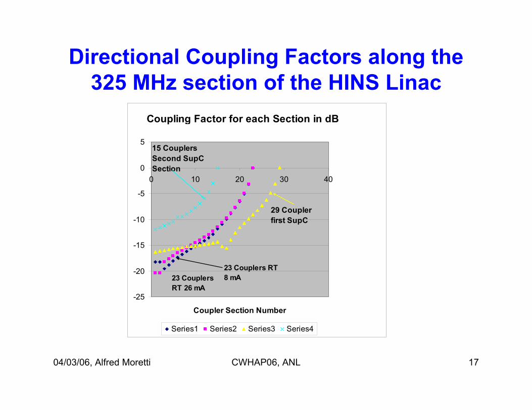
Directional Coupling Factors along the 325 MHz section of the HINS Linac
Coupling Factor for each Section in dB
-25
-20
-15
-10
-5
0
5
0 10 20 30 40
Coupler Section Number
Series1 Series2 Series3 Series4
29 Couplerfirst SupC
15 CouplersSecond SupCSection
23 Couplers RT 8 mA23 Couplers
RT 26 mA

04/03/06, Alfred Moretti CWHAP06, ANL 18
HINS 325 MHz Klystron
Toshiba E3740AFermi325 MHz 2.5 MW
Specifications:
Beam V= 98 kV
Beam I= 51 A
Perveance=1.75uP
Gain= 47 dB
Efficiency=50 %
Modulating Anode grounded to make a diode tube.

04/03/06, Alfred Moretti CWHAP06, ANL 19
325 MHzFront-EndLinac
325 MHz Klystron – Toshiba E3740A (JPARC)
115kV Pulse Transformer
ModulatorCapacitor / Switch / Bouncer
ChargingSupply
RFQ
MEBT
SCRF SpokeResonatorCryomodules
RFDistributionWaveguide
FerriteTuners
Single KlystronFeeds SCRF Linacto E > 100 MeV

04/03/06, Alfred Moretti CWHAP06, ANL 20
RF Fan-out for 8 GeV Linac
CIRCULATOR/ ISOLATOR
Magic Tee
FerriteLoaded Stub
CAVITYBEAM
1/8 Power Split (9.03 dB)
DIRECTIONAL COUPLER
1/7 Power Split (8.45 dB)
1/6 Power Split (7.78 dB)
1/5 Power Split (6.99 dB)
1/4 Power Split (6.02 dB)
1/3 Power Split (4.77 dB)
1/2 Power Split (3.01 dB)
E-H TUNER
KLYSTRON
35 footwaveguidefrom galleryto tunnel

04/03/06, Alfred Moretti CWHAP06, ANL 21
325 MHz kltsron in Meson Building on wheels.

04/03/06, Alfred Moretti CWHAP06, ANL 22
Bouncer Modulator
Specifications:• 9 kV at 1800 A• Pulses: 1.5 ms at 10 Hz
3.0 ms at 5 Hz4.5 ms at 2.5 Hz
• Regulation: 1 %• Droop : +/- 0.5 %

04/03/06, Alfred Moretti CWHAP06, ANL 23
Bouncer Modulator• Switch connects main
capacitor bank to transformer during pulse.
• Transformer steps up voltage to 120kV/130A (12:1)
• Main capacitor bank discharges by 20% during pulse
• “Bouncer” circuit compensates for cap bank droop.

04/03/06, Alfred Moretti CWHAP06, ANL 24

04/03/06, Alfred Moretti CWHAP06, ANL 25
System Control Forward/Reflected Power
Photo Detector Video Pulse
Klystron Protection Interlock Boards

04/03/06, Alfred Moretti CWHAP06, ANL 26
VME_P1 VME_P2 CAV VAC1, VAC2, VAC3 TEMP MOD
STATUSSYS CONTROL
MOD_EN RF_INHIBIT
VME_P1 VME_P2VIDEO PULSERF LEAKAGE
WG PRESSURE1WG PRESSURE2
VME_P1 VME_P2KLY FWR PWRKLY REFL PWRCIR FWR PWRCIR REFL PWR
VME_P1 VME_P2PMT KLY WINDOW
PMT COUPLERPMT CH3PMT CH4
VME_P1 VME_P2PHOTODET_CH1PHOTODET_CH2PHOTODET_CH3PHOTODET_CH4
VME_P1 VME_P2
MVME 2401UPROCESSOR
EPICS
VME_P1 VME_P2E_FIELD PROBE1E_FIELD_PROBE2E_FIELD_PROBE3
Ext INTLKS
MOD INTLKS
VME64X BACKPLANE
LLRF & AMP
KLYSTRON
FAST SWITCH
text DIR COUPLER CIRWAVEGUIDE WAVEGUIDE
text
C
DIR COUPLER
text
C
XFMR
HIGH INTENSITY PROTON SOURCE AND SMTF RF INTERLOCKS
text
CO
UPL
ER
PMT

04/03/06, Alfred Moretti CWHAP06, ANL 27
AFT 1.3 GHz IQM Specification
Coaxial Ferrite Stub tuners tested at ANL at 352 MHz;
1 5/8 inch line tested to 85 kW peak and o.4 % duty. 120 degree phase shift
3 1/8 inch line tested to 445 kW peak and o.4 % duty. 60 degree phase shift

04/03/06, Alfred Moretti CWHAP06, ANL 28
Conclusions
• The 805 MHz High Energy Femilab Injector Linac installed in the early 90 ‘s has accomplished its mission of increasing the space charge limit of injecting into the Booster. Early problems with storage life time of the klystrons have been over come.
• The 201 MHz section Low Energy section of the Linac being an old machine has problems with tube replacement if the only vendors go out of business. Faster feedback and feed-forwards circuit studies to improve the regulation of Phase and Amplitudedue to beam loading are underway.
• Most of the components for the 325 MHz HINS linac are on-hand.Testing of the klystron is scheduled for late June or early July of this year.