Embed Size (px)
Citation preview
1 © 2013 ANSYS, Inc. June 3, 2014 ANSYS Confidential © 2013 ANSYS, Inc. June 3, 2014 ANSYS Confidential
High Power Electronics Design
Zed (Zhangjun) Tang
ANSYS, Inc
June 3, 2014
2 © 2013 ANSYS, Inc. June 3, 2014 ANSYS Confidential © 2013 ANSYS, Inc. June 3, 2014 ANSYS Confidential
• Part I: EMI/EMC • Part II: Multiphysics – Thermal/Structural
Outline
3 © 2013 ANSYS, Inc. June 3, 2014 ANSYS Confidential © 2013 ANSYS, Inc. June 3, 2014 ANSYS Confidential
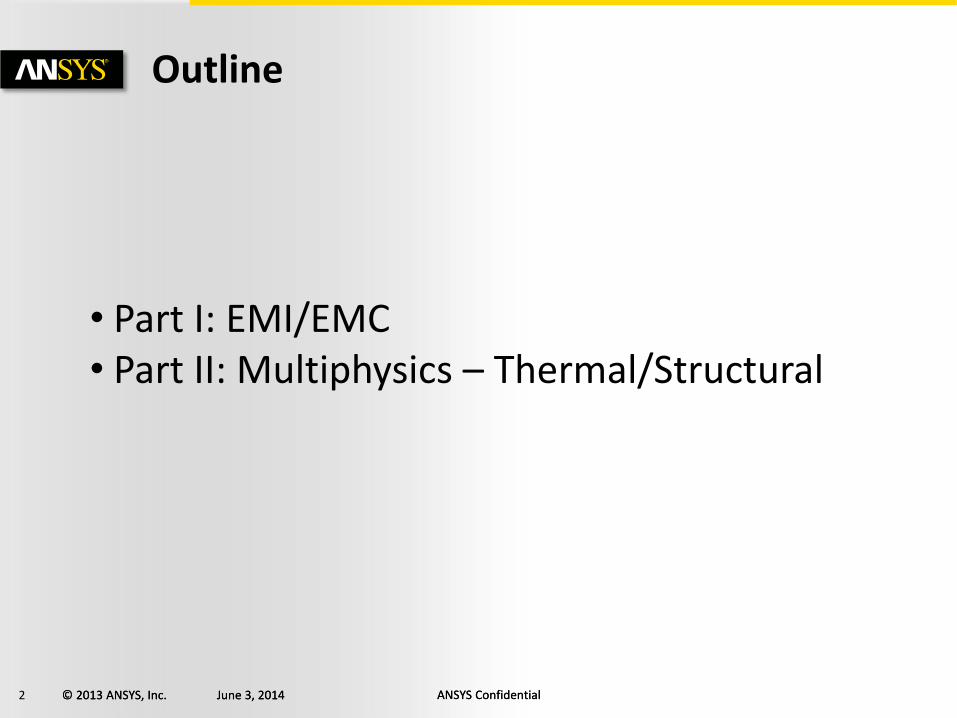
• EMI/EMC
– Magnetic Field
– Electric Field
– Conducted Fields
– Radiated Fields
– Testing and solutions
– Simulation is solving EMI/EMC problems both quantitatively and qualitatively
“Electronics is outpacing the basic construction of these boards . . . we’re going to have to change how we do things.” - Paul Huray, Ph.D.
Professor of Electrical Engineering, University of South Carolina
Part I: EMI/EMC
4 © 2013 ANSYS, Inc. June 3, 2014 ANSYS Confidential © 2013 ANSYS, Inc. June 3, 2014 ANSYS Confidential
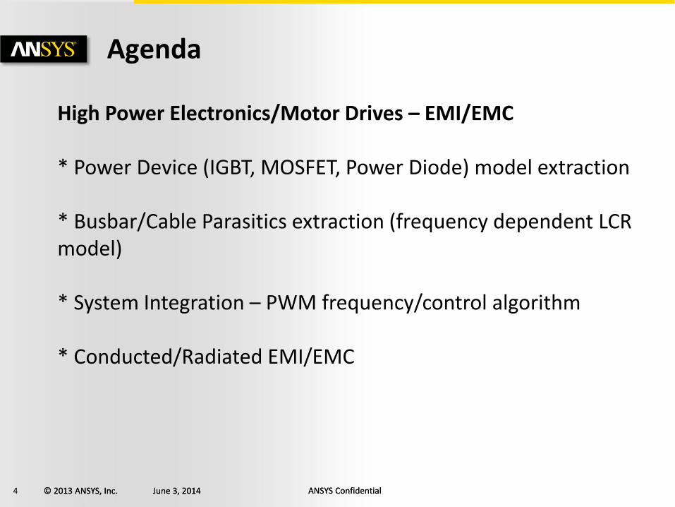
Agenda
High Power Electronics/Motor Drives – EMI/EMC * Power Device (IGBT, MOSFET, Power Diode) model extraction * Busbar/Cable Parasitics extraction (frequency dependent LCR model) * System Integration – PWM frequency/control algorithm * Conducted/Radiated EMI/EMC
5 © 2013 ANSYS, Inc. June 3, 2014 ANSYS Confidential © 2013 ANSYS, Inc. June 3, 2014 ANSYS Confidential
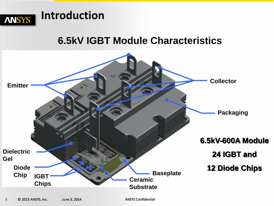
Introduction
6.5kV IGBT Module Characteristics
Baseplate
Collector Emitter
IGBT
Chips
Diode
Chip
6.5kV-600A Module
24 IGBT and
12 Diode Chips
Dielectric
Gel
Packaging
Ceramic
Substrate
6 © 2013 ANSYS, Inc. June 3, 2014 ANSYS Confidential © 2013 ANSYS, Inc. June 3, 2014 ANSYS Confidential
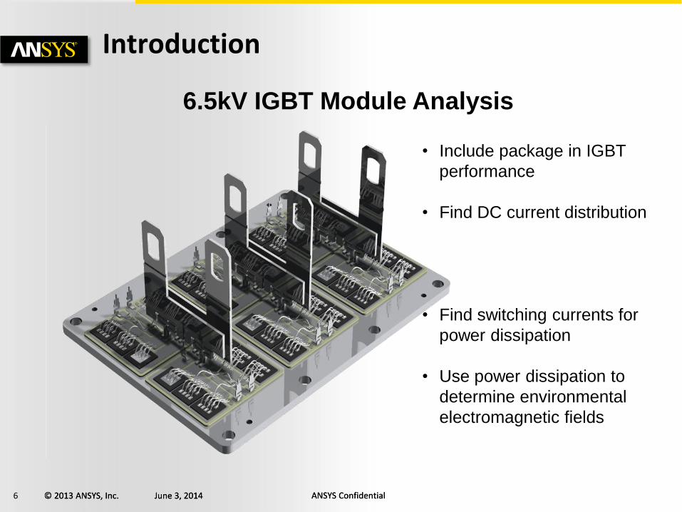
Introduction
6.5kV IGBT Module Analysis
• Include package in IGBT
performance
• Find DC current distribution
• Find switching currents for
power dissipation
• Use power dissipation to
determine environmental
electromagnetic fields
7 © 2013 ANSYS, Inc. June 3, 2014 ANSYS Confidential © 2013 ANSYS, Inc. June 3, 2014 ANSYS Confidential
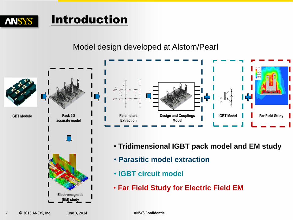
Model design developed at Alstom/Pearl
IGBT Module Pack 3D
accurate model
Parameters
Extraction
Electromagnetic
(EM) study
Design and Couplings
Model IGBT Model
• Tridimensional IGBT pack model and EM study
• Parasitic model extraction
• IGBT circuit model
Far Field Study
• Far Field Study for Electric Field EM
Introduction
8 © 2013 ANSYS, Inc. June 3, 2014 ANSYS Confidential © 2013 ANSYS, Inc. June 3, 2014 ANSYS Confidential
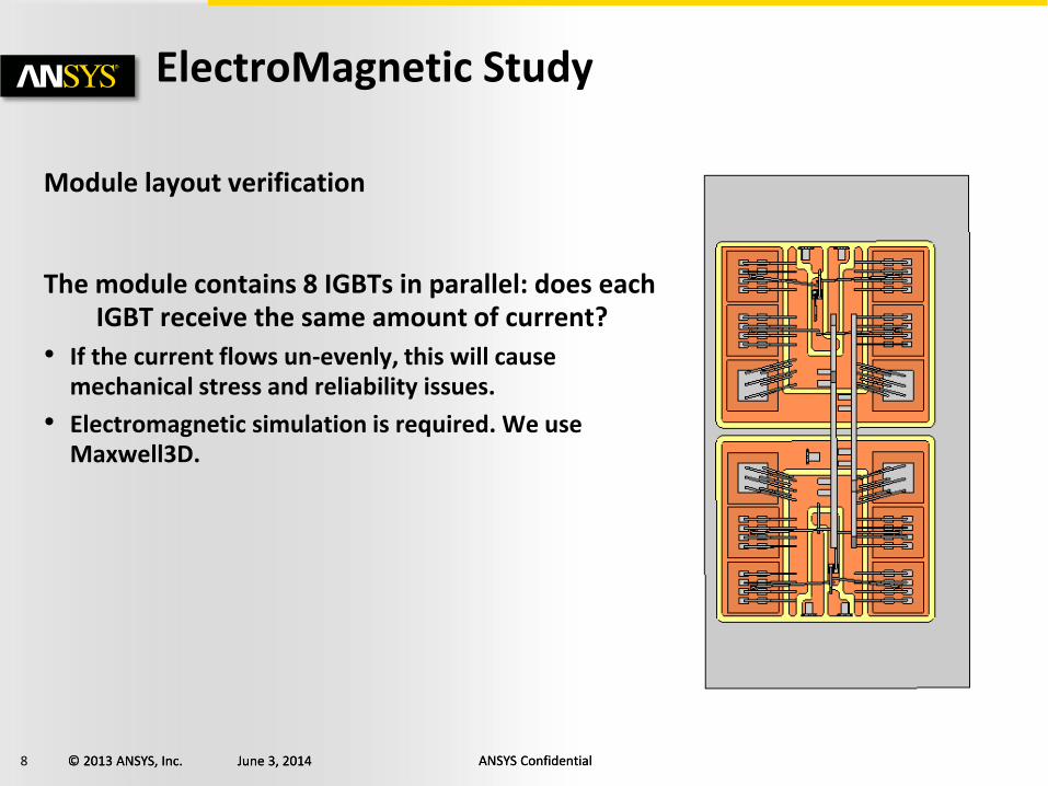
ElectroMagnetic Study
Module layout verification
The module contains 8 IGBTs in parallel: does each IGBT receive the same amount of current?
• If the current flows un-evenly, this will cause mechanical stress and reliability issues.
• Electromagnetic simulation is required. We use Maxwell3D.

9 © 2013 ANSYS, Inc. June 3, 2014 ANSYS Confidential © 2013 ANSYS, Inc. June 3, 2014 ANSYS Confidential
ElectroMagnetic Study
The layout in imported from the CAD tool
The DC solver is used
The input current (600 A) is defined
The sink (return current path) is defined
Outputs: conduction path and current distribution
600 A Sink
10 © 2013 ANSYS, Inc. June 3, 2014 ANSYS Confidential © 2013 ANSYS, Inc. June 3, 2014 ANSYS Confidential
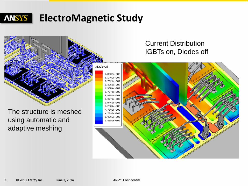
ElectroMagnetic Study
The structure is meshed
using automatic and
adaptive meshing
Current Distribution
IGBTs on, Diodes off
11 © 2013 ANSYS, Inc. June 3, 2014 ANSYS Confidential © 2013 ANSYS, Inc. June 3, 2014 ANSYS Confidential
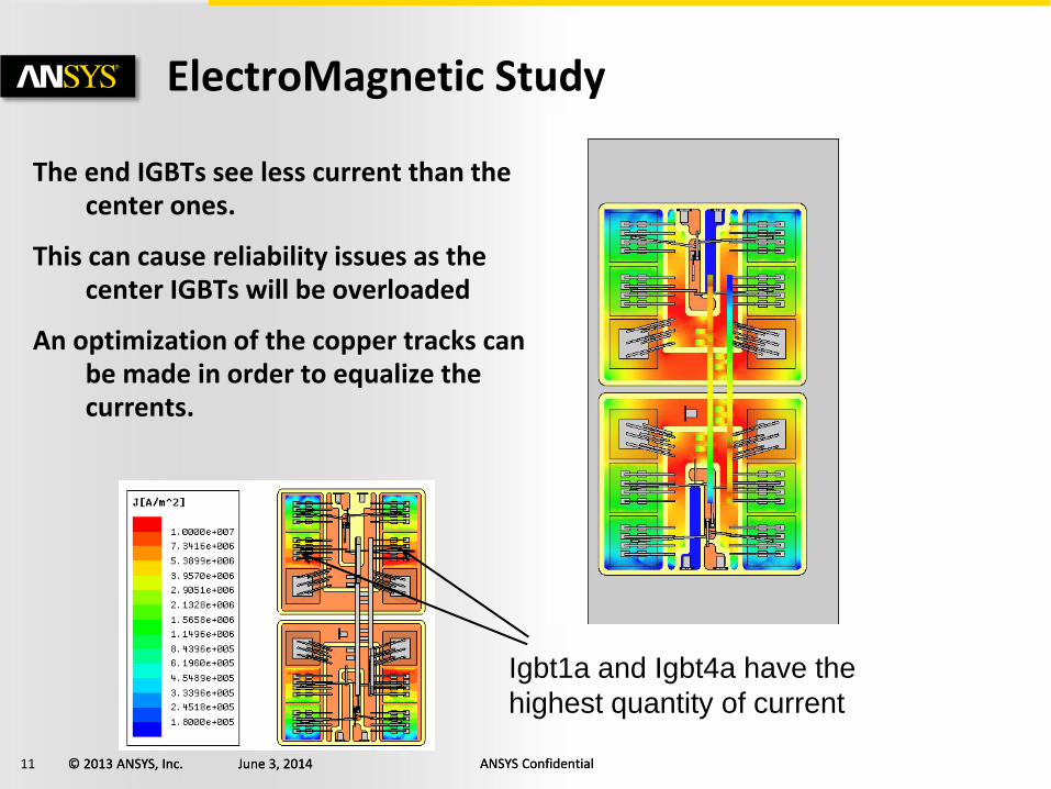
ElectroMagnetic Study
The end IGBTs see less current than the center ones.
This can cause reliability issues as the center IGBTs will be overloaded
An optimization of the copper tracks can be made in order to equalize the currents.
Igbt1a and Igbt4a have the
highest quantity of current
12 © 2013 ANSYS, Inc. June 3, 2014 ANSYS Confidential © 2013 ANSYS, Inc. June 3, 2014 ANSYS Confidential
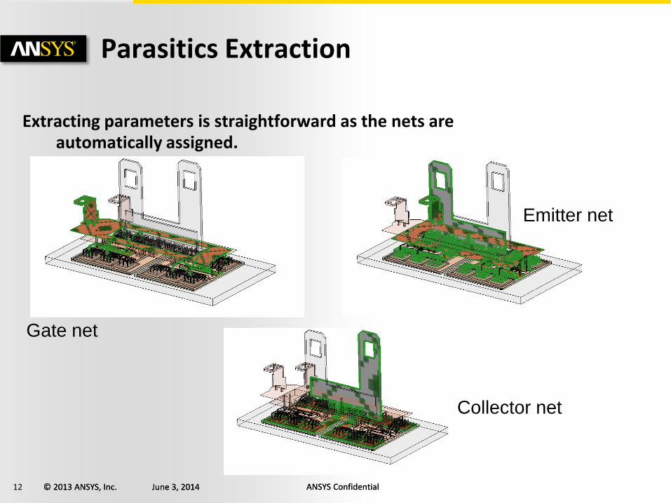
Extracting parameters is straightforward as the nets are automatically assigned.
Parasitics Extraction
Gate net
Emitter net
Collector net
13 © 2013 ANSYS, Inc. June 3, 2014 ANSYS Confidential © 2013 ANSYS, Inc. June 3, 2014 ANSYS Confidential
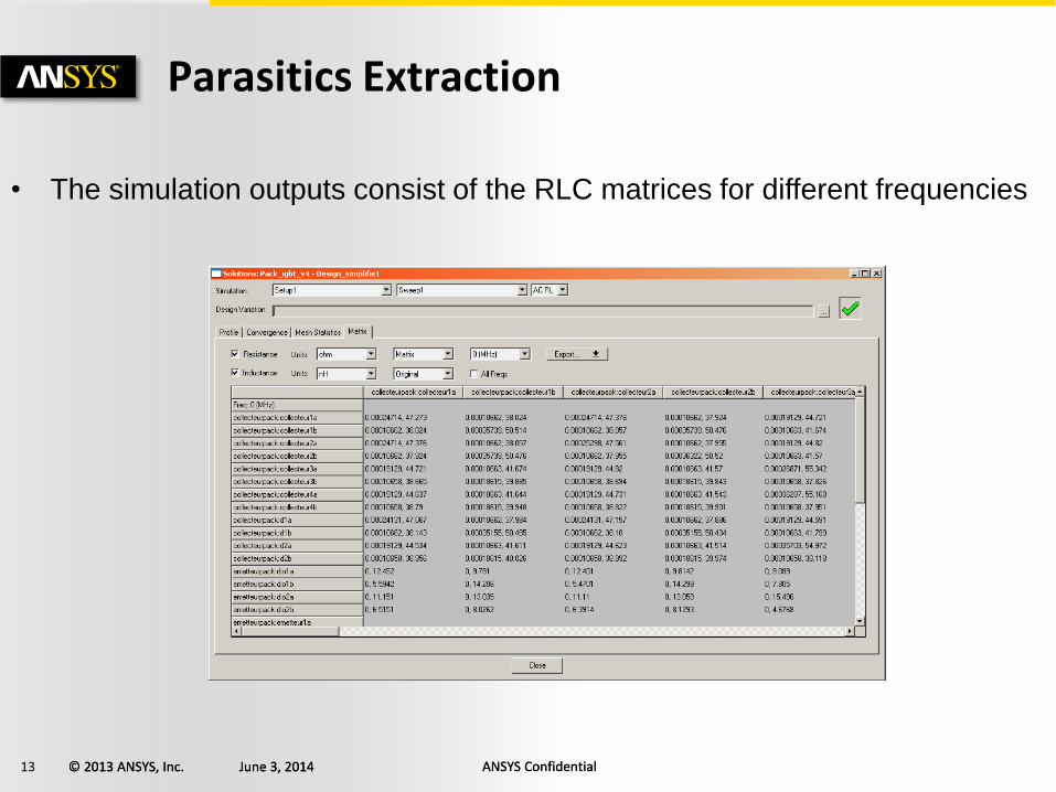
Parasitics Extraction
• The simulation outputs consist of the RLC matrices for different frequencies
14 © 2013 ANSYS, Inc. June 3, 2014 ANSYS Confidential © 2013 ANSYS, Inc. June 3, 2014 ANSYS Confidential
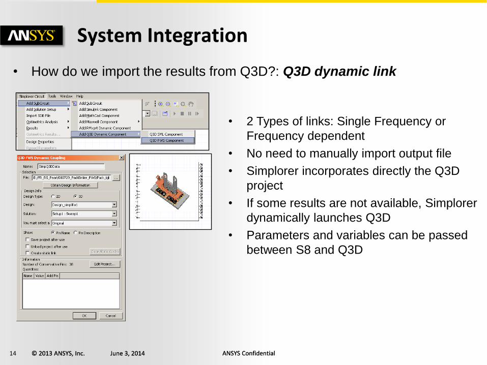
System Integration
• How do we import the results from Q3D?: Q3D dynamic link
• 2 Types of links: Single Frequency or
Frequency dependent
• No need to manually import output file
• Simplorer incorporates directly the Q3D
project
• If some results are not available, Simplorer
dynamically launches Q3D
• Parameters and variables can be passed
between S8 and Q3D
15 © 2013 ANSYS, Inc. June 3, 2014 ANSYS Confidential © 2013 ANSYS, Inc. June 3, 2014 ANSYS Confidential
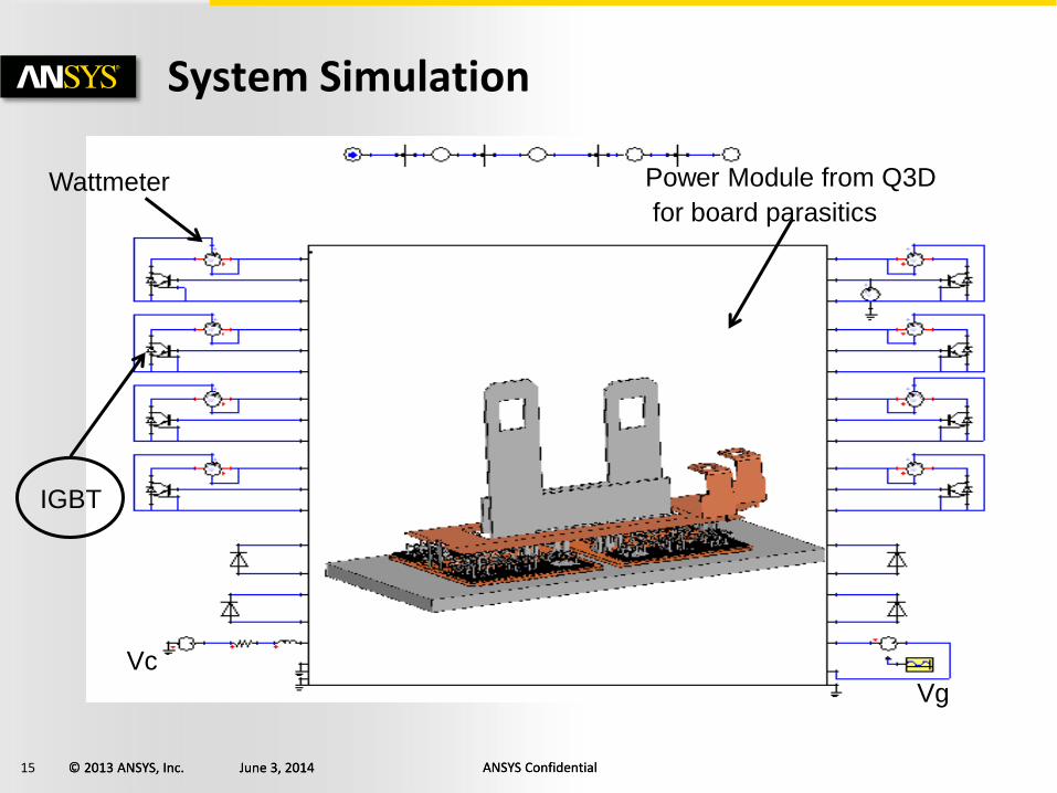
System Simulation
IGBT
Wattmeter
Vc
Vg
Power Module from Q3D
for board parasitics
16 © 2013 ANSYS, Inc. June 3, 2014 ANSYS Confidential © 2013 ANSYS, Inc. June 3, 2014 ANSYS Confidential
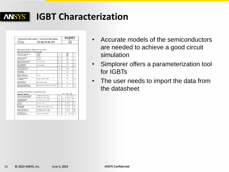
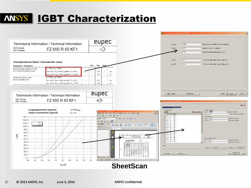
IGBT Characterization
• Accurate models of the semiconductors
are needed to achieve a good circuit
simulation
• Simplorer offers a parameterization tool
for IGBTs
• The user needs to import the data from
the datasheet
17 © 2013 ANSYS, Inc. June 3, 2014 ANSYS Confidential © 2013 ANSYS, Inc. June 3, 2014 ANSYS Confidential
SheetScan
IGBT Characterization
18 © 2013 ANSYS, Inc. June 3, 2014 ANSYS Confidential © 2013 ANSYS, Inc. June 3, 2014 ANSYS Confidential
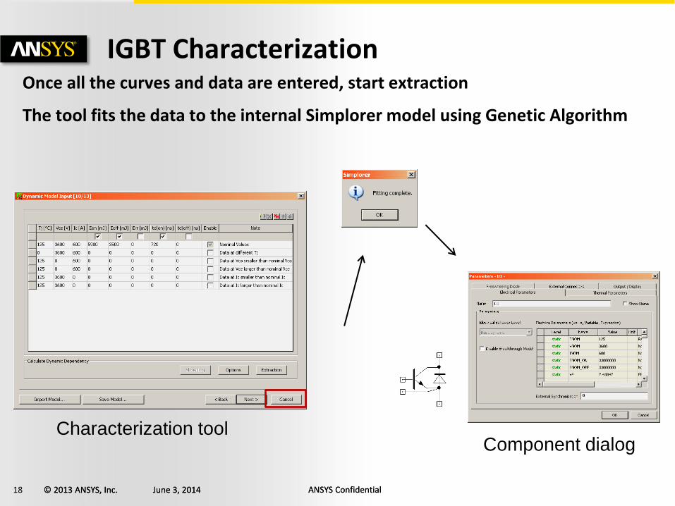
Once all the curves and data are entered, start extraction
The tool fits the data to the internal Simplorer model using Genetic Algorithm
IGBT Characterization
Characterization tool
Component dialog
19 © 2013 ANSYS, Inc. June 3, 2014 ANSYS Confidential © 2013 ANSYS, Inc. June 3, 2014 ANSYS Confidential
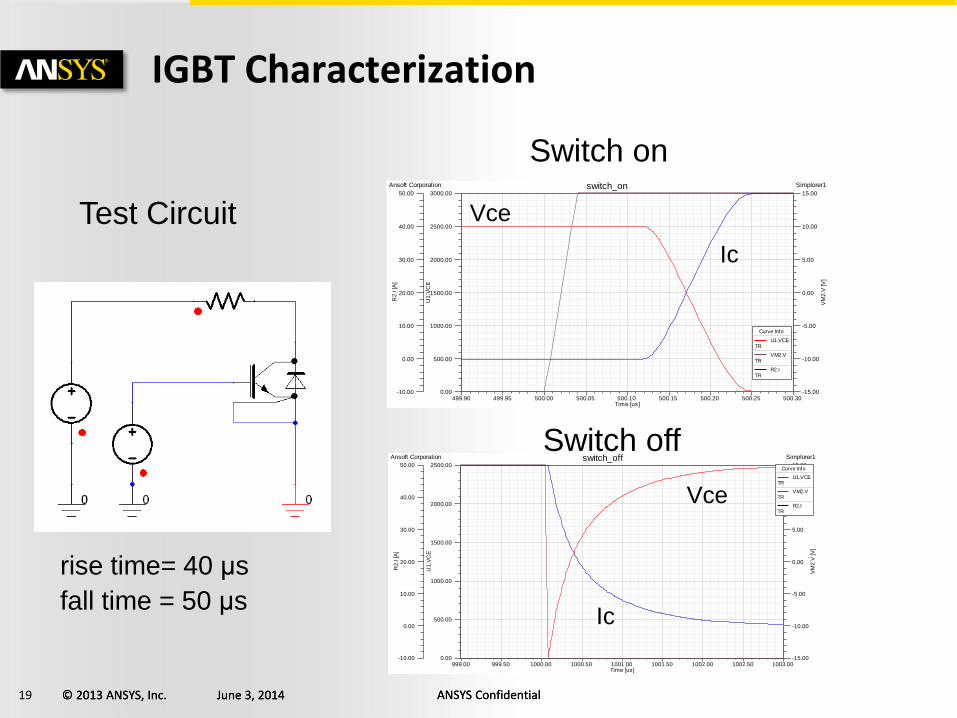
IGBT Characterization
Test Circuit
499.90 499.95 500.00 500.05 500.10 500.15 500.20 500.25 500.30Time [us]
0.00
500.00
1000.00
1500.00
2000.00
2500.00
3000.00
U1
.VC
E
-15.00
-10.00
-5.00
0.00
5.00
10.00
15.00
VM
2.V
[V
]
-10.00
0.00
10.00
20.00
30.00
40.00
50.00
R2
.I [A
]
Ansoft Corporation Simplorer1switch_on
Curve Info
U1.VCETR
VM2.VTR
R2.ITR
999.00 999.50 1000.00 1000.50 1001.00 1001.50 1002.00 1002.50 1003.00Time [us]
0.00
500.00
1000.00
1500.00
2000.00
2500.00
U1
.VC
E
-15.00
-10.00
-5.00
0.00
5.00
10.00
15.00
VM
2.V
[V
]
-10.00
0.00
10.00
20.00
30.00
40.00
50.00
R2
.I [A
]
Ansoft Corporation Simplorer1switch_offCurve Info
U1.VCETR
VM2.VTR
R2.ITR
Switch on
Switch off
Vce
Vce
Ic
Ic
rise time= 40 μs
fall time = 50 μs
20 © 2013 ANSYS, Inc. June 3, 2014 ANSYS Confidential © 2013 ANSYS, Inc. June 3, 2014 ANSYS Confidential
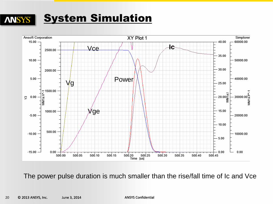
Vce
Vg
Vge
Ic
Power
The power pulse duration is much smaller than the rise/fall time of Ic and Vce
System Simulation
21 © 2013 ANSYS, Inc. June 3, 2014 ANSYS Confidential © 2013 ANSYS, Inc. June 3, 2014 ANSYS Confidential
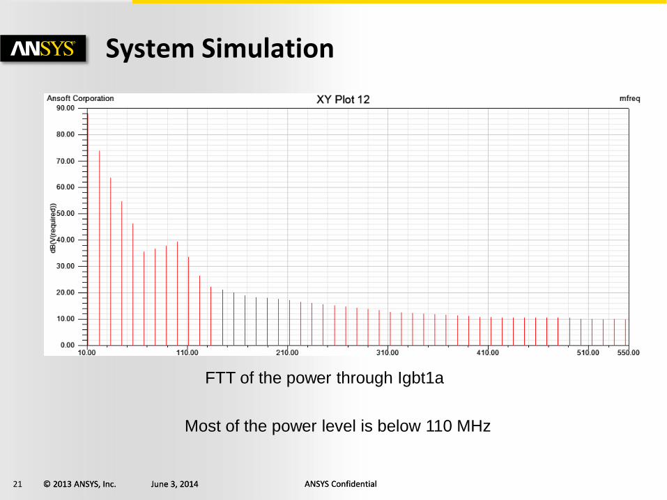
System Simulation
FTT of the power through Igbt1a
Most of the power level is below 110 MHz
22 © 2013 ANSYS, Inc. June 3, 2014 ANSYS Confidential © 2013 ANSYS, Inc. June 3, 2014 ANSYS Confidential
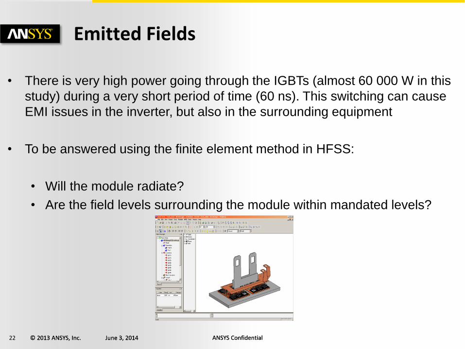
Emitted Fields
• There is very high power going through the IGBTs (almost 60 000 W in this
study) during a very short period of time (60 ns). This switching can cause
EMI issues in the inverter, but also in the surrounding equipment
• To be answered using the finite element method in HFSS:
• Will the module radiate?
• Are the field levels surrounding the module within mandated levels?
23 © 2013 ANSYS, Inc. June 3, 2014 ANSYS Confidential © 2013 ANSYS, Inc. June 3, 2014 ANSYS Confidential
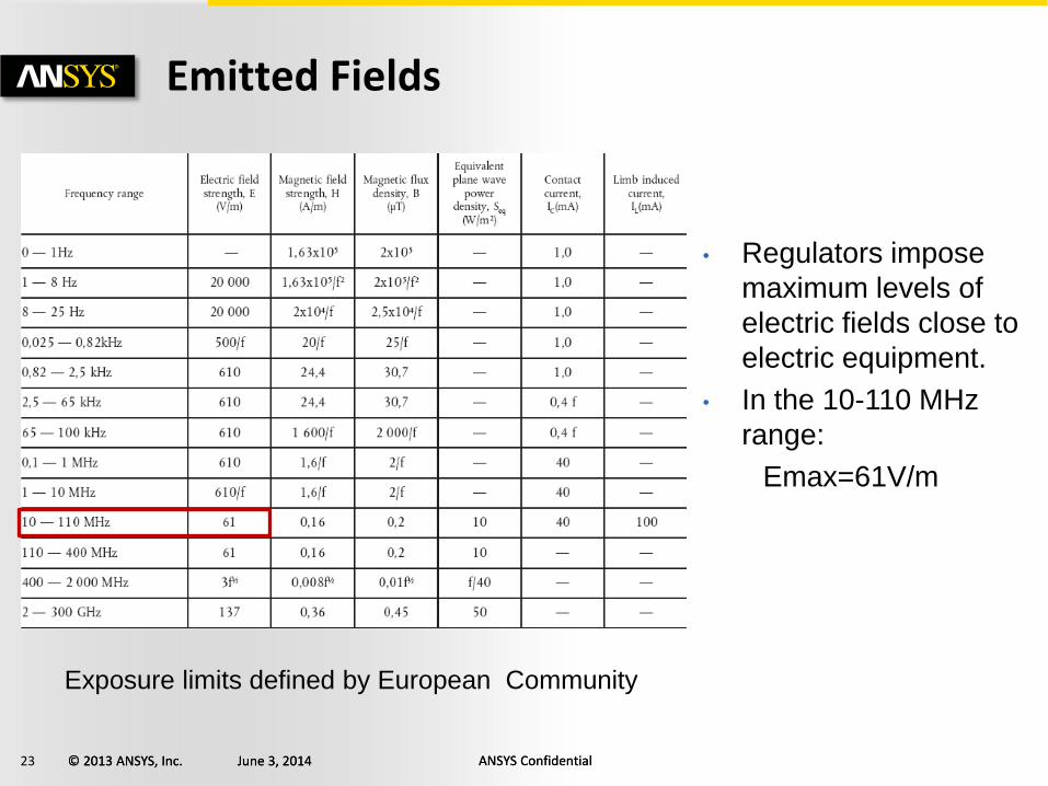
Emitted Fields
• Regulators impose
maximum levels of
electric fields close to
electric equipment.
• In the 10-110 MHz
range:
Emax=61V/m
Exposure limits defined by European Community
24 © 2013 ANSYS, Inc. June 3, 2014 ANSYS Confidential © 2013 ANSYS, Inc. June 3, 2014 ANSYS Confidential
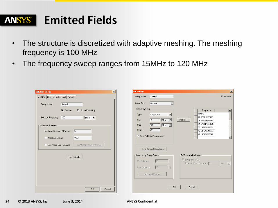
Emitted Fields
• The structure is discretized with adaptive meshing. The meshing
frequency is 100 MHz
• The frequency sweep ranges from 15MHz to 120 MHz
25 © 2013 ANSYS, Inc. June 3, 2014 ANSYS Confidential © 2013 ANSYS, Inc. June 3, 2014 ANSYS Confidential
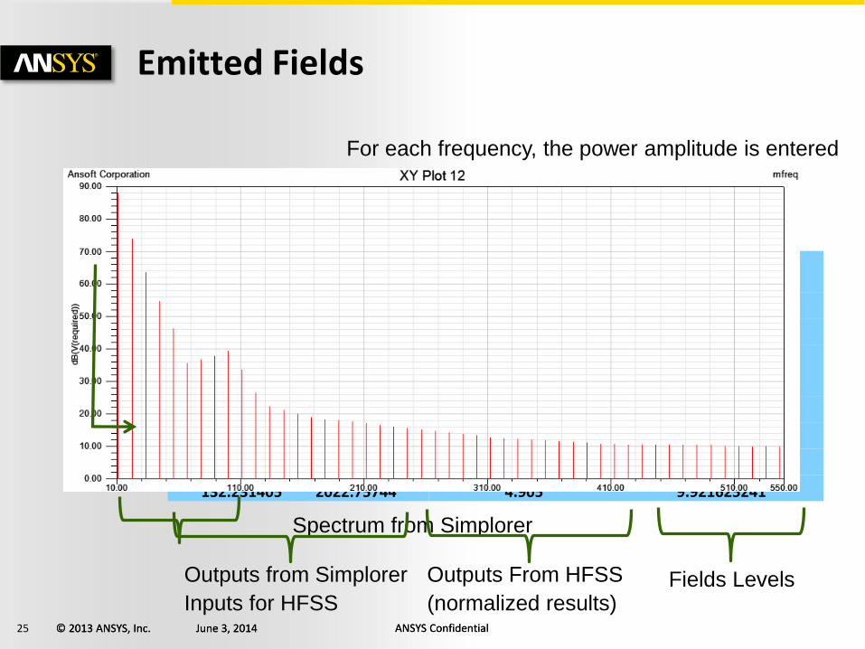
Emitted Fields
For each frequency, the power amplitude is entered
Spectrum (MHz) Power
(W) E field at 1m for 1000w
(V/m) E field at 1m
(V/m)
16.52892562 21439.97604 2.6312 56.41286497
33.05785124 8635.09049 2.7994 24.17307232
49.58677686 5579.619715 2.8731 16.0308054
66.11570248 4131.16773 3.063 12.65376676
82.6446281 3276.823585 3.4045 11.15594589
99.17355372 2712.888158 3.8924 10.55964586
115.7024793 2308.359536 4.4861 10.35553171
132.231405 2022.75744 4.905 9.921625241
Spectrum from Simplorer
Outputs from Simplorer
Inputs for HFSS
Outputs From HFSS
(normalized results) Fields Levels

26 © 2013 ANSYS, Inc. June 3, 2014 ANSYS Confidential © 2013 ANSYS, Inc. June 3, 2014 ANSYS Confidential
Emitted Fields
• The E field is very localized
close to the module even at
100 MHz
• However, the very high
power can lead to large
values of E field even far
from the module
• This design is fine at
110MHz.
mag E @ 100 MHz, Power = 10 000W
Spectrum (MHz)Power
(W)E field at 1m for 1000w
(V/m)E field at 1m
(V/m)
16.52892562 21439.97604 2.6312 56.41286497
33.05785124 8635.09049 2.7994 24.17307232
49.58677686 5579.619715 2.8731 16.0308054
66.11570248 4131.16773 3.063 12.65376676
82.6446281 3276.823585 3.4045 11.15594589
99.17355372 2712.888158 3.8924 10.55964586
115.7024793 2308.359536 4.4861 10.35553171
132.231405 2022.75744 4.905 9.921625241
27 © 2013 ANSYS, Inc. June 3, 2014 ANSYS Confidential © 2013 ANSYS, Inc. June 3, 2014 ANSYS Confidential
Context / Introduction
Component level Modeling
System level Modeling – Electrical Domain
Multiphysics Modeling - Workbench
Conclusions
Part II: Multiphysics -- Outline
28 © 2013 ANSYS, Inc. June 3, 2014 ANSYS Confidential © 2013 ANSYS, Inc. June 3, 2014 ANSYS Confidential
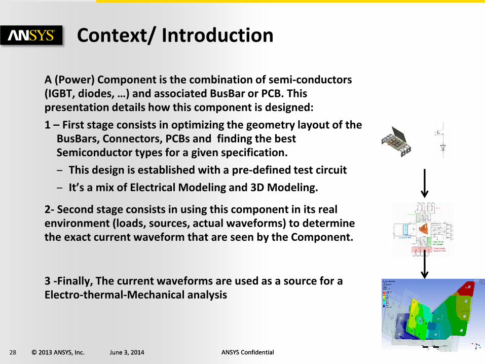
A (Power) Component is the combination of semi-conductors (IGBT, diodes, …) and associated BusBar or PCB. This presentation details how this component is designed:
1 – First stage consists in optimizing the geometry layout of the BusBars, Connectors, PCBs and finding the best Semiconductor types for a given specification.
– This design is established with a pre-defined test circuit
– It’s a mix of Electrical Modeling and 3D Modeling.
2- Second stage consists in using this component in its real environment (loads, sources, actual waveforms) to determine the exact current waveform that are seen by the Component.
3 -Finally, The current waveforms are used as a source for a Electro-thermal-Mechanical analysis
Context/ Introduction
29 © 2013 ANSYS, Inc. June 3, 2014 ANSYS Confidential © 2013 ANSYS, Inc. June 3, 2014 ANSYS Confidential
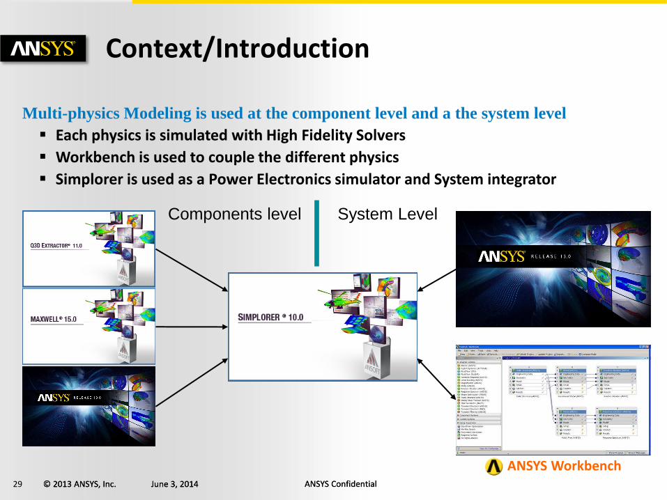
Context/Introduction
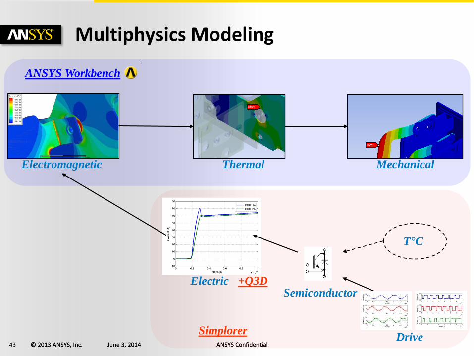
Multi-physics Modeling is used at the component level and a the system level
Each physics is simulated with High Fidelity Solvers
Workbench is used to couple the different physics
Simplorer is used as a Power Electronics simulator and System integrator
Components level System Level
Simplorer
ANSYS Workbench
30 © 2013 ANSYS, Inc. June 3, 2014 ANSYS Confidential © 2013 ANSYS, Inc. June 3, 2014 ANSYS Confidential
Component Level Modeling
31 © 2013 ANSYS, Inc. June 3, 2014 ANSYS Confidential © 2013 ANSYS, Inc. June 3, 2014 ANSYS Confidential
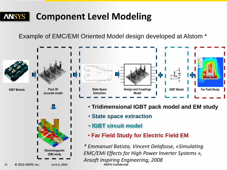
Component Level Modeling
Example of EMC/EMI Oriented Model design developed at Alstom *
IGBT Module Pack 3D
accurate model
State Space
Extraction
Electromagnetic
(EM) study
Design and Couplings
Model IGBT Model
• Tridimensional IGBT pack model and EM study
• State space extraction
• IGBT circuit model
Far Field Study
• Far Field Study for Electric Field EM
* Emmanuel Batista, Vincent Delafosse, «Simulating EMC/EMI Effects for High Power Inverter Systems », Ansoft Inspiring Engineering, 2008
32 © 2013 ANSYS, Inc. June 3, 2014 ANSYS Confidential © 2013 ANSYS, Inc. June 3, 2014 ANSYS Confidential
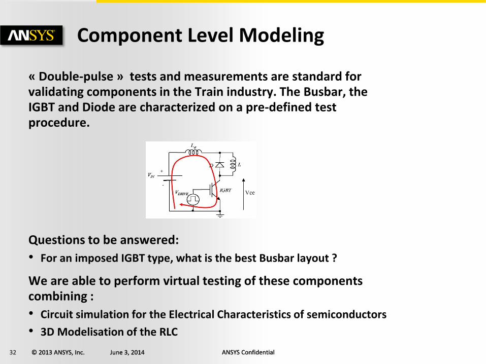
« Double-pulse » tests and measurements are standard for validating components in the Train industry. The Busbar, the IGBT and Diode are characterized on a pre-defined test procedure.
Questions to be answered:
• For an imposed IGBT type, what is the best Busbar layout ?
We are able to perform virtual testing of these components combining :
• Circuit simulation for the Electrical Characteristics of semiconductors
• 3D Modelisation of the RLC
Component Level Modeling
33 © 2013 ANSYS, Inc. June 3, 2014 ANSYS Confidential © 2013 ANSYS, Inc. June 3, 2014 ANSYS Confidential
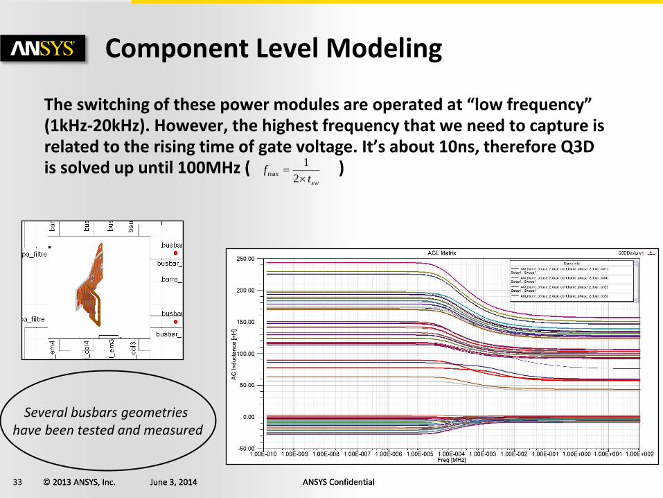
The switching of these power modules are operated at “low frequency” (1kHz-20kHz). However, the highest frequency that we need to capture is related to the rising time of gate voltage. It’s about 10ns, therefore Q3D is solved up until 100MHz ( )
Component Level Modeling
swtf
2
1max
Several busbars geometries
have been tested and measured
34 © 2013 ANSYS, Inc. June 3, 2014 ANSYS Confidential © 2013 ANSYS, Inc. June 3, 2014 ANSYS Confidential
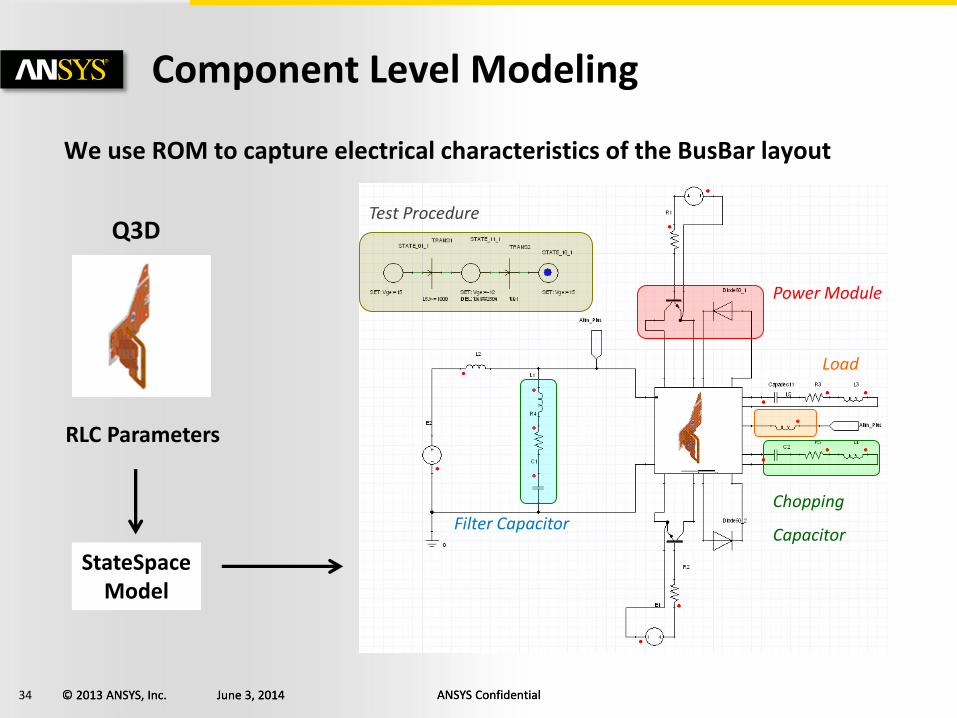
Q3D
Component Level Modeling
Chopping
Capacitor Filter Capacitor
Power Module
Load
Test Procedure
RLC Parameters
StateSpace Model
We use ROM to capture electrical characteristics of the BusBar layout
35 © 2013 ANSYS, Inc. June 3, 2014 ANSYS Confidential © 2013 ANSYS, Inc. June 3, 2014 ANSYS Confidential
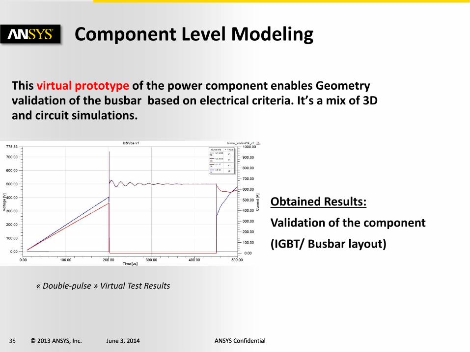
This virtual prototype of the power component enables Geometry validation of the busbar based on electrical criteria. It’s a mix of 3D and circuit simulations.
Component Level Modeling
Obtained Results:
Validation of the component
(IGBT/ Busbar layout)
« Double-pulse » Virtual Test Results
36 © 2013 ANSYS, Inc. June 3, 2014 ANSYS Confidential © 2013 ANSYS, Inc. June 3, 2014 ANSYS Confidential
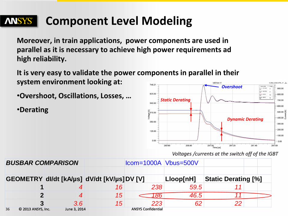
Moreover, in train applications, power components are used in parallel as it is necessary to achieve high power requirements ad high reliability.
It is very easy to validate the power components in parallel in their system environment looking at:
•Overshoot, Oscillations, Losses, …
•Derating
Component Level Modeling
Voltages /currents at the switch off of the IGBT
Static Derating
Dynamic Derating
Overshoot
BUSBAR COMPARISON Icom=1000A Vbus=500V
GEOMETRY dI/dt [kA/µs] dV/dt [kV/µs]DV [V] Lloop[nH] Static Derating [%]
1 4 16 238 59.5 11
2 4 15 186 46.5 11
3 3.6 15 223 62 22
37 © 2013 ANSYS, Inc. June 3, 2014 ANSYS Confidential © 2013 ANSYS, Inc. June 3, 2014 ANSYS Confidential
System level Modeling – Electrical Domain
38 © 2013 ANSYS, Inc. June 3, 2014 ANSYS Confidential © 2013 ANSYS, Inc. June 3, 2014 ANSYS Confidential
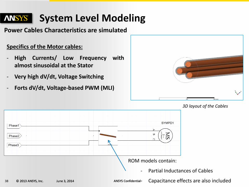
System Level Modeling
Power Cables Characteristics are simulated
Specifics of the Motor cables:
- High Currents/ Low Frequency with almost sinusoidal at the Stator
- Very high dV/dt, Voltage Switching
- Forts dV/dt, Voltage-based PWM (MLI)
3D layout of the Cables
ROM models contain:
- Partial Inductances of Cables
- Capacitance effects are also included
39 © 2013 ANSYS, Inc. June 3, 2014 ANSYS Confidential © 2013 ANSYS, Inc. June 3, 2014 ANSYS Confidential
System Level Modeling
Capacité de découplage
Capacité filtre
Composants de puissance
Charge
Ordre de pilotage
Chopping Capacitor
Filter Capacitor
Power Components
LOAD
Driving Logic
ROM Models of Busbar and Cables
40 © 2013 ANSYS, Inc. June 3, 2014 ANSYS Confidential © 2013 ANSYS, Inc. June 3, 2014 ANSYS Confidential
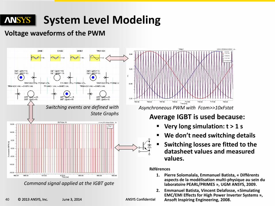
System Level Modeling Voltage waveforms of the PWM
Average IGBT is used because: Very long simulation: t > 1 s
We don’t need switching details
Switching losses are fitted to the datasheet values and measured values.
Références
1. Pierre Solomalala, Emmanuel Batista, « Différents aspects de la modélisation multi-physique au sein du laboratoire PEARL/PRIMES », UGM ANSYS, 2009.
2. Emmanuel Batista, Vincent Delafosse, «Simulating EMC/EMI Effects for High Power Inverter Systems », Ansoft Inspiring Engineering, 2008.
Asynchroneous PWM with Fcom>>10xFstat
Command signal applied at the IGBT gate
Switching events are defined with State Graphs
41 © 2013 ANSYS, Inc. June 3, 2014 ANSYS Confidential © 2013 ANSYS, Inc. June 3, 2014 ANSYS Confidential
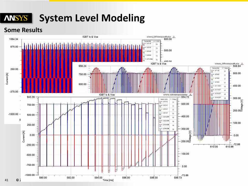
System Level Modeling
Some Results
42 © 2013 ANSYS, Inc. June 3, 2014 ANSYS Confidential © 2013 ANSYS, Inc. June 3, 2014 ANSYS Confidential
Multiphysics Modeling in Workbench
43 © 2013 ANSYS, Inc. June 3, 2014 ANSYS Confidential © 2013 ANSYS, Inc. June 3, 2014 ANSYS Confidential
Multiphysics Modeling
Electric
Thermal Electromagnetic Mechanical
Semiconductor
Drive
T°C
Simplorer
ANSYS Workbench
+Q3D
44 © 2013 ANSYS, Inc. June 3, 2014 ANSYS Confidential © 2013 ANSYS, Inc. June 3, 2014 ANSYS Confidential
Multiphysics Modeling
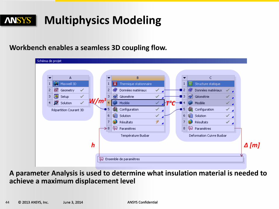
Workbench enables a seamless 3D coupling flow.
A parameter Analysis is used to determine what insulation material is needed to achieve a maximum displacement level
W/m3 T°C
Δ [m] h
45 © 2013 ANSYS, Inc. June 3, 2014 ANSYS Confidential © 2013 ANSYS, Inc. June 3, 2014 ANSYS Confidential
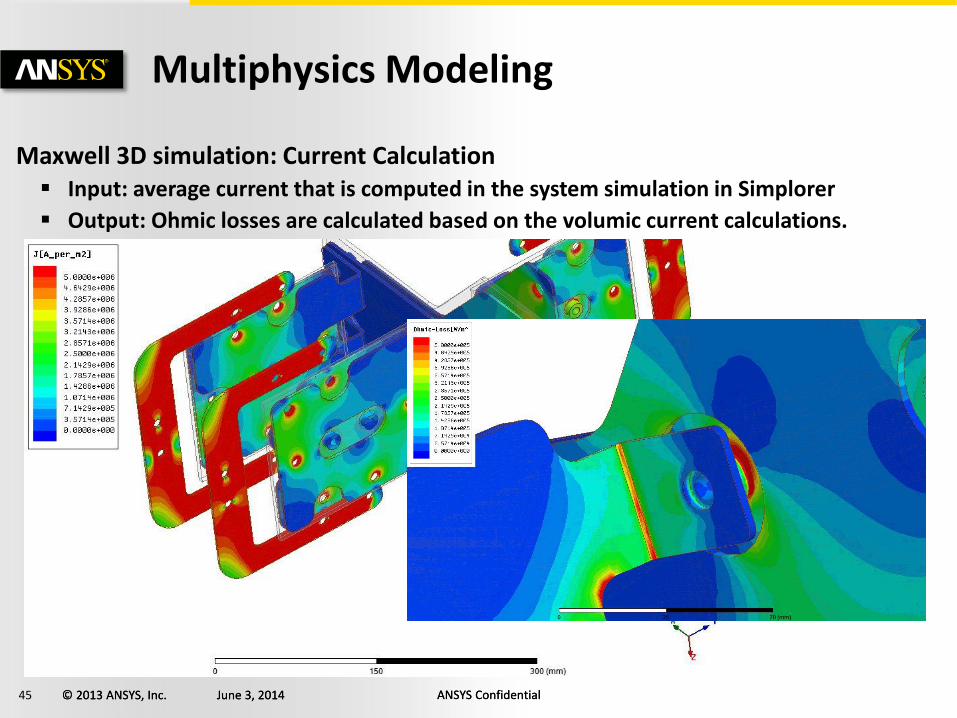
Multiphysics Modeling
Maxwell 3D simulation: Current Calculation Input: average current that is computed in the system simulation in Simplorer
Output: Ohmic losses are calculated based on the volumic current calculations.
46 © 2013 ANSYS, Inc. June 3, 2014 ANSYS Confidential © 2013 ANSYS, Inc. June 3, 2014 ANSYS Confidential
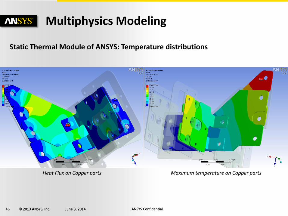
Multiphysics Modeling
Static Thermal Module of ANSYS: Temperature distributions
Heat Flux on Copper parts Maximum temperature on Copper parts
47 © 2013 ANSYS, Inc. June 3, 2014 ANSYS Confidential © 2013 ANSYS, Inc. June 3, 2014 ANSYS Confidential
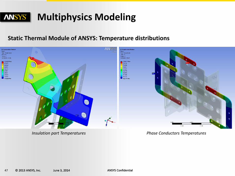
Multiphysics Modeling
Static Thermal Module of ANSYS: Temperature distributions
Insulation part Temperatures Phase Conductors Temperatures
48 © 2013 ANSYS, Inc. June 3, 2014 ANSYS Confidential © 2013 ANSYS, Inc. June 3, 2014 ANSYS Confidential
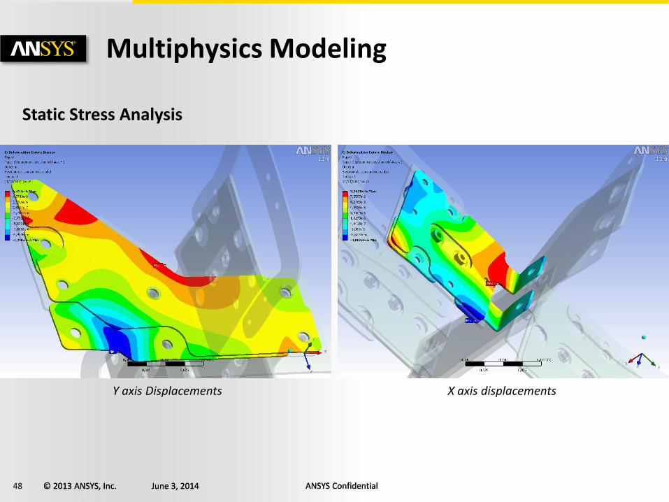
Multiphysics Modeling
Static Stress Analysis
Y axis Displacements X axis displacements
49 © 2013 ANSYS, Inc. June 3, 2014 ANSYS Confidential © 2013 ANSYS, Inc. June 3, 2014 ANSYS Confidential
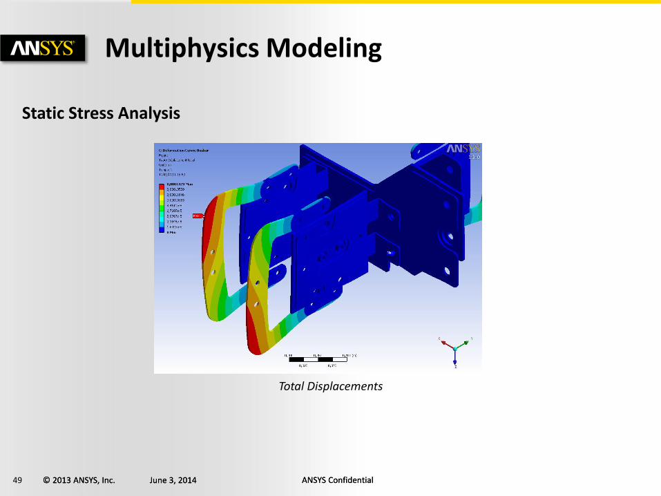
Multiphysics Modeling
Static Stress Analysis
Total Displacements
50 © 2013 ANSYS, Inc. June 3, 2014 ANSYS Confidential © 2013 ANSYS, Inc. June 3, 2014 ANSYS Confidential
Conclusion
A Multi-physics Multi level modelisation method has been presented
Dynamic IGBTS have been used at the component level
Average IGBT have been used at the system level
State Graphs enable easy development of the command algorithm used to drive each inverter
The Stress values are accurate as we have loaded the structure with real waveforms from system analysis.

51 © 2013 ANSYS, Inc. June 3, 2014 ANSYS Confidential