Embed Size (px)
Citation preview
High-power diode pumped Nd:YAG master oscillator power amplifier system
Alexander Gaydardzhiev1, Anton Trifonov2, Torsten Fiebig2, Ivan Buchvarov1
1Sofia University, Faculty of Physics, Department of Quantum Electronics, 5 James Bourchier
Blvd., BG-1164 Sofia, Bulgaria 2Department of Chemistry, Boston College, Eugene F. Merkert Chemistry Center, 2609
Beacon Street, Chestnut Hill, MA 02467, USA
ABSTRACT A nanosecond Nd:YAG based high-energy kilohertz Master Oscillator Power Amplifier (MOPA) system has been developed. The Q-switched master oscillator emits 6.5-ns, 1-kHz pulses with energy up to 1.6 mJ. The design of the oscillator ensures TEM00 operation with high stability and insensitivity to cavity misalignment. Two different amplification schemes - slab and rod geometry of the amplifiers have been studied. We have developed a compact, five-pass gain module with slab design, pumped by four 30-W collimated laser diode bars. The amplified output energy is 8 mJ at 1 kHz. The optical-to-optical conversion efficiency is 15 %. The second scheme is based on side-pumped rod preamplifier with consequent end amplifier with depolarization compensation. This system delivers up to 18 mJ linearly polarized TEM00 pulses - corresponding to 5 % optical-to-optical conversion efficiency.
Key words: solid state lasers, high energy, nanosecond, rod and slab amplification
1. INTRODUCTION
Compact tunable nanosecond-pulse, all-solid-state laser systems operating in the infrared are of fundamental interest for both scientific and industrial applications including LIDAR[1,2], materials processing[3,4], high efficient nonlinear optical conversion[5] and optical parametric processes[6]. Recently, significant advancements in solid state laser architecture became possible due to the availability of high-power diode lasers employed as optical pump sources. Especially for high- output solid state systems one can employ qcw-diode-pumped amplifiers to boost the output energy of Q-switched oscillators. The maximum value of the duty cycle of the pump pulse using qcw-diode-pump diodes is in order of 20 % which enables kHz repetition rate of the Nd doped crystalline lasers.
The Master Oscillator Power Amplifier (MOPA) approach successfully combines high beam quality, short pulse durations (typically � 10 ns), high repetition rate (0.1-10 kHz) and high intensity of the output radiation. Generally, there are two types of master oscillators for MOPA systems operating in the kHz range: First, electro-optically Q-switched lasers emitting 1-10 ns pulses with output energies of around 1 mJ, and second, microchip lasers with sub-nanosecond pulses but with significantly lower energies (�100 �J). Since both types have insufficient energy to provide enough input pulse energy fluence for effective amplification in conventional single- or double-pass schemes [13,15], we have developed and characterized two suitable schemes for efficient amplification – a multipass side-pumped slab pre-amplifier and a two-stage rod amplifier with depolarization compensation. An advantage of rod geometry is that it can provide gain and withstand the power densities in high-energy pulsed systems. Although in rod geometries the thermal load at higher repetition rates has to be given special attention, the thermally induced birefringence can be very well compensated with a two-pass scheme using 90º polarization rotator placed between identical pair of active elements in the amplifier[7]. These rod amplifiers can not be used efficiently in multi-pass configurations and thus, can not provide suitable gain for small signal amplification. On the other hand, the slab geometry ensures high gain, excellent for small signal amplification which, combined with the multi-pass design, can be used to extract a large fraction of the stored energy in the laser media while operating in TEM00 mode. In addition, the low average excitation density in the slab minimizes stress and beam distortion[8]. We combine the advantages of the slab geometry with the excellent performance of Nd:YAG as active material with a Q-switched laser oscillator with high beam quality. Furthermore, the developed master
International Conference on Ultrafast and Nonlinear Optics 2009, edited by Solomon Saltiel, Alexander Dreischuh, Ivan Christov, Proc. of SPIE Vol. 7501,
750105 · © 2009 SPIE · CCC code: 0277-786X/09/$18 · doi: 10.1117/12.849859
Proc. of SPIE Vol. 7501 750105-1
Downloaded from SPIE Digital Library on 09 Feb 2010 to 140.105.47.84. Terms of Use: http://spiedl.org/terms
oscillator has a design ensuring stable TEM00 mode in order to avoid temporal fluctuations of the spatial distribution of the electric field.
So far the Nd:YVO4 with its unusually high-gain cross-section has been the most commonly used medium for generating short Q-switched pulses with high repetition rates in diode pump power-oscillator designs. Despite its many favorable properties, the strongly aberrated thermal lensing in Nd:YVO4 and the limited size of high-quality crystals presents challenges for scaling up the output power. An alternative route is the development of a low-power, short-pulse oscillator whose output is subsequently amplified. As well-established laser material, Nd:YAG is widely available in large crystal sizes and is its very good thermal properties simplify the design of high-power, high-beam-quality devices. Here, we describe the design of a Nd:YAG MOPA which delivers output performances previously limited to Nd:YVO4-based lasers. The developed amplifiers are a part of kHz Nd: YAG system, currently under construction at the Sofia University, which should finally operate in 10 ns, 50-100 mJ single mode regime. In order to efficiently extract the stored energy from higher volume amplifiers, high-density input photon fluence is required. In our case, in order to use rods with diameter bigger than 5 mm, input energy in the range of 10-20 mJ is preferable.
2. EXPERIMENTAL SETUP
2.1. Short-pulse master oscillator
The possibility to generate very short pulses at high repetition rates in Q-switched neodymium lasers was demonstrated by Plaesmann et al.[9], who reported pulse durations of 1 to 11 ns while operating a Nd:YLF laser at 10 to 100 kHz rates. The average power was limited to ~ 70 mW. The short pulse width of this laser was determined by the very short (<10 mm) resonator length. However, the short resonator length requires the incorporation of a miniature acousto-optic Q-switch with significantly reduced diffraction efficiency and, hence, hold-off.
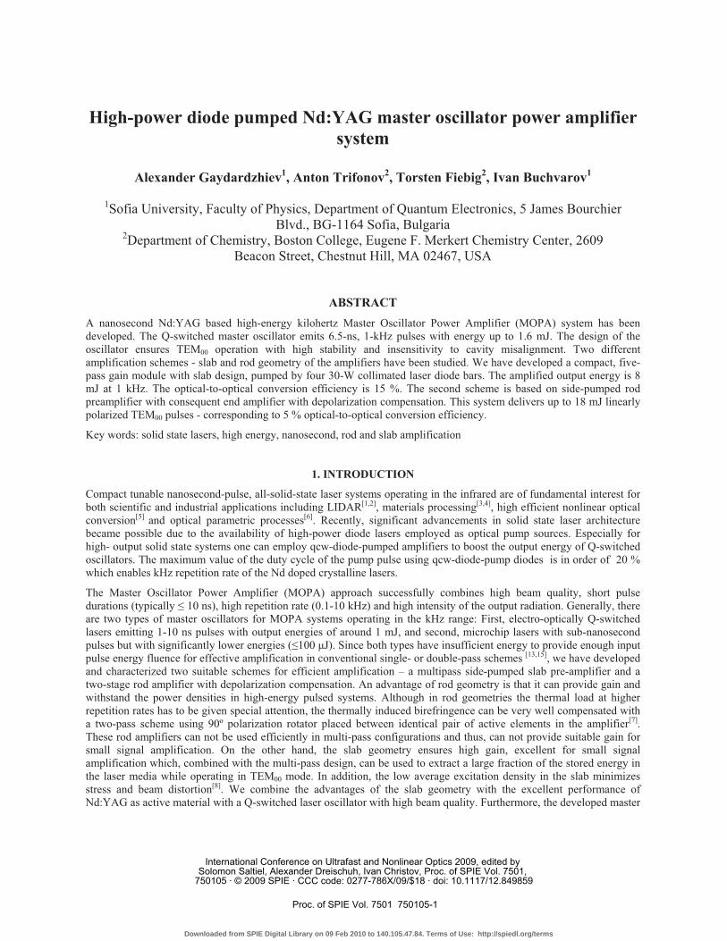
In order to obtain high output power and sufficiently short pulses, we have constructed a master oscillator with 155-mm resonator length (Fig.1), employing a 12-mm BBO Pockels cell as an electro-optic modulator. The high voltage Pockels cell driver easily supports tens of kHz repetition rates. The active element is 8-mm long Nd:YAG crystal end-pumped with up to 16 mJ, 1 kHz, 180-�s pulses from a fiber-coupled, 808-nm diode laser (JOLD 70 QPXF 1L). The oscillator is designed so that the pump beam size (around 600 �m) in the active element is equal to the fundamental TEM00 mode size of the cavity. Also, we have implemented a scheme with intracavity Dove- and Porro prisms (see Fig.1) in order to increase the stability of the resonator[10] against optical misalignment. As a necessary condition that ensures the efficiency of this method, the rear mirror mount and the optical coupler mount were assembled on a common rigid mechanical base. Experimentally was proven, that when the common base is tilted in the range of +- 20 mrad in both the vertical and horizontal plane, the output energy of the oscillator does not change substantially. Hence, this scheme is largely insensitive to misalignments caused by bending or twisting of the oscillator mechanical chassis.
Fig.1. Master oscillator schematic layout. The active element is an 1% Nd:YAG rod with 3 mm diameter and 8 mm length, fiber diameter is 600 �m, NA = 0.22, cavity length 155 mm, Porro prism bending the oscillator, 60 % transmission flat output coupler and a 12-mm BBO Pockels cell.
2.2. Nd:YAG slab amplifier module
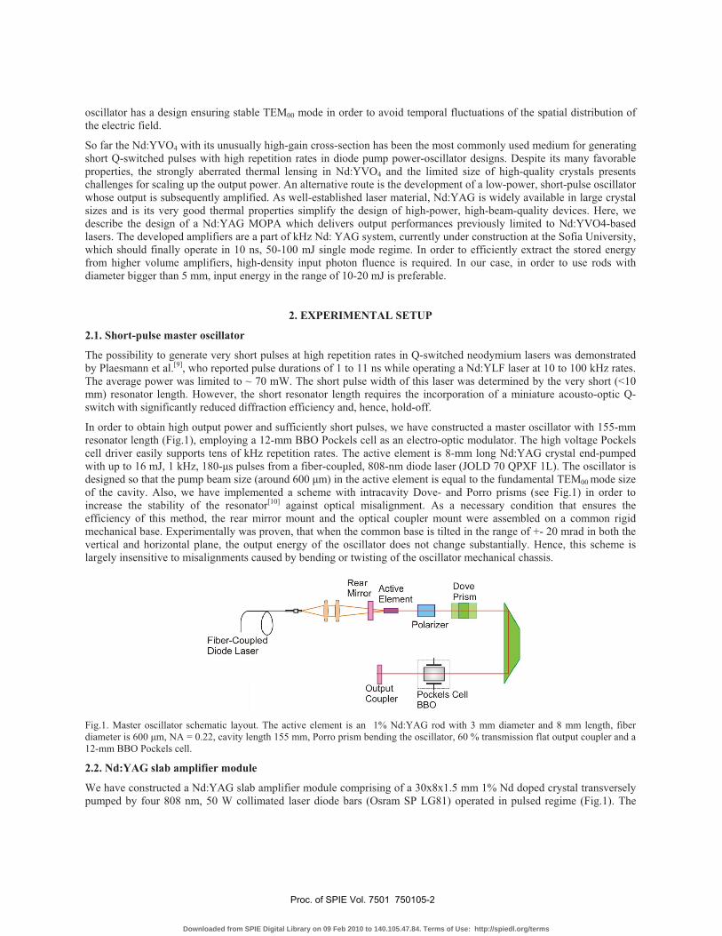
We have constructed a Nd:YAG slab amplifier module comprising of a 30x8x1.5 mm 1% Nd doped crystal transversely pumped by four 808 nm, 50 W collimated laser diode bars (Osram SP LG81) operated in pulsed regime (Fig.1). The
Proc. of SPIE Vol. 7501 750105-2
Downloaded from SPIE Digital Library on 09 Feb 2010 to 140.105.47.84. Terms of Use: http://spiedl.org/terms
active element was mounted on an actively-cooled copper heat sink. The laser diodes were mounted in specially designed holders made from high temperature resistant polymer, and thermally stabilized by a water cooling circuit. The diode bars were driven by a current driver delivering up to 100 A current pulses with variable duration and frequency. The fast-axis microlense collimation of each diode bar radiation ensures less than 1 degree divergence, resulting in an almost constant 7 x 0.4 mm beam over the whole width of the active element. Special precautions were taken to ensure that the emission of all four diode bars lays in one plane, parallel to the cooled surfaces of the crystal. The diode bars were offset in such fashion to avoid direct irradiation of the emitters from the opposing sides. The crystal absorption of the pump is close to 90 %. A system of two lenses was used to contract the 1mm beam diameter from the master oscillator to 400 �m, thus ensuring maximal overlap between the pumped height of the active element and the beam. The beam profile on entering the amplifier was close to round, but during propagation in the active media it is becoming elongated in the plane of pumping, which additionally enhances the amplifier efficiency by improving the overlap between the pumped volume and the amplified beam.
Fig.2. Scheme of the Nd:YAG slab amplifier module
2.3. Nd:YAG preamplifier and amplifier with polarization compensation
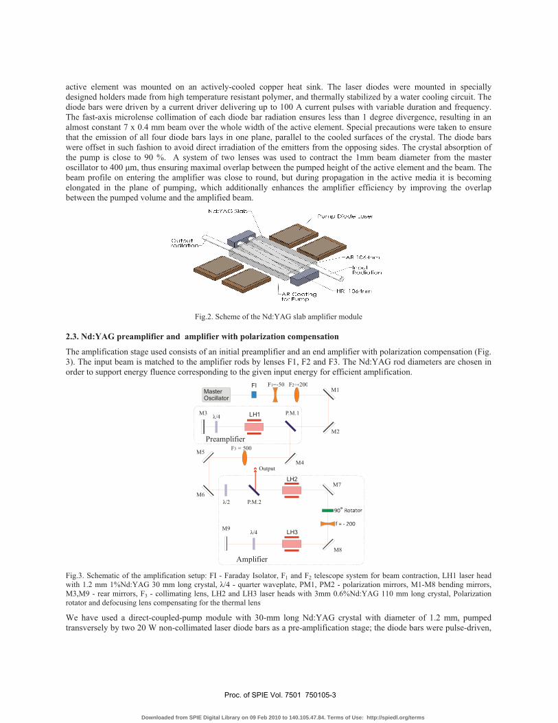
The amplification stage used consists of an initial preamplifier and an end amplifier with polarization compensation (Fig. 3). The input beam is matched to the amplifier rods by lenses F1, F2 and F3. The Nd:YAG rod diameters are chosen in order to support energy fluence corresponding to the given input energy for efficient amplification.
MasterOscillator
FI
M3 P.M.1
P.M.2
F = 500 3
Output
Amplifier
Preamplifier
M1F =-501 F 2002=+
M2
M4
M7
M8
M5
M6
M9�/4
�/2
�/4 LH1
LH2
LH3
Fig.3. Schematic of the amplification setup: FI - Faraday Isolator, F1 and F2 telescope system for beam contraction, LH1 laser head with 1.2 mm 1%Nd:YAG 30 mm long crystal, �/4 - quarter waveplate, PM1, PM2 - polarization mirrors, M1-M8 bending mirrors, M3,M9 - rear mirrors, F3 - collimating lens, LH2 and LH3 laser heads with 3mm 0.6%Nd:YAG 110 mm long crystal, Polarization rotator and defocusing lens compensating for the thermal lens
We have used a direct-coupled-pump module with 30-mm long Nd:YAG crystal with diameter of 1.2 mm, pumped transversely by two 20 W non-collimated laser diode bars as a pre-amplification stage; the diode bars were pulse-driven,
Proc. of SPIE Vol. 7501 750105-3
Downloaded from SPIE Digital Library on 09 Feb 2010 to 140.105.47.84. Terms of Use: http://spiedl.org/terms
providing up to 5 mJ pump energy at 200 �s pump pulse duration keeping the duty cycle up to 20%. A double-pass scheme with a quarter-wave plate in front of the back-reflecting mirror was used. The end amplifier consists of two identical modules each containing a 3-mm diameter, 90 mm long Nd:YAG rod, side pumped by fifteen 40-W, 808 nm laser diode bars, assembled in three-fold geometry.
The thermal load in our case has to be given specific attention, because of the high repetition rate and the substantial pump energy. Thermal loading can lead to degeneration of the beam quality not only by aberrations of the refractive index and thermal wedges but also by thermally induced birefringence. This effect can be very well compensated in rod geometry by introducing a quartz rotator placed between two identical amplification modules[11, 12]. Therefore a 90� polarization rotator between the two modules was used to compensate for the depolarization induced in the two Nd:YAG rods. Additionally a defocusing lens with 200 mm focal length was placed between the modules to compensate for the thermal lensing.
3. RESULTS AND DISCUSSION 3.1. Operation of the master oscillator
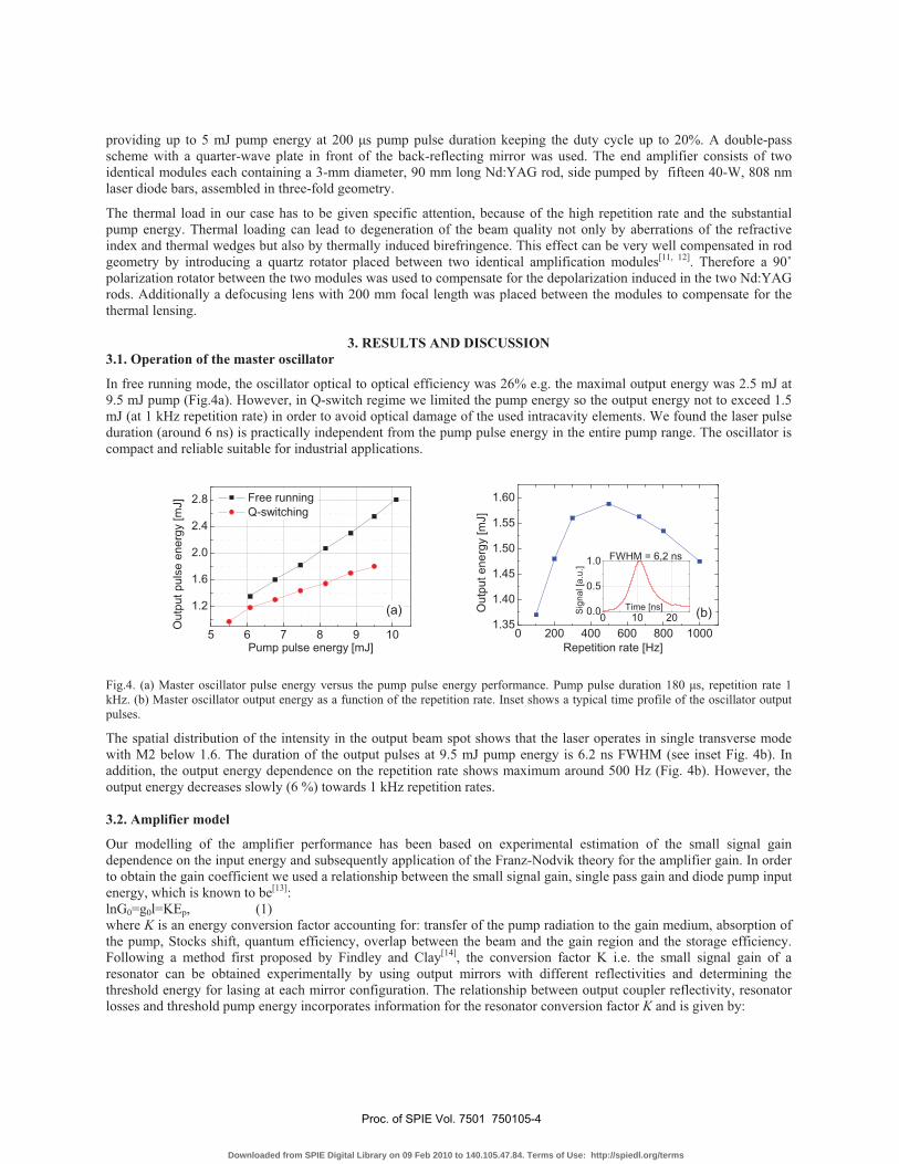
In free running mode, the oscillator optical to optical efficiency was 26% e.g. the maximal output energy was 2.5 mJ at 9.5 mJ pump (Fig.4a). However, in Q-switch regime we limited the pump energy so the output energy not to exceed 1.5 mJ (at 1 kHz repetition rate) in order to avoid optical damage of the used intracavity elements. We found the laser pulse duration (around 6 ns) is practically independent from the pump pulse energy in the entire pump range. The oscillator is compact and reliable suitable for industrial applications.
5 6 7 8 9 10
1.2
1.6
2.0
2.4
2.8 Free running Q-switching
Out
put p
ulse
ene
rgy
[mJ]
Pump pulse energy [mJ]
(a)
0 200 400 600 800 10001.35
1.40
1.45
1.50
1.55
1.60
O
utpu
t ene
rgy
[mJ]
Repetition rate [Hz]
(b)0 10 200.0
0.5
1.0
Sig
nal [
a.u.
]
Time [ns]
FWHM = 6,2 ns
Fig.4. (a) Master oscillator pulse energy versus the pump pulse energy performance. Pump pulse duration 180 �s, repetition rate 1 kHz. (b) Master oscillator output energy as a function of the repetition rate. Inset shows a typical time profile of the oscillator output pulses.
The spatial distribution of the intensity in the output beam spot shows that the laser operates in single transverse mode with M2 below 1.6. The duration of the output pulses at 9.5 mJ pump energy is 6.2 ns FWHM (see inset Fig. 4b). In addition, the output energy dependence on the repetition rate shows maximum around 500 Hz (Fig. 4b). However, the output energy decreases slowly (6 %) towards 1 kHz repetition rates. 3.2. Amplifier model
Our modelling of the amplifier performance has been based on experimental estimation of the small signal gain dependence on the input energy and subsequently application of the Franz-Nodvik theory for the amplifier gain. In order to obtain the gain coefficient we used a relationship between the small signal gain, single pass gain and diode pump input energy, which is known to be[13]: lnG0=g0l=KEp, (1) where K is an energy conversion factor accounting for: transfer of the pump radiation to the gain medium, absorption of the pump, Stocks shift, quantum efficiency, overlap between the beam and the gain region and the storage efficiency. Following a method first proposed by Findley and Clay[14], the conversion factor K i.e. the small signal gain of a resonator can be obtained experimentally by using output mirrors with different reflectivities and determining the threshold energy for lasing at each mirror configuration. The relationship between output coupler reflectivity, resonator losses and threshold pump energy incorporates information for the resonator conversion factor K and is given by:
Proc. of SPIE Vol. 7501 750105-4
Downloaded from SPIE Digital Library on 09 Feb 2010 to 140.105.47.84. Terms of Use: http://spiedl.org/terms
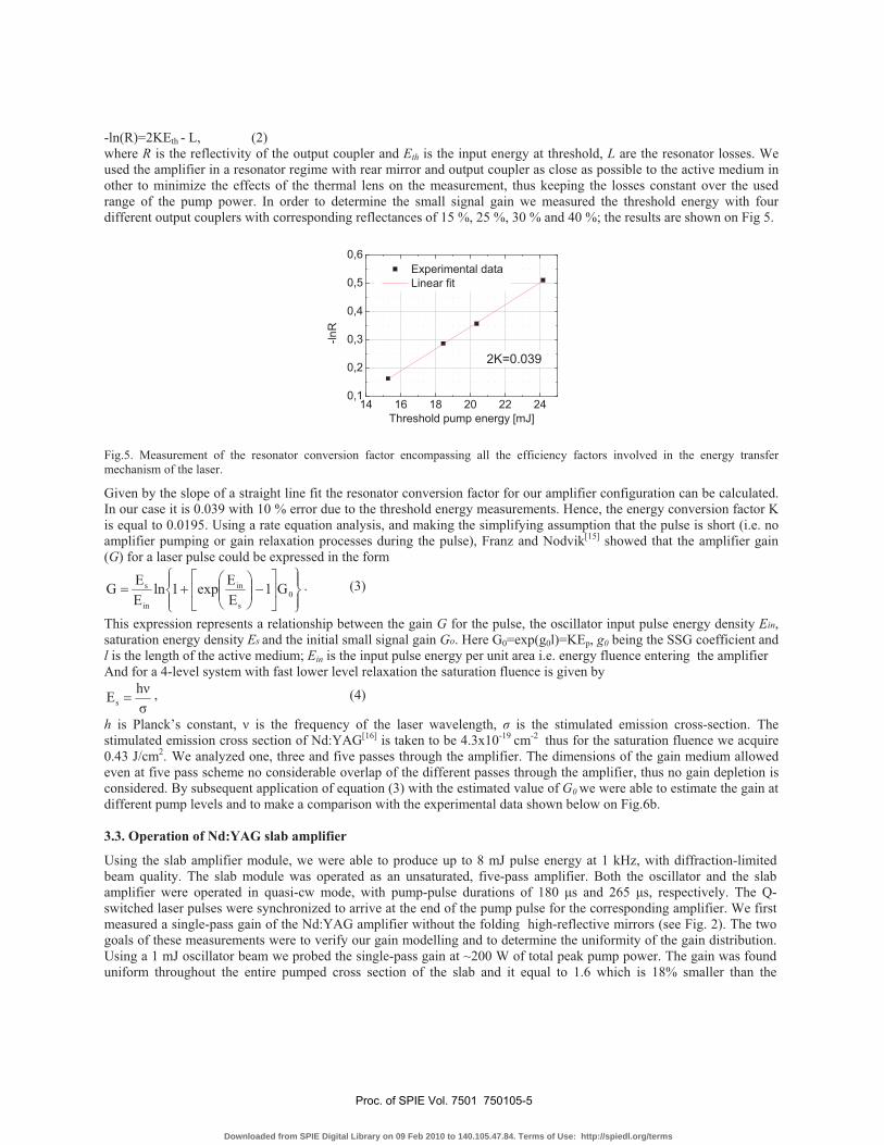
-ln(R)=2KEth - L, (2) where R is the reflectivity of the output coupler and Eth is the input energy at threshold, L are the resonator losses. We used the amplifier in a resonator regime with rear mirror and output coupler as close as possible to the active medium in other to minimize the effects of the thermal lens on the measurement, thus keeping the losses constant over the used range of the pump power. In order to determine the small signal gain we measured the threshold energy with four different output couplers with corresponding reflectances of 15 %, 25 %, 30 % and 40 %; the results are shown on Fig 5.
14 16 18 20 22 240,1
0,2
0,3
0,4
0,5
0,6
2K=0.039
Experimental data Linear fit
-lnR
Threshold pump energy [mJ]
Fig.5. Measurement of the resonator conversion factor encompassing all the efficiency factors involved in the energy transfer mechanism of the laser.
Given by the slope of a straight line fit the resonator conversion factor for our amplifier configuration can be calculated. In our case it is 0.039 with 10 % error due to the threshold energy measurements. Hence, the energy conversion factor K is equal to 0.0195. Using a rate equation analysis, and making the simplifying assumption that the pulse is short (i.e. no amplifier pumping or gain relaxation processes during the pulse), Franz and Nodvik[15] showed that the amplifier gain (G) for a laser pulse could be expressed in the form
��
���
��
���
��
�����
����
��� 0
s
in
in
s G1EEexp1ln
EEG . (3)
This expression represents a relationship between the gain G for the pulse, the oscillator input pulse energy density Ein, saturation energy density Es and the initial small signal gain Go. Here G0=exp(g0l)=KEp, g0 being the SSG coefficient and l is the length of the active medium; Ein is the input pulse energy per unit area i.e. energy fluence entering the amplifier And for a 4-level system with fast lower level relaxation the saturation fluence is given by
�h��s � , (4)
h is Planck’s constant, � is the frequency of the laser wavelength, � is the stimulated emission cross-section. The stimulated emission cross section of Nd:YAG[16] is taken to be 4.3x10⁻¹⁹ cm-2 thus for the saturation fluence we acquire 0.43 J/cm2. We analyzed one, three and five passes through the amplifier. The dimensions of the gain medium allowed even at five pass scheme no considerable overlap of the different passes through the amplifier, thus no gain depletion is considered. By subsequent application of equation (3) with the estimated value of G0 we were able to estimate the gain at different pump levels and to make a comparison with the experimental data shown below on Fig.6b. 3.3. Operation of Nd:YAG slab amplifier
Using the slab amplifier module, we were able to produce up to 8 mJ pulse energy at 1 kHz, with diffraction-limited beam quality. The slab module was operated as an unsaturated, five-pass amplifier. Both the oscillator and the slab amplifier were operated in quasi-cw mode, with pump-pulse durations of 180 �s and 265 �s, respectively. The Q-switched laser pulses were synchronized to arrive at the end of the pump pulse for the corresponding amplifier. We first measured a single-pass gain of the Nd:YAG amplifier without the folding high-reflective mirrors (see Fig. 2). The two goals of these measurements were to verify our gain modelling and to determine the uniformity of the gain distribution. Using a 1 mJ oscillator beam we probed the single-pass gain at ~200 W of total peak pump power. The gain was found uniform throughout the entire pumped cross section of the slab and it equal to 1.6 which is 18% smaller than the
Proc. of SPIE Vol. 7501 750105-5
Downloaded from SPIE Digital Library on 09 Feb 2010 to 140.105.47.84. Terms of Use: http://spiedl.org/terms
calculated value 1.9 using relation (3). We attribute this difference due to the overlapping between the pump region in the slab and input beam which are not taken into account in the method of K measurement.
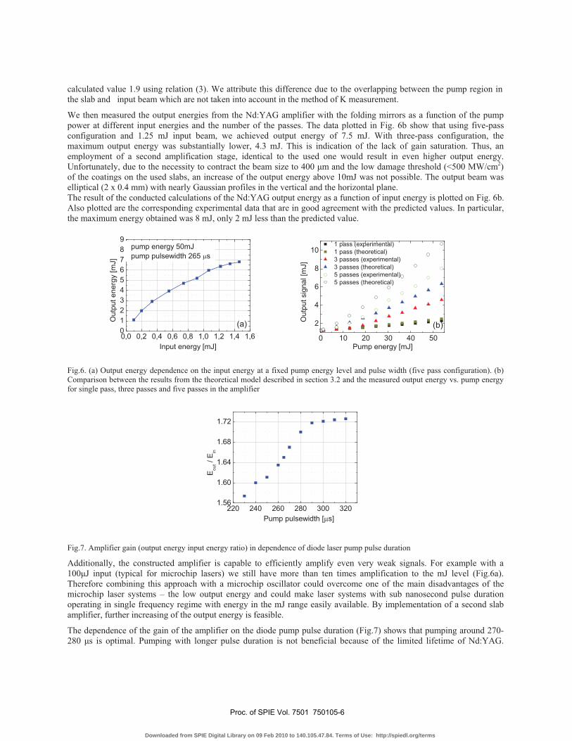
We then measured the output energies from the Nd:YAG amplifier with the folding mirrors as a function of the pump power at different input energies and the number of the passes. The data plotted in Fig. 6b show that using five-pass configuration and 1.25 mJ input beam, we achieved output energy of 7.5 mJ. With three-pass configuration, the maximum output energy was substantially lower, 4.3 mJ. This is indication of the lack of gain saturation. Thus, an employment of a second amplification stage, identical to the used one would result in even higher output energy. Unfortunately, due to the necessity to contract the beam size to 400 �m and the low damage threshold (<500 MW/cm2) of the coatings on the used slabs, an increase of the output energy above 10mJ was not possible. The output beam was elliptical (2 x 0.4 mm) with nearly Gaussian profiles in the vertical and the horizontal plane. The result of the conducted calculations of the Nd:YAG output energy as a function of input energy is plotted on Fig. 6b. Also plotted are the corresponding experimental data that are in good agreement with the predicted values. In particular, the maximum energy obtained was 8 mJ, only 2 mJ less than the predicted value.
0,0 0,2 0,4 0,6 0,8 1,0 1,2 1,4 1,60123456789
Out
put e
nerg
y [m
J]
Input energy [mJ]
pump energy 50mJpump pulsewidth 265 �s
(a)
0 10 20 30 40 50
2
4
6
8
10
1 pass (experimental) 1 pass (theoretical) 3 passes (experimental) 3 passes (theoretical) 5 passes (experimental) 5 passes (theoretical)
Out
put s
igna
l [m
J]
Pump energy [mJ]
(b)
Fig.6. (a) Output energy dependence on the input energy at a fixed pump energy level and pulse width (five pass configuration). (b) Comparison between the results from the theoretical model described in section 3.2 and the measured output energy vs. pump energy for single pass, three passes and five passes in the amplifier
220 240 260 280 300 3201.56
1.60
1.64
1.68
1.72
E out /
E in
Pump pulsewidth [�s]
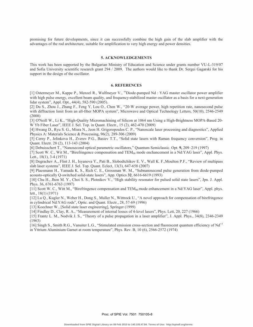
Fig.7. Amplifier gain (output energy input energy ratio) in dependence of diode laser pump pulse duration
Additionally, the constructed amplifier is capable to efficiently amplify even very weak signals. For example with a 100�J input (typical for microchip lasers) we still have more than ten times amplification to the mJ level (Fig.6a). Therefore combining this approach with a microchip oscillator could overcome one of the main disadvantages of the microchip laser systems – the low output energy and could make laser systems with sub nanosecond pulse duration operating in single frequency regime with energy in the mJ range easily available. By implementation of a second slab amplifier, further increasing of the output energy is feasible.
The dependence of the gain of the amplifier on the diode pump pulse duration (Fig.7) shows that pumping around 270-280 �s is optimal. Pumping with longer pulse duration is not beneficial because of the limited lifetime of Nd:YAG.
Proc. of SPIE Vol. 7501 750105-6
Downloaded from SPIE Digital Library on 09 Feb 2010 to 140.105.47.84. Terms of Use: http://spiedl.org/terms

However, from the plot in Fig. 7 it is obvious that there is possibility to increase further the pump length but it will be at the cost of reduced efficiency. Longer pump durations than 300 �s are neither effective nor will give any increase of the output power. Finally, around 70 % of the output light is linearly polarized, the depolarization is due to the thermally induced birefringence in Nd:YAG.
3.4. Operation of Nd:YAG rod pre-amplifier and end amplifier with polarization compensation
When the of the oscillator pulses were amplified with the rod preamplifier, Nd:YAG crystal was pumped in QCW regime (pulse duration 270 �s). The design of the module specifically ensures homogenous pump distribution through the whole crystal cross-section. With input beam energy of 1.2 mJ at maximum pump power we were able to obtain more than 2.2 mJ (Fig.8a) of linearly polarized light. Even though the efficiency of this system is quite low (~ 4 %) due to the low input fluence from the oscillator, it preserves the oscillator beam quality and gives enough additional energy to increase the effectiveness of the amplifier (without the pre-amplification stage we achieved 10 mJ from the amplifier).
The amplifier was operated at pump pulse width of 270 �s and synchronized with both the preamplifier and the master oscillator. The diode bars of the two modules were driven in pulsed mode at 800 Hz - in this scheme the frequency is lower that the slab geometry in order to avoid thermal damage of the pump diode bars.
0 10 20 30 40
1.2
1.4
1.6
1.8
2.0
2.2
2.4
Pre
ampl
ifier
out
put e
nerg
y [m
J]
Optical pump energy [mJ]
pulse duration 6.5 ns
330 340 350 360 370 380 390 400468
101214161820
pulse duration 6.5 ns
Am
plifi
er o
utpu
t ene
rgy
[mJ]
Optical pump energy [mJ]
Fig.8. (a) Performance of the preamplifier (CW pumped). (b) Performance of the amplifier at pump pulse width of 270 �s.
The two laser heads were exactly identical in terms of design, pump geometry, active crystal doping. Furthermore the diodes used in them were from the same batch with identical characteristics. All this was necessary for the polarization compensation scheme to work effectively. The dependence of the amplified signal on the input energy is almost linear, showing no gain saturation. With input energy of 2.2 mJ at higher pump power we were able to achieve 18 mJ of linearly polarized light corresponding to an optical to optical conversion efficiency of ~ 4.5 %. The quality of the output beam is excellent with no apparent hot spots and with visibly circular Gaussian distribution. The pulse duration is similar to the input beam pulse duration within ± 10%.
Having output energy level above ten mJ, the proposed rod amplifier design with polarization compensation can be used as a first stage of a nanosecond laser system, power scaled with 6-10 mm diameter YAG rods up to 100 mJ per pulse at 100 W average power. Short pulse laser source combining a high repetition rate (0.5-1 kHz) with pulse energy ranging 50-100 mJ will be an effective tool for laser material ablation, providing high throughput of the ablation process. Even though such IR lasers are not available so far, there are strongly demanded by the laser industry in a variety of applications in material science and medicine.
4. CONCLUSION
We have developed a master oscillator power amplifier system with two alternative designs: slab and rod geometries. We were able to provide high energy and high-power output from Nd:YAG slab amplifier with combination of short pulse duration and high repetition rate, typical only for Nd:YVO4 lasers. The comparison between the two schemes shows that though the output pulse energy of the rod amplifier is higher, its efficiency is lower than for the slab design. The two concepts can be complimentary to each other, e.g. a slab amplifier can be used as a preamplification stage to an amplifier with depolarization compensation, provided that the ellipticity of the slab output is compensated. We find this scheme
Proc. of SPIE Vol. 7501 750105-7
Downloaded from SPIE Digital Library on 09 Feb 2010 to 140.105.47.84. Terms of Use: http://spiedl.org/terms
promising for future developments, since it can successfully combine the high gain of the slab amplifier with the advantages of the rod architecture, suitable for amplification to very high energy and power densities.
5. ACKNOWLEDGEMENTS
This work has been supported by the Bulgarian Ministry of Education and Science under grants number VU-L-319/07 and Sofia University scientific research grant 294 / 2009. The authors would like to thank Dr. Sergei Gagarski for his support in the design of the oscillator.
6. REFERENCES
[1] Ostermeyer M., Kappe P., Menzel R., Wulfmeyer V., “Diode-pumped Nd : YAG master oscillator power amplifier with high pulse energy, excellent beam quality, and frequency-stabilized master oscillator as a basis for a next-generation lidar system”, Appl. Opt., 44(4), 582-590 (2005). [2] Du S., Zhou J., Zhang F., Feng Y, Lou O., Chen W., “20-W average power, high repetition rate, nanosecond pulse with diffraction limit from an all-fiber MOPA system”, Microwave and Optical Technology Letters, 50(10), 2546-2549 (2008) [3] O'Neill W., Li K., “High-Quality Micromachining of Silicon at 1064 nm Using a High-Brightness MOPA-Based 20-W Yb Fiber Laser”, IEEE J. Sel. Top. in Quant. Electr., 15 (2), 462-470 (2009) [4] Hwang D., Ryu S. G., Misra N., Jeon H. Grigoropoulos C. P., “Nanoscale laser processing and diagnostics”, Applied Physics A: Materials Science & Processing, 96(2), 289-306 (2009) [5] Cerny P., Jelinkova H., Zverev P.G., Basiev T.T., “Solid state lasers with Raman frequency conversion”, Prog. in Quant. Electr. 28 (2), 113-143 (2004) [6] Debuisschert T., “Nanosecond optical parametric oscillators,” Quantum Semiclassic. Opt. 9, 209–219 (1997) [7] Scott W. C., Wit M., “Birefringence compensation and TEM00 mode enchancement in a Nd:YAG laser”, Appl. Phys. Lett., 18(1), 3-4 (1971) [8] Degrachev A., Flint J. H., Isyanova Y., Pati B., Slobodtchikov E. V., Wall K. F.,Moulton P.F., “Review of multipass slab laser systems”, IEEE J. Sel. Top. Quant. Eclect, 13(3), 647-658 (2007) [9] Plaesmann H., Yamada K. S., Rich C. E., Grossman W. M., “Subnanosecond pulse generation from diode-pumped acousto-optically Q-switched solid-state lasers”, App. Optics 32, 6616-6619 (1993) [10] Chu H., Jhon M. Y., Choi S. S., Plotnikov V., “High stability resonator for pulsed solid state lasers”, Jpn. J. Appl. Phys. 36, 6761-6763 (1997) [11] Scott W. C., Witt M., “Birefringence compensation and TEM00 mode enhancement in a Nd:YAG laser”, Appl. phys. lett., 18(1) (1971) [12] Lu Q., Kugler N., Weber H., Dong S., Muller N., Wittrock U., “A novel approach for compensation of birefringence in cylindrical Nd:YAG rods”, Optic. and Quant. Electr., 28, 57-69 (1996) [13] Koechner W., [Solid state laser engineering], Springer (1999) [14] Findlay D., Clay, R. A., “Measurement of internal losses of 4-level lasers”, Phys. Lett, 20, 227 (1966) [15] Frantz L. M., Nodvik J. S., “Theory of a pulse propagation in a laser amplifier”, J. Appl. Phys., 34(8), 2346-2349 (1963) [16] Singh S., Smith R.G., Vanuiter L.G., “Stimulated emission cross-section and fluorescent quantum efficiency of Nd+3 in Yttrium Aluminium Garnet at room temperature”, Phys. Rev. B, 10 (6), 2566-2572 (1974)
Proc. of SPIE Vol. 7501 750105-8
Downloaded from SPIE Digital Library on 09 Feb 2010 to 140.105.47.84. Terms of Use: http://spiedl.org/terms