Embed Size (px)
Citation preview

High Power DC Electronic Load
63200 SeriesOperation & Programming Manual


High Power DC Electronic Load
63200 Series Operation & Programming
Manual
Version 2.4 November 2011 P/N A11 000599

ii
Legal Notices The information in this document is subject to change without notice. Chroma ATE INC. makes no warranty of any kind with regard to this manual, including, but not limited to, the implied warranties of merchantability and fitness for a particular purpose. Chroma ATE INC. shall not be held liable for errors contained herein or direct, indirect, special, incidental or consequential damages in connection with the furnishing, performance, or use of this material. CHROMA ATE INC. 66 Hwa-Ya 1st Rd., Hwa-Ya Technology Park, Kuei-Shan 33383, Taoyuan Hsien, Taiwan Copyright Notices. Copyright 2003 Chroma ATE INC., all rights reserved. Reproduction, adaptation, or translation of this document without prior written permission is prohibited, except as allowed under the copyright laws.

iii
Warranty All Chroma instruments are warranted against defects in material and workmanship for a period of one year after date of shipment. Chroma agrees to repair or replace any assembly or component found to be defective, under normal use during this period. Chroma’s obligation under this warranty is limited solely to repairing any such instrument, which in Chroma’s sole opinion proves to be defective within the scope of the warranty when returned to the factory or to an authorized service center. Transportation to the factory or service center is to be prepaid by purchaser. Shipment should not be made without prior authorization by Chroma. This warranty does not apply to any products repaired or altered by persons not authorized by Chroma, or not in accordance with instructions furnished by Chroma. If the instrument is defective as a result of misuse, improper repair, or abnormal conditions or operations, repairs will be billed at cost. Chroma assumes no responsibility for its product being used in a hazardous or dangerous manner either alone or in conjunction with other equipment. High voltage used in some instruments may be dangerous if misused. Special disclaimers apply to these instruments. Chroma assumes no liability for secondary charges or consequential damages and in any event, Chroma’s liability for breach of warranty under any contract or otherwise, shall not exceed the purchase price of the specific instrument shipped and against which a claim is made. Any recommendations made by Chroma for use of its products are based upon tests believed to be reliable, but Chroma makes no warranty of the results to be obtained. This warranty is in lieu of all other warranties, expressed or implied, and no representative or person is authorized to represent or assume for Chroma any liability in connection with the sale of our products other than set forth herein. CHROMA ATE INC. 66 Hwa-Ya 1st Rd., Hwa-Ya Technology Park, Kuei-Shan 33383, Taoyuan County, Taiwan Tel: 886-3-327-9999 Fax: 886-3-327-2886 e-mail: [email protected] http://www.chromaate.com
iv
Material Contents Declaration The recycling label shown on the product indicates the Hazardous Substances contained in the product as the table listed below.
: See <Table 1>.
: See <Table 2>. <Table 1>
Hazardous Substances Lead Mercury Cadmium Hexavalent
ChromiumPolybrominated
Biphenyls Polybromodiphenyl
Ethers Part Name
Pb Hg Cd Cr6+ PBB PBDE
PCBA O O O O O O
CHASSIS O O O O O O
ACCESSORY O O O O O O
PACKAGE O O O O O O “O” indicates that the level of the specified chemical substance is less than the threshold level specified in the standards of SJ/T-11363-2006 and EU 2005/618/EC. “ ” indicates that the level of the specified chemical substance exceeds the threshold level specified in the standards of SJ/T-11363-2006 and EU 2005/618/EC.
Disposal Do not dispose of electrical appliances as unsorted municipal waste, use separate collection facilities. Contact your local government for information regarding the collection systems available. If electrical appliances are disposed of in landfills or dumps, hazardous substances can leak into the groundwater and get into the food chain, damaging your health and well-being. When replacing old appliances with new one, the retailer is legally obligated to take back your old appliances for disposal at least for free of charge.
v
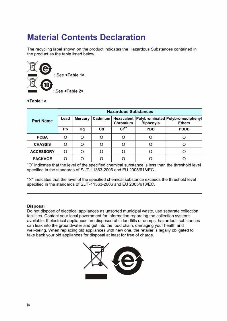
<Table 2>
Hazardous Substances Lead Mercury Cadmium Hexavalent
ChromiumPolybrominated
Biphenyls Polybromodiphenyl
Ethers Part Name
Pb Hg Cd Cr6+ PBB PBDE
PCBA O O O O O
CHASSIS O O O O O
ACCESSORY O O O O O
PACKAGE O O O O O O “O” indicates that the level of the specified chemical substance is less than the threshold level specified in the standards of SJ/T-11363-2006 and EU 2005/618/EC. “ ” indicates that the level of the specified chemical substance exceeds the threshold level specified in the standards of SJ/T-11363-2006 and EU 2005/618/EC. 1. Chroma is not fully transitioned to lead-free solder assembly at this moment; however,
most of the components used are RoHS compliant. 2. The environment-friendly usage period of the product is assumed under the operating
environment specified in each product’s specification. Disposal Do not dispose of electrical appliances as unsorted municipal waste, use separate collection facilities. Contact your local government for information regarding the collection systems available. If electrical appliances are disposed of in landfills or dumps, hazardous substances can leak into the groundwater and get into the food chain, damaging your health and well-being. When replacing old appliances with new one, the retailer is legally obligated to take back your old appliances for disposal at least for free of charge.

vi
CE-Conformity Declaration For the following equipment: Product Name: DC Electronic Load Model Name:63201, 63202, 63203, 63204, 63205, 63206, 63207, 63208, 63209 ,63210 Manufacturer’s Name: Chroma ATE Inc. Manufacturer’s Address: 66 Hwa-Ya 1st Rd., Hwa-Ya Technical Park, Kuei-Shan Hsiang, Taoyuan Hsien, Taiwan is herewith confirmed to comply with the requirements set out in the Council Directive on the Approximation of the Laws of the Member States Relating to Electromagnetic Compatibility (89/336/EEC) and electrical equipment designed for use within certain voltage limits (73/23/EEC;93/68/EEC) For electromagnetic compatibility, the following standards were applied: EMC: EN61326-1(1997):CISPR22:1994+A1 Class A IEC 1000-3-2:1995 Harmonics Current IEC 1000-3-3:1995 Voltage Fluctuations IEC 1000-4-2:1995 Electrostatic Discharge IEC 1000-4-3:1995 Radio-Frequency Electromagnetic Field IEC 1000-4-4:1995 Fast Transient Burst IEC 1000-4-5:1995 Surge Immunity test IEC 1000-4-6:1995 Immunity To Conducted Disturbances, Induced By Radio Frequency Fields IEC 1000-4-11:1994 Voltage Dips, Short Interruptions and Voltage Variations Immunity Test For safety requirement, the following standard was applied: Safety: EN61010-1(1993)+A2(1995)
Taiwan May 2005 Place Date Vice President, Engineering
Warning: This is a class A product. In a domestic environment this product may cause radio interference in which case the user may be required to take adequate measures.

vii
Safety Summary The following general safety precautions must be observed during all phases of operation, service, and repair of this instrument. Failure to comply with these precautions or specific WARNINGS given elsewhere in this manual will violate safety standards of design, manufacture, and intended use of the instrument. Chroma assumes no liability for the customer’s failure to comply with these requirements.
BEFORE APPLYING POWER Verify that the power is set to match the rated input of this power supply.
PROTECTIVE GROUNDING Make sure to connect the protective grounding to prevent an electric shock before turning on the power.
NECESSITY OF PROTECTIVE GROUNDING Never cut off the internal or external protective grounding wire, or disconnect the wiring of protective grounding terminal. Doing so will cause a potential shock hazard that may bring injury to a person.
FUSES Only fuses with the required rated current, voltage, and specified type (normal blow, time delay, etc.) should be used. Do not use repaired fuses or short-circuited fuse holders. To do so could cause a shock or fire hazard.
DO NOT OPERATE IN AN EXPLOSIVE ATMOSPHERE Do not operate the instrument in the presence of flammable gases or fumes. The instrument should be used in an environment of good ventilation.
DO NOT REMOVE THE COVER OF THE INSTRUMENT Operating personnel must not remove the cover of the instrument. Component replacement and internal adjustment can be done only by qualified service personnel.
viii
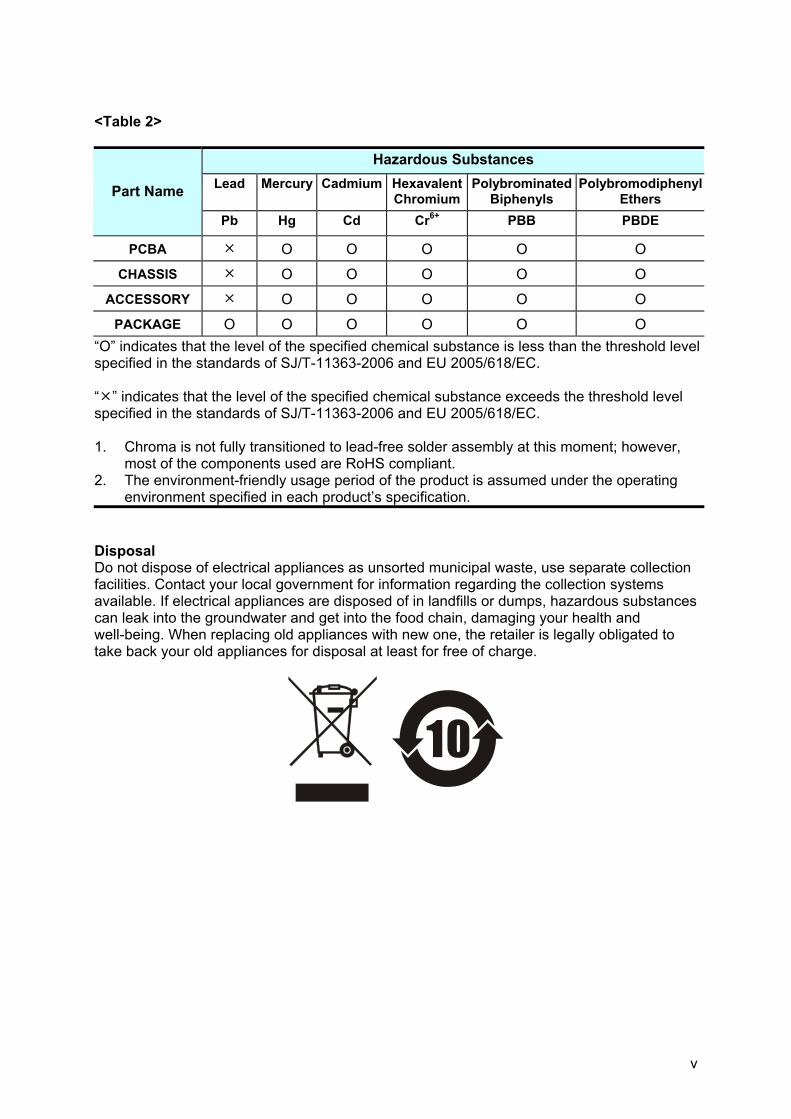
Safety Symbols
DANGER – High voltage.
Explanation: To avoid injury, death of personnel, or damage to the instrument, the operator must refer to an explanation in the instruction manual.
High temperature: This symbol indicates the temperature is now higher than the acceptable range of human. Do not touch it to avoid any personal injury.
Protective grounding terminal: To protect against electrical shock in case of a fault. This symbol indicates that the terminal must be connected to ground before operation of equipment.
WARNING
The WARNING sign denotes a hazard. It calls attention to a procedure, practice, or the like, which, if not correctly performed or adhered to, could result in personal injury. Do not proceed beyond a WARNING sign until the indicated conditions are fully understood and met.
CAUTIONThe CAUTION sign denotes a hazard. It may result in personal injury or death if not noticed timely. It calls attention to procedures, practices and conditions.
The Notice sign denotes important information in procedures, applications or the areas that require special attention. Be sure to read it carefully.

ix
Revision History The following lists the additions, deletions and modifications in this manual at each revision. Date Version Revised Sections Mar. 2003 1.3 Update “CE Conformity Declaration” to add model 63205/63207/63209
Update “Specifications” for changes and addition of model 63205/63207/ 63209 Add the rear panel of Model 63205/630206/63207/63208/63209 in “Rear Panel Description”
May 2003 1.4 Add a note to the “Specifications” for the fuse of 63205 Jan. 2004 1.5 Modify the “Specifications” in Chapter 1 for power rating changes for
all models. Add a section of “Dimension Outline for 63200 Series” in Chapter 1.
Jan. 2005 1.6 Add the following sections: – “Diagram of RS485 Parallel Connections” in Chapter 2. – “Load Surge Capability” in Chapter 3. – “Timer Function for Battery Discharge Testing” in Chapter 3. Modify the following sections: – “Specifications” in Chapter 1. – “Protection Features” in Chapter 3.
Jun. 2005 1.7 Change the address of Chroma in CE-Conformity Declaration Nov. 2005 1.8 Modify the “Specifications” in Chapter 1. Jun. 2006 1.9 Modify the followings:
– “Specifications” to add a new model 63210. – Description in the section of “Parallel Connections”. – “Load Connections” in the section of “Application Connection”. – Commands in the chapter of “Language Dictionary”. – “Questionable Status” in the chapter of “Status Reporting”. – “Command Summary” in the chapter of “Index”. Add “Installing the 63200 Protective Cover” in the section of “Dimension Outline for 63200 Series”.
Dec. 2006 2.0 Add the following: – “Von Protection”, “CR Offset Error Compensation” and the GPIB
related commands in the chapters of “Operation Overview”, “Local Operation” and “Language Dictionary”.
– “Battery Discharge” and the GPIB related commands in the chapters of “Local Operation” and “Language Dictionary”.
Modify the contents of “Voltage & Current Monitor” in the chapter of “Operation Overview”.
Mar. 2007 2.1 Add “Material Contents Declaration”. Mar. 2008 2.2 Delete GPIB cable from the section of “Inspection” in the chapter of
“Installation.” Modify the contents of “Load Connections” in the chapter of “Installation.” Modify the figure of “Timer Function for Battery Discharge Testing” in the chapter of “Operation Overview.”
July 2009 2.3 Add Battery commands to the section of “Command Summary.” Update the detail specifications and descriptions in the table of “Specification” section.
Nov. 2010 2.4 Add the following: – “Parallel Setting” in the chapter of “Installation”

x
– “External LOAD ON/OFF Control” in the chapter of ”Operation Overview”
– “Troubleshooting” and “Precautions for Loading 63200 Battery” two chapters
Update the following: – Detail specifications and descriptions in “Specification” section – Front and rear panel descriptions – Standard accessories

High Power DC Electronic Load 63200 Series Operation & Programming Manual
xi
Table of Contents 1. General Information ............................................................................................... 1-1
1.1 Introduction....................................................................................................... 1-1 1.2 Description........................................................................................................ 1-1 1.3 Overview of Key Features ................................................................................ 1-2 1.4 Specifications ................................................................................................... 1-2 1.5 Dimension Outline for 63200 Series............................................................... 1-11
2. Installation .............................................................................................................. 2-1 2.1 Introduction....................................................................................................... 2-1 2.2 Inspection ......................................................................................................... 2-1 2.3 Installing ........................................................................................................... 2-1
2.3.1 Changing Line Voltage ............................................................................. 2-2 2.3.2 Turn-On Self-Test ..................................................................................... 2-2
2.4 Application Connection..................................................................................... 2-3 2.4.1 Load Connections..................................................................................... 2-3 2.4.2 Remote Sensing Connections .................................................................. 2-5 2.4.3 Parallel Connections................................................................................. 2-5 2.4.4 RS-485 Parallel Connection Diagram....................................................... 2-6 2.4.5 Parallel Setting.......................................................................................... 2-7
2.5 Remote Control Connection ........................................................................... 2-10 3. Operation Overview ............................................................................................... 3-1
3.1 Introduction....................................................................................................... 3-1 3.2 Front Panel Description .................................................................................... 3-1 3.3 Rear Panel Description..................................................................................... 3-1 3.4 Local/Remote Control ....................................................................................... 3-3 3.5 Modes of Operation .......................................................................................... 3-4
3.5.1 Constant Current Mode ............................................................................ 3-4 3.5.2 Constant Resistance Mode....................................................................... 3-6 3.5.3 Constant Voltage Mode ............................................................................ 3-7 3.5.4 Constant Power Mode .............................................................................. 3-7 3.5.5 Load Surge Capability .............................................................................. 3-8 3.5.6 Timer Function for Battery Discharge Testing .......................................... 3-9
3.6 Measurements................................................................................................ 3-10 3.7 Slew Rate & Minimum Transient Time ........................................................... 3-10 3.8 Start/Stop Current Loading............................................................................. 3-11 3.9 Short On/Off ................................................................................................... 3-12 3.10 Load On/Off .................................................................................................... 3-13 3.11 Protection Features ........................................................................................ 3-13 3.12 Save/Recall Setting ........................................................................................ 3-14 3.13 Program.......................................................................................................... 3-15 3.14 External Waveform Control............................................................................. 3-15 3.15 Voltage & Current Monitor .............................................................................. 3-15 3.16 Von Protection ................................................................................................ 3-15 3.17 CR Offset Error Compensation....................................................................... 3-18 3.18 External LOAD ON/OFF Control..................................................................... 3-18
4. Local Operation ...................................................................................................... 4-1 4.1 Introduction....................................................................................................... 4-1 4.2 Local Operation ................................................................................................ 4-1
4.2.1 Setting the Operation Mode...................................................................... 4-3 4.2.2 Setting the Program.................................................................................. 4-9 4.2.3 Running the Program.............................................................................. 4-11

High Power DC Electronic Load 63200 Series Operation & Programming Manual
xii
4.2.4 Setting the Specification ......................................................................... 4-12 4.2.5 Setting the Configuration ........................................................................ 4-12 4.2.6 Recalling Files ........................................................................................ 4-16 4.2.7 Saving File/Default/Program................................................................... 4-17 4.2.8 Going To Local ....................................................................................... 4-17 4.2.9 Setting System and RS-232C Connection.............................................. 4-17 4.2.10 Online Change Level .............................................................................. 4-18
5. Basic Information for Programming..................................................................... 5-1 5.1 Introduction....................................................................................................... 5-1
5.1.1 Setting the GPIB Address and RS-232C Parameters............................... 5-1 5.1.2 Wire Connection of RS-232C ................................................................... 5-1
5.2 GPIB Capability of the Electronic Load ............................................................ 5-2 5.3 RS-232C in Remote Control ............................................................................. 5-3
6. Introduction to Programming................................................................................ 6-1 6.1 Basic Definition................................................................................................. 6-1 6.2 Numerical Data Formats................................................................................... 6-2 6.3 Character Data Formats ................................................................................... 6-2 6.4 Separators and Terminators............................................................................. 6-3
7. Language Dictionary.............................................................................................. 7-1 7.1.1 Common Commands................................................................................ 7-1 7.1.2 Common Command Dictionary................................................................. 7-1
7.2 Specific Commands.......................................................................................... 7-4 7.2.1 CONFigure Sub-system............................................................................ 7-5 7.2.2 COMMunicate Sub-system....................................................................... 7-9 7.2.3 CURRENT Sub-system .......................................................................... 7-11 7.2.4 FETCh Sub-system ................................................................................ 7-14 7.2.5 LOAD Sub-system .................................................................................. 7-15 7.2.6 MEASure Sub-system ............................................................................ 7-17 7.2.7 MODE Sub-system ................................................................................. 7-19 7.2.8 POWer Sub-system ................................................................................ 7-20 7.2.9 PROGram Sub-system ........................................................................... 7-21 7.2.10 RESistance Sub-system ......................................................................... 7-24 7.2.11 SPECification Sub-system...................................................................... 7-25 7.2.12 STATus Sub-system............................................................................... 7-27 7.2.13 VOLTage Sub-system ............................................................................ 7-29 7.2.14 SYSTem Sub-system ............................................................................. 7-31
8. Status Reporting..................................................................................................... 8-1 8.1 Introduction....................................................................................................... 8-1 8.2 Register Information in Common...................................................................... 8-1 8.3 Questionable Status ......................................................................................... 8-2 8.4 Output Queue ................................................................................................... 8-3 8.5 Standard Event Status...................................................................................... 8-4 8.6 Status Byte Register ......................................................................................... 8-4 8.7 Service Request Enable Register..................................................................... 8-5
9. Command Index ..................................................................................................... 9-1 9.1 Command Summary......................................................................................... 9-1 9.2 Parallel Operation............................................................................................. 9-4
10. Troubleshooting ............................................................................................... 10-1 10.1 Overview......................................................................................................... 10-1 10.2 Troubleshooting.............................................................................................. 10-1

High Power DC Electronic Load 63200 Series Operation & Programming Manual
xiii
11. Precautions for Loading 63200 Battery.......................................................... 11-1 11.1 Measures for Improvement............................................................................. 11-3
11.1.1 Additional Protection Switch ................................................................... 11-3 11.1.2 Operation ................................................................................................ 11-3


General Information
1-1
1. General Information
1.1 Introduction This manual contains specifications, installation, operation, and programming instructions of 63200 series high power electronic loads. All the machines are tested according to safety standard EN61010-1: TYPE POLLUTION II and INSTALLTION CATEGORY II.
1.2 Description The functions of the 63200 series loads are the same except the variations on input voltage, load current, and power ratings. They can be operated independently in constant current (CC) mode, constant resistance (CR) mode, constant voltage (CV) mode or constant power (CP) mode.
VOLTS AMPS WATTS/OHMS
CP
CV
CR
CC
CURSOR
GO/NG
7
4
1
0 .2
5
8 9
6
3
EDIT
16V/80VMODEL 60A/600ADC ELECTRONIC LOAD 63203 4KW
Figure 1-1 Front Panel of the Electronic Load
There are three groups of keypads on the electronic load front panel shown in Figure 1-1. They are System keypad, Function keypad and Entry keypad from left to right.
5.2KW

High Power DC Electronic Load 63200 Series Operation & Programming Manual
1-2
1.3 Overview of Key Features Local operation on front panel keypad. Remote control via GPIB, RS-232C interface or remote controller (optional). Photo-couple isolation supplies true floating Load. Automatic fan speed control to reduce audio noise. Constant current (CC), constant resistance (CR), constant voltage (CV) and constant
power (CP) operation modes. Programmable slew rate, load level, load period and conduct voltage (Von). Programmable dynamic loading with speed up to 20kHz. Minimum input resistance allows load to sink high current even with low input voltage. Selective voltage and current ranges. Remote sensing capability. 100 sets of memories to save/recall user-definable setups. 10 sets of programs to link files for automatic test. 15-bit A/D converter with precision measurement. Short circuit simulation. Automatic GO/NG inspection to confirm UUT within spec. Isolated voltage and current monitoring waveforms output. Isolated external Vdc reference input to control the load current.
1.4 Specifications AC input: 115/230 interchangeable Vac line Fuse: 3.15A, 250V * Amplitude: ±10% Frequency: 47 to 63 Hz Maximum VA: Please refer to the detail specifications listed below Note * The fuses in 63201, 63202 are specified as 2A, 250V. The fuses in 63203,
63204, 63205, 63208, 63209 and 63210 are specified as 2.5A, 250V.
1. The equipment is for indoor use only. 2. The altitude up to 2000 meters is allowed to use the equipment. 3. All specifications are tested under 20°C ∼ 30°C except stated
otherwise. 4. The range for operation temperature is 0°C ∼ 40°C. 5. The relative humidity is from 10% to 90%. 6. The specifications of DC current accuracy are tested after the input
is applied for 30 seconds. 7. The typical temperature coefficient is 100ppm.
CAUTION This equipment is not intended for performing measurements on CAT I,
II, III or IV. CAT IV – is for measurements performed at the source of the low-voltage installation. CAT III – is for measurements performed in the building installation. CAT II – is for measurements performed on circuits directly connected to the low-voltage installation. CAT I – is for measurements performed on circuits directly connected to mains.

General Information
1-3
SPECIFICATIONS
Model 63201 63202 63203 Power*1 260W 2600W 260W 2600W 520W 5200W Current 0-30A 0-300A 0-5A 0-50A 0-60A 0-600A Voltage 0-80V 0-500V 0-80V
0.5V @ 15A 0.5V @ 150A 1.25V @ 2.5A 1.25V @ 25A 0.5V @ 30A 0.5V @ 300AMin. operating voltage 1V @ 30A 1V @ 300A 2.5V @ 5A 2.5V @ 50A 1V @ 60A 1V @ 600A
Constant Current mode Range 0-30A 0-300A 0-5A 0-50A 0-60A 0-600A Resolution 7.5mA 75mA 1.25mA 12.5mA 15mA 150mA Accuracy 0.1%+0.1%FS 0.2%+0.1%FS 0.1%+0.1%FS 0.2%+0.1%FS 0.1%+0.1%FS 0.2%+0.1%FSConstant Resistance mode Range 0.005-20Ω 0.25-1000Ω 0.25-1000Ω 10-40000Ω 0.0025-10Ω 0.125-500Ω Resolution*6 52mS 1.04mS 1.2mS 28.8µS 104mS 2.1mS Accuracy*2 0.104S+0.35% 0.9S+0.1% 0.0023S+0.35% 0.04S+0.1% 0.208S+0.35% *4 1.2S+0.1% Accuracy*3 (Vin>7V) 0.104S+0.35% 0.0021S+0.35% 0.0023S+0.35% 57.56µS+0.35% 0.208S+0.35% 0.0042S+0.35%Constant Voltage mode Range 1-16V 1-80V 2.5-125V 2.5-500V 1-16V 1-80V Resolution 4mV 20mV 31mV 125mV 4mV 20mV Accuracy 0.05%+0.1%FS 0.05%+0.1%FS 0.05%+0.1%FS 0.05%+0.1%FS 0.05%+0.1%FS 0.05%+0.1%FSConstant Power mode Range 0.6-260W 6-2600W 0.625-260W 6.25-2600W 1.2-520W 12-5200W Resolution 7.5mW 75mW 3.125mW 31.25mW 22.5mW 225mW Accuracy 0.5%+0.5%FS 0.5%+0.5%FS 0.5%+0.5%FS 0.5%+0.5%FS 0.5%+0.5%FS 0.5%+0.5%FS
Dynamic mode Timing T1&T2 0.025-10ms 1ms-30s 0.025-10ms 1ms-30s 0.025-10ms 1ms-30s Resolution 1µs 1ms 1µs 1ms 1µs 1ms Accuracy 1µs+100ppm 1ms+100ppm 1µs+100ppm 1ms+100ppm 1µs+100ppm 1ms+100ppm Slew rate 5mA-1.25A/µs 50mA-12.5A/µs 0.8mA-0.2A/µs 8mA-2A/µs 10mA-2.5A/µs 100mA-25A/µs Resolution 5mA/µs 50mA/us 0.8mA/us 8mA/us 10mA/us 100mA/us Min. Rise Time 24µs (Typical) 24µs (Typical) 24µs (Typical) Current Range 0-30A 0-300A 0-5A 0-50A 0-60A 0-600A Resolution 7.5mA 75mA 1.25mA 12.5mA 15mA 150mA Accuracy 0.4%FS 0.4%FS 0.4%FS
Measurement Voltage read back Range 0-16V 0-80V 0-125V 0-500V 0-16V 0-80V Resolution 0.5mV 2.4mV 3.5mV 13.7mV 0.5mV 2.4mV Accuracy 0.05%+0.05%FS 0.05%+0.05%FS 0.05%+0.05%FS Current read back Range 0-30A 0-300A 0-5A 0-50A 0-60A 0-600A Resolution 0.9mA 8.5mA 0.2mA 1.4mA 1.7mA 17mA Accuracy 0.1%+0.1%FS 0.1%+0.1%FS 0.1%+0.1%FS Power read back Range 0-260W 0-2600W 0-260W 0-2600W 0-520W 0-5200W Accuracy*5 0.3%+0.3%FS 0.3%+0.3%FS 0.3%+0.3%FS

High Power DC Electronic Load 63200 Series Operation & Programming Manual
1-4
General
Short circuit Current 30A 300A 5A 50A 60A 600A
Dimension (H × W × D) 177 × 440 × 589.4 mm / 6.96 × 17.32 × 23.2 inch
177 × 440 × 589.4 mm / 6.96 × 17.32 × 23.2 inch
353 × 440 × 589.4 mm / 13.89 × 17.32 × 23.2 inch
Weight 30 kg / 66.13 lbs 30 kg / 66.13 lbs 62 kg / 136.68 lbs Max. Power Consumption 150VA 150VA 150VA EMC & Safety CE CE CE *Specifications are subject to change without notice.
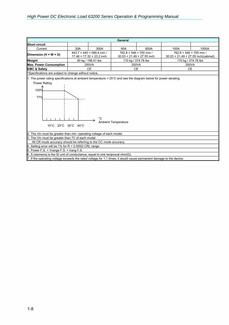
1. The power rating specifications at ambient temperature = 25°C and see the diagram below for power derating. Power Rating
100%
77% °C Ambient Temperature 10°C 20°C 30°C 40°C
2. The Vin must be greater than min. operating voltage of each model. 3. The Vin must be greater than 7V of each model. All CR mode accuracy should be referring to the CC mode accuracy. 4. Setting error will be 1% for R < 0.005Ω CRL range. 5. Power F.S. = Vrange F.S. × Irang F.S. 6. S (siemens) is the SI unit of conductance, equal to one reciprocal ohm(Ω). 7. If the operating voltage exceeds the rated voltage for 1.1 times, it would cause permanent damage to the device.

General Information
1-5
Model 63204 63205 63206 Power*1 520W 5200W 650W 6500W 1040W 10400W Current 0-10A 0-100A 0-18A 0-180A 0-60A 0-600A Voltage 0-500V*8 0-80V 0-80V
1.25V @ 5A 1.25V @ 50A 0.5V @ 9A 0.5V @ 90A 0.5V @ 30A 0.5V @ 300AMin. operating voltage 2.5V @ 10A 2.5V @ 100A 1V @ 18A 1V @ 180A 1V @ 60A 1V @ 600A
Constant Current mode Range 0-10A 0-100A 0-18A 0-180A 0-60A 0-600A Resolution 2.8mA 28mA 5.2mA 52mA 21mA 170mA Accuracy 0.1%+0.1%FS 0.2%+0.1%FS 0.1%+0.2%FS 0.1%+0.2%FS 0.1%+0.2%FS 0.1%+0.2%FSConstant Resistance mode Range 0.125-500Ω 5-20000Ω 0.008-32Ω 0.4-1600Ω 0.0025-10Ω 0.125-500Ω Resolution*6 2.3mS 57.56µS 35mS 0.7mS 112.5mS 2.25mS Accuracy*2 0.0046S+0.35% 0.08S+0.1% 0.07S+0.35% 0.75S+0.1% 0.225S+0.35%*4 1.2S+0.1% Accuracy*3 (Vin>7V) 0.0046S+0.35% 115.51µS+0.35% 0.07S+0.35% 0.0014S+0.35% 0.225S+0.35% 0.0045S+0.35%Constant Voltage mode Range 2.5-125V 2.5-500V 1-16V 1-80V 1-16V 1-80V Resolution 31mV 125mV 4mV 20mV 4mV 20mV Accuracy 0.05%+0.1%FS 0.05%+0.1%FS 0.05%+0.1%FS 0.05%+0.1%FS 0.05%+0.1%FS 0.05%+0.1%FSConstant Power mode Range 1.25-520W 12.5-5200W 0.36-650W 3.6-6500W 1.2-1040W 12-10400W Resolution 6.25mW 62.5mW 4.6mW 46mW 22.5mW 225mW Accuracy 0.5%+0.5%FS 0.5%+0.5%FS 0.5%+0.5%FS 0.5%+0.5%FS 0.5%+0.5%FS 0.5%+0.5%FS
Dynamic mode Timing T1&T2 0.025-10ms 1ms-30s 0.025-10ms 1ms-30s 0.025-10ms 1ms-30s Resolution 1µs 1ms 1µs 1ms 1µs 1ms Accuracy 1µs+100ppm 1ms+100ppm 1µs+100ppm 1ms+100ppm 1µs+100ppm 1ms+100ppm Slew rate 1.6mA-0.4A/µs 16mA-4A/µs 3mA-0.75A/µs 30mA-7.5A/µs 12mA-3A/µs 100mA-25A/µs Resolution 1.6mA/µs 16mA/µs 3mA/µs 30mA/µs 12mA/µs 100mA/µs Min. Rise Time 24µs (Typical) 24µs (Typical) 20µs (Typical) Current Range 0-10A 0-100A 0-18A 0-180A 0-60A 0-600A Resolution 2.8mA 28mA 5.2mA 52mA 21mA 170mA Accuracy 0.4%FS 0.4%FS 0.4%FS
Measurement Voltage read back Range 0-125V 0-500V 0-16V 0-80V 0-16V 0-80V Resolution 5mV 17.1mV 0.6mV 2.6mV 0.6mV 2.6mV Accuracy 0.05%+0.05%FS 0.05%+0.05%FS 0.05%+0.05%FS Current read back Range 0-10A 0-100A 0-18A 0-180A 0-60A 0-600A Resolution 0.35mA 3.5mA 0.7mA 7mA 2.6mA 21mA Accuracy 0.1%+0.1%FS 0.1%+0.1%FS 0.1%+0.1%FS Power read back Range 0-520W 0-5200W 0-650W 0-6500W 0-1040W 0-10400W Accuracy*5 0.3%+0.3%FS 0.3%+0.3%FS 0.3%+0.3%FS

High Power DC Electronic Load 63200 Series Operation & Programming Manual
1-6
General
Short circuit Current 10A 100A 18A 180A 60A 600A
Dimension (H × W × D) 353 × 440 × 589.4 mm / 13.89 × 17.32 × 23.2 inch
310 × 440 × 589.4 mm / 12.2 × 17.32 × 23.2 inch
443.7 × 440 × 589.4 mm / 17.46 × 17.32 × 23.2 inch
Weight 62 kg / 136.68 lbs 62 kg / 136.68 lbs 90 kg / 198.41 lbs Max. Power Consumption 150VA 200VA 250VA EMC & Safety CE CE CE *Specifications are subject to change without notice.
1. The power rating specifications at ambient temperature = 25°C and see the diagram below for power derating. Power Rating
100%
77% °C Ambient Temperature 10°C 20°C 30°C 40°C
2. The Vin must be greater than min. operating voltage of each model. 3. The Vin must be greater than 7V of each model. All CR mode accuracy should be referring to the CC mode accuracy. 4. Setting error will be 1% for R < 0.005Ω CRL range. 5. Power F.S. = Vrange F.S. × Irang F.S. 6. S (siemens) is the SI unit of conductance, equal to one reciprocal ohm(Ω). 7. If the operating voltage exceeds the rated voltage for 1.1 times, it would cause permanent damage to the device. 8. 600V modification available.

General Information
1-7
Model 63207 63208 63209 Power*1 1040W 10400W 1560W 15600W 1560W 15600W Current 0-30A 0-300A 0-60A 0-600A 0-100A 0-1000A Voltage 0-80V 0-80V 0-80V
0.5V @ 15A 0.5V @ 150A 0.5V @ 30A 0.5V @ 300A 0.5V @ 50A 0.5V @ 500A Min. operating voltage 1V @ 30A 1V @ 300A 1V @ 60A 1V @ 600A 1V @ 100A 1V @ 1000A
Constant Current mode Range 0-30A 0-300A 0-60A 0-600A 0-100A 0-1000A Resolution*6 10.3mA 82mA 21mA 163mA 34.2mA 274mA Accuracy 0.1%+0.2%FS 0.1%+0.2%FS 0.1%+0.2%FS 0.1%+0.2%FS 0.1%+0.2%FS 0.1%+0.2%FS Constant Resistance mode Range 0.005-20Ω 0.25-1000Ω 0.0025-10Ω 0.125-500Ω 0.0015-6Ω 0.075-300Ω Resolution 55.7mS 1.1mS 110mS 2.22mS 186.5mS 3.73mS Accuracy*2 0.111S+0.35% 0.9S+0.1% 0.22S+0.35%*4 1.2S+0.1% 0.373S+0.35%*4 1.2S+0.1% Accuracy*3 (Vin>7V) 0.111S+0.35% 0.0022S+0.35% 0.22S+0.35% 0.0044S+0.35% 0.373S+0.35% 0.0075S+0.35%Constant Voltage mode Range 1-16V 1-80V 1-16V 1-80V 1-16V 1-80V Resolution 4mV 20mV 4mV 20mV 4mV 20mV Accuracy 0.05%+0.1%FS 0.05%+0.1%FS 0.05%+0.1%FS 0.05%+0.1%FS 0.05%+0.1%FS 0.05%+0.1%FSConstant Power mode Range 0.744-1040W 6-10400W 1.2-1560W 12-15600W 2.5-1560W 20-15600W Resolution 9.3mW 75mW 22.5mW 225mW 31.255mW 250mW Accuracy 0.5%+0.5%FS 0.5%+0.5%FS 0.5%+0.5%FS 0.5%+0.5%FS 0.5%+0.5%FS 0.5%+0.5%FS
Dynamic mode Timing T1&T2 0.025-10ms 1ms-30s 0.025-10ms 1ms-30s 0.025-10ms 1ms-30s Resolution 1µs 1ms 1µs 1ms 1µs 1ms Accuracy 1µs+100ppm 1ms+100ppm 1µs+100ppm 1ms+100ppm 1µs+100ppm 1ms+100ppm Slew rate 6mA-1.5A/µs 50mA-12.5A/µs 12mA-3A/µs 100mA-25A/µs 20mA-5A/µs 166mA-41.6A/µs Resolution 6mA/µs 50mA/µs 12mA/µs 100mA/µs 20mA/µs 166mA/µs Min. Rise Time 20µs (Typical) 20µs (Typical) 20µs (Typical) Current Range 0-30A 0-300A 0-60A 0-600A 0-100A 0-1000A Resolution 10.3mA 82mA 21mA 163mA 34.2mA 274mA Accuracy 0.4%FS 0.4%FS 0.4%FS
Measurement Voltage read back Range 0-16V 0-80V 0-16V 0-80V 0-16V 0-80V Resolution 0.6mV 2.6mV 0.6mV 2.6mV 0.6mV 2.6mV Accuracy 0.05%+0.05%FS 0.05%+0.05%FS 0.05%+0.05%FS Current read back Range 0-30A 0-300A 0-60A 0-600A 0-100A 0-1000A Resolution 1.3mA 11mA 2.7mA 21mA 4.5mA 36mA Accuracy 0.1%+0.1%FS 0.1%+0.1%FS 0.1%+0.1%FS Power read back Range 0-1040W 0-10400W 0-1560W 0-15600W 0-1560W 0-15600W Accuracy*5 0.3%+0.3%FS 0.3%+0.3%FS 0.3%+0.3%FS
High Power DC Electronic Load 63200 Series Operation & Programming Manual
1-8
General
Short circuit Current 30A 300A 60A 600A 100A 1000A
Dimension (H × W × D) 443.7 × 440 × 589.4 mm / 17.46 × 17.32 × 23.2 inch
762.8 × 546 × 700 mm / 30.03 × 21.49 × 27.55 inch
762.8 × 546 × 700 mm / 30.03 × 21.49 × 27.55 inch(cabinet)
Weight 90 kg / 198.41 lbs 170 kg / 374.78 lbs 170 kg / 374.78 lbs Max. Power Consumption 250VA 250VA 250VA EMC & Safety CE CE CE *Specifications are subject to change without notice.
1. The power rating specifications at ambient temperature = 25°C and see the diagram below for power derating. Power Rating
100%
77% °C Ambient Temperature 10°C 20°C 30°C 40°C
2. The Vin must be greater than min. operating voltage of each model. 3. The Vin must be greater than 7V of each model. All CR mode accuracy should be referring to the CC mode accuracy. 4. Setting error will be 1% for R < 0.005Ω CRL range. 5. Power F.S. = Vrange F.S. × Irang F.S. 6. S (siemens) is the SI unit of conductance, equal to one reciprocal ohm(Ω). 7. If the operating voltage exceeds the rated voltage for 1.1 times, it would cause permanent damage to the device.

General Information
1-9
Model 63210 Power*1 1450W 14500W Current 0-15A 0-150A Voltage 0-600V
1.5V @ 7.5A 1.5V @ 75A Min. operating voltage*8 3V @ 15A 3V @ 150A
Constant Current mode Range 0-15A 0-150A Resolution 4.9mA 39mA Accuracy 0.1%+0.1%FS 0.2%+0.1%FS
Constant Resistance mode Range 0.1-400Ω 5-20000Ω Resolution*7 3.21mS 80.1µS Accuracy*2 0.0128S+0.35% 0.092S+0.1% Accuracy*3 (Vin>10V) 0.0128S+0.35% 317.7μS+0.35% Min. operating current 1A 1A
Constant Voltage mode Range 3V-150V 3V-600V Resolution 40mV 162mV Accuracy 0.05%+0.1%FS 0.05%+0.1%FS
Constant Power mode Range 5-1450W 50-14500W Resolution 25mW 250mW Accuracy 0.5%+0.5%FS 0.5%+0.5%FS
Dynamic mode Timing T1&T2 0.025-10ms 1ms-30s Resolution 1µs 1ms Accuracy 1µs+100ppm 1ms+100ppm Slew rate*9 3mA-0.75A/µs 25mA-6A/µs
Resolution 3mA/µs 25mA/µs Min. Rise Time 150μs (Typical)
Min. Operating Voltage @ Dynamic mode 3V
Current Range 0-15A 0-150A Resolution 4.9mA 39mA Accuracy 0.4%FS
Measurement Voltage read back Range 0-150V 0-600V Resolution 5.1mV 21mV Accuracy 0.05%+0.05%FS Current read back Range 0-15A 0-150A Resolution 0.64mA 5.1mA Accuracy 0.1%+0.1%FS Power read back Range 0-1450W 0-14500W Accuracy*5 0.3%+0.3%FS

High Power DC Electronic Load 63200 Series Operation & Programming Manual
1-10
General
Short circuit Current 15A 150A
Dimension (H × W × D) 762.8 × 546 × 700 mm / 30.03 × 21.49 × 27.55 inch(cabinet)
Weight 170 kg / 374.78 lbs Max. Power Consumption 250VA EMC & Safety CE *Specifications are subject to change without notice.
1. The power rating specifications at ambient temperature = 25°C and see the diagram below for power derating.
Power Rating
100%
77% °C Ambient Temperature 10°C 20°C 30°C 40°C
2. For Vin greater than min. operating voltage and less than 10V. 3. For Vin greater than 10V. 4. Setting error will be 1% for R < 0.005Ω at CRL range. 5. Power F.S. = Vrange F.S. × Irange F.S. 6. If the operating voltage exceeds the rated voltage for 1.1 times, it would cause permanent
damage to the device. 7. S (Siemens) is the SI unit of conductance, equal to one reciprocal ohm(Ω). 8. To ensure full load current at CCH and CCL mode under low operating voltage, please set
the voltage measurement range as low range. 9. The minimum rise time of CC dynamic is 150μs for 600V 63210. If the minimum rise time
is shorter than 150μs, the current overshoot will be over 5% of full scale current.

General Information
1-11
1.5 Dimension Outline for 63200 Series Model 63201 and 63202
Model 63203 and 63204

High Power DC Electronic Load 63200 Series Operation & Programming Manual
1-12
Model 63205
Model 63206 and 63207
General Information
1-13
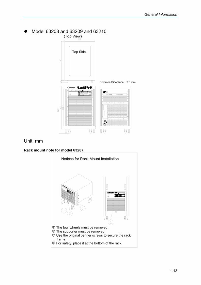
Model 63208 and 63209 and 63210 (Top View)
Unit: mm Rack mount note for model 63207:
Common Difference ± 2.0 mm
Top Side
Notices for Rack Mount Installation
1 The four wheels must be removed.2 The supporter must be removed. 3 Use the original banner screws to secure the rack
frame. 4 For safety, place it at the bottom of the rack.

High Power DC Electronic Load 63200 Series Operation & Programming Manual
1-14
Installing the 63200 Protective Cover: Step 1: Insert the cable into protective cover. Step 2: Socket the Bakelite into the positive/negative copper plate until it touches the
chassis and then secure the M6x20L screw and M6 screw nut to block the Bakelite.
Step 3: Place a washer on the M6x20L screw and let it go through the positive/negative copper plate. Connect the two cables with an insulator to secure the cables on the positive/negative copper plate.
Step 4: Cover the positive/negative copper plate with protective cover on the rear panel. Step 5: Use the attached M6x10L screw to secure the protective cover. Step 6: Complete installation.
Installation
2-1
2. Installation
2.1 Introduction This chapter describes how to install the 63200 series Load as well as a turn-on check procedure and application considerations.
2.2 Inspection As soon as the instrument is unpacked, inspect any damage that might have occurred in shipping. Keep all packing materials in case that the instrument has to be returned. If any damage is found, please file a claim to the carrier immediately. Do not return the instrument to Chroma without prior approval. In addition to this manual, be sure that the following items are also received – a power cord, this manual, a pair of load terminal screws kit and a V-sense cable. Please ensure the following items are received correctly. Model Item Name Qty
Operation Manual (CD) 1 copy Power Cord 1 pc. Electronic Load Terminal Screw Kit 1 set V-sense Cable (red and black one for each) 2 pc. RS-485 Parallel Cable 1 pc. Ear Rack 2 pcs.
63201 63202 63203 63204 63205 63206 63207 Handle 2 pcs.
Model Item Name Qty
63208 Operation Manual (CD) 1 copy Power Cord 1 pc. Electronic Load Terminal Screw Kit 1 set V-sense Cable (red and black one for each) 2 pc. RS-485 Parallel Cable 1 pc.
2.3 Installing The Electric Loads can operate well within the temperature range from 0 ºC to 40 ºC. However, you must install the Electric Load in an area that has enough space around the unit for adequate air flowing through and escaping from the back.

High Power DC Electronic Load 63200 Series Operation & Programming Manual
2-2
2.3.1 Changing Line Voltage The Electronic Load can operate with a 115/230 Vac input as indicated on the left hand side of the unit (facing the unit). If the factory set voltage does not correspond to your nominal line voltage, set the switch to the correct line voltage as shown in Figure 2-1 before plugging in the power cord and turning on the power.
Line fuses do not need to be changed when the line voltage is changed. The line fuses will protect the Electronic Load for incorrect voltage setting.
Figure 2-1 Line Voltage Switch
2.3.2 Turn-On Self-Test Check the following before turning on the Load. 1. The unit has been set to the correct line voltage by factory. Refer to the line voltage
indicated on the left hand side of the panel. 2. The power cord is connected to the AC input socket.
WARNING The power supplies a chassis ground through a third connector. Be sure that your outlet is of three-conductor type with the correct pin connected to ground.
Turn on the Load by the power switch on the front panel and observe the display. Immediately after turning on, the Electronic Load executes a self-test to check the RS-232C, GPIB interface board and the system. The LCD displays
FRONT PANEL TESTING [ RS232 ] PASS
FRONT PANEL TESTING CHECKSUM PASS
GPIB ADDRESS X
Installation
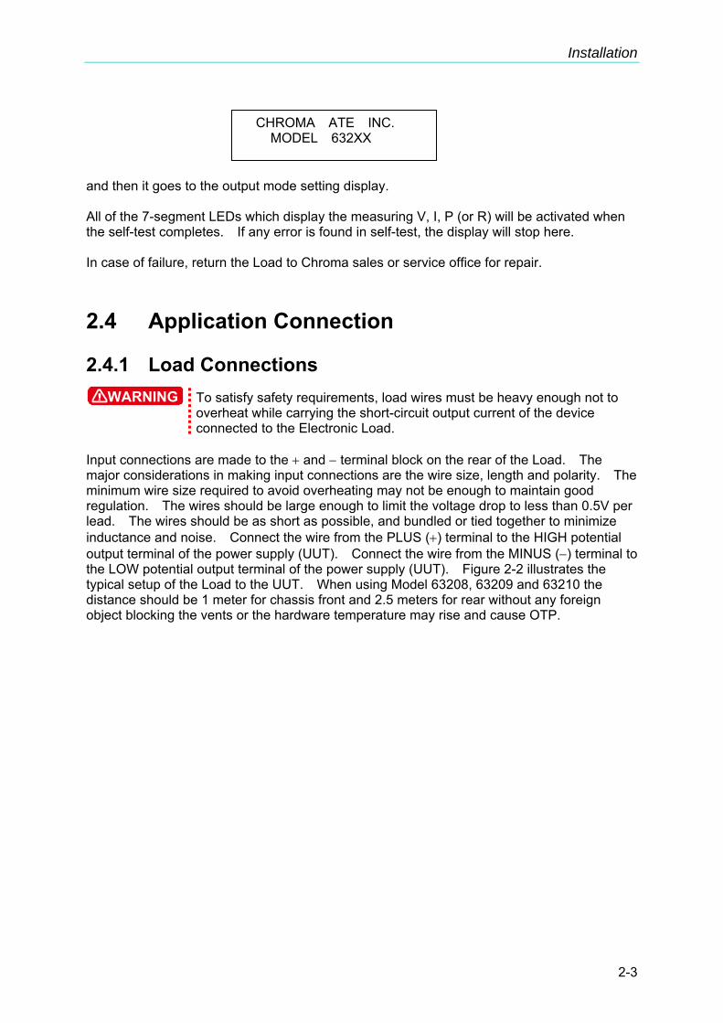
2-3
and then it goes to the output mode setting display. All of the 7-segment LEDs which display the measuring V, I, P (or R) will be activated when the self-test completes. If any error is found in self-test, the display will stop here. In case of failure, return the Load to Chroma sales or service office for repair.
2.4 Application Connection
2.4.1 Load Connections WARNING To satisfy safety requirements, load wires must be heavy enough not to
overheat while carrying the short-circuit output current of the device connected to the Electronic Load.
Input connections are made to the + and − terminal block on the rear of the Load. The major considerations in making input connections are the wire size, length and polarity. The minimum wire size required to avoid overheating may not be enough to maintain good regulation. The wires should be large enough to limit the voltage drop to less than 0.5V per lead. The wires should be as short as possible, and bundled or tied together to minimize inductance and noise. Connect the wire from the PLUS (+) terminal to the HIGH potential output terminal of the power supply (UUT). Connect the wire from the MINUS (−) terminal to the LOW potential output terminal of the power supply (UUT). Figure 2-2 illustrates the typical setup of the Load to the UUT. When using Model 63208, 63209 and 63210 the distance should be 1 meter for chassis front and 2.5 meters for rear without any foreign object blocking the vents or the hardware temperature may rise and cause OTP.
CHROMA ATE INC. MODEL 632XX
High Power DC Electronic Load 63200 Series Operation & Programming Manual
2-4
+_UUT
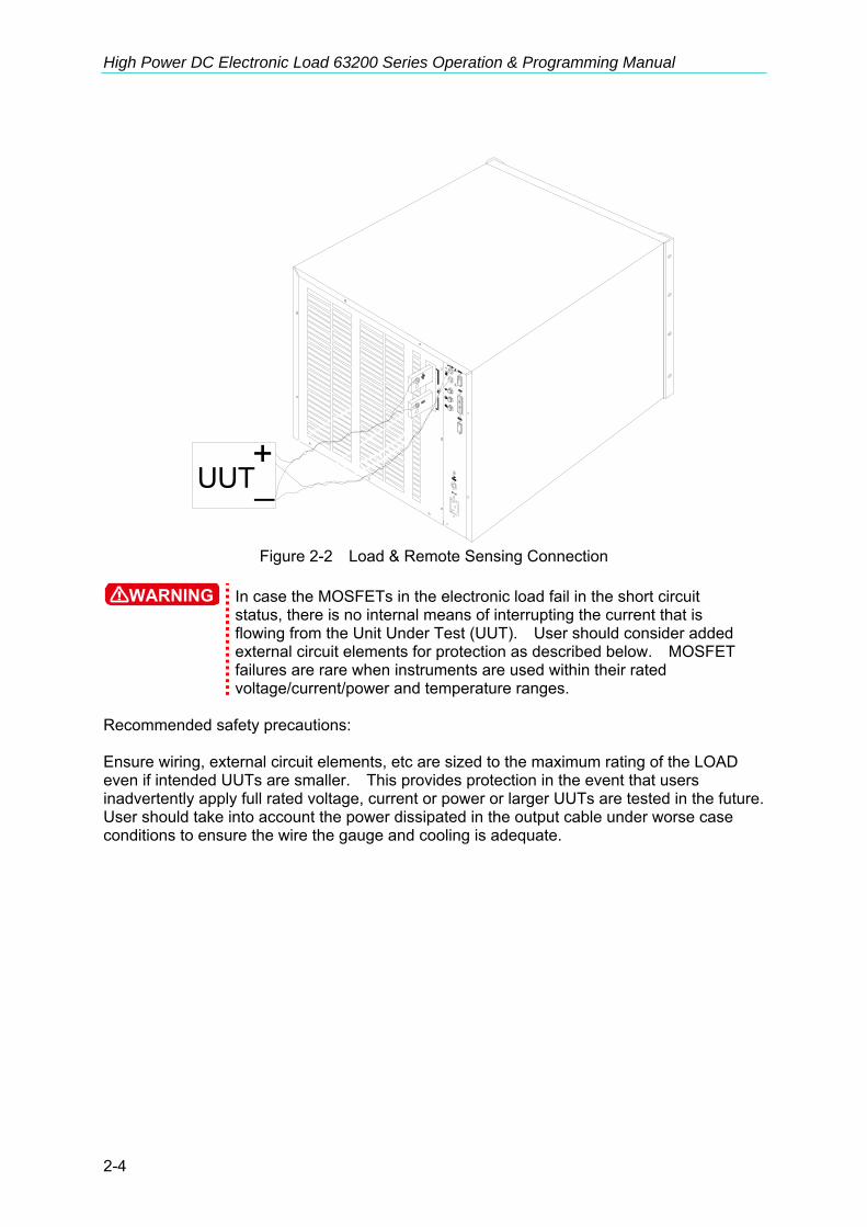
Figure 2-2 Load & Remote Sensing Connection
WARNING In case the MOSFETs in the electronic load fail in the short circuit
status, there is no internal means of interrupting the current that is flowing from the Unit Under Test (UUT). User should consider added external circuit elements for protection as described below. MOSFET failures are rare when instruments are used within their rated voltage/current/power and temperature ranges.
Recommended safety precautions: Ensure wiring, external circuit elements, etc are sized to the maximum rating of the LOAD even if intended UUTs are smaller. This provides protection in the event that users inadvertently apply full rated voltage, current or power or larger UUTs are tested in the future. User should take into account the power dissipated in the output cable under worse case conditions to ensure the wire the gauge and cooling is adequate.

Installation
2-5
Ensure the load always receives adequate ambient cooling air at all times and air filters, ducks, etc are maintained regularly. If loads are used with a cabinet, precautions should be taken to minimize heating within the cabinet. If the UUT may be damaged or an unsafe condition may occur in the event of a load short circuit (e.g. certain types of batteries), or if there is no means of de-energizing the UUT in the event of a load failure, user may consider including a suitably rated circuit breaker, fuse or other means of disconnecting the load from the UUT under emergency conditions. Note If there are any questions regarding safe operation of the equipment or adding
external protection circuits, please contact Chroma’s service personnel.
2.4.2 Remote Sensing Connections There are two sensing points for the Electronic Load. One is measurement at Load terminal, and another is measurement at Vsense. The Load will automatically switch to Vsense when Vsense terminals are connected to UUT, otherwise it will measure at Load terminals. Remote sensing compensates for voltage drop in applications that require long lead lengths. It is useful when the load is operating in CV or CR mode, or when it needs precise measurement. Figure 2-2 also illustrates a typical setup for remote sensing operation.
The potential of V-sense red connector must be higher than that of V-sense black connector.
2.4.3 Parallel Connections 63200 series Loads can be paralleled to increase power dissipation. The Loads can be directly paralleled in CC mode for static or dynamic operation while in CR and CP modes the Loads can be paralleled for static operation only. It is not suggested to parallel Loads in CV mode. The Loads is linked via RS-485 cable to RS485 port (see 2.4.4 RS-485 Parallel Connection Diagram). RS485 address represents the ID of each Load in the parallel group as the figure shown below. It enables the MASTER controller to connect to the Slave models correctly via the settings of RS485 ADDRESS and control the parallel load. There is only one Master in the parallel group, the rest are slaves. For 63200 Series, it can parallel up to 6 models and these Electronic Loads can be operated simultaneously via Master in static or dynamic mode. There are two operation modes in this parallel function: The first is MASTER mode. The master gets the total setting commands from the remote control or front panel and then informs the slaves what setting current they should do according to their model. (The slave model has to be ready first.) So the only one needs to programmed is the master.
RS485 ADDRESS 3

High Power DC Electronic Load 63200 Series Operation & Programming Manual
2-6
The second is MASTER SYNC mode. Each Load gets the current setting from its own remote control or front panel, the master controls the loads H/W synchronization action so that all loads can be operated with same action at the same time no matter in static or dynamic mode.
2.4.4 RS-485 Parallel Connection Diagram
2.4.4.1 Pin Assignment
Installation
2-7
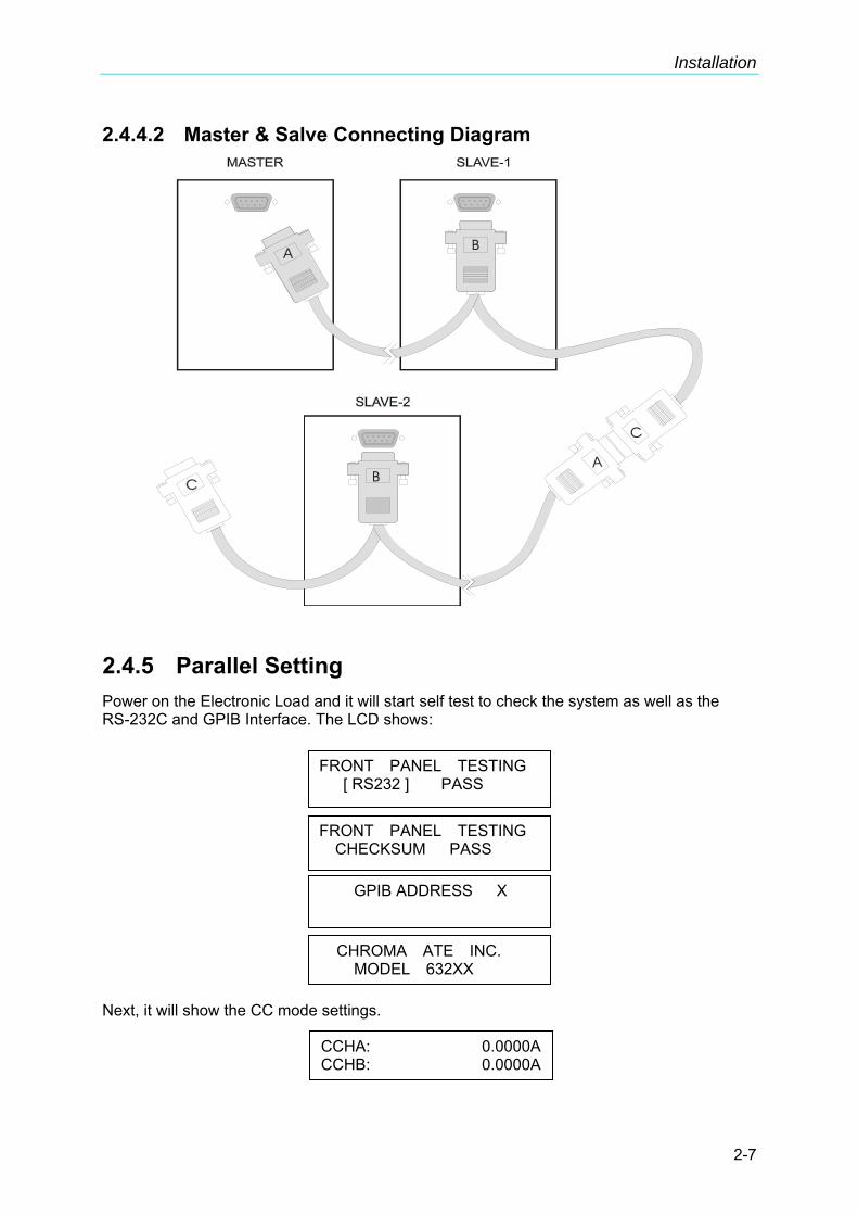
2.4.4.2 Master & Salve Connecting Diagram
2.4.5 Parallel Setting Power on the Electronic Load and it will start self test to check the system as well as the RS-232C and GPIB Interface. The LCD shows: Next, it will show the CC mode settings.
FRONT PANEL TESTING [ RS232 ] PASS
FRONT PANEL TESTING CHECKSUM PASS
GPIB ADDRESS X
CHROMA ATE INC. MODEL 632XX
CCHA: 0.0000ACCHB: 0.0000A

High Power DC Electronic Load 63200 Series Operation & Programming Manual
2-8
Press SYS to set the RS485 address of Slave so that it can be followed when setting the attribute of Master.
First it will prompt the default GPIB address. Next, press ↓→ to RS485 ADDRESS setting mode. The setting of RS485 ADDRESS maps to the slave number, for instance if RS485 ADDRESS = 2, the salve number is SLAVE 2. Press 1, ENTER to set the RS485 ADDRESS to 1.
When the setting is done, it will show several RS-232 parameter setting modes (Note 2). Press ↓→ to skip these modes until PARALLEL setting mode appears. (Note1): Set the Electronic Load to slave and press 2, ENTER: When the slave setting is done, it will prompt SYS setting automatically as shown below: Set the Master as follows: Connect the A port of RS485 cable to the selected Master. The start screen is same as the CC mode settings. Press SYS to enter into system setting mode. Since the Master setting is not related to RS485 ADDRESS, press ↓→ directly to go to PARALLEL setting screen.
GPIB ADDRESS X
RS485 ADDRESS 1
PARALLEL = NONE PRESS 0 → 3 TO SELECT
SLAVE1 OFFLINE
PARALLEL = SLAVE PRESS 0 → 3 TO SELECT
CCHA: 0.0000ACCHB: 0.0000A
PARALLEL = NONE PRESS 0 → 3 TO SELECT
Installation
2-9
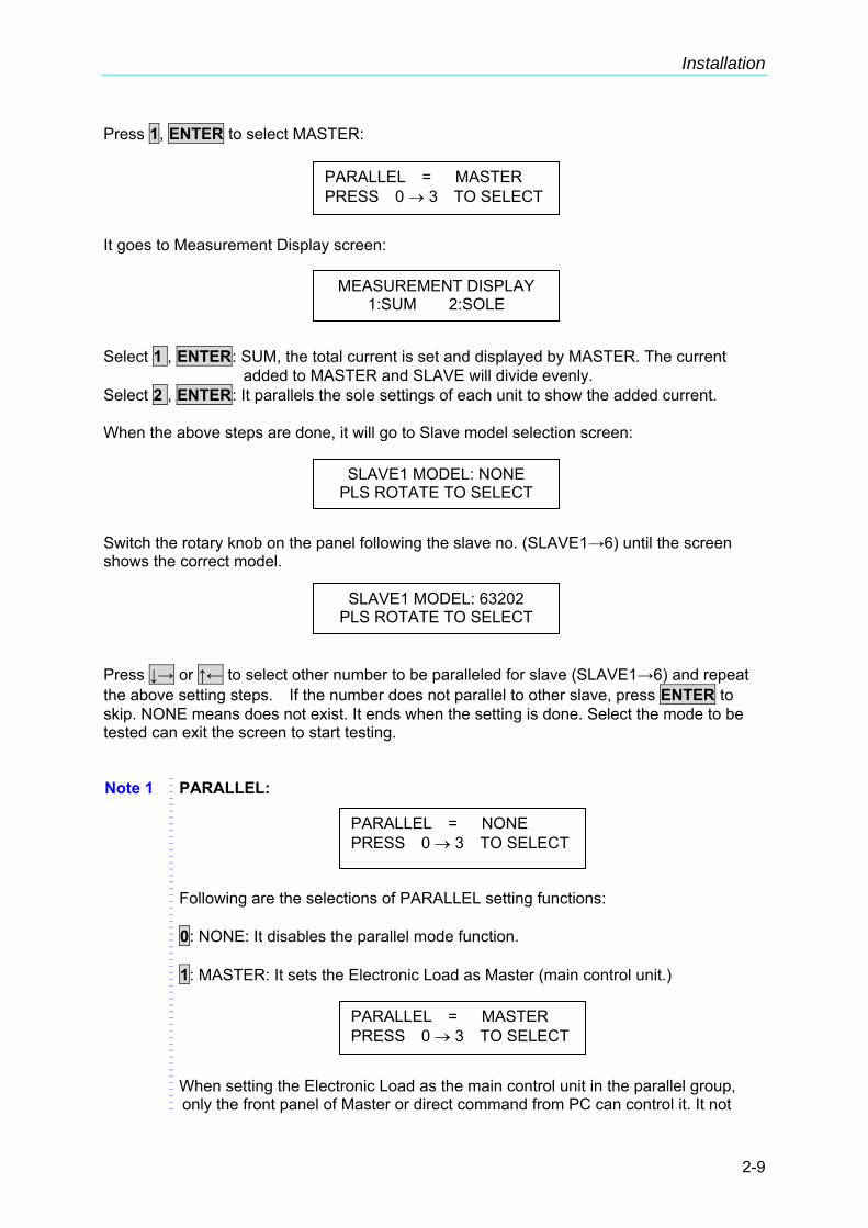
Press 1, ENTER to select MASTER: It goes to Measurement Display screen: Select 1 , ENTER: SUM, the total current is set and displayed by MASTER. The current
added to MASTER and SLAVE will divide evenly. Select 2 , ENTER: It parallels the sole settings of each unit to show the added current. When the above steps are done, it will go to Slave model selection screen: Switch the rotary knob on the panel following the slave no. (SLAVE1→6) until the screen shows the correct model.
Press ↓→ or ↑← to select other number to be paralleled for slave (SLAVE1→6) and repeat the above setting steps. If the number does not parallel to other slave, press ENTER to skip. NONE means does not exist. It ends when the setting is done. Select the mode to be tested can exit the screen to start testing. Note 1 PARALLEL:
Following are the selections of PARALLEL setting functions: 0: NONE: It disables the parallel mode function. 1: MASTER: It sets the Electronic Load as Master (main control unit.) When setting the Electronic Load as the main control unit in the parallel group, only the front panel of Master or direct command from PC can control it. It not
MEASUREMENT DISPLAY 1:SUM 2:SOLE
SLAVE1 MODEL: NONE PLS ROTATE TO SELECT
SLAVE1 MODEL: 63202 PLS ROTATE TO SELECT
PARALLEL = MASTER PRESS 0 → 3 TO SELECT
PARALLEL = NONE PRESS 0 → 3 TO SELECT
PARALLEL = MASTER PRESS 0 → 3 TO SELECT

High Power DC Electronic Load 63200 Series Operation & Programming Manual
2-10
only can operate simultaneously but also can inform Slave the current for loading. 2: SLAVE: It sets the Electronic Load to Slave. 3: MASTER SYN: It performs parallel synchronization only. All Master, Slave
loadings need to be inputted separately but the control movement and usage mode will be determined by the front panel on MASTER or PC input for synchronization.
2.5 Remote Control Connection The remote operation of Load can be done through GPIB, RS-232C or remote controller. These connectors on the rear panel connect the Load to the controller or computer. The GPIB interface of the electronic load is standard. The remote controller is optional. The 63200 series Remote Controller can control the load via RS-232C port. Connect the Remote Controller to the Electronic Load before powering it on.
SLAVE1 OFFLINE
PARALLEL = MST SYNC PRESS 0 → 3 TO SELECT

Operation Overview
3-1
3. Operation Overview
3.1 Introduction Chroma 63200 series electronic loads are suitable for design, manufacturing, testing and quality assurance. It contains a processor, GPIB and RS-232C connectors, front panel keypad, display, and power stage. Its built-in remote control function allows you to control, read back current, voltage and status. The Save/Recall feature allows you to save up to 100 files, 10 programs, and one default setting. All of them can be saved in load EEPROM for future use. The load contains four cooling fans. The fan speed increases or decreases automatically when the load power rises or falls. This feature reduces the overall noise level as the fans do not always run at the maximum speed. Each load can operate in constant current (CC), constant resistance (CR), constant voltage (CV), and constant power (CP) modes. If the application is larger than one of DC load can provide in power or current rating, the DC loads operation in parallel is a suggested way. However, it can be applied in CC mode, CP mode and CR mode.
3.2 Front Panel Description The front panel of the load includes a 20 × 2 characters LCD display, three segment LED, 9 led status indicators, and keypads. The LCD display will show which function is being performed when you use the keypads. One of the keys has two functions. Figure 3-1 shows the front panel of the loads.
Figure 3-1 Front Panel
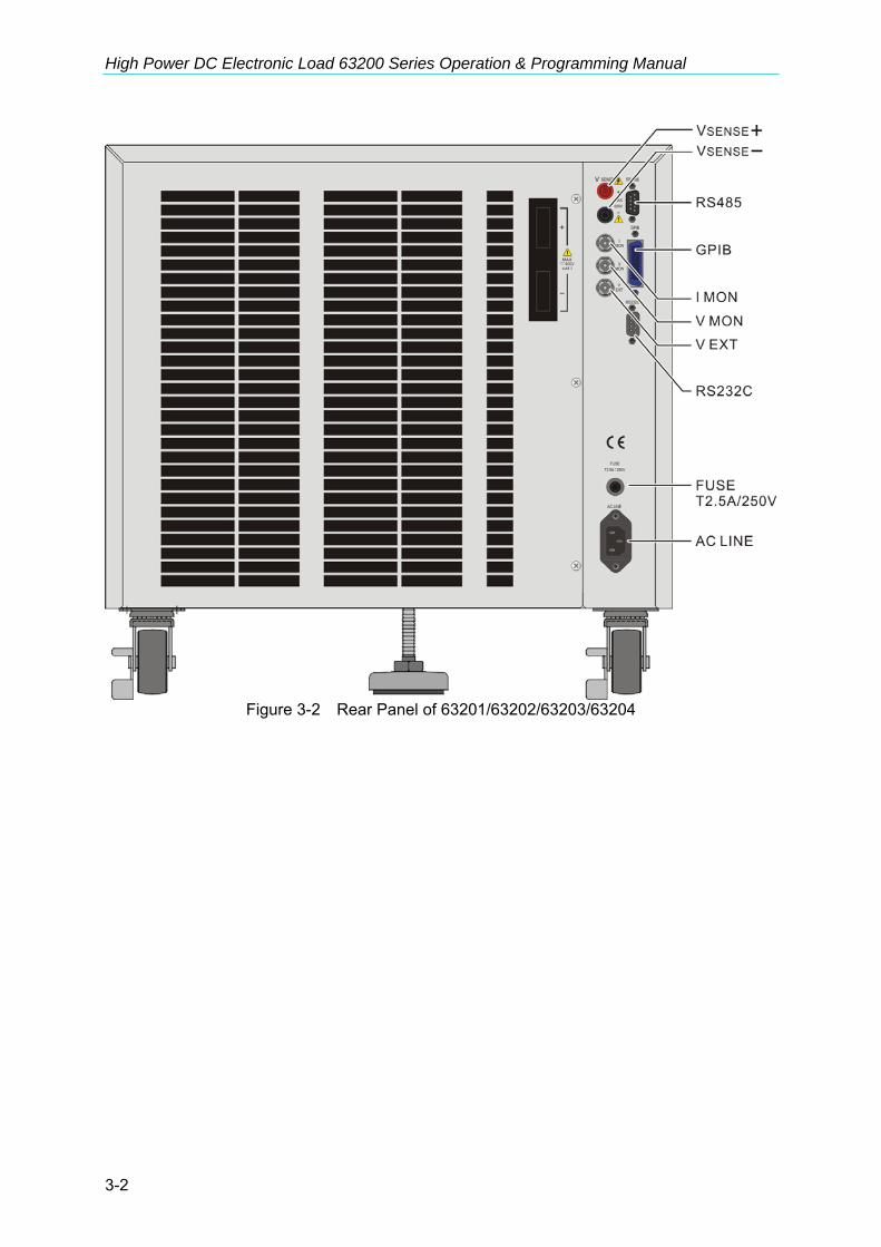
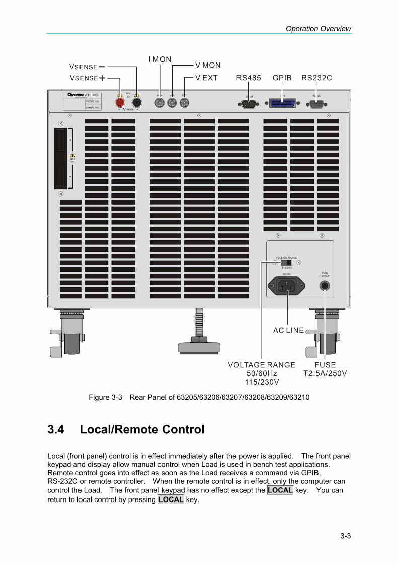
3.3 Rear Panel Description The Mainframe rear panel includes ports of RS-232C, RS485, GPIB, two remote sense, three BNC connectors, a pair of input terminals, an AC LINE socket, and a fuse holder. Figure 3-2 and Figure 3-3 shows the rear panel of Mainframe 63200.
High Power DC Electronic Load 63200 Series Operation & Programming Manual
3-2
Figure 3-2 Rear Panel of 63201/63202/63203/63204
Operation Overview
3-3
Figure 3-3 Rear Panel of 63205/63206/63207/63208/63209/63210
3.4 Local/Remote Control Local (front panel) control is in effect immediately after the power is applied. The front panel keypad and display allow manual control when Load is used in bench test applications. Remote control goes into effect as soon as the Load receives a command via GPIB, RS-232C or remote controller. When the remote control is in effect, only the computer can control the Load. The front panel keypad has no effect except the LOCAL key. You can return to local control by pressing LOCAL key.

High Power DC Electronic Load 63200 Series Operation & Programming Manual
3-4
Most of the functions that perform remotely can be done locally too at the Load front panel. Details of local operation are given in Chapter 4 Local Operation. Fundamentals of remote programming are described in the latter part of this manual.
3.5 Modes of Operation There are four modes of operation: Constant Current (CC), Constant Resistance (CR), Constant Voltage (CV), and Constant Power (CP). You can select the mode by pressing CC, CR, CV, or CP keys under the FUNCTION keypad. The parameters in current, resistance, voltage or power mode can be programmed easily when the mode is selected. All data set in CC/CR/CV/CP mode will be rescaled to fit the resolution of current/voltage levels or slew rate. In local mode any value can be set to the Load from the keypad. There is no upper and lower limit that would cause an error. The Load automatically selects data, which is rescaled from the programmed value, truncates and checks high, low boundary before fitting it into the memory. When the programmed data is over the boundary, the Load will set the maximum or minimum level for it. In remote mode the programmed value cannot be over boundary. An error will occur when data is over the maximum or minimum value.
3.5.1 Constant Current Mode
Figure 3-4 Constant Current Mode In CC mode, the Load will sink a current in accordance with the programmed value regardless of the input voltage. The CC mode can be set by CC key in the front panel. Press A/B key to select the current waveform in Static mode. Static function checks the stability of output voltage from a power supply. Press DYNA key to select the current waveform in Dynamic mode. This key is only valid under CC mode, and Dynamic function checks the transient response.
I current setting Load Current V Input Voltage
Operation Overview
3-5
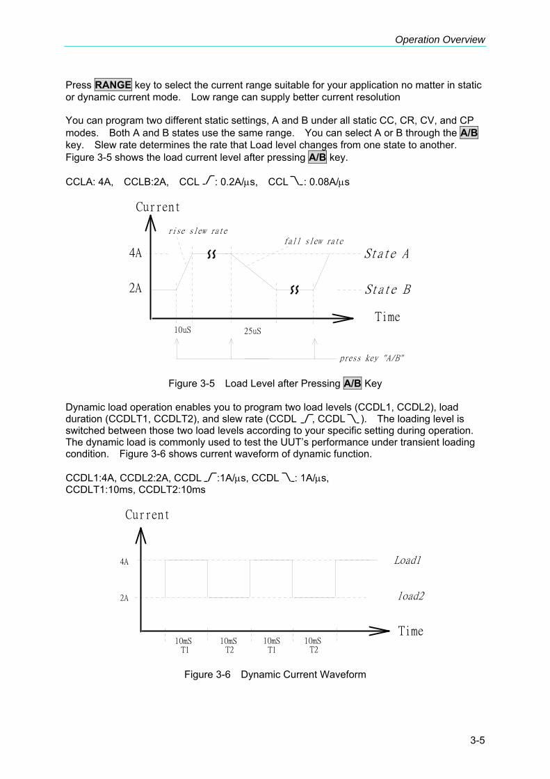
Press RANGE key to select the current range suitable for your application no matter in static or dynamic current mode. Low range can supply better current resolution You can program two different static settings, A and B under all static CC, CR, CV, and CP modes. Both A and B states use the same range. You can select A or B through the A/B key. Slew rate determines the rate that Load level changes from one state to another. Figure 3-5 shows the load current level after pressing A/B key. CCLA: 4A, CCLB:2A, CCL : 0.2A/μs, CCL : 0.08A/μs
Time
Current
rise slew ratefall slew rate
State A
State B
4A
2A
10uS 25uS
press key "A/B"
Figure 3-5 Load Level after Pressing A/B Key Dynamic load operation enables you to program two load levels (CCDL1, CCDL2), load duration (CCDLT1, CCDLT2), and slew rate (CCDL , CCDL ). The loading level is switched between those two load levels according to your specific setting during operation. The dynamic load is commonly used to test the UUT’s performance under transient loading condition. Figure 3-6 shows current waveform of dynamic function. CCDL1:4A, CCDL2:2A, CCDL :1A/μs, CCDL : 1A/μs, CCDLT1:10ms, CCDLT2:10ms
Time
Current
Load1
load2
10mS 10mS 10mS 10mS
4A
2A
T1 T2 T1 T2
Figure 3-6 Dynamic Current Waveform

High Power DC Electronic Load 63200 Series Operation & Programming Manual
3-6
Slew Rate (Rise, Fall A/μs) Slew rate determines the rate at which the current input of changes to a newly programmed value. There are two slew rate values, which are rise rate and fall rate. CC mode voltage specification setting The Load can do GO/NG test by pressing the GO/NG key under loading condition. It will check if the measured data is within the specification that set at the end of each mode setting. We can select are two types of parameters, percent or value, under the configure setting. This operation will be described in detail in section 4.2.4 Setting the Specification.
3.5.2 Constant Resistance Mode
Figure 3-7 Constant Resistance Mode In CR mode, the Load will sink a current linearly proportional to the input voltage in accordance with the programmed resistance. There is a double pole RC filter of input voltage, so high frequency parts will be removed. The load sink current of CR mode is proportioned to the input voltage through a double pole RC filter. To prevent the load current change caused by the input voltage variation, the power source impedance should be as low as possible, and remote sensing cable must be used to sense load input voltage when high sink current (low setting resistance) is programmed. Resistance can be programmed in either of low range or high range by the RANGE key. The low range is used for input voltage in low voltage range while the high range is for the input voltage over low voltage range. The current range of CR mode is high range. There are two resistance levels (A or B) for CR function as static CC mode. Both A and B states use the same range. You can select CRLA or CRLB using A/B key. Slew rate determines the rate that the load level changes from one state to another.
V Input Voltage Slope (R setting) I Load Current

Operation Overview
3-7
3.5.3 Constant Voltage Mode
Figure 3-8 Constant Voltage Mode In CV mode, the current will be loaded by the programmed value to control the voltage source. There are two response speeds of CV modes: fast and slow. The fast/slow respond speed is the slew rate of current change. Voltage can be programmed in either of low range or high range by the RANGE key. The low range is used for input voltage in low voltage range while the high range is for the input voltage over low voltage range. There are two voltage levels (A or B) for CV function. You can select CVHA or CVHB using A/B key.
3.5.4 Constant Power Mode
Figure 3-9 Constant Power Mode In CP mode, the current will be loaded by the programmed power. This mode is operated under the F/W calculation. That is, take the measured V data, divide the Power setting and get the I setting value. High frequency parts will be removed as there is a lower pass filter for the measuring data.
I Load Power setting Current P = V * I V Input Voltage
V Voltage setting Input Voltage I Load Current

High Power DC Electronic Load 63200 Series Operation & Programming Manual
3-8
Power can be programmed in either of low range or high range by the RANGE key. The low power range is operated under low current range mode while the high power range is under high current range mode. There are two power levels (A or B) for CP function as other modes. Both A and B states use the same range. You can select CPLA or CPLB using A/B key. Slew rate determines the rate that the load level changes from one state to another.
3.5.5 Load Surge Capability Chroma’s 63200 Series DC Loads provide a unique load surge simulation capability, which allows users to overdrive the loads up to 2.7 times their rated power for short periods. This feature is ideal when the average power require by the UUT is low compared to short-term peak power demands. Plasma Display Panel (PDPs) testing is one typical application, others include battery 3C discharge, breaker & fuse over rating (300% to 1000%) tests, car engine startup simulation and DC motor startup simulation. The amount of surge loading available using the 63200 loads is related to the initial loading conditions. Figure 3-10 and Figure 3-11 show the relationship of initial state (Load_Low under Dynamic mode) and the maximum acceptable overdrive power. Under this operation, the load will display an Over Power Protection Alarm (OPP) and will disable the load current if the user violates the maximum load surge capability showed in the figures below.
Figure 3-10 Load Surge Capability (Static Mode)

Operation Overview
3-9
Figure 3-11 Load Surge Capability (Dynamic Mode)
Note 1. The Initial state under Static Mode should last at least 1 second.
2. This load surge capability will be regulated by the temperature de-rating characteristics. (Refer to Note 1 in Specifications)
3. Examples below assume the use of the Model 63201 load with a continuous rating of 2600W/300A/1-80VDC.
Example 1: STATIC LOADING The Model 63201 can be overdriven to approximately 5200W (200% of its rated continuous power rating) for 0.06 seconds when the starting power is 650W (25% of its rated power). This is represented by DOT on the blue curve in Figure 3-10. Example 2: DYNAMIC LOADING The Model 63201 is capable of a zero – to- 6500W (250%) pulse at a duty cycle of 5%. This is represented by the DOT on the purple curve in Figure 3-11.
3.5.6 Timer Function for Battery Discharge Testing The 63200 Loads include unique timing & measurement function allowing for precision time settings and measurements in the range of 1s to 99999s. This feature allows users to set a final voltage & timeout value for battery discharge testing and similar applications. For example, Figure 3-12 below shows that the 63200’s internal timer can be initiated automatically when the battery voltage falls below a preset value. The timer will continue counting until the second preset voltage value is reached.

High Power DC Electronic Load 63200 Series Operation & Programming Manual
3-10
Figure 3-12
3.6 Measurements The Load measures current, voltage, and power of the UUT and resistance of the Loading. The sampling rate is about 8 ms. Voltage and current measurements are performed with a 15-bit resolution of full-scale ratings. There are three sets of 7-segment LEDs for the measuring data. One is for voltage, another is for current, and the other is for Power or Resistance that you can select under the configuration setting. The OHMS led will be on when you select the resistance measurement.
3.7 Slew Rate & Minimum Transient Time Slew rate is defined as the change in current over time. A programmable slew rate allows a controlled transition from one load setting to another to minimize induced voltage drops on inductive power wiring, or to control induced transients on a test device. If the transient from one setting to another is large, the actual transient time can be calculated by dividing the current transition by the slew rate. The actual transition time is defined as the time required for the change of input from 10% to 90% or from 90% to 10% of the programmed excursion. If the transition from one setting to another is small, the small signal bandwidth of Load will limit the minimum transition time for all programmable slew rates. Because of the limit, the actual transition time is longer than the expected time based on the slew rate. Therefore, both minimum transition time and slew rate must be considered in the determination of actual transition time. The minimum transition time is from 24 μs to 6 ms depending on the slew rate setting.

Operation Overview
3-11
3.8 Start/Stop Current Loading To simulate the transient characteristics of load to UUT, the critical problems are when and how the Load starts current loading to UUT. You may set the conducting voltage Von to solve the problems. The Load will start or stop sinking current when the UUT output voltage reaches the Von voltage. You can start current loading when the load is ON, and the input voltage is over Von voltage, but stop loading when the load is OFF, or the input voltage is below Von voltage. See Figure 3-13 and Figure 3-14 for start and stop current loading. There are two operation modes for Von control, latch and non-latch. Latch means that when voltage is over Von voltage, Load will start current loading continuously in spite of the input voltage drop is below Von voltage. Non-latch means that when the input voltage is below Von voltage, the Load will stop current loading. The Von voltage and operation mode are set in configuration.
Figure 3-13 Start Current Loading (Von Non-Latch)

High Power DC Electronic Load 63200 Series Operation & Programming Manual
3-12
Figure 3-14 Stop Current Loading (Von Non-Latch)
3.9 Short On/Off The Load can simulate a short circuit at input by setting it on with full-scale current. The short circuit can be on/off from the front panel or via remote control. There are two operations for SHORT key on the front panel. One is toggled on/off, and the other is controlled by key. They are selected in configuration. The SHORT key will be enabled only when the Load is ON. Toggled on/off means pressing SHORT once to enable short circuit, and again to disable it. Control by Key means pressing SHORT and holding it to enable short circuit, and releasing it to return to normal operation. The actual value of electronic short depends on the mode and range that are active when the short is turned on. Its basic limit is the maximum power range the Load can supply. In CC mode it is equivalent to the programming of full-scale current. In CR mode it is equivalent to the programming of the minimum resistance for the present resistance range. In CV mode it is equivalent to the programming of zero voltage. In CP mode it is equivalent to the programming of the maximum power for the present power range. Turning on the short circuit does not affect the programmed setting, and Load input will return to the previous programmed values when the short circuit is turned off. Please be noted that turning on the short circuit may cause loading too much current to trig protection circuit to turn off the Load.
The 63200 series have a TTL signal from RS-485 pin 6 for your application to control the external short relay. TTL indicates high/low when the short key is set on/off.

Operation Overview
3-13
3.10 Load On/Off A module’s input can be toggled on/off through the blue LOAD ON/OFF key on the front panel, or the remote control. The on/off change for input is done according to the slew rate. Turning off the load does not affect the programmed setting. The load will return to the previous programmed values when the Load is turned on again.
3.11 Protection Features The load includes the protection features: Over power, Over temperature, Fan fail, and Abnormal Alarms for Reverse Voltage and Over Voltage. The appropriate bits in the Load status registers are set when any of the protection features or alarm listed above is active. The Load’s buzzer will beep to inform you till protection or alarm status is reset. When any of the protection or alarm occurs, the Load input will turn off.
Over voltage The over voltage alarm circuit is set at a level slightly above the voltage range specified in the Load specification. The over voltage status register bit is set when the OV condition occurs and will remain set till it is reset. The Load will appear OVP as below when over voltage alarm occurs.
Over current When Load is operating in CR or CV mode, it is possible to attempt loading current more than it is rated for. The limit level of current is set at a level slightly above the current of the Load. The over current status register bit is set when the OC condition occurs, and will remain set till it is reset. The Load will appear as below when over current protection occurs.
Over power The over power protection circuit is set at a level slightly above the power range specified in the Load specifications. The over power status register bit is set when the OP condition occurs, and will remain set till it is reset. The Load will appear as below when over power protection occurs. This protection will be activated also if the power exceeds the maximum surge load capability mentioned in section 3.5.5.
PROTECTION OCP
PROTECTION OPP
PROTECTION OVP

High Power DC Electronic Load 63200 Series Operation & Programming Manual
3-14
Over temperature The Load has an over temperature protection circuit, which will turn off the load if internal temperature exceeds the safe limit. The over temperature status register bit is set when the OT condition occurs, and will remain set till it is reset. Load will appear as below when over temperature protection occurs.
Reverse Voltage The Load can conduct a reverse current when the polarity of UUT connection is not correct. The maximum safe reverse current is same as the Load rated current. If the UUT reverse current is over the Load rated current, the Load may be damaged. If a reverse voltage condition is detected, you must turn off the power to UUT immediately and correct the connection. The reverse voltage status register bit is set when the RV condition occurs, and will remain set till it is reset. The Load will appear as below when reverse voltage alarm occurs.
FAN FAIL The Load has a fan fail protection circuit, which will turn off the load if any of the four fans is out of order. The fan fail status register bit is set when the condition occurs, and will remain set till it is reset. The Load will appear as below when fan fail protection occurs.
All of the protections or alarms will latch when they are tripped. When any protection or alarm occurs, the load will turn off the input, and beep till you remove the condition and reset the protection by pressing ENTER.
CAUTION To protect the Electronic Load from possible damage, the input voltage must not exceed the maximum input voltage rating specification. In addition, the Load + terminal potential must be more than the − terminal potential.
3.12 Save/Recall Setting The Electronic Load setting can be saved and recalled for various test setups use. This simplifies the repetitive programming for different things. The present setting of mode parameters (CC, CR, CV, CP), programs and power on status (DEFAULT) can be saved in EEPROM using the SAVE key. Later you can recall the settings from the specified file via RECALL key.
PROTECTION OTP
PROTECTION REV
FAN FAIL

Operation Overview
3-15
3.13 Program The program feature is very powerful. It allows you to simulate various test conditions. There are ten programs in the Electronic Load. Each program has ten sequences. The setting mapped to the program sequence in file is one on one. It means that program 1, sequence 1 maps to file 1, and program 3, sequence 4 maps to file 24. Please see section 4.2.2 and 4.2.3 for setting and running the program.
3.14 External Waveform Control The external dynamic test, operated in the CC mode, is similar to that under the Dynamic test, but the load level switching is controlled by the duty cycle of an External TTL signal. It works the same way as the dynamic test except that the Period control signals are not generated internally, but are inputted from V EXT. Connectors are on the rear panel. A 0-to-10V external signal corresponds to the 0-to-full scale input range, so that users should apply DC offset for the external signal in the range from 0 to 10V. For the configuration of external waveform control usage, refer to section 4.2.5 for details.
3.15 Voltage & Current Monitor The 63200 series have two isolated BNC connectors to monitor load voltage and current, the output signal from I MON and V MON. They are on the rear panel. A signal that maps to full scale will output from BNC connector. VMON is 0 ~ 10V maps to 0V ~ full-scale voltage and IMON is 0 ~ 10V maps to 0A ~ full-scale high range current. When in low range the IMON voltage of full-scale current for 63201~63205 is 10V and for 63206~63210 is 8V.
3.16 Von Protection The design of Von Protection is to protect the Von point from setting to 0V when in “LOAD ON”, or the overshoot that may occur when the voltage of UUT sudden drops to 0V and rises again in loading current state. The UUT and DC Load may be damaged if the UUT is connected. Von Protection is a default protection value for voltage. Though the DC Load is in loading mode under the voltage value, there is no real current loading action until the external voltage is larger than the default of Von Protection. Even if the Von point is set to 0V or the voltage is sudden dropped to 0V and raised again under loading current state, there will be no overshoot. This is to prevent the overshoot from damaging the UUT and the DC Load.
Note When high voltage models (63202,63204 and 63210) are in use, “CC, CP V RANGE SELECT” are in “HIGH” range and “Von Protection” is enabled, the maximum current may not be applied under minimum working voltage as the default voltage protection range of Von Protection is 0.5V~3.5V.

High Power DC Electronic Load 63200 Series Operation & Programming Manual
3-16
Example:
Figure 3-15 Connection of Power, UUT and DC Load
(1) When it is “LOAD ON”, VON POINT is set to 0V and Von Protection is disabled, the DC
LOAD will occur overshoot when the SW is turned off. It will damage the UUT and DC Load as Figure 3-16 shows.
Figure 3-16 When Von Point is set to 0V without Protection
UUT
DC Load
Vs
SW
Load Sink Current
UUT Output
I
V
t
t
Setting
Operation Overview
3-17
(2) When it is “LOAD ON”, VON POINT is set to 0V and Von Protection is enabled, the DC Load starts loading when the external voltage exceeds the protection voltage. No overshoot will occur under this condition as Figure 3-17 shows.
Figure 3-17 When Von Point is set to 0V with Protection (3) When it is “LOAD ON”, VON POINT is not set to 0V and Von Protection is enabled,
switch the SW to on after it was turned off for a period of time and then turn it off again. There will be no current loading when the power is lower than the default protection voltage, and once the SW is turned off and the power is larger than the default voltage, the loading state will regain as Figure 3-18 shows.
Figure 3-18 When Von Point is not set to 0V with Protection
UUT Output
Current
Load Sink
Von
Setting
Von protection t
t
V
I
Load Sink Current
UUT Output
I
V
t
t
Setting
Von

High Power DC Electronic Load 63200 Series Operation & Programming Manual
3-18
(4) When it is “LOAD ON”, VON POINT is not set to 0V and Von Protection is disabled, switch the SW to on after it was turned off for a period of time and then turn it off again. The current loading still goes on when there is no power, and overshoot may occur once the SW is turned off with any power input as Figure 3-19 shows. It may damage the UUT and the DC Load in this case.
Figure 3-19 Von Point is not set to 0V without Protection
3.17 CR Offset Error Compensation In CR mode the DC Load will follow the preprogrammed resistance to load the current to input voltage by linear ratio, and the change of input voltage causes the load current to change. CR compensation enables the input voltage of any kind to be accurate in CR mode. The resistance may generate the different offset errors, which could be very big due to various input voltage if there is no CR compensation. CR Compensation: (1) Advantage: The measurement in CR mode will be more accurate because of
compensation and the accuracy of 63200 Series is based on the compensated result. (2) Disadvantage: Controlling current is the mechanism of compensation and in the process
of continuous compensation; the current will fluctuate until reaching stable state to get accurate and stable current.
No CR Compensation: (1) Advantage: The loading current will not fluctuate due to the compensation mechanism. (2) Disadvantage: The reading in CR mode will be varied with voltage and same for the
accuracy.
3.18 External LOAD ON/OFF Control The External Load ON/OFF Control is to enable the DC Load ON/OFF function by external signals via RS-485 cable.
V
UUT Output
Current
Load Sink
Von
Setting
t
t
I
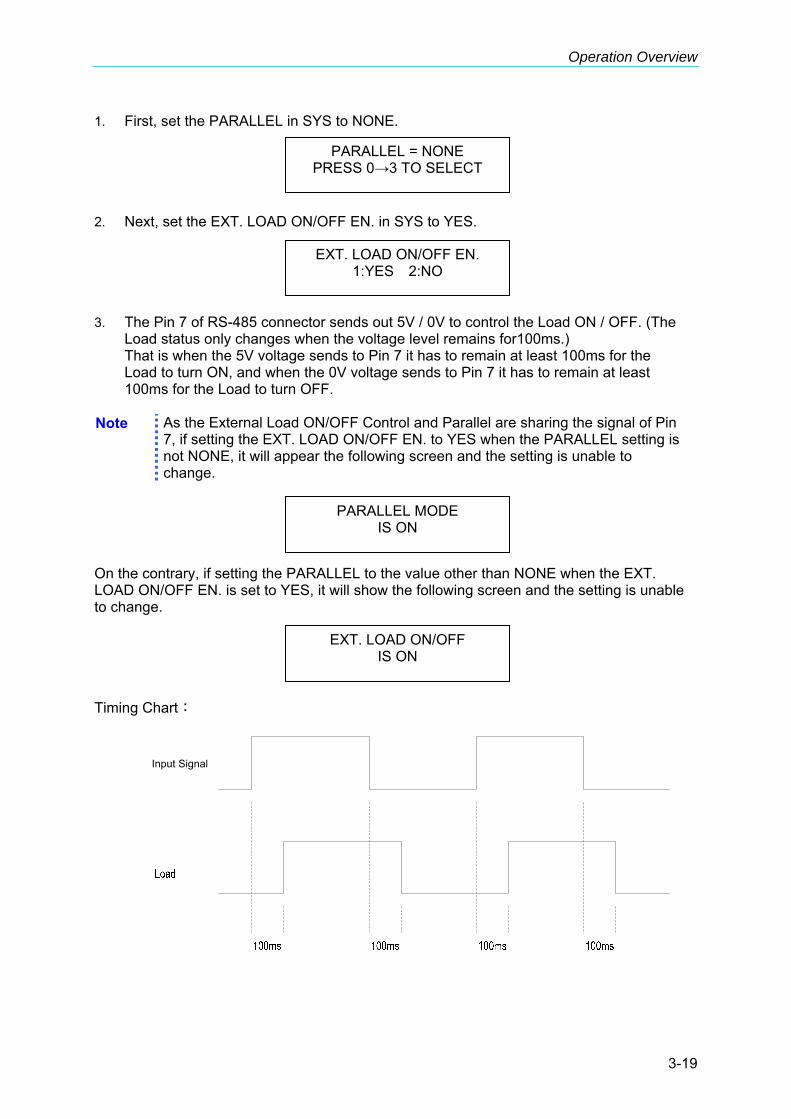
Operation Overview
3-19
1. First, set the PARALLEL in SYS to NONE. 2. Next, set the EXT. LOAD ON/OFF EN. in SYS to YES. 3. The Pin 7 of RS-485 connector sends out 5V / 0V to control the Load ON / OFF. (The
Load status only changes when the voltage level remains for100ms.) That is when the 5V voltage sends to Pin 7 it has to remain at least 100ms for the Load to turn ON, and when the 0V voltage sends to Pin 7 it has to remain at least 100ms for the Load to turn OFF. Note As the External Load ON/OFF Control and Parallel are sharing the signal of Pin
7, if setting the EXT. LOAD ON/OFF EN. to YES when the PARALLEL setting is not NONE, it will appear the following screen and the setting is unable to change.
On the contrary, if setting the PARALLEL to the value other than NONE when the EXT. LOAD ON/OFF EN. is set to YES, it will show the following screen and the setting is unable to change. Timing Chart:
EXT. LOAD ON/OFF EN. 1:YES 2:NO
PARALLEL = NONE PRESS 0→3 TO SELECT
PARALLEL MODE IS ON
EXT. LOAD ON/OFF IS ON
Input Signal


Local Operation
4-1
4. Local Operation
4.1 Introduction This chapter describes how to operate the electronic load from the local panel in details. The descriptions include panel control and indicators.
4.2 Local Operation In order to use the front panel keys to control the electronic load, local operation must be in effect. Immediately after the power is applied, local operation will be in effect. When local operation is in effect, you can use the display with keypad on the front panel to control the Load. The display can be used to view the programmed setting. The input voltage, current, power or resistance is displayed on the three 7-segment LEDs.
When you edit setting, the display will blink to let you know which setting is to be edited or has been selected.
In the remote state, the keys on the front panel have no effect. Only remote controller can program the Load. The 7-segment will show the present input voltage and current readings. The Load LCD display will show REMOTE message.
When setting the load level, the resolution of current, voltage, power, resistance and slew rate will be different from the entered values. The displayed value will remain as the one entered. But the output will be the actual value D/A programmed in the load. These parameters except resistance will be degraded to low values when entered.

High Power DC Electronic Load 63200 Series Operation & Programming Manual
4-2
VOLTS AMPS WATTS/OHMS
CP
CV
CR
CC
CURSOR
GO/NG
7
4
1
0 .2
5
8 9
6
3
EDIT
16V/80VMODEL 60A/600ADC ELECTRONIC LOAD 63203 4KW
4 5 61
3
2
Figure 4-1 Front Panel of the Load
1. Line switch Turn the ac power on/off. 2. LCD display Display setting information normally. 3. 7-segment LEDs Show the V, I, P, R measured data. 4. System keys
SYS To set the remote control status, ext. wave enable and Parallel function parameters.
RECALL To recall the saved settings from EEPROM, and all settings from specified files (1 to 100).
SAVE To save the present mode settings in the specified files (1 to 100). The save program is from 1 to 10. Saving DEFAULT is to save the status for the next time the Electronic Load is turned on. All saved settings are stored in EEPROM, and will not be lost when ac power is cycled.
CONF To select configuration data for editing. 5. Function keys
CC To select the constant current mode for editing and the CC led aside this key will be on.
CR To select the constant resistance mode for editing and the CR LED aside this key will be on.
CV To select the constant voltage mode for editing and the CV led aside this key will be on.
CP To select the constant power mode for editing and the CP LED aside this key will be on.
RANGE To select the setting level range for each mode.
CURRSOR EDIT Enable to edit the digit by rotary knob under loading condition. This key is valid only when the Load is in on status.
PROG. To select a program for settings or running.
5.2KW

Local Operation
4-3
GO/NG To enable the SPEC. checking test. The GO/NG LED will turn
red when any of the SPEC fails. It will turn green when the check is all right.
A/B To select one of the two static settings. The LED aside this key will be on when you choose A setting, and off when you choose B setting.
DYNA. Choose the dynamic current waveform and run the setting under Constant current mode. This key is only valid in CC mode and the LED aside this key will be on when in this status.
SHORT The Load can simulate a short circuit across the input. The short circuit can be enabled when this key is pressed. When the input is shorted, the LED aside this key will be active. The SHORT key can be set in configuration to toggle on/off, or active by pressing.
LOAD ON/OFF The input can be toggled on or off by pressing LOAD. The LED aside this key will be active when the input is turned on.
6. Entry keys
, They let you scroll through the choices in a parameter list for a specific command. Parameter lists are circular. You can return to the starting position by pressing either key continuously.
CLEAR To clear the digit entered from keypad. This key lets you correct wrong digits before they are entered.
ENTER It executes the entered value or the parameter for the command accessed presently. The parameters you have entered with other keys are displayed but not entered into the Load until you press this key. Before pressing ENTER you can change or abort anything entered into the display previously.
0 - 9 They are used for entering numeric values.
. It is a decimal point.
Rotary knob allows you to change the setting value continuously by turning this knob.
4.2.1 Setting the Operation Mode The CC, CR, CV, and CP keys are used to select the Load modes for local control. The load levels and slew rates are common to CC, CR, and CP modes. CV mode sets voltage level and response speed. There are two level settings for CC, CR, CV, and CP modes. They can be switched by the A/B key.
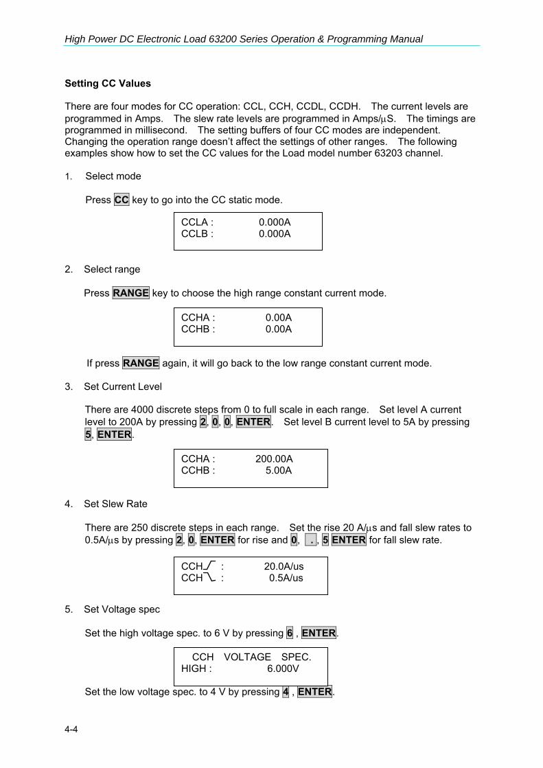
High Power DC Electronic Load 63200 Series Operation & Programming Manual
4-4
Setting CC Values There are four modes for CC operation: CCL, CCH, CCDL, CCDH. The current levels are programmed in Amps. The slew rate levels are programmed in Amps/μS. The timings are programmed in millisecond. The setting buffers of four CC modes are independent. Changing the operation range doesn’t affect the settings of other ranges. The following examples show how to set the CC values for the Load model number 63203 channel. 1. Select mode Press CC key to go into the CC static mode. 2. Select range
Press RANGE key to choose the high range constant current mode.
If press RANGE again, it will go back to the low range constant current mode. 3. Set Current Level
There are 4000 discrete steps from 0 to full scale in each range. Set level A current level to 200A by pressing 2, 0, 0, ENTER. Set level B current level to 5A by pressing 5, ENTER.
4. Set Slew Rate
There are 250 discrete steps in each range. Set the rise 20 A/μs and fall slew rates to 0.5A/μs by pressing 2, 0, ENTER for rise and 0, . , 5 ENTER for fall slew rate.
5. Set Voltage spec
Set the high voltage spec. to 6 V by pressing 6 , ENTER.
Set the low voltage spec. to 4 V by pressing 4 , ENTER.
CCLA : 0.000A CCLB : 0.000A
CCHA : 0.00A CCHB : 0.00A
CCHA : 200.00A CCHB : 5.00A
CCH : 20.0A/us CCH : 0.5A/us
CCH VOLTAGE SPEC. HIGH : 6.000V

Local Operation
4-5
Then the display will go to the first editing page again.
Spec. value can also be programmed by PERCENT under Configure setting. You have to input the CENTER Voltage, and then enter the HIGH and LOW percent to the center voltage.
6. Set dynamic current mode.
Press DYNA key under CC mode, and select current range by RANGE key. Program the high current level to 50A by pressing 5, 0, ENTER keys. Program the low current level to 5A by pressing 5, ENTER keys.
Then set the dynamic function period T1 to 0.1 ms, period T2 to 0.2 ms by pressing 0, . , 1, ENTER and 0, . , 2 , ENTER . The range of dynamic period is from 0.025 ms to 30 Sec.
The slew rate and Voltage Spec settings are same as those of static current mode.
If you press ENTER key, and the blinked data do not go to next, change the configuration setting Enter Data Next to YES.
Setting CR Values The Load CR mode is programmed by pressing CR. The resistance values can be programmed in low voltage (CRL) or high voltage (CRH) range. The current is always in high range. All resistance levels are programmed in Ω. The slew rate is in A/μs. Following examples illustrate how to set the CR values for Load model number 63203. 1. Select range
Press RANGE key to choose the high range CR mode.
If press RANGE again, it will go back to the low range CR mode
CCH VOLTAGE SPEC. LOW : 4.000V
CCDL1: 50.000A CCDL2: 5.000A
CCDLT1: 0.100ms CCDLT2: 0.200ms
CRHA : 500.000Ω CRHB : 500.000Ω

High Power DC Electronic Load 63200 Series Operation & Programming Manual
4-6
2. Set Resistance Level
Set level A resistance level to 200Ω by pressing 2, 0, 0, ENTER. Set level B resistance level to 1Ω by pressing 1, ENTER.
3. Set Slew Rate
Set the rise 20 A/μs and fall slew rates to 0.5A/μs by pressing 2, 0, ENTER for rise and 0, . , 5, ENTER for fall slew rate.
4. Set Voltage spec
Set the high voltage spec. to 6 V by pressing 6 , ENTER.
Set the low voltage spec. to 4 V by pressing 4 , ENTER.
Then the display will go to the first editing page again. Setting CV Values The CV mode for the Load is programmed by pressing CV. The voltage values can be programmed in low voltage (CVL) or high voltage (CVH) range. The current is always in high range. All voltage levels are programmed in Volt. The following examples illustrate how to set CV values for Load model number 63203. 1. Select range
Press RANGE key to choose the low range CV mode.
If press RANGE again, it will go back to the high range CV mode.
CRH : 20.0A/us CRH : 0.5A/us
CRH VOLTAGE SPEC. HIGH : 6.000V
CRH VOLTAGE SPEC. LOW : 4.000V
CRHA : 200.000Ω CRHB : 1.000Ω
CVLA : 16.000V CVLB : 16.000V

Local Operation
4-7
2. Set voltage Level
Set level A voltage level to 10 V by pressing 1, 0, ENTER. Set level B voltage level to 8 V by pressing 8, ENTER.
3. Set Response Speed
There are two response speeds for CV mode, fast and slow for different UUT testing. Refer to Figure 4-2 and Figure 4-3 for transfer functions.
Press 2, ENTER to choose the slow response.
Figure 4-2 CV Response Transfer Function (FAST)
Figure 4-3 CV Response Transfer Function (SLOW)
4. Set Current spec
Set the high current spec. to 8 A by pressing 8, ENTER.
CVLA : 10.000V CVLB : 8.000V
CVL RESPONSE 1: FAST 2. SLOW

High Power DC Electronic Load 63200 Series Operation & Programming Manual
4-8
Set the low current spec. to 4 A by pressing 4, ENTER.
Then the display will go to the first editing page again. Setting CP Values The CP mode for the Load is programmed by pressing CP. The power values can be programmed in low current (CPL) or high current (CPH) range. All power levels are programmed in Walt. The slew rate is in A/μs. The following examples illustrate how to set CP values for Load model number 63203. 1. Select range
Press RANGE key to choose the high range CP mode.
If press RANGE again, it will go back to the low range CP mode 2. Set Power Level
Set level A power level to 200 W by pressing 2, 0, 0, ENTER. Set level B power level to 4000 W by pressing 4, 0, 0, 0, ENTER.
3. Set Slew Rate
Set the rise 20 A/μs and fall slew rates to 0.5A/μs by pressing 2, 0, ENTER for rise and 0, . , 5, ENTER for fall slew rate.
4. Set Voltage spec
Set the high voltage spec. to 6V by pressing 6, ENTER.
CVL CURRENT SPEC. HIGH : 8.000A
CVL CURRENT SPEC. LOW : 4.000A
CPHA : 12.000W CPHB : 12.000W
CPH : 20.0A/us CPH : 0.5A/us
CPHA : 200.000W CPHB : 4000.000W

Local Operation
4-9
Set the low voltage spec. to 4 V by pressing 4, ENTER.
Then the display will go to the first editing page again.
4.2.2 Setting the Program The Electronic Load is able to select customized basic tests, and link them to a program test for automatic execution. The PROG. key is used to select program or recall program for local control. There are ten programs (1-10). Each program has ten sequences to map files from 1 to 100. Program 1 maps files from 1 to 10. Table 4-1 shows the relationship between the program sequence and the corresponding file. Program 1 Sequence No. 1 2 3 4 5 6 7 8 9 10Corresponding File No. 1 2 3 4 5 6 7 8 9 10
Program 2 Sequence No. 1 2 3 4 5 6 7 8 9 10Corresponding File No. 11 12 13 14 15 16 17 18 19 20
: :
Program 10 Sequence No. 1 2 3 4 5 6 7 8 9 10Corresponding File No. 91 92 93 94 95 96 97 98 99 100
Table 4-1 The Relationship of the Program Sequence and the Corresponding File. When running a program you must set its corresponding file parameters first. If one program sequence is not enough for you to test the UUT, you can use program chain function to get more sequences. Press PROG. key, and the LCD will display as follows. Press number 1 -10 followed by ENTER to recall program from EEPROM, or use , keys to edit the program. 1. Setting the Program Chain
The chain function of program enables you to chain program so as to get more sequences for testing. Set program chain number to 0 means no program chained. Program chain function can chain itself for loop test, or other programs. Press 1, ENTER to chain itself for loop test. The default setting is 0.
CPH VOLTAGE SPEC. HIGH : 6.000V
CPH VOLTAGE SPEC. LOW : 4.000V
PROGRAM SELECT No: 1
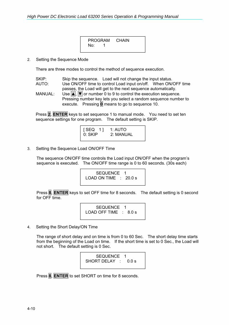
High Power DC Electronic Load 63200 Series Operation & Programming Manual
4-10
2. Setting the Sequence Mode
There are three modes to control the method of sequence execution. SKIP: Skip the sequence. Load will not change the input status. AUTO: Use ON/OFF time to control Load input on/off. When ON/OFF time passes, the Load will get to the next sequence automatically. MANUAL: Use , or number 0 to 9 to control the execution sequence.
Pressing number key lets you select a random sequence number to execute. Pressing 0 means to go to sequence 10.
Press 2, ENTER keys to set sequence 1 to manual mode. You need to set ten sequence settings for one program. The default setting is SKIP.
3. Setting the Sequence Load ON/OFF Time
The sequence ON/OFF time controls the Load input ON/OFF when the program’s sequence is executed. The ON/OFF time range is 0 to 60 seconds. (30s each)
Press 8, ENTER keys to set OFF time for 8 seconds. The default setting is 0 second for OFF time.
4. Setting the Short Delay/ON Time
The range of short delay and on time is from 0 to 60 Sec. The short delay time starts from the beginning of the Load on time. If the short time is set to 0 Sec., the Load will not short. The default setting is 0 Sec.
Press 8, ENTER to set SHORT on time for 8 seconds.
PROGRAM CHAIN No: 1
SEQUENCE 1 LOAD ON TIME : 20.0 s
SEQUENCE 1 LOAD OFF TIME : 8.0 s
[ SEQ 1 ] 1: AUTO 0: SKIP 2: MANUAL
SEQUENCE 1 SHORT DELAY : 0.0 s

Local Operation
4-11
5. Setting the Sequence P/F Delay/ON Time
The sequence Pass/Failure Delay/ON time let you set the delay time for P/F checking and on time for how long it checks when load condition changes. The failure status of the sequence will latch when a program is executed. It means that any failure will be memorized even when the UUT becomes stable within the specifications later. The range of P/F delay and ON time is from 0 to 60 seconds. Press 1, ENTER to set the sequence P/F delay time for 1 second and then 5, ENTER for P/F on time for 5 seconds. Both default setting are 0 second.
4.2.3 Running the Program Press LOAD ON/OFF to run program when the program function is selected. The display shows as below. The upper line shows the executed program and sequence number while the lower line shows the Load, key, test result and short status. ON/OFF: It shows the Load input status. KEY: It displays when MANUAL mode is active and waiting for key input. PASS/FAIL: It shows the test result compared with SPEC setting. S: It display if Load is Short now. When executing the program, the setting of sequence will recall files from EEPROM, and the SPEC function is always ON. All function keys are disabled until LOAD ON/OFF is pressed to stop the program execution, or the program run finishes. When the program run stops or finishes, the LCD will display as follows. It means that all sequences have passed in the program tests. If the test fails, LCD will show as follows.
SEQUENCE 1 SHORT ON TIME : 8.0 s
SEQUENCE 1 P / F DELAY : 1.0 s
SEQUENCE 1 P / F ON TIME : 8.0 s
PROG. 1 SEQ. 1 [ON ][ KEY ] [ PASS ] [ S ]
PROGRAM OFF RESULT : PASS

High Power DC Electronic Load 63200 Series Operation & Programming Manual
4-12
PROG. XX indicates the file number of the program failed, 1 to 10. In addition, 1, 2, 3...10 shown by LCD stand for the failed sequence numbers. During program chain testing, if the failed program files are more than one set, you can use , to read the contents of failed programs.
4.2.4 Setting the Specification The GO/NG key is to enable/disable specification checking function. The Load will compare measurement data with the set specifications for HIGH and LOW boundary when the SPEC TEST is ON, and the LED, GO/NG, is lighted on the panel. To set specifications for the load; please refer to the section 3.5 at the end of each mode for parameters setting. The specification unit for CC, CR, and CP modes is volt while CV mode is current. There are three levels for each mode: CENTER, HIGH and LOW. The CENTER level must be set by the value of channel input reference level. The HIGH and LOW levels can be set by the value or percentage selected in configuration SPEC.ENTRY MODE. The HIGH/LOW percentage range is from 0 to 100%. The default setting of HIGH and LOW is 100%. The CENTER value is half of the range. Please refer to section 4.2.5 for the specification selection set by Value or Percentage.
4.2.5 Setting the Configuration The Electronic Load provides useful features such as Von point, Current limit, Auto Load On, etc. To use these powerful features, you must set relevant parameters in accordance with application needs by the configuration setup. This procedure is only needed for initial setup of a test operation. The configuration of the Load is stored in EEPROM. To set configuration you must press the CONF key. Set the voltage range for CC, CP mode. There are two voltage ranges for CC or CP mode. High range is for high voltage and low range is for low voltage so as to get better voltage resolution. The default setting of V range is HIGH. Set Von Protection in two ways. 1. When Von Protection is set to YES, the default voltage protection value will be set, see 3.16 Von Protection for detail description. 2. When NO is selected there will be no default voltage protection value. A warning of “CAUTION: If Voltage rise of UUT is < 250us, it may cause damages of 63200s.” will prompt when NO is set.
PROG. XX Err. REPORT 1, 2, 3,…….10
CC, CP V RANGE SELECT 1: HIGH 2: LOW
Von PROTECTION 1:YES 2:NO
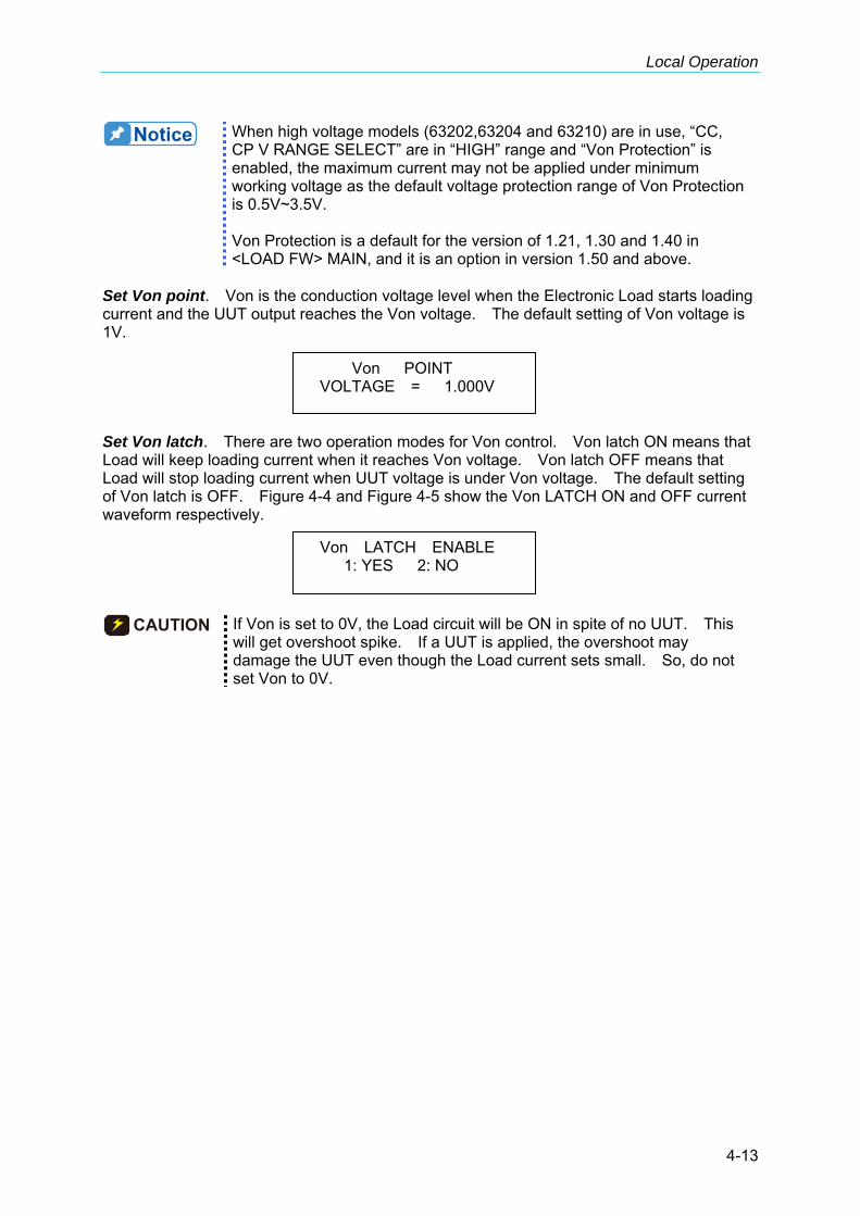
Local Operation
4-13
When high voltage models (63202,63204 and 63210) are in use, “CC, CP V RANGE SELECT” are in “HIGH” range and “Von Protection” is enabled, the maximum current may not be applied under minimum working voltage as the default voltage protection range of Von Protection is 0.5V~3.5V. Von Protection is a default for the version of 1.21, 1.30 and 1.40 in <LOAD FW> MAIN, and it is an option in version 1.50 and above.
Set Von point. Von is the conduction voltage level when the Electronic Load starts loading current and the UUT output reaches the Von voltage. The default setting of Von voltage is 1V. Set Von latch. There are two operation modes for Von control. Von latch ON means that Load will keep loading current when it reaches Von voltage. Von latch OFF means that Load will stop loading current when UUT voltage is under Von voltage. The default setting of Von latch is OFF. Figure 4-4 and Figure 4-5 show the Von LATCH ON and OFF current waveform respectively.
CAUTION If Von is set to 0V, the Load circuit will be ON in spite of no UUT. This will get overshoot spike. If a UUT is applied, the overshoot may damage the UUT even though the Load current sets small. So, do not set Von to 0V.
Von POINT VOLTAGE = 1.000V
Von LATCH ENABLE 1: YES 2: NO
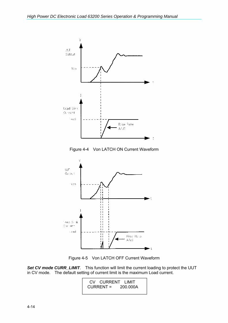
High Power DC Electronic Load 63200 Series Operation & Programming Manual
4-14
Figure 4-4 Von LATCH ON Current Waveform
Figure 4-5 Von LATCH OFF Current Waveform
Set CV mode CURR_LIMIT. This function will limit the current loading to protect the UUT in CV mode. The default setting of current limit is the maximum Load current.
CV CURRENT LIMIT CURRENT = 200.000A

Local Operation
4-15
Set sign of voltage for display. The Electronic Load will show minus sign of the voltage if MINUS is selected. No sign will show if select PLUS. The default setting is PLUS. Selecting MINUS of SIGN OF VOLT. will occupy one digit. The displayed digits are five. Set POWER/OHM for display. The right one of the three 7-segment LEDs can be selected to display POWER or OHM measurement data. The default setting is POWER. The LED “OHMS” will be lighted if you select OHM by pressing 2, ENTER. Set the specifications of entry mode. The specifications of Load can be set by VALUE or Percentage for HIGH and LOW data. The percentage values refer to CENTER value of specification. The default setting of SPEC entry mode is percentage. Select data entry mode by ENTER. If YES is selected for data entry, the setting will go to the next one after pressing ENTER. If NO is selected for data entry, the setting will remain at the same line for you to change it again and again. The default setting is NO. Select SOUND ENABLE. When you press the key on the module, it will produce a sound if sound = YES. The default setting for sound is YES. Select Load input status when it is powered ON. If YES is selected, the module will be active according to AUTO LOAD ON mode setting. The default setting of AUTO LOAD ON is NO. Select the load on mode if AUTO LOAD ON is ON. If LOAD is selected, the Load will be active as DEFAULT setting. If PROG is selected, the Load will be active as the program saved last time. The default setting of AUTO LOAD ON MODE is LOAD.
SIGN OF VOLTAGE 1. PLUS 2. MINUS
POWER / OHM SELECT 1: POWER 2: OHM
SPEC. ENTRY MODE 1: VALUE 2: PCet
ENTER DATA NEXT 1: YES 2: NO
SOUND ENABLE 1: YES 2: NO
AUTO LOAD ON 1: YES 2: NO
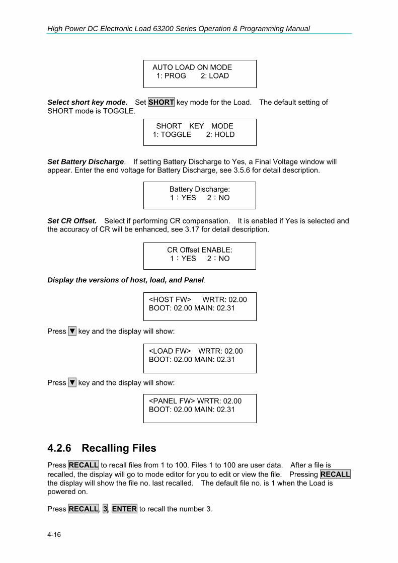
High Power DC Electronic Load 63200 Series Operation & Programming Manual
4-16
Select short key mode. Set SHORT key mode for the Load. The default setting of SHORT mode is TOGGLE. Set Battery Discharge. If setting Battery Discharge to Yes, a Final Voltage window will appear. Enter the end voltage for Battery Discharge, see 3.5.6 for detail description. Set CR Offset. Select if performing CR compensation. It is enabled if Yes is selected and the accuracy of CR will be enhanced, see 3.17 for detail description. Display the versions of host, load, and Panel. Press key and the display will show: Press key and the display will show:
4.2.6 Recalling Files Press RECALL to recall files from 1 to 100. Files 1 to 100 are user data. After a file is recalled, the display will go to mode editor for you to edit or view the file. Pressing RECALL the display will show the file no. last recalled. The default file no. is 1 when the Load is powered on. Press RECALL, 3, ENTER to recall the number 3.
AUTO LOAD ON MODE 1: PROG 2: LOAD
SHORT KEY MODE 1: TOGGLE 2: HOLD
<HOST FW> WRTR: 02.00 BOOT: 02.00 MAIN: 02.31
<LOAD FW> WRTR: 02.00 BOOT: 02.00 MAIN: 02.31
<PANEL FW> WRTR: 02.00 BOOT: 02.00 MAIN: 02.31
Battery Discharge: 1:YES 2:NO
CR Offset ENABLE: 1:YES 2:NO

Local Operation
4-17
The data of the Load will be recalled when you execute file recall.
4.2.7 Saving File/Default/Program There are 100 file locations (1 to 100) for you to save files. Press SAVE, 2, 0, ENTER to save a file to location 20. Press SAVE, , until the display shows as follows. The DEFAULT states are used for Electronic Load after power-on. Press 1, ENTER to save DEFAULT to EEPROM. Press SAVE, , until the display shows as follows. Press 1, ENTER to save program.
4.2.8 Going To Local The CONF./LOCAL key operates as local key when Electronic Load is in remote mode. You can press CONF./LOCAL key to go to local operation when Load is in remote state. In local operation, CONF./LOCAL key operates as CONF key.
4.2.9 Setting System and RS-232C Connection GPIB Address setting. Press 8, ENTER to set the Load GPIB address to 8. RS485 Address setting. Press 3, ENTER to set the Load RS485 address to 3. This is for setting the models ID when used in parallel mode.
RECALL FILE FILE NO : 3
SAVE FILE FILE NO : 20
SAVE DEFAULT 1: YES 2: NO
SAVE PROGRAM 1: YES 2: NO
GPIB ADDRESS 8
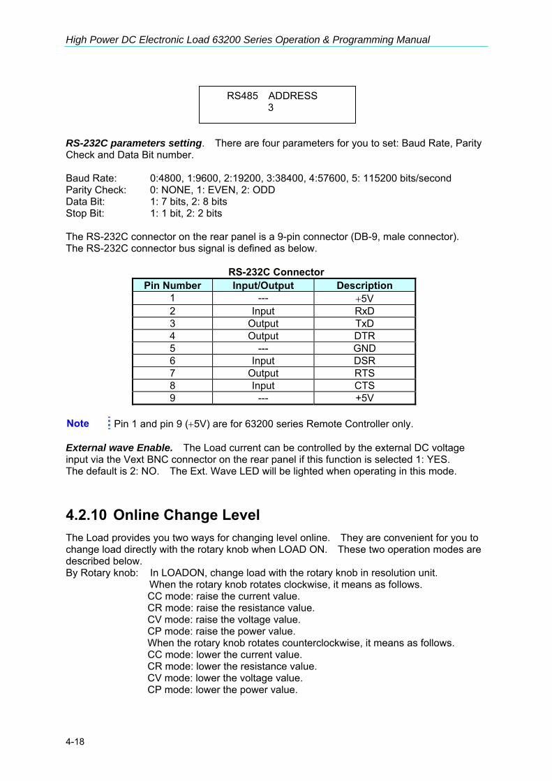
High Power DC Electronic Load 63200 Series Operation & Programming Manual
4-18
RS-232C parameters setting. There are four parameters for you to set: Baud Rate, Parity Check and Data Bit number. Baud Rate: 0:4800, 1:9600, 2:19200, 3:38400, 4:57600, 5: 115200 bits/second Parity Check: 0: NONE, 1: EVEN, 2: ODD Data Bit: 1: 7 bits, 2: 8 bits Stop Bit: 1: 1 bit, 2: 2 bits The RS-232C connector on the rear panel is a 9-pin connector (DB-9, male connector). The RS-232C connector bus signal is defined as below.
RS-232C Connector Pin Number Input/Output Description
1 --- +5V 2 Input RxD 3 Output TxD 4 Output DTR 5 --- GND 6 Input DSR 7 Output RTS 8 Input CTS 9 --- +5V
Note Pin 1 and pin 9 (+5V) are for 63200 series Remote Controller only. External wave Enable. The Load current can be controlled by the external DC voltage input via the Vext BNC connector on the rear panel if this function is selected 1: YES. The default is 2: NO. The Ext. Wave LED will be lighted when operating in this mode.
4.2.10 Online Change Level The Load provides you two ways for changing level online. They are convenient for you to change load directly with the rotary knob when LOAD ON. These two operation modes are described below. By Rotary knob: In LOADON, change load with the rotary knob in resolution unit.
When the rotary knob rotates clockwise, it means as follows. CC mode: raise the current value. CR mode: raise the resistance value. CV mode: raise the voltage value. CP mode: raise the power value. When the rotary knob rotates counterclockwise, it means as follows. CC mode: lower the current value. CR mode: lower the resistance value. CV mode: lower the voltage value. CP mode: lower the power value.
RS485 ADDRESS 3

Local Operation
4-19
By CURSOR EDIT: In LOAD ON, press the mode key CC, CR, CV, or CP to make the display show numeric values for the setting. Press CURSOR EDIT to see the cursor blinking on the display. Press , keys to move the cursor to the digit you want to edit. Change the value by rotary knob. Press the CURSOR EDIT key again to disable the cursor.

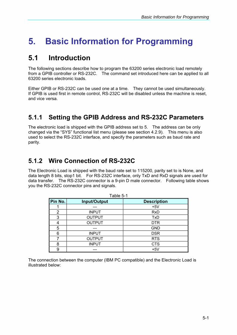
Basic Information for Programming
5-1
5. Basic Information for Programming
5.1 Introduction The following sections describe how to program the 63200 series electronic load remotely from a GPIB controller or RS-232C. The command set introduced here can be applied to all 63200 series electronic loads. Either GPIB or RS-232C can be used one at a time. They cannot be used simultaneously. If GPIB is used first in remote control, RS-232C will be disabled unless the machine is reset, and vice versa.
5.1.1 Setting the GPIB Address and RS-232C Parameters The electronic load is shipped with the GPIB address set to 5. The address can be only changed via the “SYS” functional list menu (please see section 4.2.9). This menu is also used to select the RS-232C interface, and specify the parameters such as baud rate and parity.
5.1.2 Wire Connection of RS-232C The Electronic Load is shipped with the baud rate set to 115200, parity set to is None, and data length 8 bits, stop1 bit. For RS-232C interface, only TxD and RxD signals are used for data transfer. The RS-232C connector is a 9-pin D male connector. Following table shows you the RS-232C connector pins and signals.
Table 5-1 Pin No. Input/Output Description
1 --- +5V 2 INPUT RxD 3 OUTPUT TxD 4 OUTPUT DTR 5 --- GND 6 INPUT DSR 7 OUTPUT RTS 8 INPUT CTS 9 --- +5V
The connection between the computer (IBM PC compatible) and the Electronic Load is illustrated below:

High Power DC Electronic Load 63200 Series Operation & Programming Manual
5-2
PIN
1
2
3
4
5
6
7
9
8
IBM PC
DCD
RX
TX
DTR
GND
DSR
RTS
RI
CTS
Electronic Load
No Connection
RX
TX
No Connection
GND
No Connection
No Connection
No Connection
No Connection
5.2 GPIB Capability of the Electronic Load Table 5-2
GPIB Capability Response Interface Functions
Talker/Listener
All electronic load functions are programmable over the GPIB. The electronic load can send and receive messages over the GPIB. Status information is sent using a serial poll.
AH1, SH1, T6, L4
Service Request The electronic load will set the SRQ line true if there is an enabled service request condition. SR1
Remote/Local
In local mode, the electronic load is controlled from the front panel but will also execute commands sent over the GPIB. The electronic load powers up in local mode and remains there until it receives a command over the GPIB. Once the electronic load is in remote mode, REMOTE will be shown on the front panel LCD, all front panel keys except LOCAL are disabled. Pressing LOCAL key on the front panel will return to local mode. Local can be disabled using local lockout, so only the controller or the power switch can return to local mode.
RL1

Basic Information for Programming
5-3
5.3 RS-232C in Remote Control When you use RS-232C in remote control, you have to send the remote command CONFigure : REMote ON first to let control procedure enter into remote state, and then execute other command set. When control comes to an end, you have to send the command CONFigure : REMote OFF to let control procedure return to local operation mode. The RS-232C control commands are same as those of GPIB. When the RS-232C command string comes to an end for sending, <nl> should be added. Its ASCII code is 0A hexadecimal (or 10 decimal).


Introduction to Programming
6-1
6. Introduction to Programming
6.1 Basic Definition GPIB statement includes instrument control and query commands. A command statement sends an instruction to the electronic load and query command request information from the electronic load. Simple Command A simple command statement consists of a command or keyword usually followed by a parameter or data:
LOAD ON or LOAD:SHORT OFF
Compound Command When two or more keywords are connected by colons (:), it creates a compound command statement. The last keyword usually is followed by a parameter or data: CURRent:STATic:L1 3 or CONFigure:VOLTage:RANGe H Query Command A simple query command consists of a keyword followed by a question mark: MEASure:VOLTage? MEASure:CURRent? or CHAN? Forms of Keywords Every keyword has two forms:
Long-Form In this form, the word is spelled out completely to identify its function. For instance, CURRENT, VOLTAGE, and MEASURE are long-form keywords.
Short-Form In this form, the word contains only the first three or four letters of the long-form. For instance, CURR, VOLT, and MEAS are short-form keywords.
In keyword definitions and diagrams, the short-form part of each keyword is emphasized in UPPER CASE letters to help you remember it. However, the electronic load will accept Volt, volt, voltage, VOLTAGE, volTAGE, etc. regardless to which form you apply. If the keyword is incomplete, for example, “VOL” or “curre”, it will not be recognized.

High Power DC Electronic Load 63200 Series Operation & Programming Manual
6-2
6.2 Numerical Data Formats Chroma 63200 electronic load accepts the numerical data type listed in Table 6-1. Numeric data may be followed by a suffix to specify the dimension of the data. A suffix may be preceded by a multiplier. Chroma 63200 makes use of the suffixes listed in Table 6-2 and multipliers listed in Table 6-3.
Table 6-1 Numerical Data Type Symbol Description Example
NR1 Digits with no decimal point. The decimal point is assumed to be to the right of the least-significant digit.
123, 0123
NR2 Digits with a decimal point. 123., 12.3, 0.123, .123NR3 Digit with a decimal point and an exponent. 1.23E+3, 1.23E-3 NRf Flexible decimal form that includes NR1 or NR2 or NR3. 123, 12.3, 1.23E+3
NRf+ Expanded decimal form that includes NRf and MIN, MAX. MIN and MAX are the minimum and maximum limit values for the parameter.
123, 12.3, 1.23E+3, MIN, MAX
Table 6-2 Suffix Elements
Mode Class Preferred Suffix Secondary Suffix Referenced Unit CC Current A Ampere CR Resistance OHM Ohm CV Amplitude V Volt CP Power W Watt ALL Time S Second ALL Slew Rate A/μS Amperes/micro Second
Table 6-3 Suffix Multipliers
Multiplier Mnemonic Definition 1E6 MA mega 1E3 K kilo 1E-3 M milli 1E-6 U Micro 1E-9 N Nano
6.3 Character Data Formats For command statements, the <NRf+> data format permits entry of required characters. For query statements, character strings may be returned in either of the forms shown in the following table. It depends on the length of the returned string. Symbol Character Form
Crd Character Response Data. They permit the return up to 12 characters.
aard Arbitrary ASCII Response Data. They permits the return of undelimited 7-bit ASCII. This data type is an implied message terminator (refer to Separators and Terminators).

Introduction to Programming
6-3
6.4 Separators and Terminators In addition to keywords and parameters, GPIB program statements require the following: Data Separators: Data must be separated from the previous command keyword by a space. This is shown in examples as a space (CURR 3) and on diagrams by the letters SP inside a circle. Keyword Separators: Keywords (or headers) are separated by colon (:), semicolon (;), or both. For example: LOAD:SHOR ON MEAS:CURR?;VOLT? CURR:STAT:L1 3;:VOLT:L1 5
Program Line Separators: A terminator to inform GPIB that it has reached the end of a statement. Normally, this is sent automatically by your GPIB programming statements. Termination also occurs with other terminator codes, such as EOI. In this manual, the terminator is assumed at the end of each example line of code. If it needs to be indicated, it is shown by the symbol <nl>, which indicates “new line” and represents the ASCII coded byte as 0A hexadecimal (or 10 decimal). Traversing the Command Tree: The colon “:” separates keywords from each other which represents changes in branch
level to the next lower one. For example: CONF:VOLT:ON 5 CONF is a root-level command, VOLT is the first branch, and ON is the second branch.
Each “:” moves the command interpretation downward to the next branch. The semicolon “;” allows you to combine command statements into one line. It returns
the command interpretation to the previous colon. For example: Combine the following two command statements:
RES:RISE 100 <nl> and RES:L1 400 <nl>
which can be formed into one command line as follows:
RES:RISE 100;L1 400 <nl>
To return to the root-level form you can 1. Enter a new-line character. This is symbolized as “<nl>” and can be linefeed “LF”
or/and end-of-line “EOL”. Or else, 2. Enter a semicolon followed by a colon “;:”.

High Power DC Electronic Load 63200 Series Operation & Programming Manual
6-4
Please refer to the following figure. 1. (root):VOLT:L1: 30<nl>
Starting a New Line to return to the Root.
2. (root):SPEC:VOLT:H 30; :L 5;: (root)RES:L1 400; :RISE 1000;:

Language Dictionary
7-1
7. Language Dictionary Commands for operating the 63200 Electronic Load remotely are grouped into subsystems. Each command belonging to the same subsystem is arranged in alphabetic order. A syntax chart of the subsystem that contains the commands in the same group is included. Sub- systems are ordered alphabetically according to their names in the following sections.
7.1.1 Common Commands Common commands defined by the IEEE488.2 standard are generic commands and queries. The first part of the language dictionary covers the commands. Each of them has a leading “*”.
Common Commands Syntax *CLS Clear status *ESE <NR1> Standard event status enable *ESE? Return standard event status enable *ESR? Return event status enable *IDN? Return instrument identification *OPC Enable “operation complete” bit in ESR *OPC? Return a “1” when operation complete *RCL <NRf> Recall instrument state *RST Reset *SAV <NRf> Save instrument state *SRE <NR1> Set service request enable register *SRE? Return service request enable register *STB? Return status byte
7.1.2 Common Command Dictionary *CLS Clear Status Command Description This command clears the following actions:
1. Clear Questionable Status Event register 2. Clear Standard Event Status Event register 3. Clear Status Byte 4. Clear the Error Queue
Syntax *CLS Parameter None *ESE Standard Event Status Enable Command/Query Description This command sets the condition of the Standard Event Status
Enable register to determine which event the Standard Event Status Event register (see *ESR?) is allowed to set the ESB (Event Summary Bit) for the Status Byte register. A "1" in the bit position enables the corresponding event. All the events enabled by Standard Event Status Event register are logically ORed to cause the ESB (bit 5) of the Status Byte register to be set. See the descriptions of these registers in Chapter 8 Status Reporting.
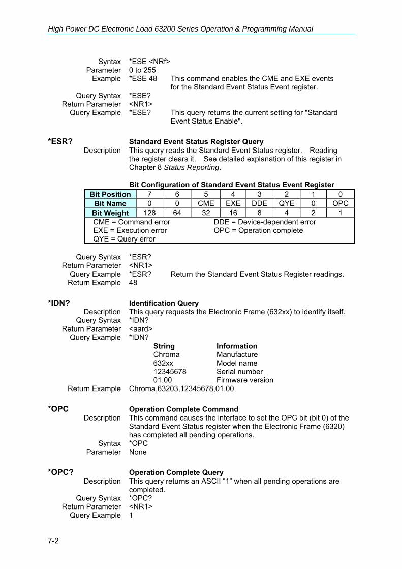
High Power DC Electronic Load 63200 Series Operation & Programming Manual
7-2
Syntax *ESE <NRf> Parameter 0 to 255 Example *ESE 48 This command enables the CME and EXE events for the Standard Event Status Event register. Query Syntax *ESE? Return Parameter <NR1> Query Example *ESE? This query returns the current setting for "Standard Event Status Enable". *ESR? Standard Event Status Register Query Description This query reads the Standard Event Status register. Reading the register clears it. See detailed explanation of this register in Chapter 8 Status Reporting.
Bit Configuration of Standard Event Status Event Register Bit Position 7 6 5 4 3 2 1 0
Bit Name 0 0 CME EXE DDE QYE 0 OPCBit Weight 128 64 32 16 8 4 2 1 CME = Command error DDE = Device-dependent error EXE = Execution error OPC = Operation complete QYE = Query error
Query Syntax *ESR? Return Parameter <NR1> Query Example *ESR? Return the Standard Event Status Register readings. Return Example 48 *IDN? Identification Query Description This query requests the Electronic Frame (632xx) to identify itself. Query Syntax *IDN? Return Parameter <aard> Query Example *IDN? String Information Chroma Manufacture 632xx Model name 12345678 Serial number 01.00 Firmware version Return Example Chroma,63203,12345678,01.00 *OPC Operation Complete Command Description This command causes the interface to set the OPC bit (bit 0) of the Standard Event Status register when the Electronic Frame (6320) has completed all pending operations. Syntax *OPC Parameter None *OPC? Operation Complete Query Description This query returns an ASCII “1” when all pending operations are completed. Query Syntax *OPC? Return Parameter <NR1> Query Example 1
Language Dictionary
7-3
*RCL Recall Instrument State Command Description This command restores the electronic load to a state that was previously stored in memory with *SAV command to the specified location (see *SAV). Syntax *RCL <NRf> Parameter 1 to 100 Example *RCL 50 *RST Reset Command Description This command forces an ABORt, *CLS, LOAD:PROT:CLE command. Syntax *RST Parameter None *SAV Save Command Description This command stores the present state of electronic load in a
specified location in memory. Syntax *SAV <NRf> Parameter 1 to 100 Example *SAV 50 *SRE Service Request Enable Command/Query Description This command sets the condition of the Service Request Enable
register to determine which event of the Status Byte register (see *STB) is allowed to set the MSS (Master Status Summary) bit. A "1" in the bit position enabled by bits is logically ORed to cause Bit 6 (the Master Summary Status Bit) of the Status Byte register to be set. See details regarding the Status Byte register in Chapter 8 Status Reporting.
Syntax *SRE <NRf> Parameter 0 to 255
Example *SRE 24 Enable the QUES and MAV bit of the Service Request Enable
Query Syntax *SRE? Return Parameter <NR1> Query Example *SRE? Return the current setting for "Service Request Enable". *STB? Read Status Byte Query Description This query reads the Status Byte register. Note that the MSS
(Master Summary Status) bit is returned in Bit 6 instead of RQS bit. This bit indicates if the electronic load has at least one reason for requesting service. *STB? does not clear the Status Byte register. It is cleared only when subsequent action has cleared all bits set. Refer to Chapter 8 Status Reporting for more information about this register.
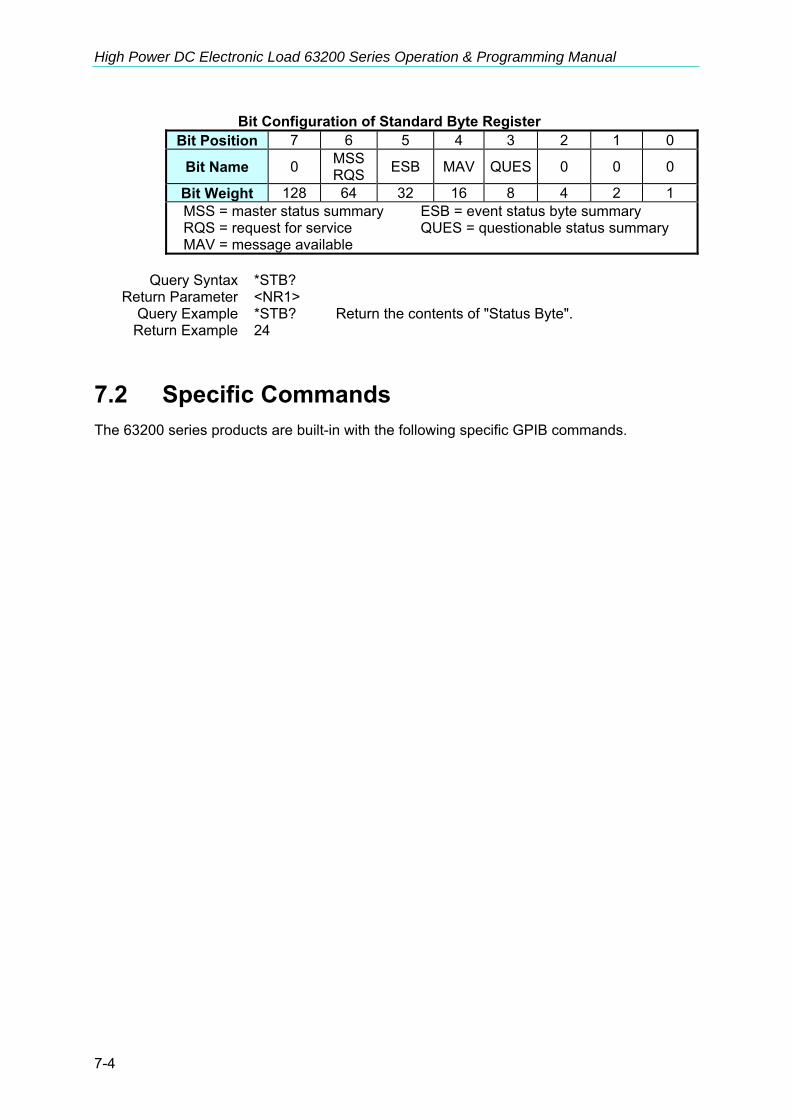
High Power DC Electronic Load 63200 Series Operation & Programming Manual
7-4
Bit Configuration of Standard Byte Register Bit Position 7 6 5 4 3 2 1 0
Bit Name 0 MSS RQS ESB MAV QUES 0 0 0
Bit Weight 128 64 32 16 8 4 2 1 MSS = master status summary ESB = event status byte summary RQS = request for service QUES = questionable status summary MAV = message available
Query Syntax *STB? Return Parameter <NR1> Query Example *STB? Return the contents of "Status Byte". Return Example 24
7.2 Specific Commands The 63200 series products are built-in with the following specific GPIB commands.

Language Dictionary
7-5
7.2.1 CONFigure Sub-system CONFigure
:AUTO :LOAD :MODE :DISPlay :KEY :REMote :SAVE :SOUNd :VOLTage :LATCh :RESet :ON :POLarity :RANGe :PROTection :BATT :VOLT :Capacity :TIME :CROFFSET CONFigure:AUTO:LOAD Description Set if the load module will do Auto Load On during power-on. Syntax CONFigure:AUTO:LOAD <NR1 | CHAR> Parameter 0 | OFF, 1 | ON Example CONF:AUTO:LOAD ON Start Auto Load On during power on. CONF:AUTO:LOAD OFF Close Auto Load On during power on. Query Syntax CONFigure:AUTO:LOAD? Return Parameter 0 | 1 Query Example CONF: AUTO: LOAD? Return Example 0 (OFF) Return the status of Auto Load On CONFigure:AUTO:MODE Description Set type of Auto Load On as LOAD ON or PROGRAM ON. Syntax CONFigure:AUTO:MODE <NR1 | CHAR> Parameter 0 | PROGRAM, 1 | LOAD
Example CONF:AUTO:MODE LOAD Set Auto Load On as general Load On.
CONF:AUTO:MODE PROGRAM Set Auto Load On as Program On.
Query Syntax CONFigure:AUTO:MODE? Return Parameter 0 | 1 Query Example CONF:AUTO:MODE? Return the execution type of Auto
Load On. Return Example 0 ( PROGRAM)

High Power DC Electronic Load 63200 Series Operation & Programming Manual
7-6
CONFigure:DISPlay Description Set measure display mode Command Syntax CONFigure:DISPlay <NR1 | CHAR> Parameter 0 | RESISTANCE, 1 | POWER Example CONF:DISP POWER Set the power display mode. CONF:DISP 0 Set resistance display mode. Query Syntax CONFigure:DISPlay? Return Parameter 0 | 1 Query Example CONF:DISP? Return the execution type of display mode. Return Example 1 (POWER) CONFigure:KEY Description Set enter data key mode Command Syntax CONFigure:KEY <NR1 | CHAR> Parameter 0 | HOLD, 1 | NEXT Example CONF:KEY 1 Set enter data next mode. CONF:KEY HOLD Set enter data hold mode. Query Syntax CONFigure:KEY? Return Parameter 0 | 1 Query Example CONF:KEY? Return the execution type to enter data mode. Return Example 1 ( NEXT ) CONFigure:REMote Description Set the status of remote control (only effective in RS-232C). Syntax CONFigure:REMote <NR1 | CHAR> Parameter 0 | OFF, 1 | ON Example CONF:REM ON Set to remote control. CONFigure:SAVE Description Save the setting of CONFigure for next power-on use. Syntax CONFigure:SAVE Parameter None Example CONF:SAVE CONFigure:SOUNd Description Set the buzzer sound ON/OFF. Syntax CONFigure:SOUNd <NR1 | CHAR> Parameter 0 | OFF, 1 | ON Example CONF:SOUN 0 CONF:SOUN OFF Query Syntax CONFigure:SOUNd? Return Parameter 0 | 1 Query Example CONF:SOUN? Return the control status of the buzzer sound. Return Example 0 (OFF ) CONFigure:VOLTage:LATCh Description Set the action type to Von. Syntax CONFigure:VOLTage:LATCh <NR1 | CHAR> Parameter 0 | OFF, 1 | ON Example CONF:VOLT:LATC 1 Set the action type to Von as Latch. CONF:VOLT:LATC OFF Set the action type to Von as Non
Latch (Refer to the former part of this manual for detailed).
Query Syntax CONFigure:VOLTage:LATCh?

Language Dictionary
7-7
Return Parameter 0 | 1 Query Example CONF:VOLT: LATC? Return the action type to Von. Return Example 0 (OFF) CONFigure:VOLTage:LATCh:RESet Description Reset Von signal. Syntax CONFigure:VOLTage:LATCh:RESet Parameter None Example CONF:VOLT:LATC:RES CONFigure:VOLTage:ON Description Set the voltage of loading current to on. Syntax CONFigure:VOLTage:ON <NRf> [suffix] Parameter For valid voltage range refer to respective specification. Example CONF:VOLT:ON 1 Set Von=1V. CONF:VOLT:ON 300mV Set Von=300mV. Query Syntax CONFigure:VOLTage:ON? Return Parameter <NR2> [Unit=Voltage] Query Example CONF:VOLT:ON? Return the setting of Von value. Return Example 3.5 CONFigure:VOLTage:POLarity Description Set the voltage display polarity. Syntax CONFigure:VOLTage:POLarity <NR1 | CHAR> Parameter 0 | MINUS, 1 | PLUS, Example CONF:VOLT:POL 0 Set voltage display to minus. CONF:VOLT:POL PLUS Set voltage display to plus. Query Syntax CONFigure:VOLTage:POLarity? Return Parameter 0 | 1 Query Example CONF:VOLT:POL? Return the display polarity. Return Example 0 ( MINUS ) CONFigure:VOLTage:RANGe Description Set voltage measurement range in CC mode. Syntax CONFigure:VOLTage:RANGe <NR1 | CHAR> Parameter 0 | L, 1 | H Example CONF:VOLT:RANG 1 Set full-range to High. CONF:VOLT:RANG L Set full-range to Low. Query Syntax CONFigure:VOLTage:RANGe? Return Parameter 0 | 1 Query Example CONF:VOLT:RANG? Return Voltage range. Return Example 1 ( H ) CONFigure:VOLTage:PROTection Description Set Load On protection. Syntax CONFigure:VOLTage:PROTection <NR1 | CHAR> Parameter 0 | OFF, 1 | ON Example CONF:VOLT:PROT 1 Enable Load On protection. CONF:VOLT:PROT OFF Disable Load On protection. Query Syntax CONFigure:VOLTage:PROTection? Return Parameter 0 | 1 Query Example CONF:VOLT:PROT? Return Load On protection. Return Example 1 ( ON )

High Power DC Electronic Load 63200 Series Operation & Programming Manual
7-8
CONFigure:BATT Description Set the battery discharge measurement. Syntax CONFigure:BATT <NR1 | CHAR> Parameter 0 | OFF, 1 | ON Example CONF:BATT 1 Enable battery discharge. CONF:BATT OFF Disable battery discharge. Query Syntax CONFigure:BATT? Return Parameter 0 | 1 Query Example CONF:BATT? Return battery discharge state. Return Example 1 ( ON ) CONFigure:BATT:VOLT Description Set the end voltage for battery discharge. Syntax CONFigure:BATT:VOLT <NRf> [suffix] Parameter For valid voltage range refer to respective specification. Example CONF:BATT:VOLT 1 Set end voltage =1V. CONF:BATT:VOLT 500mV Set end voltage =500mV. Query Syntax CONFigure:BATT:VOLT? Return Parameter <NR2> [Unit=Voltage]
Query Example CONF:BATT:VOLT? Return the end voltage of battery discharge.
Return Example 2.5 CONFigure:BATT:Capacity? Description Query the battery capacity when doing battery discharge. Query Syntax CONFigure:BATT:Capacity? Return Parameter <NR2> [Unit=Ah] Query Example CONF:BATT:Capacity? Return the battery capacity. Return Example 2.5 CONFigure:BATT:TIME? Description Query the battery discharge duration. Query Syntax CONFigure:BATT:TIME? Return Parameter <NR2> [Unit=Second] Query Example CONF:BATT:TIME? Return the battery discharge duration. Return Example 3 CONFigure:CROFFSET Description Set compensation mechanism in CR mode. Syntax CONFigure:CROFFSET <NR1 | CHAR> Parameter 0 | OFF, 1 | ON Example CONF:CROFFSET 1 Enable CR compensation. CONF:CROFFSET OFF Disable CR compensation. Query Syntax CONFigure:CROFFSET? Return Parameter 0 | 1 Query Example CONF:CROFFSET? Return CR compensation state. Return Example 1 ( ON )

Language Dictionary
7-9
7.2.2 COMMunicate Sub-system COMMunicate
:ADDRess :GPIB :RS485 :SERial :BAUD :BITS :PARity :SBITs
COMMunicate:ADDRess:GPIB Description Set the GPIB address Syntax COMMunicate:ADDRess:GPIB <NR1> Parameter 1 – 30 Example COMM:ADDR:GPIB 16 Query Syntax COMMunicate:ADDRess:GPIB? Return Parameter <NR1> Query Example COMM:ADDR:GPIB? Return GPIB address. Return Example 16 COMMunicate:ADDRess:RS485 Description Set the RS485 address Syntax COMMunicate:ADDRess:RS485 <NR1> Parameter 1 – 5 Example COMM:ADDR:RS485 5 Query Syntax COMMunicate:ADDRess:RS485? Return Parameter <NR1> Query Example COMM:ADDR:RS485? Return RS485 address. Return Example 5 COMMunicate:SERial:BAUD Description Set the baud rate Syntax COMMunicate:SERial:BAUD <NR1 | CHAR> Parameter 0 | BAUD_48, 1 | BAUD_96, 2 | BAUD_192, 3 | BAUD_384, 4 | BAUD_576, 5 | BAUD_1152 Example COMM: SER:BAUD 5 COMM: SER:BAUD BAUD_1152 Query Syntax COMMunicate:SERial:BAUD? Return Parameter 0 | 1 | 2 | 3 | 4 | 5 Query Example COMM:SER:BAUD? Return RS-232C baud rate. Return Example 5 ( BAUD_1152 ) COMMunicate:SERial:BITS Description Set the number of the data bits Syntax COMMunicate:SERial:BITS Parameter 0 | BITS_8, 1 | BITS_7 <NR1 | CHAR> Example COMM: SER:BITS 0 COMM: SER:BITS BITS_8 Query Syntax COMMunicate:SERial:BITS? Return Parameter 0 | 1 Query Example COMM:SER:BITS? Return RS-232C data bits parameter.

High Power DC Electronic Load 63200 Series Operation & Programming Manual
7-10
Return Example 0 ( BITS_8) COMMunicate:SERial:PARity Description Set the parity scheme that is to be used for transmission Syntax COMMunicate:SERial:PARity <NR1 | CHAR> Parameter 0 | NONE, 1 | EVEN, 2 | ODD Example COMM: SER:PAR 0 COMM: SER:PAR NONE Query Syntax COMMunicate:SERial:PARity? Return Parameter 0 | 1 | 2 Query Example COMM:SER:PAR? Return the parity of RS-232C Return Example 0 ( NONE ) COMMunicate:SERial:SBITs Description Set the number of the stop bits Syntax COMMunicate:SERial:SBITs <NR1 | CHAR> Parameter 0 | SBITS_2, 1 | SBITS_1 Example COMM: SER:SBITS 0 COMM: SER:SBIT SBITS_2 Query Syntax COMMunicate:SERial:SBITs? Return Parameter 0 | 1 Query Example COMM:SER:SBIT? Return RS-232C stop bits parameter. Return Example 0

Language Dictionary
7-11
7.2.3 CURRENT Sub-system CURRent
:STATic :L1 :L2 :RISE :FALL :DYNamic :L1 :L2 :RISE :FALL :T1 :T2 CURRent:STATic Description Set A or B Static in CC mode for load. Syntax CURRent:STATic <NR1 | CHAR> Parameter 0 | B, 1 | A Example CURR:STAT 0 Set CC Mode to Static B.
CURR:STAT A Set CC Mode to Static A. CURRent:STATic:L1/L2 Description Set Static Load Current to constant current mode. Syntax CURRent:STATic:L1 <NRf+>[suffix] CURRent:STATic:L2 <NRf+>[suffix] Parameter For valid value range refer to respective specification. Example CURR:STAT:L1 20 Set Constant Current = 20A for Static Load
L1. CURR:STAT:L2 10 Set Constant Current = 10A for Static Load
L2. CURR:STAT:L1 MAX Set Constant Current = maximum value for
Static Load L1. CURR:STAT:L2 MIN Set Constant Current = minimum value for
Static Load L2. Query Syntax CURRent:STATic:L1? CURRent:STATic:L2? CURRent:STATic:L1? MAX CURRent:STATic:L2? MIN Return Parameter <NR2> [Unit=Ampere] Query Example CURR:STAT:L1? Return the set current value of Static Load
L1. Return Example 3.12

High Power DC Electronic Load 63200 Series Operation & Programming Manual
7-12
CURRent:STATic:RISE/FALL Description Set the current slew rate for constant current static mode. Syntax CURRent:STATic:RISE <NRf+>[suffix] CURRent:STATic:FALL <NRf+>[suffix] Parameter For valid value range refer to respective specification. Example CURR:STAT:RISE 2.5 Set rise slew rate to 2.5A/μs for static
load. CURR:STAT:FALL 1A/μs Set fall slew rate to 1A/μs for static
load. Query Syntax CURRent:STATic:RISE? CURRent:STATic:FALL? CURRent:STATic:RISE? MAX CURRent:STATic:FALL? MIN Return Parameter <NR2> [Unit=A/μS] Query Example CURR:STAT:RISE? Return the rise slew rate of static load. Return Example 2.5 CURRent:DYNamic:L1/L2 Description Set Dynamic Load Current during constant current mode. Syntax CURRent:DYNamic:L1 <NRf+>[suffix] CURRent:DYNamic:L2 <NRf+>[suffix] Parameter For valid value range refer to respective specification. Example CURR:DYN:L1 20 Set dynamic load parameter L1 = 20A. CURR:DYN:L2 10 Set dynamic load parameter L2 = 10A. CURR:DYN:L1 MAX Set dynamic load parameter L1 = max.
value CURR:DYN:L2 MIN Set dynamic load parameter L2 = min.
value. Query Syntax CURRent:DYNamic:L1? CURRent:DYNamic:L2? CURRent:DYNamic:L1? MAX CURRent:DYNamic:L2? MIN Return Parameter <NR2> [Unit=Ampere] Query Example CURR:DYN:L1? Return the setting current in dynamic load
L1. Return Example 35.6 CURRent:DYNamic:RISE/FALL Description Set current slew rate of constant current dynamic mode. Syntax CURRent:DYNamic:RISE <NRf+>[suffix] CURRent:DYNamic:FALL <NRf+>[suffix] Parameter For valid value range refer to respective specification. Example CURR:DYN:RISE 2.5 Set rise slew rate to 2.5A/μs. CURR:DYN:FALL 1A/μs Set fall slew rate to 1A/μs.
CURR:DYN:RISE MAX Set rise slew rate to the maximum value of dynamic load.
CURR:DYN:FALL MIN Set fall slew rate to the minimum value of dynamic load.
Query Syntax CURRent:DYNamic:RISE? CURRent:DYNamic:FALL? CURRent:DYNamic:RISE? MAX CURRent:DYNamic:FALL? MIN Return Parameter <NR2> [Unit=A/μs]
Language Dictionary
7-13
Query Example CURR:DYN:RISE? Return the rise slew rate of dynamic load. Return Example 2.5 CURRent:DYNamic:T1/T2 Description Set the duration parameter T1 or T2 for dynamic load. Syntax CURRent:DYNamic:T1 <NRf+>[suffix] CURRent:DYNamic:T2 <NRf+>[suffix] Parameter For valid value range refer to respective specification. Example CURR:DYN:T1 10ms Set dynamic duration T1 = 10ms. CURR:DYN:T2 2s Set dynamic duration T2 = 2s.
CURR:DYN:T1 MAX Set dynamic duration T1 to the maximum value.
CURR:DYN:T2 MIN Set dynamic duration T2 to the minimum value.
Query Syntax CURRent:DYNamic:T1? CURRent:DYNamic:T2? CURRent:DYNamic:T1? MAX CURRent:DYNamic:T2? MIN Return Parameter <NR2> [Unit=Sec] Query Example CURR:DYN:T1? Return the dynamic duration parameter T1. Return Example 0.15

High Power DC Electronic Load 63200 Series Operation & Programming Manual
7-14
7.2.4 FETCh Sub-system FETCh :CURRent :POWer :RESistance :VOLTAGE :STATus FETCh:CURRent? Description Return the current measured at the input of the load. Query Syntax FETCh:CURRent? Return Parameter <NR2> [Unit=Ampere] Query Example FETC:CURR? Return Example 3.15 FETCh:POWer? Description Return the power measured at the input of the load. Query Syntax FETCh:POWer? Return Parameter <NR2> [Unit=Watt] Query Example FETC:POW? Return Example 3.15 FETCh:RESistance? Description Return the resistance measured at the input of the load Query Syntax FETCh:RESistance? Return Parameter <NR2> [Unit=OHM] Query Example FETC:RSE? Return Example 10.22 FETCh:VOLTage? Description Return the voltage measured at the input of the load. Query Syntax FETCh:VOLTage? Return Parameter <NR2> [Unit=Voltage] Query Example FETC:VOLT? Return Example 8.12 FETCh:STATus? Description Return the load state. Query Syntax FETCh:STATus? Return Parameter <NR1>
Bit Position 15 14 13 12 11 10 9 8 Condition PR RS FF SP Bit Weight 16384 8192 4096 256
Bit Position 7 6 5 4 3 2 1 0 Condition PF ST LD OT RV OP OV OC Bit Weight 128 64 32 16 8 4 2 1
Query Example FETC:STAT? Read back the present status of the load.
Return Example 4

Language Dictionary
7-15
7.2.5 LOAD Sub-system LOAD [:STATe] :SHORt [:STATe] :KEY :PROTection :CLEar :SAVE
LOAD[:STATe] Description The LOAD command makes the electronic load active on or off. Syntax LOAD:[STATe] <NR1 | CHAR > Parameter 0 | OFF, 1 | ON Example LOAD ON Activate the electronic load. LOAD OFF Inactivate the electronic load. Query Syntax LOAD:[STATe]? Return Parameter 0 | 1 Query Example LOAD? Return if the electronic load is active. Return Example 1 (ON) LOAD:SHORt[:STATe] Description Activate or inactivate short-circuited simulation. Syntax LOAD:SHORt[:STATe] <NR1 | CHAR > Example LOAD:SHOR 1 Enable short-circuited simulation. LOAD:SHOR OFF Disable short-circuited simulation. Parameter 0 | OFF, 1 | ON Query Syntax LOAD:SHORt:[STATe]? Return Parameter 0 | 1 Query Example LOAD:SHOR? Return the short-circuit simulation state. Return Example 1 (ON) LOAD:SHORt:KEY Description Set the short key mode in the electronic load. Syntax LOAD:SHORt:KEY <NR1 | CHAR > Parameter 0 | HOLD, 1 | TOGGLE Example LOAD:SHOR:KEY TOGGLE Set short key mode to Toggle. LOAD:SHOR:KEY 0 Set short key mode to Hold. Query Syntax LOAD:SHORt:KEY? Return Parameter 0 | 1 Query Example LOAD:SHOR:KEY? Return the short key mode in the electronic load. Return Example 1 (TOGGLE)

High Power DC Electronic Load 63200 Series Operation & Programming Manual
7-16
LOAD:PROTection? Description This command returns the status of the electronic load. Query Syntax LOAD:PROTection? Return Parameter <NR1>
Bit Position 15 14 13 12 11 10 9 8 7 6 5 4 3 2 1 0 Condition 0 0 0 0 0 0 0 0 0 0 0 OT RV OP OV OCBit Weight 16 8 4 2 1
Query Example LOAD:PROT? Return the status of the electronic load. Return Example 0 LOAD:PROTection:CLEar Description This command resets status of the electronic load. Syntax LOAD:PROTection:CLEar Parameter For valid value range refer to respective specification. Example LOAD:PROT:CLE LOAD:SAVE Description This command saves the present state of electronic load as default. Syntax LOAD:SAVE Parameter None Example LOAD:SAVE

Language Dictionary
7-17
7.2.6 MEASure Sub-system MEASure :CURRent :INPut :POWer :RESistance :STATus :VOLTage
MEASure:CURRent? Description Return the real time current measured at the input of the electronic
load. Query Syntax MEASure:CURRent? Return Parameter <NR2> [Unit=Ampere] Query Example MEAS:CURR? Return Example 3.15 MEASure:INPut Description Select the input port of the electronic load to measure voltage. Syntax MEASure:INPut <NR1 | CHAR> Parameter 0 | LOAD, 1 | UUT Example MEAS:INP UUT MEAS:INP LOAD Query Syntax MEASure:INPut? Return the input port that has been set. Return Parameter 0 | 1 Query Example MEAS:INP? Return Example 0 (LOAD) MEASure:RESistance? Description Return the real time resistance measured at the input of the
electronic load. Query Syntax MEASure:RESistance? Return Parameter <NR2> [Unit=OHM] Query Example MEAS:RES? Return Example 8.12 MEASure:STATus? Description Return the real time state of DC Load. Query Syntax MEASure:STATus? Return Parameter <NR1>
Bit Position 15 14 13 12 11 10 9 8 Condition PR RS FF SP Bit Weight 16384 8192 4096 256
Bit Position 7 6 5 4 3 2 1 0 Condition PF ST LD OT RV OP OV OC Bit Weight 128 64 32 16 8 4 2 1
Query Example MEAS:STAT? Return the real time state of load. Return Example 4

High Power DC Electronic Load 63200 Series Operation & Programming Manual
7-18
MEASure:POWer? Description Return the real time power measured at the input of the electronic
load. Query Syntax MEASure:POWer? Return Parameter <NR2> [Unit=Watt] Query Example MEAS:POW? Return Example 8.12 MEASure:VOLTage? Description Return the real time voltage measured at the input of the electronic
load. Query Syntax MEASure:VOLTage? Return Parameter <NR2> [Unit=Voltage] Query Example MEAS:VOLT? Return Example 8.12

Language Dictionary
7-19
7.2.7 MODE Sub-system MODE MODE Description This command sets operational modes of the electronic load. Syntax MODE <NR1 | CHAR> Parameter 0 | CCL, 1 | CCH, 2 | CCDL, 3 | CCDH, 4 | CRL, 5 | CRH, 6 | CVL, 7 | CVH, 8 | CPL, 9 | CPH, 10 | CCEL, 11 | CCEH. Example MODE CPL Set CP mode to low range MODE 5 Set CR mode to high range Query Syntax MODE? Return the operational mode of the electronic load. Return Parameter <NR1> Query Example MODE? Return Example 1 (CCH)

High Power DC Electronic Load 63200 Series Operation & Programming Manual
7-20
7.2.8 POWer Sub-system POWer :L1 :L2 :RISE
:FALL POWer Description Set A or B Static in CP mode for load. Syntax POWer <NR1 | CHAR> Parameter 0 | B, 1 | A Example POW 0 Set CP mode to Static B. POWer:L1/L2 Description Set the Static Load Current of constant power mode. Syntax POWer: L1 <NRf+>[suffix] POWer: L1 <NRf+>[suffix] Parameter For valid value range refer to respective specification. Example POW:L1 20 Set Constant Power = 20W for Static Load L1. POW:L2 10 Set Constant Power = 10W for Static Load L2.
POW:L1 MAX Set Constant Power = max. value for Static Load L1.
POW:L2 MIN Set Constant Power = min. value for Static Load L2.
Query Syntax POWer:L1? POWer:L2? POWer:L1? MAX POWer:L2? MIN Return Parameter <NR2> [Unit=Watt] Query Example POW:L1? Return the set power of Static Load L1.
Return Example 3.12 POWer:RISE/FALL Description Set current slew rate of constant power static mode. Syntax POWer:RISE <NRf+>[suffix] POWer:FALL <NRf+>[suffix] Parameter For valid value range refer to respective specification. Example POW:RISE 2.5 Set rise slew rate to 2.5A/μs for static load. POW:FALL 1A/μs Set fall slew rate to 1A/μs for static load. Query Syntax POWer:RISE? POWer:FALL? POWer:RISE? MAX POWer:FALL? MIN Return Parameter <NR2> [Unit=A/μs] Query Example POW:RISE? Return the rise slew rate of static load. Return Example 2.5

Language Dictionary
7-21
7.2.9 PROGram Sub-system PROGram :CHAin :FILE :KEY :ONTime :OFFTime :PF :DELay :TIME :RUN :SAVE :SEQuence :MODE :SHORt :DELay :TIME
PROGram:CHAin Description Set the type of program file in serial execution. Syntax PROGram:CHAin <NRf> Parameter 0 to 10 (0 does not chain.) Example PROG:CHA 7 Query Syntax PROGram:CHAin? Return Parameter <NR1> Query Example PROG:CHA? Return Example 7 PROGram:FILE Description Set the program number. Syntax PROGram:FILE <NRf> Parameter 1 to 10 Example PROG:FILE 10 Query Syntax PROGram:FILE? Return the active program number. Return Parameter <NR1> Query Example PROG:FILE? Return Example 10 PROGram:KEY Description Set the next step of program manual sequence Syntax PROGram:KEY <CHAR> Parameter K0~K9 | KU KD Example PROG:KEY KD PROGram:ONTime Description Set the load on time of program file. Syntax PROGram:ONTime <NRf>[suffix] Parameter 0~30 Sec Example PROG:ONT 10 PROG:ONT 100ms Query Syntax PROGram:ONTime? Return Parameter <NR2> [Unit=Sec]
High Power DC Electronic Load 63200 Series Operation & Programming Manual
7-22
Query Example PROG:ONT? Return Example 10 PROGram:OFFTime Description Set the load off time of program file Syntax PROGram:OFFTime <NRf>[suffix] Parameter 0~30 Sec Example PROG:OFFT 20 PROG:OFFT 200ms Query Syntax PROGram:OFFTime? Return Parameter <NR2> [Unit=Sec] Query Example PROG:OFFT? Return Example 0.2 PROGram:PF:DELay Description Set the pass/fail measurement delay time of program file. Syntax PROGram:PF:DELay <NRf>[suffix] Parameter 0~60 Sec Example PROG:PF:DELay 20 PROG:PF:DELay 200ms Query Syntax PROGram:PF:DELay? Return Parameter <NR2> [Unit=Sec] Query Example PROG:PF:DEL? Return Example 0.2 PROGram:PF:TIME Description Set the pass/fail measurement time of program file Syntax PROGram:PF:TIME <NRf>[suffix] Parameter 0~60 Sec Example PROG:PF:TIME 20 PROG:PF:TIME 200ms Query Syntax PROGram:PF:TIME? Return Parameter <NR2> [Unit=Sec] Query Example PROG:PF:TIME? Return Example 0.2 PROGram:RUN Description Execute the program run according to the set program file. Syntax PROGram:RUN <NR1 | CHAR> Parameter 0 | OFF, 1 | ON Example PROG:RUN ON PROG:RUN 0 Query Syntax PROGram:RUN? Return Parameter 0 | 1 Query Example PROG:RUN? Return Example 0 (OFF) PROGram:SAVE Description Save the program setting. Syntax PROGram:SAVE Parameter NONE Example PROG:SAVE PROGram:SEQuence Description Set the program file sequence.

Language Dictionary
7-23
Syntax PROGram:SEQuence <NRf> Parameter 1 to 10 Example PROG:SEQ 3 Query Syntax PROGram:SEQuence? Return Parameter <NR1> Query Example PROG:SEQ? Return Example 3 PROGram:SEQuence:MODE Description Set the sequence type. Syntax PROGram:SEQuence:MODE <NR1 | CHAR> Parameter 0 | SKIP, 1 | AUTO , 2 | MANUAL Example PROG:SEQ:MODE SKIP PROG:SEQ:MODE AUTO PROG:SEQ:MODE MANUAL Query Syntax PROGram:SEQuence:MODE? Return Parameter 0 | 1 | 2 Query Example PROG:SEQ:MODE? Return Example 1 PROGram:SEQuence:SHORt:DELay Description Set the short on delay time of program file. Syntax PROGram:SEQuence:SHORt:DELay <NRf>[suffix] Parameter 0~60 Sec Example PROG:SEQ:SHOR:DELay 20 PROG:SEQ:SHOR:DELay 100ms Query Syntax PROGram:SEQuence:SHORt:DELay? Return Parameter <NR2> [Unit=Sec] Query Example PROG:SEQ:SHOR:DEL? Return Example 0.1 PROGram:SEQuence:SHORt:TIME Description Set the program file short on time. Syntax PROGram:SEQuence:SHORt:TIME <NRf>[suffix] Parameter 0~60 Sec Example PROG:SEQ:SHOR:TIME 20 PROG:SEQ:SHOR:TIME 200ms Query Syntax PROGram:SEQuence:SHORt:TIME? Return Parameter <NR2> [Unit=Sec] Query Example PROG:SEQ:SHOR:TIME? Return Example 0.2

High Power DC Electronic Load 63200 Series Operation & Programming Manual
7-24
7.2.10 RESistance Sub-system RESistance :L1 :L2 :RISE :FALL RESistance Description Set A or B Static in CR mode for load. Syntax RESistance <NR1 | CHAR> Parameter 0 | B, 1 | A Example RES 0 Set CR mode to Static B. RESistance:L1/L2 Description Set the static resistance level for constant resistance mode. Syntax RESistance:L1 <NRf+>[suffix] RESistance:L2 <NRf+>[suffix] Parameter For valid value range refer to respective specification. Example RES:L1 20 OHM Set constant resistance = 20 ohm for Load L1. RES:L2 10 OHM Set constant resistance = 10 ohm for Load L2 RES:L1 MAX Set constant resistance = max.L1 value for
Load L1. RES:L2 MIN Set constant resistance = min. L2 value for
Load L2. Query Syntax RESistance:L1? RESistance:L2? RESistance:L1? MAX RESistance:L2? MIN Return Parameter <NR2> [Unit=OHM] Query Example RES:L1? Return the set resistance value of Load L1 Return Example 10 RESistance:RISE/FALL Description Set resistive slew rate of constant resistance. Syntax RESistance:RISE <NRf+>[suffix] RESistance:FALL <NRf+>[suffix] Parameter For valid value range refer to respective specification.
Example RES:RISE 2.5 Set CR rise slew rate to 2.5A/μs. RES:FALL 1A/μs Set CR fall slew rate to 1A/μs. RES:RISE MAX Set CR rise slew rate to the max.
programmable value. RES:FALL MIN Set CR fall slew rate to the min. programmable
value. Query Syntax RESistance:RISE? RESistance:FALL? RESistance:RISE? MAX RESistance:FALL? MIN Return Parameter <NR2> [Unit=OHM] Query Example RES:RISE? Return the CR rise slew rate. Return Example 2.5

Language Dictionary
7-25
7.2.11 SPECification Sub-system SPECification :C :L :H [:PASS] :TEST :UNIT
SPECification:C/L/H Description Set the voltage (CC, CR, CP mode) or current (CV mode)
specification. Syntax SPECification:H SPECification:L SPECification:C Parameter For valid value range refer to respective specification. Example SPEC:H <NRf+>[suffix] SPEC:L <NRf+>[suffix] SPEC:C <NRf+>[suffix] Query Syntax SPECification:H? SPECification:L? SPECification:C? Query Example SPEC:H? Return Parameter <NR2> [CC,CR,CP mode Unit=Voltage], [CV mode Unit=Current] Return Example 4.75 SPECification[:PASS]? Description Request to refer all channels specifications for GO-NG result. Query Syntax SPECification? Query Example SPEC? Return all channels GO-NG result. Return Parameter 0 | 1 Return Example 0 (NG), 1 (GO) SPECification:TEST Description Start or close the specification test. Syntax SPECification:TEST <NR1 | CHAR> Parameter 0 | OFF, 1 | ON Example SPEC: TEST 1 SPEC: TEST OFF Query Syntax SPECification:TEST? Query Example SPEC:TEST? Return Parameter 0 | 1 Return Example 1 (ON) SPECification:UNIT Description Set the specific entry mode. Syntax SPECification:UNIT <NR1 | CHAR> Parameter 0 | PERCENT, 1 | VALUE, Example SPEC:UNIT 1 SPEC: UNIT PERCENT Query Syntax SPECification:UNIT? Query Example SPEC:UNIT?

High Power DC Electronic Load 63200 Series Operation & Programming Manual
7-26
Return Parameter 0 | 1 Return Example 0 (PERCENT)

Language Dictionary
7-27
7.2.12 STATus Sub-system STATus :QUEStionable :CONDition :ENABle [:EVENt] :NTRansition :PTRansition
STATus:QUEStionable:CONDition Description Real-time ("live") recording for Questionable data Query Syntax STATus:QUEStionable:CONDition? Return Parameter <NR1> Query Example STAT:QUES:COND? Return the channel status. Return Example 6 STATus:QUEStionable:ENABle Description Mask the bits in the Event register that are allowed to be summed
into the QUES bit of the Status Byte register. Syntax STATus:QUEStionable:ENABle Parameter
Bit Configuration of Questionable Status Register Bit Position 15 14 13 12 11 10 9 8 7 6 5 4 3 2 1 0 Condition 0 0 0 0 0 0 0 0 0 0 0 OT RV OP OV OC Bit Weight 16 8 4 2 1
Example STAT:QUES:ENAB 24 Query Syntax STATus:QUEStionable:ENABle? Return Parameter <NR1> Query Example STAT:QUES:ENAB Return the setting of the Status
Questionable Enable register. Return Example 24 STATus:QUEStionable[:EVENt]? Description Record all Questionable conditions that have occurred since last time the register was read. Query Syntax STATus:QUEStionable:EVENt? Return Parameter <NR1> Query Example STAT:QUES:EVEN? Return the contents of the Questionable
Event register. Return Example 24 STATus:QUEStionable:PTRansition/NTRansition Description Programmable filters determine what type of transition (0-to-1 or
1-to-0) in the Condition register will set the corresponding bit of the Event register.
Syntax STATus:QUEStionable:PTRansition <NRf> STATus:QUEStionable:NTRansition <NRf> Parameter 0 ~ 65535 Example STAT:QUES:PTR 4 Set OP(over power bit 2) to 0-to-1.

High Power DC Electronic Load 63200 Series Operation & Programming Manual
7-28
STAT:QUES:NTR 4 Set OP(over power bit 2) to 1-to-0. Query Syntax STATus:QUEStionable:PTRansition? STATus:QUEStionable:NTRansition? Return Parameter <NR1> Query Example STAT:QUES:PTR? Return the setting on the QUEStionable
Ptransition/Ntransition. Return Example 4

Language Dictionary
7-29
7.2.13 VOLTage Sub-system VOLTage :CURRent :L1 :L2 :MODE
VOLTage Description Set A or B Static in CV mode for load. Syntax VOLTage <NR1 | CHAR> Parameter 0 | B, 1 | A Example VOLT 0 Set CV mode to Static B. VOLTage:CURRent Description Set the current limit for constant voltage mode. Syntax VOLTage:CURRent <NRf+>[suffix] Parameter For valid value range refer to respective specification. Example VOLT:CURR 3 Set loading current limit to 3A during
constant voltage mode. VOLT:CURR MAX Set loading current limit to the max. value
during constant voltage mode. VOLT:CURR MIN Set loading current limit to the min. value
during constant voltage mode. Query Syntax VOLTage:CURRent? Return Parameter <NR2> [Unit=Ampere] Query Example VOLT:CURR? Return Example 3 VOLTage:L1/L2 Description Set voltage of static load during constant voltage mode. Syntax VOLTage:L1 <NRf+>[suffix] VOLTage:L2 <NRf+>[suffix] Parameter For valid value range refer to respective specification. Example VOLT:L1 8V Set the voltage of load L1 to 8V. VOLT:L2 24V Set the voltage of load L2 to 24V. VOLT:L1 MAX Set the voltage of load L1 to the max. value. VOLT:L2 MIN Set the voltage of load L2 to the min. value. Query Syntax VOLTage:L1? VOLTage:L2? VOLTage:L1? MAX VOLT:L2? MIN Return Parameter <NR2> [Unit=Voltage] Query Example VOLT:L1? Return the set voltage value of load L1. Return Example 0 VOLTage:MODE Description Set the response speed of CV mode. Syntax VOLTage:MODE <NR1 | CHAR> Parameter 0 | SLOW, 1 | FAST Example VOLT: MODE 1 VOLT:MODE SLOW Query Syntax VOLTage:MODE?

High Power DC Electronic Load 63200 Series Operation & Programming Manual
7-30
Return Parameter 0 | 1 Query Example VOLT:MODE? Return Example 0 (SLOW)

Language Dictionary
7-31
7.2.14 SYSTem Sub-system SYSTem :WAVE :PARallel :DATA :DISPlay :MODE :SLAVe :CHANnel :MODEl
SYSTem:WAVE Description Set the waveform source. Syntax SYSTem:WAVE <NR1 | CHAR> Parameter 0 | INTERNAL, 1 | EXTERNAL Example SYST:WAVE 1 SYST:WAVE INTERNAL Query Syntax SYSTem:WAVE? Return Parameter 0 | 1 Query Example SYST:WAVE? Return Example 0 SYSTem:PARallel:DATA Description Set for the parallel data transfer. Syntax SYSTem:PARallel:DATA Parameter None SYSTem:PARallel:DISPlay Description Set parallel mode for measured current display type. Syntax SYSTem:PARallel:DISPlay <NR1 | CHAR> Parameter 0 | SOLE, 1 | SUM Example SYST:PAR:DISP 1 SYST:PAR:DISP SOLE Query Syntax SYSTem:PARallel:DISPlay? Return Parameter 0 | 1 Query Example SYST:PAR:DISP? Return Example 0 SYSTem:PARallel:MODE Description Set parallel mode. Syntax SYSTem:PARallel:MODE <NR1 | CHAR> Parameter 0 | NONE, 1 | MASTER, 2 | SLAVE, 3 | MSTSYNC Example SYST:PAR:MODE 0 SYST:PAR:MODE SLAVE Query Syntax SYSTem:PARallel:MODE? Return Parameter 0 | 1 | 2 | 3 Query Example SYST:PAR:MODE? Return Example 0

High Power DC Electronic Load 63200 Series Operation & Programming Manual
7-32
SYSTem:PARallel:SLAVe:CHANnel Description Set parallel mode for slave channel. Syntax SYSTem:PARallel:SLAVe:CHANnel <NR1> Parameter 1~5 Example SYST:PAR:SLAV:CHAN 1 Query Syntax SYSTem:PARallel:SLAVe:CHANnel? Return Parameter <NR1> Query Example SYST:PAR:SLAV:CHAN? Return Example 0 SYSTem:PARallel:SLAVe:MODEl Description Set parallel for slave model. Syntax SYSTem:PARallel:SLAVe:MODEl <NR1 | CHAR> Parameter 0 | NONE
1 | M63201, 2 | M63202, 3 | M63203, 4 | M63204, 5 | M63206, 6 | M63208, 7 | M63205, 8 | M63207, 9 | M63209,
10 | M63210 Example SYST:PAR:SLAV:MODE 0 SYST:PAR:SLAV:MODE M63203 Query Syntax SYSTem:PARallel:SLAVe:MODEl? Return Parameter 0~10 Query Example SYST:PAR:SLAV:MODE? Return Example 0 (NONE)

Status Reporting
8-1
8. Status Reporting
8.1 Introduction This chapter covers the status data structure of Chroma 63200 series electronic load as shown in Figure 8-1 (on the next page). The standard registers, such as the Event Status register group, the Output Queue, the Status Byte and Service Request Enable registers perform standard GPIB functions and are defined in IEEE-488.2 Standard Digital Interface for Programmable Instrumentation. Other status register groups implement the specific status reporting requirements for the electronic load.
8.2 Register Information in Common Condition register
The condition register represents the present status of electronic load signals. Reading the condition register does not change the state of its bits. Only changes in electronic load conditions affect the contents of this register.
PTR/NTR Filter, Event register The Event register captures changes in conditions corresponding to condition bits in a condition register, or to a specific condition in the electronic load. An event becomes true when the associated condition makes one of the following electronic load-defined transitions:
Positive TRansition (0 - to - 1) Negative TRansition (1 - to - 0) Positive or Negative TRansition (0-to-1 or 1-to-0)
The PTR/NTR filters determine what type of condition transitions set the bits in the Event register. Questionable Status allows transitions to be programmed. Standard Event Status register group uses an implied Rise (0-to-1) condition transition to set bits in the Event register. Reading an Event register clears the register (all bits set to zero).
Enable register The Enable register can be programmed to enable which bit in the corresponding Event register is logically ORed into the Channel Summary bit.

High Power DC Electronic Load 63200 Series Operation & Programming Manual
8-2
QUESTIONABLE STATUS
CONDITION PTR/NTR EVENT ENABLE
124816
LOG
ICA
L O
R
OC 0
OT 4
OV 1
RV 3 OP 2
124816
124816
OPC N.U. QYE
EXE
N.U.
CME
DDE
N.U.
LOG
ICA
L O
R
STANDARD EVENT STATUS
EVENT
N.U. N.U.
N.U.
MAV
N.U.
ESB
QUES
MSS
LOG
ICA
L O
R
48163264128
481632
128
STATUSBYTE
SERVICEREQUEST
GENERATION
SERVICEREQUEST
GENERATION
256 BYTE
DATADATADATA
N.U. 5-15
OUTPUT QUEUE
ENABLE
124816
01
2
345
7
6
012
567
4
1
481632
1
481632
Figure 8-1 The Status Registers of Electronic Load
8.3 Questionable Status The Questionable Status registers inform you one or more questionable status
conditions, which indicate certain errors or faults have occurred. Figure 8-1 lists the questionable status conditions that are applied to the electronic load.
When the corresponding bit of Questionable Status Condition register is set, it indicates the condition is true.
Program the PTR/NTR filter to select the way of condition transition in the Questionable Status Condition register will be set in the Event registers.
Reading of the Questionable Status Event register will reset it to zero. The Questionable status Enable register can be programmed to specify the
questionable status event bit that is logically ORed to become Bit 3 (QUES bit) in the Status Byte register.
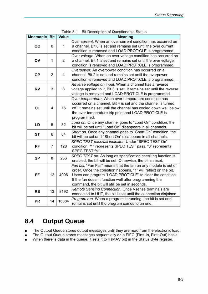
Status Reporting
8-3
Table 8-1 Bit Description of Questionable Status Mnemonic Bit Value Meaning
OC 0 1 Over current. When an over current condition has occurred on a channel, Bit 0 is set and remains set until the over current condition is removed and LOAD:PROT:CLE is programmed.
OV 1 2 Over voltage. When an over voltage condition has occurred on a channel, Bit 1 is set and remains set until the over voltage condition is removed and LOAD:PROT:CLE is programmed.
OP 2 4 Overpower. An overpower condition has occurred on a channel, Bit 2 is set and remains set until the overpower condition is removed and LOAD:PROT:CLE is programmed.
RV 3 8 Reverse voltage on input. When a channel has a reverse voltage applied to it, Bit 3 is set. It remains set until the reverse voltage is removed and LOAD:PROT:CLE is programmed.
OT 4 16
Over temperature. When over temperature condition has occurred on a channel, Bit 4 is set and the channel is turned off. It remains set until the channel has cooled down well below the over temperature trip point and LOAD:PROT:CLE is programmed.
LD 5 32 Load on. Once any channel goes to “Load On” condition, the bit will be set until “Load On” disappears in all channels.
ST 6 64 Short on. Once any channel goes to “Short On” condition, the bit will be set until “Short On” disappears in all channels.
PF 7 128 SPEC TEST pass/fail indicator. Under “SPEC TEST On” condition, “1” represents SPEC TEST pass, “0” represents SPEC TEST fail.
SP 8 256 SPEC TEST on. As long as specification checking function is enabled, the bit will be set. Otherwise, the bit is reset.
FF 12 4096
Fan fail. “Fan Fail” means that the fan on any module is out of order. Once the condition happens, “1” will reflect on the bit. Users can program “LOAD:PROT:CLE” to clear the condition. If the fan doesn’t function well after programming the command, the bit will still be set in seconds.
RS 13 8192 Remote Sensing Connection. Once Vsense terminals are connected to UUT, the bit is set until the connection disjoined.
PR 14 16384 Program run. When a program is running, the bit is set and remains set until the program comes to an end.
8.4 Output Queue The Output Queue stores output messages until they are read from the electronic load. The Output Queue stores messages sequentially on a FIFO (First-In, First-Out) basis. When there is data in the queue, it sets it to 4 (MAV bit) in the Status Byte register.
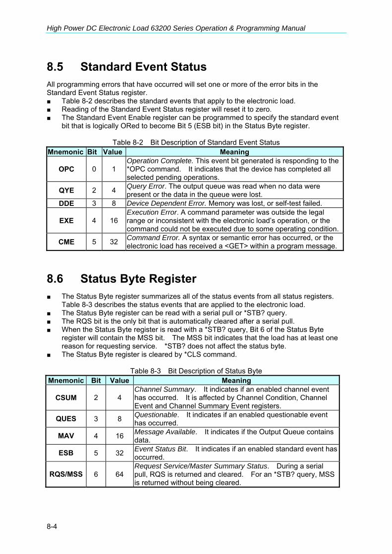
High Power DC Electronic Load 63200 Series Operation & Programming Manual
8-4
8.5 Standard Event Status All programming errors that have occurred will set one or more of the error bits in the Standard Event Status register. Table 8-2 describes the standard events that apply to the electronic load. Reading of the Standard Event Status register will reset it to zero. The Standard Event Enable register can be programmed to specify the standard event
bit that is logically ORed to become Bit 5 (ESB bit) in the Status Byte register.
Table 8-2 Bit Description of Standard Event Status Mnemonic Bit Value Meaning
OPC 0 1 Operation Complete. This event bit generated is responding to the *OPC command. It indicates that the device has completed all selected pending operations.
QYE 2 4 Query Error. The output queue was read when no data were present or the data in the queue were lost.
DDE 3 8 Device Dependent Error. Memory was lost, or self-test failed.
EXE 4 16 Execution Error. A command parameter was outside the legal range or inconsistent with the electronic load’s operation, or the command could not be executed due to some operating condition.
CME 5 32 Command Error. A syntax or semantic error has occurred, or the electronic load has received a <GET> within a program message.
8.6 Status Byte Register The Status Byte register summarizes all of the status events from all status registers.
Table 8-3 describes the status events that are applied to the electronic load. The Status Byte register can be read with a serial pull or *STB? query. The RQS bit is the only bit that is automatically cleared after a serial pull. When the Status Byte register is read with a *STB? query, Bit 6 of the Status Byte
register will contain the MSS bit. The MSS bit indicates that the load has at least one reason for requesting service. *STB? does not affect the status byte.
The Status Byte register is cleared by *CLS command.
Table 8-3 Bit Description of Status Byte Mnemonic Bit Value Meaning
CSUM 2 4 Channel Summary. It indicates if an enabled channel event has occurred. It is affected by Channel Condition, Channel Event and Channel Summary Event registers.
QUES 3 8 Questionable. It indicates if an enabled questionable event has occurred.
MAV 4 16 Message Available. It indicates if the Output Queue contains data.
ESB 5 32 Event Status Bit. It indicates if an enabled standard event has occurred.
RQS/MSS 6 64 Request Service/Master Summary Status. During a serial pull, RQS is returned and cleared. For an *STB? query, MSS is returned without being cleared.

Status Reporting
8-5
8.7 Service Request Enable Register The Service Request Enable register can be programmed to specify the bit in the Status
Byte register that will generate service requests.


Command Index
9-1
9. Command Index
9.1 Command Summary Common Commands
*CLS *ESE <NR1> *ESE? *ESR? *IDN? *OPC *OPC? *RCL <NRf> *RST *SAV <NRf> *SRE <NR1> *SRE? *STB?
Instrument Commands CONFigure
:AUTO :LOAD :MODE :DISPlay :KEY :REMote :SAVE :SOUNd :VOLTage :LATCh :RESet :ON :POLarity :RANGe :PROTection
:BATT :VOLT :Capacity? :TIME?
CROFFSET COMMunicate
:ADDRess :GPIB :RS485 :SERial :BAUD :BITS

High Power DC Electronic Load 63200 Series Operation & Programming Manual
9-2
:PARity :SBITs CURRent :STATic :L1 :L2 :RISE :FALL :DYNamic :L1 :L2 :RISE :FALL :T1 :T2 FETCh :CURRent :POWer :RESistance :VOLTAGE :STATus LOAD
[:STATe] :SHORt [:STATe] :KEY :PROTection :CLEar :SAVE
MEASure
:CURRent :INPut :POWer :RESistance :STATus
:VOLTage MODE POWer
:L1 :L2 :RISE :FALL
PROGram
:CHAin :FILE :KEY :ONTime

Command Index
9-3
:OFFTime :PF :DELay :TIME :RUN :SAVE :SEQuence :MODE :SHORt :DLEay :TIME
RESistance :L1 :L2 :RISE :FALL SPECification
:C :L :H [:PASS] :TEST :UNIT
STATus
:QUEStionable :CONDition :ENABle [:EVENt] :NTRansition
:PTRansition VOLTage
:CURRent :L1 :L2 :MODE
SYSTem :WAVE
:PARallel :DATA :DISPlay :MODE :SLAVe :CHANnel :MODEl
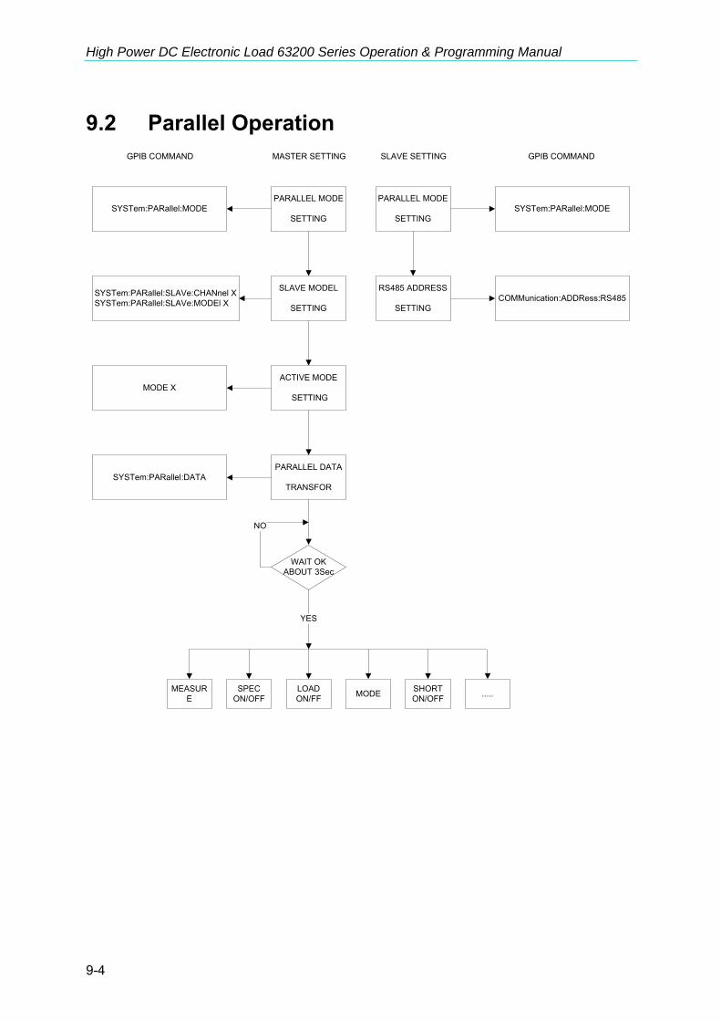
High Power DC Electronic Load 63200 Series Operation & Programming Manual
9-4
9.2 Parallel Operation
PARALLEL MODE
SETTING
PARALLEL DATA
TRANSFOR
SLAVE MODEL
SETTING
ACTIVE MODE
SETTING
MASTER SETTING
PARALLEL MODE
SETTING
RS485 ADDRESS
SETTING
SLAVE SETTING
SYSTem:PARallel:MODE
SYSTem:PARallel:SLAVe:CHANnel XSYSTem:PARallel:SLAVe:MODEl X
MODE X
SYSTem:PARallel:DATA
SYSTem:PARallel:MODE
COMMunication:ADDRess:RS485
GPIB COMMAND GPIB COMMAND
MEASURE
SPECON/OFF
LOAD ON/FF MODE SHORT
ON/OFF .....
WAIT OKABOUT 3Sec
NO
YES

Troubleshooting
10-1
10. Troubleshooting
10.1 Overview If the 632XX Series DC Electronic Load is unable to operate normally, follow the descriptions in this chapter below to troubleshoot the problems first. Please consult with Chroma’s agents or distributors if the information provided in the manual cannot solve the problem.
10.2 Troubleshooting Problems occurred during operation and suggested resolution.
Problem Cause Resolution WAIT LOAD DTR SIGNAL LOW TIMEOUT
Incorrect hardware signals (such as off line or firmware program error.)
Check if the hardware communication cable is connected correctly. Consult with Chroma’s agents or distributors if the problem still exists.
WAIT HOST DSR LOW TIMEOUT
Incorrect hardware signals (such as off line or firmware program error.)
Check if the hardware communication cable is connected correctly. Consult with Chroma’s agents or distributors if the problem still exists.


Precautions for Loading 63200 Battery
11-1
11. Precautions for Loading 63200 Battery In regard of the blooming EV, the test application for high power battery has become more and more; and the 63200 Series high power, high voltage electronics loads such as 63204 and 63210 that comply to customer’s the most. However, since it is to test the battery with high power and voltage, it is necessary to pay more attention to the application safety. According to the RMA data, the damage part is MOSFET mainly for the high power, voltage Electronic Load to be repaired in general and the most possible cause is connection over voltage between MOSFET and UUT. It maybe just a transient, but it could cause the MOSFET damaged by a little energy if it exceeds the maximum voltage. Common battery application often forms high voltage by paralleling multiple batteries to avoid the transmission lost caused by low voltage high current. As the switch is uses directly to connect the battery and applied object, the study shows it is the main cause of LOAD damage. Figure 11-1 shows the wire connection of Electronic Load & Battery. When the switch is shorted same as inputting a pulse signal, the effect caused by the stray element on the circuit (series inductance and parallel capacitance resonance) will generate a transient high voltage to damage the MOSFET and cause short circuit explosion as the simulation shows in Figure 11-2. It can see that if the battery voltage is 500Vdc, the equivalent series inductance is 10uH and the equivalent parallel capacitance is 10uF (the Load internal damping uses capacitance to parallel with the Coss of MOSFET), also when the switch is shorted, up to 911V Spike will appear which is beyond the IC maximum voltage.
Figure 11-1 Wire Connection of Electronic Load & Battery The figure below shows the simulated circuit diagram of the application that causes damage.
Battery
Switch MOSFET
+LD
-LD
R
Inductance Effect
Capacitance

High Power DC Electronic Load 63200 Series Operation & Programming Manual
11-2
t
SW1 Ls 10u R1 0
Cs 10u
VF1
R2 100m
V1 500
Figure 11-2 Simulated Circuit Diagram
T
VF1=911V
時間(s)0.00 250.00u 500.00u 750.00u 1.00m
電壓
(V)
0.00
250.00
500.00
750.00
1.00k
VF1=911V
Figure 11-3 Simulation of Surge Chart when Switching between Electronic Load & Battery
During the test procedure if the entire circuit is shorted due to MOSFET breakdown by high voltage and if the energy source is battery or other source that can provide high power, continuous high current will pass through Electronic Load internal due to short circuit. The load and the battery should be disconnected immediately. If unable to do so, the huge energy of battery output may cause the Electronic Load to burnout or even more severe situation. To prevent this from happening, a mechanism of over current protection is required. For the above situation, it is suggested not to connect the battery and Electronic Load directly using a switch only to avoid damaging the equipment.

Precautions for Loading 63200 Battery
11-3
11.1 Measures for Improvement
11.1.1 Additional Protection Switch As the burnout may expand due to the MOSFET damage and continuous energy release from battery that caused by the conditions described previously, it is suggested to connect the wires as Figure 11-4 shows below when doing the battery charge/discharge tests to prevent problems from happening and to ensure the safety of using Electronic Load.
Figure 11-4 Wire Connecting Diagram of LOAD & Battery NFB(No-Fuse Breaker): The capacity (current amount) should be smaller than maximum
current to facilitate load and it should be able to cutoff in time when the internal is aging short circuited.
R: It is suggested to install the resistor of 100kΩ or above to avoid giving Electronic Load huge voltage in a sudden.
Fuse: First calculate the kW for discharge and select a proper fuse. Note If two or more Electronic Loads are paralleled for discharge test, the front
terminal of each Load has to add a fuse for protection.
11.1.2 Operation Before inputting voltage to Electronic Load, switch to No.1 NFB to make the current go through R resistor to prevent damaging or aging the MOSFET from high voltage gave to Load internal in a sudden. Switch to No.2 NFB after 5 seconds and then start battery discharge testing. To stop discharge test, first press Load OFF on the Electronic Load and then switch No.2 NFB to OFF and last switch No.1 NFB to OFF. The whole discharge test stops and the battery is cutoff from Electronic Load. For example: How to install the wire to discharge 2kW when using 300V (maximum current is 100A) for battery discharge? (I = P / V = 2000W / 300V = 6.6A)
Battery
NFB1
NFB
R
Fus
Load
No.1 No.2

High Power DC Electronic Load 63200 Series Operation & Programming Manual
11-4
When NFB is selected, since the battery maximum current is 100A, the NFB should be smaller than 100A; therefore it is suggested to use NFB of 20A.
When R is selected, it is suggested to use the resistor of 1W, 100kΩ When Fuse is selected, it has to be larger than loading discharge current. In this case,
the discharge current is 6.6A; therefore it should use fuse of 10A.