Embed Size (px)
Citation preview

AC 2008-1363: HIGH PERFORMANCE MACHINING: A PRACTICALAPPROACH TO HIGH-SPEED MACHINING
Adrian Teo, Arizona State UniversityAdrian Teo is the owner and operator of Function7 Engineering, an aftermarket automotive partssupply company. He is both a Arizona State University staff member in the UniversityTechnology Office and a graduate student in the Mechanical and Manufacturing EngineeringTechnology Department, with an emphasis is CNC machining.
Scott Danielson, Arizona State UniversityScott Danielson is the Department Chair of the Mechanical and Manufacturing EngineeringTechnology Department at Arizona State University and has served in this capacity since 1999.He is active in ASEE and several of its Divisions, including serving as 2004-2005 Division Chairof the Mechanics Division. He serves on the Society of Manufacturing Engineers’ ManufacturingEducation and Research Community steering committee member. He is currently serving on theTechnology Accreditation Council (TAC) of ABET, representing ASME. Previously, he had beenat North Dakota State University where he was a faculty member in the Industrial andManufacturing Engineering department. His research interests include machining, effectiveteaching and engineering mechanics. Before coming to academia, he was a design engineer,maintenance supervisor, and plant engineer. He is a registered professional engineer.
Trian Georgeou, Arizona State UniversityTrian Georgeou graduated from Arizona State University (ASU) in 2003 with a Bachelor ofScience in Manufacturing Engineering Technology. He worked in industry as a MechanicalEngineer while attending graduate school, earning his Master of Science in Technology,concentration of Mechanical Engineering Technology in 2006. While in graduate school, Trianalso taught as an adjunct faculty member in Chandler Gilbert Community College’s AutomatedManufacturing Systems program. Trian worked in the aftermarket automotive industry as anengineering and design consultant for two major companies. Currently, he is a Lecturer in theASU Mechanical & Manufacturing Engineering Technology Department while remaining activein the aftermarket automotive industry.
© American Society for Engineering Education, 2008
Page 13.665.1
High Performance Machining: A Practical Approach to High-
Speed Machining
Abstract
High-speed machining (HSM) has become a popular topic in CNC machining methodology in
recent years. Simply defined, high-speed machining is a methodology to improve machining
throughput by using higher-than-normal spindle speeds coupled with extraordinarily high feed
rates without compromising the quality of the finished part. However, in practice, HSM is not a
straightforward methodology to implement. In addition to the higher spindle speeds, numerous
other factors like feed, chip loading, width and depth of cut, cutter path, tooling, machine
construction, CNC-machine controls and CAM software all impact the HSM process. Most
conventional CNC machines are equipped with a spindle with lower rpm limits (under 12,000
rpm), so the term “high performance machining” is adopted (HPM). Applying HPM
methodology requires the manufacturing engineer to possess in-depth knowledge of the limits of
the CNC machine and how to work around them. An initial investment into discovering the
limits of any CNC machine is critical to applying HSM techniques to non-specialized CNC
machines to obtain high performance machining. This paper briefly addresses the basic concepts
of HSM. Then a methodology taught at Arizona State University for systematically determining
the high performance machining envelope for a CNC machine is described. A student-
implemented case study of this methodology resulting in significant performance gains of
machining an automotive part is presented.
Introduction
Current machining methodology is largely experience-based in that much of the knowledge has
been handed-down from machinist to machinist via apprenticeships or on-the-job training. The
traditional approach to machining often has problems solved by reducing the cutting speed
and/or reducing the amount of material being cut1. This approach results in cutting parameters
that are discovered through trial and error and are typically very conservative. Even when
manufacturing education programs teach students to utilize references like Machinery’s
Handbook3, machining parameters are somewhat conservative.
Arizona State University manufacturing faculty believe it is important that manufacturing
engineers interested in machining understand high performance machining, particularly as
applied to conventional machine tools. Thus, their program teaches this content to interested
seniors and graduate students. Such knowledge enables manufacturers to improve throughput
and increase competitiveness without a significant investment in new machine tools.
Typically, high-speed machining (HSM) is achieved by using small cut depths at very high
spindle speeds (often over 20,000 RPM) and aggressive chip loads without a degragration of part
accuracy or quality2. Maintaining a light cut depth allows for high feedrates while avoiding
damage to the workpiece, spindle and cutter. A common pitfall common to first-time adopters of
Page 13.665.2
HSM methodology is the tendency to go overboard and make numerous light passes at extremely
small axial depths4. This strategy is often less efficient than taking fewer passes since the
increase in the overall toolpath length exceeds the gains from using a high feedrate.
Successful application of high-speed machining can be reduced to three key elements: the
computer-aided machining (CAM) programming, the CNC machine and tooling5. All three
elements are closely inter-related, and the right combination leads to productivity gains, cost
reduction and improved quality. It is also very easy to get the combination disastrously wrong,
generating waste very quickly via mechanisms like tool breakage or excessive chatter.
Programming is an important aspect of HSM. Toolpath and feedrate optimization allows for the
optimum cutting path to be generated in order to maximize machine throughput and productivity.
Other features like trochordial path generation minimizes tool loading while maintaining a high
cutting speed, thereby improving tool wear characteristics. The physical characteristics of the
CNC machine also play an important role in the successful application of HSM methodologies.
A well-built CNC machine has high rigidity and precision ways resistant to vibration.
With HSM, tooling becomes even more important due to number of issues. Higher speeds mean
tooling hardware must be both balanced and rigid (discussed in more depth later). Also, chip
formation from HSM processes starts to vary from traditional expectations.
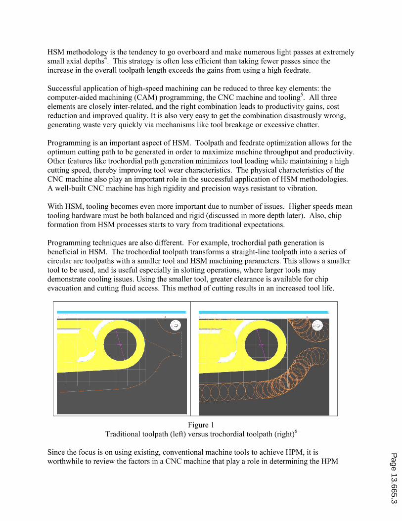
Programming techniques are also different. For example, trochordial path generation is
beneficial in HSM. The trochordial toolpath transforms a straight-line toolpath into a series of
circular arc toolpaths with a smaller tool and HSM machining parameters. This allows a smaller
tool to be used, and is useful especially in slotting operations, where larger tools may
demonstrate cooling issues. Using the smaller tool, greater clearance is available for chip
evacuation and cutting fluid access. This method of cutting results in an increased tool life.
Figure 1
Traditional toolpath (left) versus trochordial toolpath (right)6
Since the focus is on using existing, conventional machine tools to achieve HPM, it is
worthwhile to review the factors in a CNC machine that play a role in determining the HPM
Page 13.665.3
capability of the machine. This information helps manufacturing engineers judge the suitability
of their machine (or a new machine) for HPM.
The rigidity of the CNC machine affects how the machine responds to vibration. The effects of
vibration become more pronounced with HSM processes. A more rigid machine vibrates less
and improves tool life by ensuring an even chip loading, while reducing the propensity for
chatter to occur. Machine rigidity is therefore critical when applying HSM methodologies. In
short, the more rigid the machine, the better its suitability for HPM.
Typically, HSM-optimized machines use small to medium sized toolholders, and feature direct
drive spindle motors. A spindle with a smaller toolholder taper has significantly less mass than a
larger spindle. The reduced rotating mass improves the dynamics of the spindle, allowing the
CNC control system to control the spindle speed more accurately7. Similarly, direct-drive
spindles, which eliminate the use of a gearbox, improves the dynamics of the spindle and are
better suited to HPM.
Because of the higher speeds, the servo motors have to be able to keep up with the higher speeds
and loads. In addition, axial acceleration is critical during abrupt toolpath direction changes. It
is desirable that the CNC machine can achieve an axial acceleration of 1.2G to 2.0G with real-
time closed-loop positioning throughout the range of cutting speeds5.
The CNC control features conducive to applying HPM methodologies features include: high
speed program data storage, block look ahead, constant surface feed rate, automatic
acceleration/deceleration control, and high speed/high precision contouring control. The
capacity of the CNC control’s program memory needs to be large enough to cope with large
HSM-optimized programs. Running through a serial DNC/DNC2 interface becomes impractical
because the data rate required by the HSM process is much higher than the serial interface can
handle. When this occurs, the CNC machine literally “runs out of program” midway when the
program is run. Add-on storage devices like hard disks and USB flash memory act as a
secondary storage area for large programs, and allow the large programs to be run directly out of
secondary storage. Some control systems are equipped with Ethernet capability, and large
programs can be transferred back and forth to the control through the office network via standard
file transfer protocols.
Modern CNC controls come with block look ahead where the controller loads in multiple lines
(typically 30 or more lines) of CNC code ahead of the current code block being executed. The
pre-loaded blocks are preprocessed by the CNC controller, allowing it to adjust the optimum
feedrate for the projected toolpath, and eliminate inherent delays in the servo system, which
increase with higher feedrates.
Modern CNC controllers are able to automatically maintain a constant surface feedrate for a
toolpath. This feature helps HPM by maintaining a constant cutting load, improving surface
finish, tool life, and reduces the probability of tool chatter.
At high cutting rates, abrupt direction changes can cause a loss of accuracy and degradation in
surface finish5. To compensate, CNC controllers include automatic acceleration and deceleration
Page 13.665.4
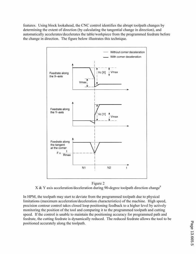
features. Using block lookahead, the CNC control identifies the abrupt toolpath changes by
determining the extent of direction (by calculating the tangential change in direction), and
automatically accelerates/decelerates the table/workpiece from the programmed feedrate before
the change in direction. The figure below illustrates this technique.
Figure 2
X & Y axis acceleration/deceleration during 90-degree toolpath direction change8
In HPM, the toolpath may start to deviate from the programmed toolpath due to physical
limitations (maximum acceleration/deceleration characteristics) of the machine. High speed,
precision contour control takes closed loop positioning feedback to a higher level by actively
monitoring the position of the tool and comparing it to the programmed toolpath and cutting
speed. If the control is unable to maintain the positioning accuracy for programmed path and
feedrate, the cutting feedrate is dynamically reduced. The reduced feedrate allows the tool to be
positioned accurately along the toolpath.
Page 13.665.5
In HPM’s higher speeds, feeds, and more aggressive cut parameters, tool wear is accelerated and
chatter is more likely to happen. Care has to be taken when mounting the tools in the toolholders
and tools must be mounted at the minimum length required for the process. Typically, carbide
tooling is ideal for HPM applications because of the increased rigidity of the cutter (resulting in
better surface finish) and longer tool life.
Well-designed, rigid toolholders are equally important in HPM applications since they form the
interface between the CNC machine’s spindle and the tool. In addition to rigidity, toolholder
balance is important. However, special, expensive toolholders are not always necessary when
doing HPM with conventional machine tools. Weldon shank toolholders should not be used
while collet toolholders, milling toolholders with a collapsible bore, shrink-fit toolholders,
hydraulic toolholders, and shell/face mill toolholders can perform well. However, shrink-fit
toolholders are expensive and hydraulic toolholders can be somewhat fragile.
High Performance Machining Adoption Methodology
A systematic approach is taught for applying HPM methodologies in order to reduce the amount
of trial-and-error required. The steps in transitioning an existing process to a HPM process are
as follows.
1. Determine the performance envelope of the CNC machine, tooling limitations, and cutting
performance baselines.
2. Evaluate current processes and identify efficiency pitfalls and potential areas where the
current process can be improved.
3. Re-write CNC code to optimize the program.
4. Perform iterative test-runs while monitoring quality, tool wear, and cycle times.
5. Finalize changes by incorporating data from the test runs into the program.
6. Optimize programs after finalization to further improve performance.
A description of these six steps as taught at Arizona State University follows. Then a case study
implemented by a student is provided.
Determining the machine tool performance envelope. The first step is to learn the limitations of
the machine and tooling. The torque and power output characteristics of the machine should be
studied using manufacturer-supplied charts. (The data and examples below are for the Fanuc
Robodrill g-T14iAL used in the case study reported later in the paper). Here the goal is to
achieve a maximum throughput for the CNC machine by making full use of the power available,
including running the machine spindle at the 10-minute high-power rating for bursts under 4
minutes (this machine has a relatively low-powered spindle motor with a low maximum rpm).
Page 13.665.6
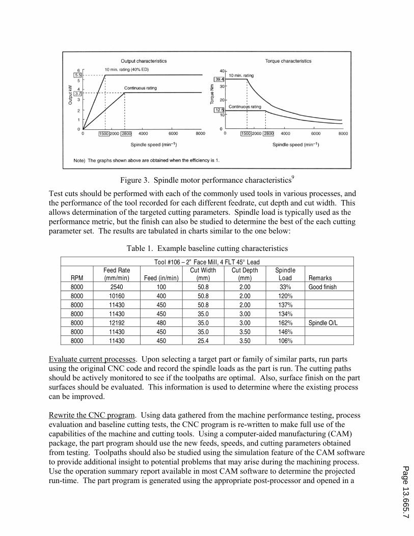
Figure 3. Spindle motor performance characteristics9
Test cuts should be performed with each of the commonly used tools in various processes, and
the performance of the tool recorded for each different feedrate, cut depth and cut width. This
allows determination of the targeted cutting parameters. Spindle load is typically used as the
performance metric, but the finish can also be studied to determine the best of the each cutting
parameter set. The results are tabulated in charts similar to the one below:
Table 1. Example baseline cutting characteristics
Tool #106 – 2” Face Mill, 4 FLT 45° Lead
RPM Feed Rate (mm/min) Feed (in/min)
Cut Width (mm)
Cut Depth (mm)
Spindle Load Remarks
8000 2540 100 50.8 2.00 33% Good finish
8000 10160 400 50.8 2.00 120%
8000 11430 450 50.8 2.00 137%
8000 11430 450 35.0 3.00 134%
8000 12192 480 35.0 3.00 162% Spindle O/L
8000 11430 450 35.0 3.50 146%
8000 11430 450 25.4 3.50 106%
Evaluate current processes. Upon selecting a target part or family of similar parts, run parts
using the original CNC code and record the spindle loads as the part is run. The cutting paths
should be actively monitored to see if the toolpaths are optimal. Also, surface finish on the part
surfaces should be evaluated. This information is used to determine where the existing process
can be improved.
Rewrite the CNC program. Using data gathered from the machine performance testing, process
evaluation and baseline cutting tests, the CNC program is re-written to make full use of the
capabilities of the machine and cutting tools. Using a computer-aided manufacturing (CAM)
package, the part program should use the new feeds, speeds, and cutting parameters obtained
from testing. Toolpaths should also be studied using the simulation feature of the CAM software
to provide additional insight to potential problems that may arise during the machining process.
Use the operation summary report available in most CAM software to determine the projected
run-time. The part program is generated using the appropriate post-processor and opened in a
Page 13.665.7
text editor for manual code cleanup. In this last step, machine specific control-commands should
be added to the program to enable HPM specific features like block look-ahead, high speed
precision control, and acceleration/deceleration control.
Perform iterative test-runs. Test runs should be made to verify the new program and the
expected productivity gains. During these test runs, the speed and feeds should be varied while
the machine load is monitored. Often the feedrate can be increased without compromising part
finish, and, conversely the feedrate may have to be lowered slightly to prevent tool chatter. Any
changes should be applied to the program with a text editor, and the process repeated on a new
part to verify the changes.
Finalize program. After the test runs are completed and programs changes verified, the CNC
program should be finalized. Documentation of the program, tooling package, and machine
parameters should be completed.
Optimize program. As with any manufacturing system, the machine and parts should be
monitored. Due to tool wear, the machine spindle motor load will progressively increase as the
tooling wears with the resulting danger of exceeding the load limit of the CNC machine. This
can be avoided by setting up an allowance (reduction) for the cutting feedrate. This parameter
allowance is determined in-process, by actively monitoring the performance of the tool during
subsequent runs of the same part.
HPM Adoption Case Study
This case study was performed on a Fanuc Robodrill gT14i-AL owned by Function7
Engineering10
. This compact CNC machine was equipped with the Fanuc 16iM-A CNC control
system with several HSM-optimized features. The control features a modest 50-block look
ahead buffer, AICC precision contour control, as well as flexible high capacity storage using
standard ATA/compact flash cards. The part family targeted was a series of aftermarket
automotive suspension arms (see Figure 4) and the goal was to increase the efficiency of part
manufacture by 50% (reduce machine time by half). The owner believed he had been aggressive
in the part programming and machining parameters in the existing processes for the part’s
manufacture.
Page 13.665.8
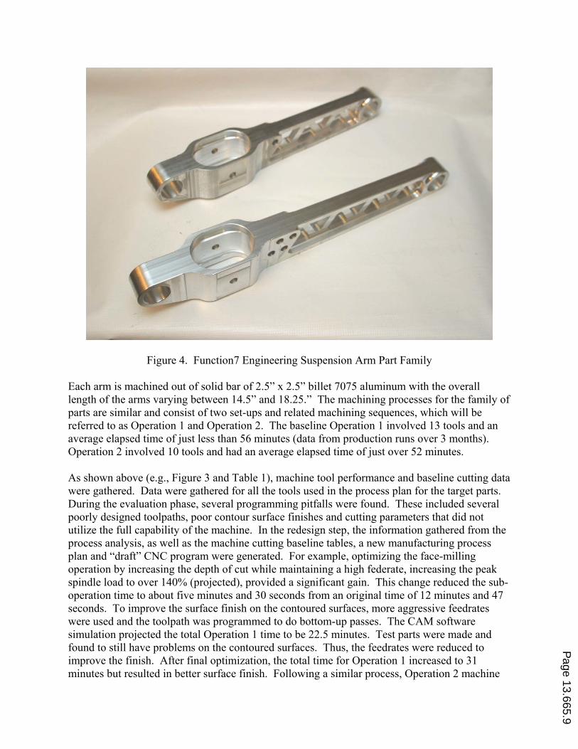
Figure 4. Function7 Engineering Suspension Arm Part Family
Each arm is machined out of solid bar of 2.5” x 2.5” billet 7075 aluminum with the overall
length of the arms varying between 14.5” and 18.25.” The machining processes for the family of
parts are similar and consist of two set-ups and related machining sequences, which will be
referred to as Operation 1 and Operation 2. The baseline Operation 1 involved 13 tools and an
average elapsed time of just less than 56 minutes (data from production runs over 3 months).
Operation 2 involved 10 tools and had an average elapsed time of just over 52 minutes.
As shown above (e.g., Figure 3 and Table 1), machine tool performance and baseline cutting data
were gathered. Data were gathered for all the tools used in the process plan for the target parts.
During the evaluation phase, several programming pitfalls were found. These included several
poorly designed toolpaths, poor contour surface finishes and cutting parameters that did not
utilize the full capability of the machine. In the redesign step, the information gathered from the
process analysis, as well as the machine cutting baseline tables, a new manufacturing process
plan and “draft” CNC program were generated. For example, optimizing the face-milling
operation by increasing the depth of cut while maintaining a high federate, increasing the peak
spindle load to over 140% (projected), provided a significant gain. This change reduced the sub-
operation time to about five minutes and 30 seconds from an original time of 12 minutes and 47
seconds. To improve the surface finish on the contoured surfaces, more aggressive feedrates
were used and the toolpath was programmed to do bottom-up passes. The CAM software
simulation projected the total Operation 1 time to be 22.5 minutes. Test parts were made and
found to still have problems on the contoured surfaces. Thus, the feedrates were reduced to
improve the finish. After final optimization, the total time for Operation 1 increased to 31
minutes but resulted in better surface finish. Following a similar process, Operation 2 machine
Page 13.665.9
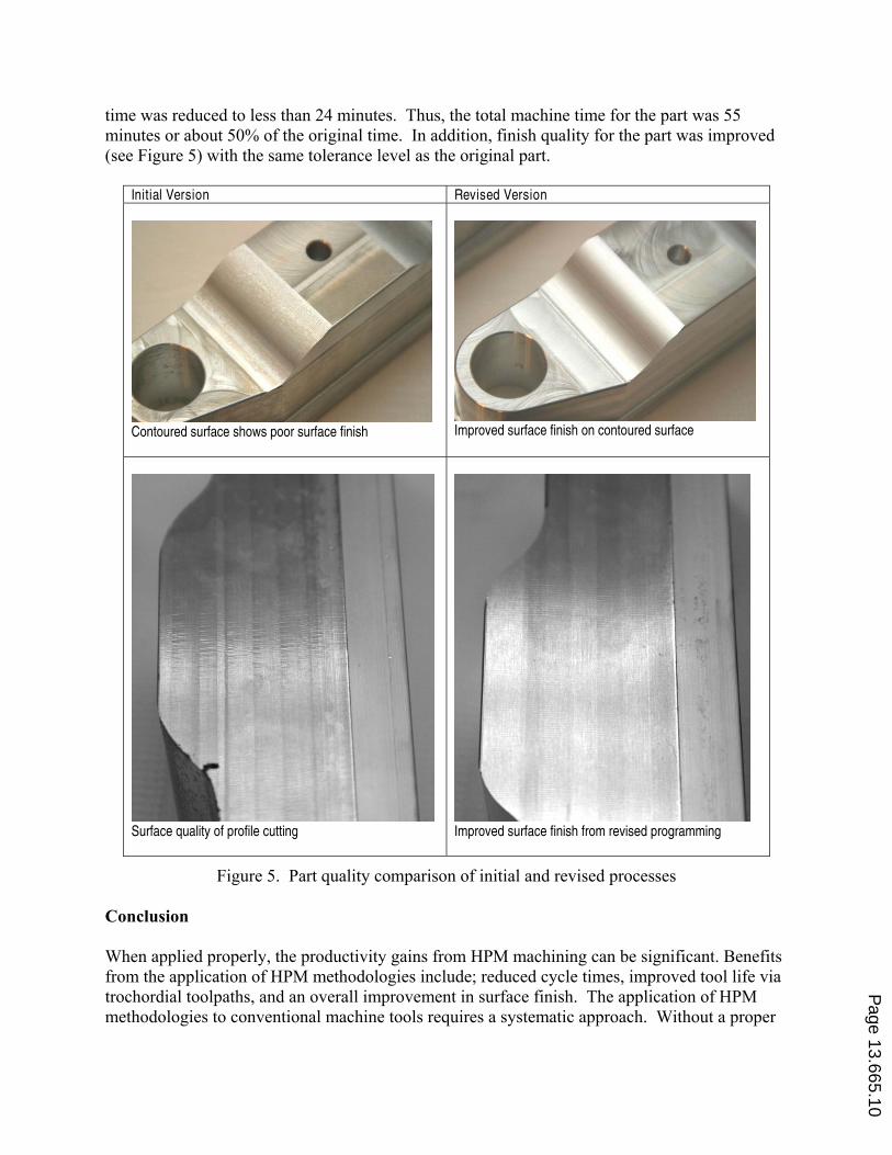
time was reduced to less than 24 minutes. Thus, the total machine time for the part was 55
minutes or about 50% of the original time. In addition, finish quality for the part was improved
(see Figure 5) with the same tolerance level as the original part.
Initial Version Revised Version
Contoured surface shows poor surface finish
Improved surface finish on contoured surface
Surface quality of profile cutting
Improved surface finish from revised programming
Figure 5. Part quality comparison of initial and revised processes
Conclusion
When applied properly, the productivity gains from HPM machining can be significant. Benefits
from the application of HPM methodologies include; reduced cycle times, improved tool life via
trochordial toolpaths, and an overall improvement in surface finish. The application of HPM
methodologies to conventional machine tools requires a systematic approach. Without a proper
Page 13.665.10
method of determining cutting capabilities to avoid a trial-and-error approach, HPM can quickly
becomes an exercise in time and material waste.
The first step in a systematic approach to implementing HPM is to determine the cutting
capabilities of the machine. This information can then be used as a cutting performance
baseline, and resulting parameters applied to the CAM programming process. After the CNC
program is generated via CAM software, further optimization is required by doing a series of test
runs.
Even for small-manufacturing runs, this approach can be applied. The performance baselines
make a very good starting point to help use the machine’s capabilities fully. A well-planned
application of HPM can see a 50% or better cycle time reduction, increasing the manufacturing
throughput by a factor of two. The time expended in applying HSM methodologies pays off
almost immediately, since the performance gains can be applied to manufacturing processes for
both existing and new parts.
Bibliography
1. Woody, B. A. & Smith, S. K. (2006). High Speed Machining Technology Basics, SME Technical Report.
2. Arone, M. (1998). High Performance Machining. Hanser Gardner Publications.
3. Oberg et al. (2004). Machinery’s Handbook, 27th Edition, Industrial Press, Inc.
4. Erdel, B. P. (2003). High Speed Machining., SME Press.
5. Mickelson, D. (2007). Guide to Hard Milling and High Speed Machining. Industrial Press, Inc.
6. Screen capture from Gibbs Cam software during Function7 Engineering case study.
7. Zenker, J. S. (1994). Getting Acquainted with High Speed Spindles. American Machinist, Nov 1994, pp 59-62.
8. Fanuc Ltd, 1997, Fanuc Series 16i/18i/160i/180i Operators Manual (B-63014EN/01). Fanuc Limited, Japan.
9. Fanuc Ltd, 1997, Fanuc Robodrill g-T14iA/ g-T14iAL/ g-T14iAS Operators Manual (B-68844EN/04). Fanuc
Limited, Japan
10. Function7 Engineering LLC. See http://www.function-7.com/products.html. Accessed January 8, 2008.
Page 13.665.11