Embed Size (px)
Citation preview
High Performance GPS Pinwheel Antenna
Waldemar Kunysz, NovAtel Inc.
BIOGRAPHY Waldemar Kunysz obtained a BSEE from the Technical University of Nova Scotia in 1989. From 1991 to 1995 he worked on phased array antennas for Microwave Landing Systems with Micronav Inc. From 1995 to the present he has been with NovAtel Inc. He has published several technical papers and proceedings articles for various conferences. His current research interests include antenna theory and design, multipath mitigation techniques, genetic algorithms and electromagnetic compatibility. ABSTRACT There is a need for improved antenna performance in view of a recent decision by the DOD to disable SA at L1 GPS channel. For single frequency receivers SA had been the main cause of the largest errors of code and carrier phase measurements. With SA turned off, the multipath, ionosphere and antenna phase center variations are now the biggest contributors to code and carrier phase measurements. Ideally the antenna must be smaller and lighter than a typical “choke ring” antenna for surveying and man pack applications. In this paper, a new high performance GPS antenna is proposed using “Pinwheel” (patent pending) technology [16], characterized by a stable phase center and very good immunity to multipath-generated replicas of GPS signal. The antenna is a fixed-beam twelve-element phased array antenna comprised of aperture-coupled spiral slots optimized to receive L1 GPS right-hand polarized signal. In addition there is an array of eleven concentric slot rings located outside the perimeter of spiral slots in order to suppress the diffraction and reflection from the edges of the antenna, and to achieve much improved right-hand circular polarization at very low elevation angles. This allows further reduction of the
predominantly left-hand polarized multipath signals generated at low elevation angles. The antenna has a very simple mechanism of establishing a proper phase gradient for all spiral slots in order to achieve right-hand polarization for the whole upper hemisphere. A spiral slot antenna element has a wide-band performance, therefore preventing unwanted phase (group delay) and amplitude modulation of the spread spectrum GPS signal typically found in narrow band antennas. In order to limit the antenna to out-of-band interference, the GPS signal is band limited with RF filters in the LNA section of the antenna. The proposed antenna is made out of a single PCB board. Another PCB board is placed underneath the antenna to act as a reflector in order to reinforce the antenna directivity and reduce the back-lobe radiation. The radiation pattern roll-off of this antenna is much sharper than the conventional GPS patch antenna. The sharp pattern roll-off allows further to reduce the antenna’s susceptibility to multipath-generated replicas of the GPS signal. The antenna does not require any alignment with respect to a given direction (such as North) due to its natural symmetry. INTRODUCTION GPS antenna requirements differ in various applications. For precise surveying applications, ideally the antenna should receive only signals above the horizon and reject all signals below the horizon plane of the antenna, have a known and stable phase center that is co-located with the geometrical center of the antenna, and have perfect circular polarization characteristics to maximize the reception of the incoming right-hand polarized (RHP) signal. A typical measure of merit of antenna polarization characteristics is Axial Ratio (AR). Front-to-back ratio is a typical measure of merit of rejecting signal below the horizon plane of the antenna. There is, of course, no
antenna that could meet all these requirements. The closest antenna that meets most of these requirements, to some degree, is a patch antenna mounted on a choke ring ground plane. Such an antenna is, however, large, bulky, heavy and relatively expensive, prohibiting its use in various applications. The new (aperture couples slot array) antenna presented in this paper is light and small and does not require a choke ring ground plane to achieve performance similar or better to a patch antenna in the choke ring ground plane configuration. Slot antennas are widely used in many practical applications such as radar and satellite communications. The main advantage of slot antennas is wider bandwidth when compared with microstrip patch antennas. The demand of ever increasing performance, miniaturization and decreasing cost in many applications requires innovative design with a high integration level of active components, circuitry, and radiating elements. While compact circuit design is best achieved on high dielectric-constant substrates, optimum performance printed antennas are built on low-permitivity substrate [6]. Two technologies have been mainly pursued, in our approach, to achieve an optimum antenna performance on medium–dielectric substrate material. One is based on micro machining technology, while the other makes use of the concept of photonic bandgap (PBG) substrates. In the first case, part of the substrate near the edges of the antenna is removed to realize a low effective dielectric-constant environment for the antenna. In this way, power losses due to surface waves are reduced and the re-radiation from the edges of the antenna is greatly reduced. The second approach relies on the concept of PBG engineering to further suppress surface wave propagation along the substrate. Several configurations have been proposed in the literature to realize PBG substrates [8], [9]. The first attempts were made by drilling a periodic pattern of holes in the substrate [3], [7]. Many antenna radiation structures suffer performance degradation due to surface wave excitation. A well-known example is the microstrip patch antenna efficiency on thick substrates [1], [2]. One of the techniques for mitigating surface waves for etched structures is to surround the item of interest with a one or two dimensional photonic crystal [4], [5] embedded in the substrate with the same height as the substrate. In our case, an array of eleven concentric slot rings was located outside the perimeter of spiral slots in order to suppress the diffraction and reflection from the edges of the antenna, and to achieve much improved right-hand circular polarization at very low elevation angles. . A flat metal sheet is used in many antennas as a reflector or ground plane [10]. The presence of a ground plane redirects one-half of the radiation into the opposite
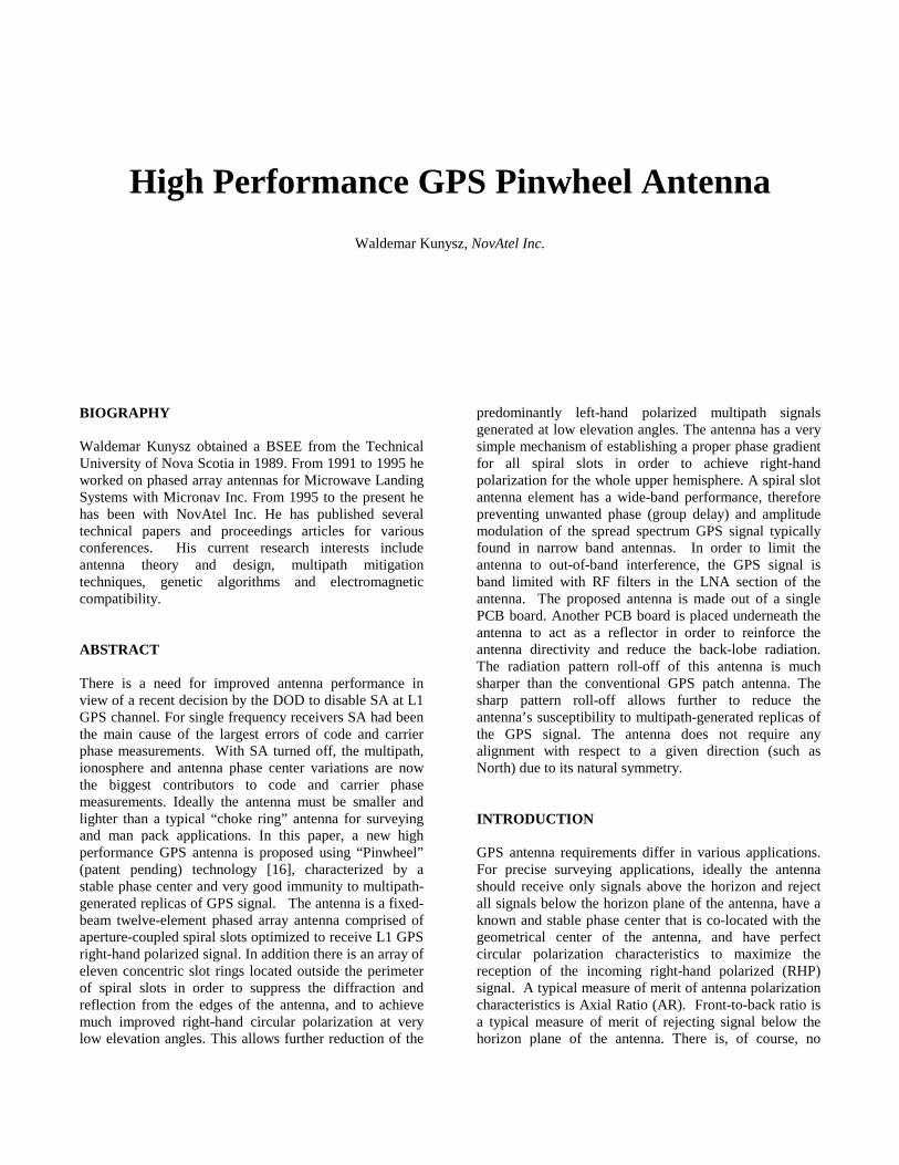
direction, improving the antenna gain and reducing the back-lobe radiation. If the antenna is too close to the conductive surface, the image currents cancel the currents in the antenna, resulting in poor radiation efficiency. In addition the metal ground plane will support surface waves [11], [12]. Surface waves will radiate vertically if scattered by bends, discontinuities (i.e. edge or a corner of the antenna ground plane), or surface texture. The concept of suppressing surface waves on metals is not new. The behaviour of surface waves on a general impedance surface is described in several textbooks [10], [11]. A corrugated metal slab [14], [15] (example: choke ring ground plane) or a metal sheet covered with small bumps [13] is examples of various geometries used to suppress surface waves on metal structures. A corrugated surface is a metal slab, with series of many (several per unit wavelength) narrow vertical slots cut down into the slab and shorted at the bottom. In most cases, the slots are quarter-wavelength deep, therefore the short circuit condition at the bottom end is transformed by the length of the slot into an open-circuit condition at the top end. The surface impedance; at the top; is therefore very high, significantly reducing the flow of any ac current. Periodic dielectric, metallic, or metal-dielectric structures that prevent the propagation of electromagnetic waves are known as photonic crystals [3]. The high impedance surface can be considered as a kind of photonic crystal that prevents the propagation of surface waves. Using high-impedance ground planes, antennas have been demonstrated that take advantage of suppressed surface waves in the form of smoother radiation pattern and with less energy radiated in the backward direction. NEW ANTENNA CONCEPT The new, patent pending, antenna is an array of multiple spiral slots that are electromagnetically coupled to a feeding network [16]. Let’s refer to it as an aperture coupled slot array antenna and denote it as a pinwheel type antenna, due to its internal layout nature. See Figure 1 for a board layout of a 12-arm spiral pinwheel antenna. This antenna is optimized for single frequency of operation, hence all spiral arms are equal in length. The spatial difference between each two consecutive spiral arms is 30°; as well the electrical phase length of the feeding network is set to 30°. This arrangement allows having a very stable phase center and achieving excellent circular polarization. The feeding network is a leaky wave microstrip circuit in order to avoid complexity, keep it simple and maintain uniform amplitude excitation for all slots.
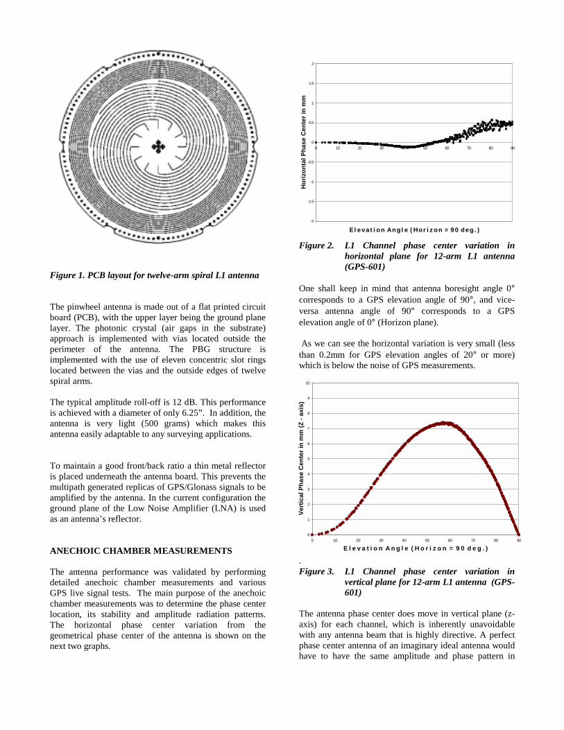
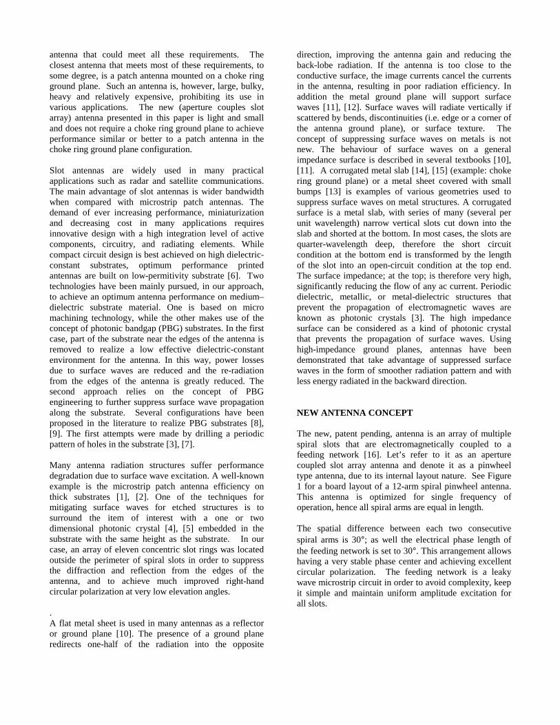
Figure 1. PCB layout for twelve-arm spiral L1 antenna The pinwheel antenna is made out of a flat printed circuit board (PCB), with the upper layer being the ground plane layer. The photonic crystal (air gaps in the substrate) approach is implemented with vias located outside the perimeter of the antenna. The PBG structure is implemented with the use of eleven concentric slot rings located between the vias and the outside edges of twelve spiral arms. The typical amplitude roll-off is 12 dB. This performance is achieved with a diameter of only 6.25”. In addition, the antenna is very light (500 grams) which makes this antenna easily adaptable to any surveying applications. To maintain a good front/back ratio a thin metal reflector is placed underneath the antenna board. This prevents the multipath generated replicas of GPS/Glonass signals to be amplified by the antenna. In the current configuration the ground plane of the Low Noise Amplifier (LNA) is used as an antenna’s reflector. ANECHOIC CHAMBER MEASUREMENTS The antenna performance was validated by performing detailed anechoic chamber measurements and various GPS live signal tests. The main purpose of the anechoic chamber measurements was to determine the phase center location, its stability and amplitude radiation patterns. The horizontal phase center variation from the geometrical phase center of the antenna is shown on the next two graphs.
Figure 2. L1 Channel phase center variation in horizontal plane for 12-arm L1 antenna (GPS-601)
One shall keep in mind that antenna boresight angle 0° corresponds to a GPS elevation angle of 90°, and vice-versa antenna angle of 90° corresponds to a GPS elevation angle of 0° (Horizon plane). As we can see the horizontal variation is very small (less than 0.2mm for GPS elevation angles of 20° or more) which is below the noise of GPS measurements.
. Figure 3. L1 Channel phase center variation in
vertical plane for 12-arm L1 antenna (GPS-601)
The antenna phase center does move in vertical plane (z-axis) for each channel, which is inherently unavoidable with any antenna beam that is highly directive. A perfect phase center antenna of an imaginary ideal antenna would have to have the same amplitude and phase pattern in
0
1
2
3
4
5
6
7
8
9
10
0 10 20 30 40 50 60 70 80 90
E l e v a t i o n A n g l e ( H o r i z o n = 9 0 d e g . )
Vert
ical
Pha
se C
ente
r in
mm
(Z -
axis
)
-2
-1.5
-1
-0.5
0
0.5
1
1.5
2
0 10 20 30 40 50 60 70 80 90
E l e v a t i o n A n g l e ( H o r i z o n = 9 0 d e g . )
Hor
izon
tal P
hase
Cen
ter i
n m
m
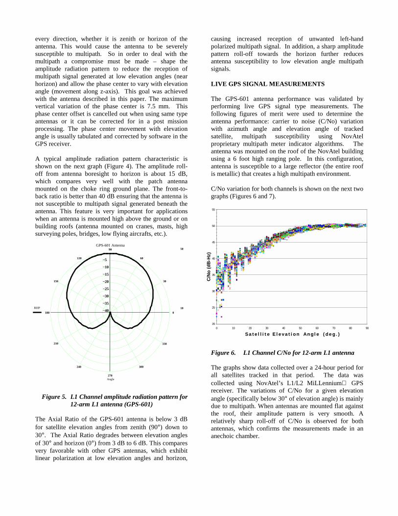
every direction, whether it is zenith or horizon of the antenna. This would cause the antenna to be severely susceptible to multipath. So in order to deal with the multipath a compromise must be made – shape the amplitude radiation pattern to reduce the reception of multipath signal generated at low elevation angles (near horizon) and allow the phase center to vary with elevation angle (movement along z-axis). This goal was achieved with the antenna described in this paper. The maximum vertical variation of the phase center is 7.5 mm. This phase center offset is cancelled out when using same type antennas or it can be corrected for in a post mission processing. The phase center movement with elevation angle is usually tabulated and corrected by software in the GPS receiver. A typical amplitude radiation pattern characteristic is shown on the next graph (Figure 4). The amplitude roll-off from antenna boresight to horizon is about 15 dB, which compares very well with the patch antenna mounted on the choke ring ground plane. The front-to-back ratio is better than 40 dB ensuring that the antenna is not susceptible to multipath signal generated beneath the antenna. This feature is very important for applications when an antenna is mounted high above the ground or on building roofs (antenna mounted on cranes, masts, high surveying poles, bridges, low flying aircrafts, etc.).
Figure 5. L1 Channel amplitude radiation pattern for
12-arm L1 antenna (GPS-601) The Axial Ratio of the GPS-601 antenna is below 3 dB for satellite elevation angles from zenith (90°) down to 30°. The Axial Ratio degrades between elevation angles of 30° and horizon (0°) from 3 dB to 6 dB. This compares very favorable with other GPS antennas, which exhibit linear polarization at low elevation angles and horizon,
causing increased reception of unwanted left-hand polarized multipath signal. In addition, a sharp amplitude pattern roll-off towards the horizon further reduces antenna susceptibility to low elevation angle multipath signals. LIVE GPS SIGNAL MEASUREMENTS The GPS-601 antenna performance was validated by performing live GPS signal type measurements. The following figures of merit were used to determine the antenna performance: carrier to noise (C/No) variation with azimuth angle and elevation angle of tracked satellite, multipath susceptibility using NovAtel proprietary multipath meter indicator algorithms. The antenna was mounted on the roof of the NovAtel building using a 6 foot high ranging pole. In this configuration, antenna is susceptible to a large reflector (the entire roof is metallic) that creates a high multipath environment. C/No variation for both channels is shown on the next two graphs (Figures 6 and 7).
Figure 6. L1 Channel C/No for 12-arm L1 antenna The graphs show data collected over a 24-hour period for all satellites tracked in that period. The data was collected using NovAtel’s L1/L2 MiLLennium GPS receiver. The variations of C/No for a given elevation angle (specifically below 30° of elevation angle) is mainly due to multipath. When antennas are mounted flat against the roof, their amplitude pattern is very smooth. A relatively sharp roll-off of C/No is observed for both antennas, which confirms the measurements made in an anechoic chamber.
0
30
60
90
120
150
180
210
240
270
300
330
GPS-601 Antenna50
10RHP
Angle
5−
10−
15−
20−
25−
30−
35−
40−
20
25
30
35
40
45
50
55
0 10 20 30 40 50 60 70 80 90
S a t e l l i t e E l e v a t i o n A n g l e ( d e g . )
C/N
o (d
B-H
z)
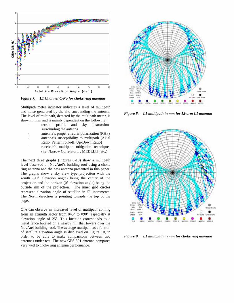
Figure 7. L1 Channel C/No for choke ring antenna Multipath meter indicator indicates a level of multipath and noise generated by the site surrounding the antenna. The level of multipath, detected by the multipath meter, is shown in mm and is mainly dependent on the following:
- terrain profile and sky obstructions surrounding the antenna
- antenna’s proper circular polarization (RHP) - antenna’s susceptibility to multipath (Axial
Ratio, Pattern roll-off, Up-Down Ratio) - receiver’s multipath mitigation techniques
(i.e. Narrow Correlator , MEDLL , etc.) The next three graphs (Figures 8-10) show a multipath level observed on NovAtel’s building roof using a choke ring antenna and the new antenna presented in this paper. The graphs show a sky view type projection with the zenith (90° elevation angle) being the center of the projection and the horizon (0° elevation angle) being the outside rim of the projection. The inner grid circles represent elevation angle of satellite in 5° increments. The North direction is pointing towards the top of the page. One can observe an increased level of multipath coming from an azimuth sector from 045° to 090°, especially at elevation angle of 25°. This location corresponds to a metal fence located on a nearby hill that towers over the NovAtel building roof. The average multipath as a funtion of satellite elevation angle is displayed on Figure 10, in order to be able to make comparisons between two antennas under test. The new GPS-601 antenna compares very well to choke ring antenna performance.
Figure 8. L1 multipath in mm for 12-arm L1 antenna
Figure 9. L1 multipath in mm for choke ring antenna
20
25
30
35
40
45
50
55
0 10 20 30 40 50 60 70 80 90
S a t e l l i t e E l e v a t i o n A n g l e ( d e g . )
C/N
o (d
B-H
z)
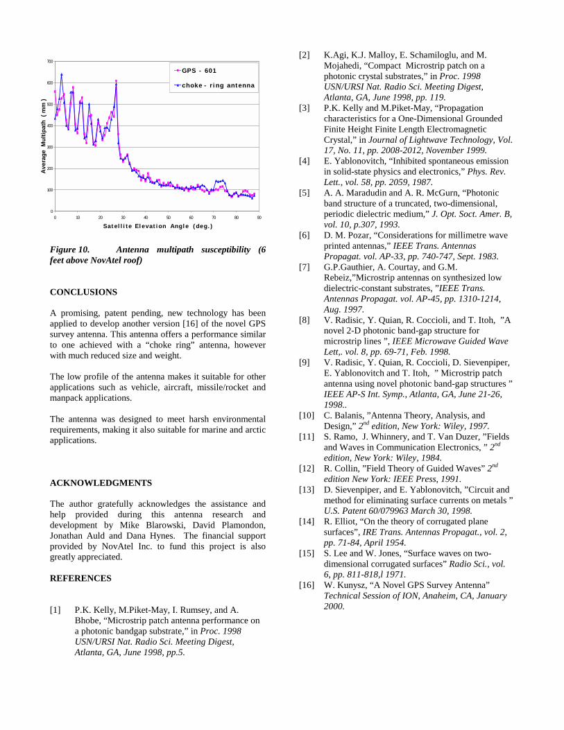
Figure 10. Antenna multipath susceptibility (6 feet above NovAtel roof) CONCLUSIONS A promising, patent pending, new technology has been applied to develop another version [16] of the novel GPS survey antenna. This antenna offers a performance similar to one achieved with a “choke ring” antenna, however with much reduced size and weight. The low profile of the antenna makes it suitable for other applications such as vehicle, aircraft, missile/rocket and manpack applications. The antenna was designed to meet harsh environmental requirements, making it also suitable for marine and arctic applications. ACKNOWLEDGMENTS The author gratefully acknowledges the assistance and help provided during this antenna research and development by Mike Blarowski, David Plamondon, Jonathan Auld and Dana Hynes. The financial support provided by NovAtel Inc. to fund this project is also greatly appreciated. REFERENCES [1] P.K. Kelly, M.Piket-May, I. Rumsey, and A.
Bhobe, “Microstrip patch antenna performance on a photonic bandgap substrate,” in Proc. 1998 USN/URSI Nat. Radio Sci. Meeting Digest, Atlanta, GA, June 1998, pp.5.
[2] K.Agi, K.J. Malloy, E. Schamiloglu, and M. Mojahedi, “Compact Microstrip patch on a photonic crystal substrates,” in Proc. 1998 USN/URSI Nat. Radio Sci. Meeting Digest, Atlanta, GA, June 1998, pp. 119.
[3] P.K. Kelly and M.Piket-May, “Propagation characteristics for a One-Dimensional Grounded Finite Height Finite Length Electromagnetic Crystal,” in Journal of Lightwave Technology, Vol. 17, No. 11, pp. 2008-2012, November 1999.
[4] E. Yablonovitch, “Inhibited spontaneous emission in solid-state physics and electronics,” Phys. Rev. Lett., vol. 58, pp. 2059, 1987.
[5] A. A. Maradudin and A. R. McGurn, “Photonic band structure of a truncated, two-dimensional, periodic dielectric medium,” J. Opt. Soct. Amer. B, vol. 10, p.307, 1993.
[6] D. M. Pozar, “Considerations for millimetre wave printed antennas,” IEEE Trans. Antennas Propagat. vol. AP-33, pp. 740-747, Sept. 1983.
[7] G.P.Gauthier, A. Courtay, and G.M. Rebeiz,”Microstrip antennas on synthesized low dielectric-constant substrates, ”IEEE Trans. Antennas Propagat. vol. AP-45, pp. 1310-1214, Aug. 1997.
[8] V. Radisic, Y. Quian, R. Coccioli, and T. Itoh, ”A novel 2-D photonic band-gap structure for microstrip lines ”, IEEE Microwave Guided Wave Lett,. vol. 8, pp. 69-71, Feb. 1998.
[9] V. Radisic, Y. Quian, R. Coccioli, D. Sievenpiper, E. Yablonovitch and T. Itoh, ” Microstrip patch antenna using novel photonic band-gap structures ” IEEE AP-S Int. Symp., Atlanta, GA, June 21-26, 1998..
[10] C. Balanis, ”Antenna Theory, Analysis, and Design,” 2nd edition, New York: Wiley, 1997.
[11] S. Ramo, J. Whinnery, and T. Van Duzer, ”Fields and Waves in Communication Electronics, ” 2nd edition, New York: Wiley, 1984.
[12] R. Collin, ”Field Theory of Guided Waves” 2nd edition New York: IEEE Press, 1991.
[13] D. Sievenpiper, and E. Yablonovitch, ”Circuit and method for eliminating surface currents on metals ” U.S. Patent 60/079963 March 30, 1998.
[14] R. Elliot, “On the theory of corrugated plane surfaces”, IRE Trans. Antennas Propagat., vol. 2, pp. 71-84, April 1954.
[15] S. Lee and W. Jones, “Surface waves on two-dimensional corrugated surfaces” Radio Sci., vol. 6, pp. 811-818,l 1971.
[16] W. Kunysz, “A Novel GPS Survey Antenna” Technical Session of ION, Anaheim, CA, January 2000.
0
100
200
300
400
500
600
700
0 10 20 30 40 50 60 70 80 90
S a t e l l i t e E l e v a t i o n A n g l e ( d e g . )
Ave
rage
Mul
tipat
h (
mm
)
G P S - 6 0 1
c h o k e - r i n g a n t e n n a