Embed Size (px)
Citation preview
HIGH PERFORMANCE CONCRETE AND DRILLED SHAFTCONSTRUCTION
Dan Brown1, Anton Schindler2
1 Dept. of Civil Engineering, Auburn University, AL 36849, 334-844-6283; email:[email protected] Dept. of Civil Engineering, Auburn University, AL 36849, 334-844-6263; email:[email protected]
ABSTRACT: Drilled shaft foundations on major bridge projects often require the use ofunderwater placement of large volumes of concrete through densely placed rebar, withthe cage often made even more congested with the placement of additional tubes for post-construction integrity testing. Such conditions represent the most difficult circumstancesfor constructors in terms of concrete placement to achieve a shaft which is free of defectsor anomalies in the integrity testing. The concept of “high performance” for drilled shaftconcrete is that the mixture should address the most critical performance requirementsrelated to workability. This paper describes the important considerations in concretemixture design for drilled shaft construction including the use of admixtures and mixturecomponents associated with self-consolidating concrete (SCC). Some case histories ofdifficulties associated with concrete are also described.
INTRODUCTION
Large diameter drilled shafts are becoming increasingly popular on major bridgeprojects due to increased availability of drilling equipment and skilled contractors andinherent advantages of high capacity shafts in supporting axial and lateral loads. Shaftdiameters of up to 4 m (13 ft) and lengths of up to 80 m (260 ft) are no longer unusual.These shafts often require the use of underwater placement of large volumes of concretethrough densely placed rebar, with the cage usually made even more congested with theplacement of additional tubes for post-construction integrity testing. Such conditionsrepresent the most difficult circumstances for constructors in terms of concrete placementto achieve a shaft which is free of defects or anomalies in the integrity testing.
This paper provides an overview of the most important characteristics of concretemixture design and construction practices for drilled shaft construction. In drilled shaftapplications, the most critical performance requirements for concrete are related toworkability and thus the concept of “high performance” material emphasizes theconstruction aspects of the mixture in addition to hardened properties required to meet
GSP 158 Contemporary Issues in Deep Foundations
structural design requirements. Important components of a good mixture design andinstallation plan include requirements for workability for the duration of the concreteplacement operations, passing ability, resistance to bleeding, and low heat of hydration.Strength requirements and aggregate properties that are consistent with theseconsiderations are important, as are concrete placement techniques used by thecontractor. If any single important issue is not adequately addressed in the mixturedesign and placement procedures, placement difficulties and/or anomalies in integrity testmeasurements can result.
WORKABILITY AND PASSING ABILITY
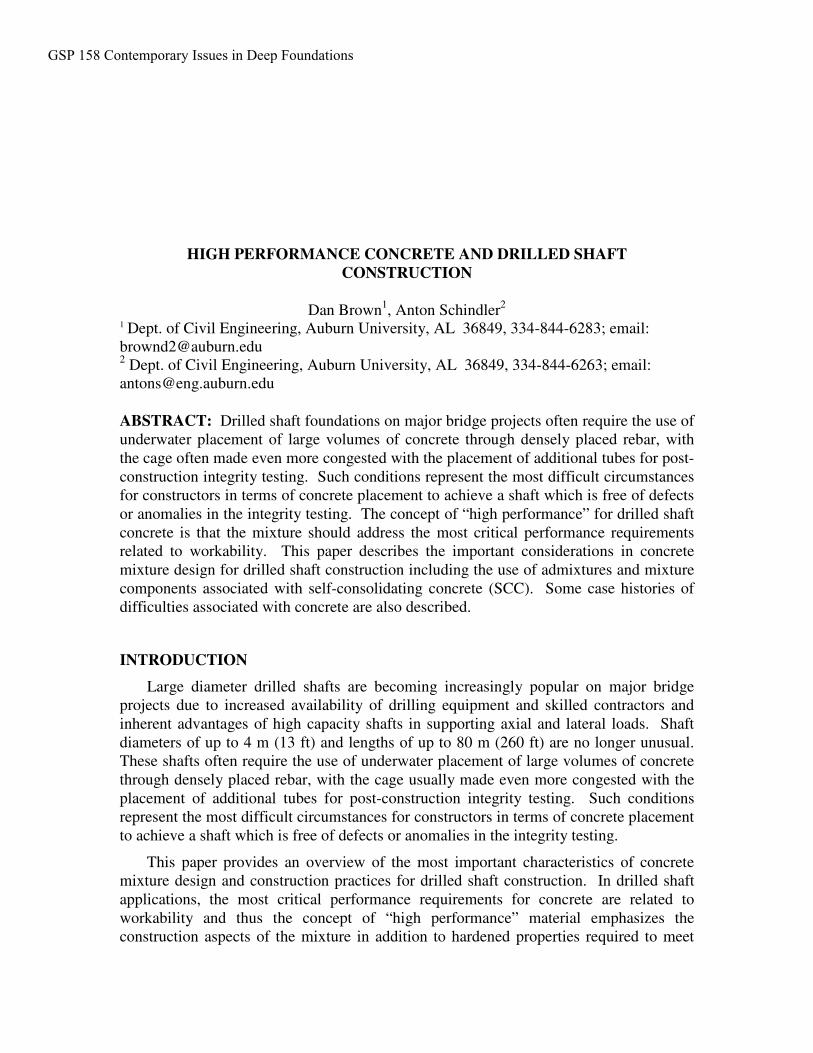
Concrete workability levels for large diameter drilled shafts must address issuesrelating to underwater placement via tremie, congested reinforcing cages, concretepumping operations, and filling ability from a single point tremie discharge into a largediameter hole. In order to flow laterally from the discharge point and fill the shaftwithout entrapment of drilling fluids or laitance from the underwater surface of the fluidconcrete, the concrete must flow smoothly through the reinforcing cage under its ownbuoyant weight without “piling up” near the tremie. A mixture with the desiredworkability will not result in more than a few inches of difference in height between thetop of the concrete surface near the tremie and the concrete on the outside of thereinforcement as shown on Figure 1.
Figure 1 Concrete Flow in Under Tremie Placement
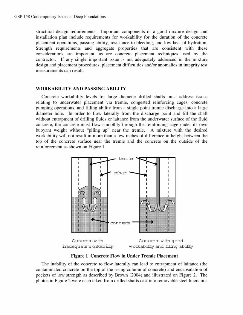
The inability of the concrete to flow laterally can lead to entrapment of laitance (thecontaminated concrete on the top of the rising column of concrete) and encapsulation ofpockets of low strength as described by Brown (2004) and illustrated on Figure 2. Thephotos in Figure 2 were each taken from drilled shafts cast into removable steel liners in a
concrete
rebar
trem ie
Concrete w ithinadequate w orkability
Concrete w ith goodw orkability and filling ability
GSP 158 Contemporary Issues in Deep Foundations
lake (left is from Texas, right is from Pennsylvania), and the soft pockets of trappedlaitance were exposed upon removal of the form. Yao and Gerwick (2004) describe thedesirability of underwater concrete to flow laterally in a “bulged” flow pattern with arelatively flat, smooth top surface rather than as a “layered” flow pattern which can resultin steeply sloped and rugged top surface that increase the exposure of concrete surfaces towater.
Figure 2 Exposure of Trapped Laitance Attributed to Inadequate Workability
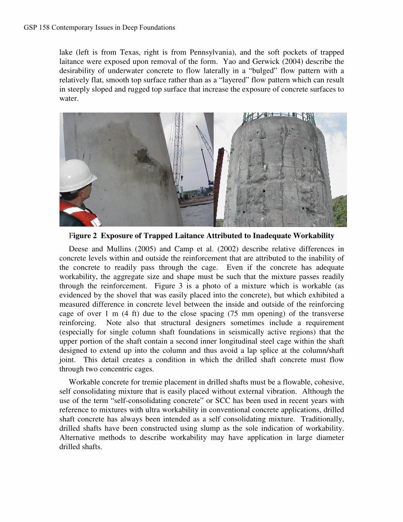
Deese and Mullins (2005) and Camp et al. (2002) describe relative differences inconcrete levels within and outside the reinforcement that are attributed to the inability ofthe concrete to readily pass through the cage. Even if the concrete has adequateworkability, the aggregate size and shape must be such that the mixture passes readilythrough the reinforcement. Figure 3 is a photo of a mixture which is workable (asevidenced by the shovel that was easily placed into the concrete), but which exhibited ameasured difference in concrete level between the inside and outside of the reinforcingcage of over 1 m (4 ft) due to the close spacing (75 mm opening) of the transversereinforcing. Note also that structural designers sometimes include a requirement(especially for single column shaft foundations in seismically active regions) that theupper portion of the shaft contain a second inner longitudinal steel cage within the shaftdesigned to extend up into the column and thus avoid a lap splice at the column/shaftjoint. This detail creates a condition in which the drilled shaft concrete must flowthrough two concentric cages.
Workable concrete for tremie placement in drilled shafts must be a flowable, cohesive,self consolidating mixture that is easily placed without external vibration. Although theuse of the term “self-consolidating concrete” or SCC has been used in recent years withreference to mixtures with ultra workability in conventional concrete applications, drilledshaft concrete has always been intended as a self consolidating mixture. Traditionally,drilled shafts have been constructed using slump as the sole indication of workability.Alternative methods to describe workability may have application in large diameterdrilled shafts.
GSP 158 Contemporary Issues in Deep Foundations
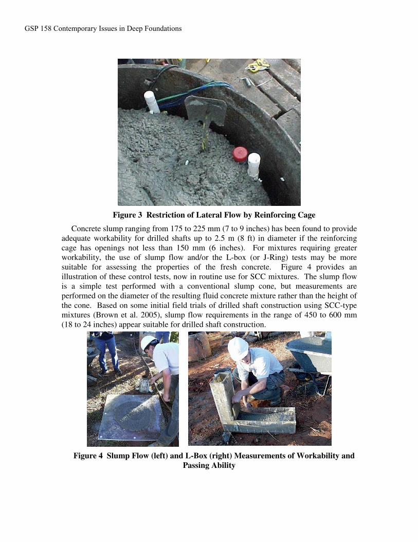
Figure 3 Restriction of Lateral Flow by Reinforcing Cage
Concrete slump ranging from 175 to 225 mm (7 to 9 inches) has been found to provideadequate workability for drilled shafts up to 2.5 m (8 ft) in diameter if the reinforcingcage has openings not less than 150 mm (6 inches). For mixtures requiring greaterworkability, the use of slump flow and/or the L-box (or J-Ring) tests may be moresuitable for assessing the properties of the fresh concrete. Figure 4 provides anillustration of these control tests, now in routine use for SCC mixtures. The slump flowis a simple test performed with a conventional slump cone, but measurements areperformed on the diameter of the resulting fluid concrete mixture rather than the height ofthe cone. Based on some initial field trials of drilled shaft construction using SCC-typemixtures (Brown et al. 2005), slump flow requirements in the range of 450 to 600 mm(18 to 24 inches) appear suitable for drilled shaft construction.
Figure 4 Slump Flow (left) and L-Box (right) Measurements of Workability andPassing Ability
GSP 158 Contemporary Issues in Deep Foundations
Concrete mixtures can be designed with high workability by using suitable aggregatesand gradation and the proper dosage of water reducing admixtures. Some of the keycomponents for high workability drilled shaft mixtures are as follows:• Rounded gravel aggregate sources are much preferred over crushed stone in these
mixtures. Coarse aggregates with a No. 67 or No. 78 gradation have performedbetter than a No. 57 in terms of workability.
• In general, an increase in the sand content in proportion to coarse aggregate willprovide increased workability and passing ability with less tendency for segregation; a sand to total aggregate ratio (by volume) from 0.44 to 0.50 has beenfound to work well in drilled shaft mixtures.
• Water reducing admixtures in current use, include polycarboxylate-basedmaterials. Many contractors have a reluctance to use “super plasticizers” as theyare sometimes called because of experiences with flash set. However, these badexperiences were typically encountered with the older naphthalene-based waterreducers and given the wide range of newer products available nowadays, a waterreducer combined with proper hydration control admixtures can extend theworkability as needed for practically all drilled shaft applications. It must be notedthat hydration control is highly temperature dependent, as will be discussedsubsequently.
WORKABILITY RETENTION
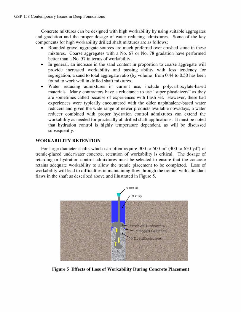
For large diameter shafts which can often require 300 to 500 m3 (400 to 650 yd3) oftremie-placed underwater concrete, retention of workability is critical. The dosage ofretarding or hydration control admixtures must be selected to ensure that the concreteretains adequate workability to allow the tremie placement to be completed. Loss ofworkability will lead to difficulties in maintaining flow through the tremie, with attendantflaws in the shaft as described above and illustrated in Figure 5.
Figure 5 Effects of Loss of Workability During Concrete Placement
Fresh,fluid concrete
Trapped Laittance
O ld,stiffconcrete
Trem ie
Slurry
GSP 158 Contemporary Issues in Deep Foundations
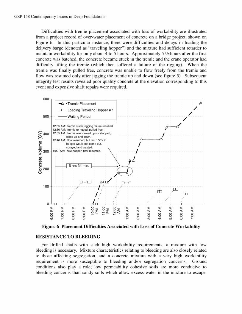
Difficulties with tremie placement associated with loss of workability are illustratedfrom a project record of over-water placement of concrete on a bridge project, shown onFigure 6. In this particular instance, there were difficulties and delays in loading thedelivery barge (denoted as “traveling hopper”) and the mixture had sufficient retarder tomaintain workability for only about 4 to 5 hours. Approximately 5 ½ hours after the firstconcrete was batched, the concrete became stuck in the tremie and the crane operator haddifficulty lifting the tremie (which then suffered a failure of the rigging). When thetremie was finally pulled free, concrete was unable to flow freely from the tremie andflow was resumed only after jigging the tremie up and down (see figure 5). Subsequentintegrity test results revealed poor quality concrete at the elevation corresponding to thisevent and expensive shaft repairs were required.
Figure 6 Placement Difficulties Associated with Loss of Concrete Workability
RESISTANCE TO BLEEDING
For drilled shafts with such high workability requirements, a mixture with lowbleeding is necessary. Mixture characteristics relating to bleeding are also closely relatedto those affecting segregation, and a concrete mixture with a very high workabilityrequirement is more susceptible to bleeding and/or segregation concerns. Groundconditions also play a role; low permeability cohesive soils are more conducive tobleeding concerns than sandy soils which allow excess water in the mixture to escape.
0
100
200
300
400
500
600
6:00
PM
7:00
PM
8:00
PM
9:00
PM
10:0
0P
M
11:0
0P
M
12:0
0A
M
1:00
AM
2:00
AM
3:00
AM
4:00
AM
5:00
AM
6:00
AM
7:00
AM
Con
cret
eV
olum
e(C
Y)
Tremie Placement
Loading Traveling Hopper # 1
Waiting Period
12:05 AM: tremie stuck, rigging failure resulted12:30 AM: tremie re-rigged, pulled free.12:35 AM: tremie over-flowed , pour stopped,
cable up and down.12:40 AM: flow resumed, but last 10CY in
hopper would not come out,sprayed and wasted.
1:00 AM: new hopper, flow resumed.
5 hrs 34 min.
GSP 158 Contemporary Issues in Deep Foundations
The worst conditions for bleeding occur when there is a long steel casing that preventsexcess water in the concrete from escaping into the surrounding soil.
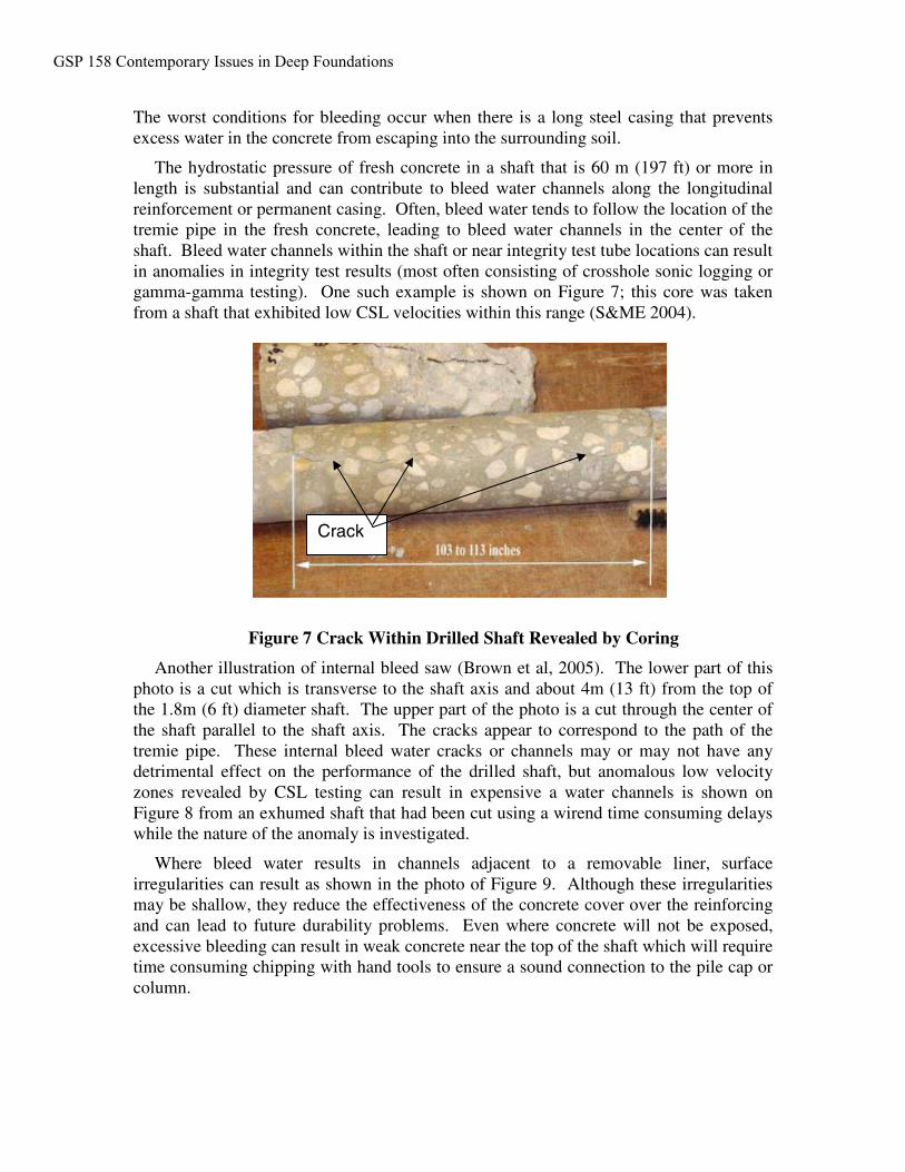
The hydrostatic pressure of fresh concrete in a shaft that is 60 m (197 ft) or more inlength is substantial and can contribute to bleed water channels along the longitudinalreinforcement or permanent casing. Often, bleed water tends to follow the location of thetremie pipe in the fresh concrete, leading to bleed water channels in the center of theshaft. Bleed water channels within the shaft or near integrity test tube locations can resultin anomalies in integrity test results (most often consisting of crosshole sonic logging orgamma-gamma testing). One such example is shown on Figure 7; this core was takenfrom a shaft that exhibited low CSL velocities within this range (S&ME 2004).
Figure 7 Crack Within Drilled Shaft Revealed by Coring
Another illustration of internal bleed saw (Brown et al, 2005). The lower part of thisphoto is a cut which is transverse to the shaft axis and about 4m (13 ft) from the top ofthe 1.8m (6 ft) diameter shaft. The upper part of the photo is a cut through the center ofthe shaft parallel to the shaft axis. The cracks appear to correspond to the path of thetremie pipe. These internal bleed water cracks or channels may or may not have anydetrimental effect on the performance of the drilled shaft, but anomalous low velocityzones revealed by CSL testing can result in expensive a water channels is shown onFigure 8 from an exhumed shaft that had been cut using a wirend time consuming delayswhile the nature of the anomaly is investigated.
Where bleed water results in channels adjacent to a removable liner, surfaceirregularities can result as shown in the photo of Figure 9. Although these irregularitiesmay be shallow, they reduce the effectiveness of the concrete cover over the reinforcingand can lead to future durability problems. Even where concrete will not be exposed,excessive bleeding can result in weak concrete near the top of the shaft which will requiretime consuming chipping with hand tools to ensure a sound connection to the pile cap orcolumn.
Crack
GSP 158 Contemporary Issues in Deep Foundations
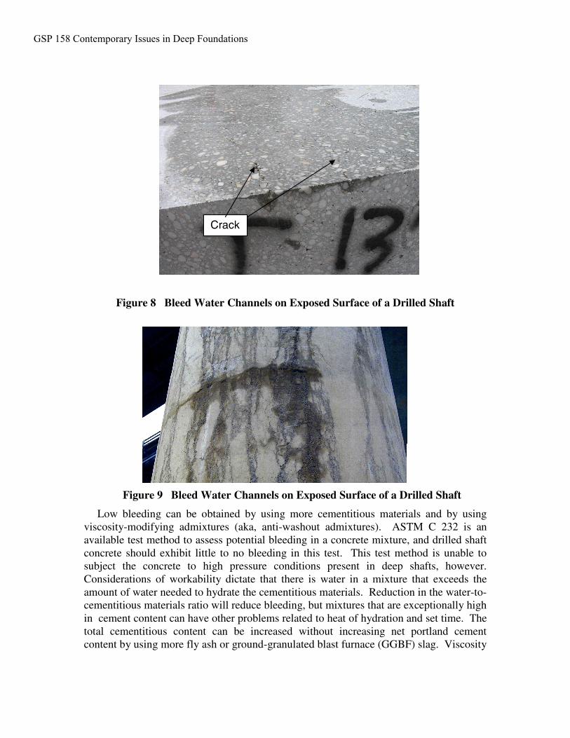
Figure 8 Bleed Water Channels on Exposed Surface of a Drilled Shaft
Figure 9 Bleed Water Channels on Exposed Surface of a Drilled Shaft
Low bleeding can be obtained by using more cementitious materials and by usingviscosity-modifying admixtures (aka, anti-washout admixtures). ASTM C 232 is anavailable test method to assess potential bleeding in a concrete mixture, and drilled shaftconcrete should exhibit little to no bleeding in this test. This test method is unable tosubject the concrete to high pressure conditions present in deep shafts, however.Considerations of workability dictate that there is water in a mixture that exceeds theamount of water needed to hydrate the cementitious materials. Reduction in the water-to-cementitious materials ratio will reduce bleeding, but mixtures that are exceptionally highin cement content can have other problems related to heat of hydration and set time. Thetotal cementitious content can be increased without increasing net portland cementcontent by using more fly ash or ground-granulated blast furnace (GGBF) slag. Viscosity
Crack
GSP 158 Contemporary Issues in Deep Foundations
modifying admixtures (VMA) can be effective at binding up free water prior to setting ofthe concrete.
When high dosages of fly ash or GGBF slag are used, the strength development willbe slower when compared to mixtures with only portland cement. However, when cured,these mixtures may exhibit higher long-term strengths. In these cases it is advisable totest the specified compressive strength at 56 or 91 days in lieu of the normal 28 dayspecified strength for conventional concrete.
CONTROL OF TEMPERATURE
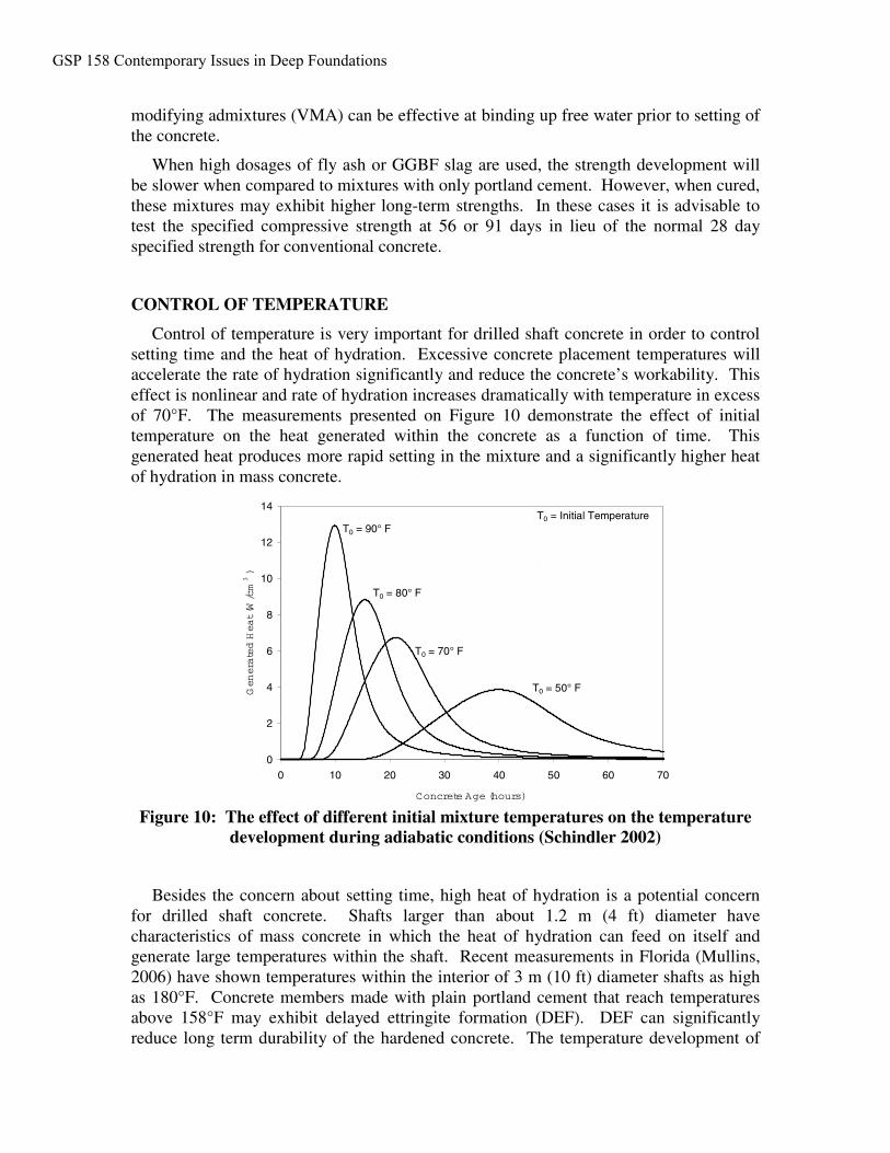
Control of temperature is very important for drilled shaft concrete in order to controlsetting time and the heat of hydration. Excessive concrete placement temperatures willaccelerate the rate of hydration significantly and reduce the concrete’s workability. Thiseffect is nonlinear and rate of hydration increases dramatically with temperature in excessof 70°F. The measurements presented on Figure 10 demonstrate the effect of initialtemperature on the heat generated within the concrete as a function of time. Thisgenerated heat produces more rapid setting in the mixture and a significantly higher heatof hydration in mass concrete.
Figure 10: The effect of different initial mixture temperatures on the temperaturedevelopment during adiabatic conditions (Schindler 2002)
Besides the concern about setting time, high heat of hydration is a potential concernfor drilled shaft concrete. Shafts larger than about 1.2 m (4 ft) diameter havecharacteristics of mass concrete in which the heat of hydration can feed on itself andgenerate large temperatures within the shaft. Recent measurements in Florida (Mullins,2006) have shown temperatures within the interior of 3 m (10 ft) diameter shafts as highas 180°F. Concrete members made with plain portland cement that reach temperaturesabove 158°F may exhibit delayed ettringite formation (DEF). DEF can significantlyreduce long term durability of the hardened concrete. The temperature development of
τ = 28.0 hrsβ = 1.50αu = 0.850
0
2
4
6
8
10
12
14
0 10 20 30 40 50 60 70
Concrete Age (hours)
Generated
Heat(W
/cm
3)
T0 = 90° FT0 = Initial Temperature
T0 = 80° F
T0 = 70° F
T0 = 50° F
GSP 158 Contemporary Issues in Deep Foundations
an in-place mixture within an actual shaft can be evaluated on test specimens by usingadiabatic or semi-adiabatic calortimery (Schindler and Folliard 2005).
In-place temperatures can be controlled by: 1) limiting the total cementitious materialscontent , 2) controlling the fresh concrete placement temperature, and 3) proper selectionof the cementitious material types.
The amount of total cementitious materials has implications relative to designcompressive strength. However, concrete design stresses are often quite low in drilledshafts and so it is prudent that the mixture design requirements not exceed the actualperformance requirements for design. Because of concerns for setting time and heat ofhydration, the use additional portland cement to accommodate an unnecessarily highstrength requirement can have other implications on mixture performance. When itcomes to cement content, more is not always better!
The data from Figure 10 demonstrate the benefits of controlling the fresh concreteplacement temperature in terms of controlling heat of hydration. Temperature controls atthe batch plant can be achieved by substituting some of the mixing water with ice, or withliquid nitrogen thermal probes that are used to cool the concrete in the truck.
The use of Type II cement and high dosages of either Class F fly ash or GGBF slagare often the best options to control heat of hydration. Concrete mixtures with highdosages of fly ash or GGBF slag will tend to generate less heat of hydration and are alsoless prone to DEF; temperatures up to about 178°F can be tolerated without significantconcerns of DEF.
SUMMARY
Drilled shaft concrete for large diameter shafts requires careful consideration of thespecial concrete requirements for this application. The authors propose that the conceptof “high performance concrete” should be applied to drilled shaft mixtures to incorporatecritical performance requirements related to workability. Specific performancerequirements that are particular to drilled shaft applications are described, includingworkability for the duration of the placement operation, passing ability, resistance tobleeding, and low heat of hydration. Some of these requirements have commoncharacteristics with those associated with “self-consolidating concrete” or SCC, but manyare specific to drilled shaft applications. This paper has included an overview of manystrategies that might be employed to achieve a concrete mixture that is well-suited todrilled shafts, including:
• Use rounded gravel aggregates rather than crushed stone• Use No. 67 or 78 aggregate gradation rather than No. 57• Use sand to total aggregate ratio in the range of 0.44 to 0.50• Use water reducing and hydration control admixtures• Use fly ash and/or slag to increase cementitious materials content and reduce
the portland cement content• Use 56 day or 90 day strength specifications in lieu of 28 day for concretes
with high dosage of fly ash or GGBF slag• Use viscosity modifying admixtures (VMA) as needed to help control bleeding
GSP 158 Contemporary Issues in Deep Foundations
• Consider the temperature of the mixture when selecting admixture dosages tomeet workability requirements and delay setting time and use adiabatic orsemi-adiabatic curing of specimens to evaluate temperature development of in-place mixtures
• Control the fresh concrete placement temperature to less than 80°F (andpreferably 75°F)
• Utilize Type II cement along with fly ash or slag to control heat of hydrationand reduce potential for delayed ettringite formation
Of course these suggestions are general guidelines with varying degrees of relevanceto each specific project. Perhaps the most important guideline is that each drilled shaftproject should have a specific mixture developed to meet the requirements for thatproject. Fresh concrete performance grades, as proposed for hardened properties(Goodspeed, Vanikar, and Cook 1996) should be established for drilled shaft concretes.By preselecting the required performance grade for each fresh property, this will enabledesigners, contactors, and concrete suppliers to communicate the specific uniquerequirements of the concrete placement before bidding of the project costs. A singlemixture design cannot be simply transferred from one locale to another withoutconsideration of the specific source materials and project requirements.
ACKNOWLEDGEMENTS
The authors gratefully acknowledge the contributions of Joe Bailey of AppliedFoundation Testing, Prof. Gray Mullins of the Univ. of S. Florida, Billy Camp and AaronGoldberg of S&ME, Charleston, Jeff Sizemore of SCDOT, Mark McClelland ofTXDOT, and Steve Dapp of Dan Brown & Associates.
REFERENCES
Brown, D., (2004). “Zen and the Art of Drilled Shaft Construction,” GeoSupport 2004,ASCE, GSP 124, pp. 19-33.
Brown, D., Bailey, J., and Schindler, A. (2005). “The Use of Self-ConsolidatingConcrete for Drilled Shaft Construction: Preliminary Observations from the LumberRiver Bridge Field Trials,” Proc, Geo Construction QA/ QC Conf, ADSC: The Int’lAssoc. of Foundation Drilling, Dallas/Ft. Worth, TX, pp. 437-448.
Camp, W., Brown, D., and Mayne, P. (2002). “Construction Method Effects on AxialDrilled Shaft Performance,” Deep Foundations 2002, ASCE, GSP 116, pp 193-208.
Deese, G., and Mullins, G. (2005). “Factors Affecting Concrete Flow in Drilled ShaftConstruction, ” Proceedings, Geo Construction Quality Assurance / Quality ControlConference, ADSC: The International Association of Foundation Drilling, Dallas/Ft.Worth, TX, pp. 144-155.
F&ME Consultants (2004). “Report of Drilled Shaft Coring” Unpubl Report to SCDOT
Goodspeed, C.H., Vanikar, S., and Cook, R.A. (1996). “High-Performance ConcreteDefined for Highway Structures,” Concrete International, Vol. 18, No. 2, pp. 62-67.
GSP 158 Contemporary Issues in Deep Foundations
Holland, T. and Gerwick, B. (1983). “Cracking of Mass Concrete Placed Under Water,” Concrete International, April, pp. 29-36.
Mullins, G. (2006). Personal communication.
Schindler, A.K. (2002). “Concrete Hydration, Temperature Development, and Setting atEarly-Ages,” Ph.D. Dissertation, The University of Texas at Austin, Texas.
Schindler A.K., and Folliard K.J. (2005). “Heat of hydration models for cementitiousmaterials,” ACI Materials Journal, Vol. 102, No. 1, 2005, pp. 24-33.
Yao, S. and Gerwick, B. (2004). “Underwater Concrete,” Concrete Int’l, Feb., pp. 77-82.
GSP 158 Contemporary Issues in Deep Foundations