Embed Size (px)
Citation preview

High-Level ETL for Semantic DataWarehouses—Full Version1
Rudra Pratap Deb Nath a,b,*, Oscar Romero b, Torben Bach Pedersen a and Katja Hose a
a Department of Computer Science, Aalborg University, DenmarkE-mail: {rudra,tbp,khose}@cs.aau.dkb Department of Service and Information System Engineering, Universitat PolitÃlcnica de Catalunya, SpainE-mail: {rudra,oromero}@essi.upc.edu
Abstract. The popularity of the Semantic Web (SW) encourages organizations to organize and publish semantic data usingthe RDF model. This growth poses new requirements to Business Intelligence (BI) technologies to enable On-Line AnalyticalProcessing (OLAP)-like analysis over semantic data. The incorporation of semantic data into a Data Warehouse (DW) is notsupported by the traditional Extract-Transform-Load (ETL) tools because they do not consider semantic issues in the integrationprocess. In this paper, we propose a layer-based integration process and a set of high-level RDF-based ETL constructs requiredto define, map, extract, process, transform, integrate, update, and load (multidimensional) semantic data. Different to other ETLtools, we automate the ETL data flows by creating metadata at the schema level. Therefore, it relieves ETL developers from theburden of manual mapping at the ETL operation level. We create a prototype, named Semantic ETL Construct (SETLCONSTRUCT),based on the innovative ETL constructs proposed here. To evaluate SETLCONSTRUCT, we create a multidimensional semantic DWby integrating a Danish Business dataset and an EU Subsidy dataset using it and compare it with the previous programmableframework SETLPROG in terms of productivity, development time and performance. The evaluation shows that 1) SETLCONSTRUCT
uses 92% fewer Number of Typed Characters (NOTC) than SETLPROG, and SETLAUTO (the extension of SETLCONSTRUCT forgenerating ETL execution flow automatically) further reduces the Number of Used Concepts (NOUC) by another 25%; 2) usingSETLCONSTRUCT, the development time is almost cut in half compared to SETLPROG, and is cut by another 27% using SETLAUTO;3) SETLCONSTRUCT is scalable and has similar performance compared to SETLPROG.
Keywords: RDF, Layer-based Semantic Data Integration, ETL constructs, Semantic ETL, Semantic Data Warehosue
1. Introduction
Semantic Web technologies enable adding a seman-tic layer over the data; thus, the data can be pro-cessed and effectively retrieved by both humans andmachines. The Linked Data (LD) principles are theset of standard rules to publish and connect data us-ing semantic links [1]. With the growing popularityof the SW and LD, more and more organizations na-tively manage data using SW standards, such as Re-source Description Framework (RDF), RDF-Schema(RDFs), the Web Ontology Language (OWL), etc. [2].Moreover, one can easily convert data given in an-
1This journal paper is submitted to Semantic Web âAS Interop-erability, Usability, Applicability an IOS Press Journal
*Corresponding author. E-mail: [email protected].
other format (database, XML, JSON, etc.) into RDFformat using an RDF wrapper. As a result, a lot ofsemantic datasets are now available in different dataportals, such as DataHub2, Linked Open Data Cloud 3
(LOD), etc. Most SW data provided by internationaland governmental organizations include facts and fig-ures, which give rise to new requirements for BusinessIntelligence (BI) tools to enable analyses in the style ofOnline Analytical Processing (OLAP) over those se-mantic data [3].
OLAP is a well-recognized technology to supportdecision making by analyzing data integrated frommultiple sources. The integrated data are stored in aData Warehouse (DW), typically structured follow-
2https://datahub.io/3https://lod-cloud.net/
arX
iv:2
006.
0718
0v1
[cs
.DB
] 1
2 Ju
n 20
20

ing the Multidimensional Model (MD) that representsdata in terms of facts and dimensions to enable OLAPqueries. The integration process for extracting datafrom different sources, translating it according to theunderlying semantics of the DW, and loading it into theDW is known as Extract-Transform-Load (ETL). Oneway to enable OLAP analysis over semantic data is byextracting those data and translating them according tothe DW’s format using a traditional ETL process. [4]outlines such a type of semi-automatic method to inte-grate semantic data into a traditional RDBMS-centricMD DW. However, the process does not maintain allthe semantics of data as they are conveying in the se-mantic sources; hence the integrated data no more fol-low the SW data principles defined in [5]. The se-mantics of the data in a semantic data source is de-fined by 1) using Internationalized Resource Identi-fier (IRIs) to uniquely identify resources globally, 2)providing common terminology, 3) semantically link-ing with published information, and 4) providing fur-ther knowledge (e.g., logical axioms) to allow reason-ing [6].
Therefore, considering semantic issues in the inte-gration process should be emphasized. Moreover, ini-tiatives such as Open Government Data4 encourage or-ganizations to publish their data using standards andnon-proprietary formats [7]. The integration of seman-tic data into a DW raises the challenges of schemaderivation, semantic heterogeneity, semantic annota-tion, linking as well as the schema and data man-agement system over traditional DW technologies andETL tools. The main drawback of a state-of-the-artRelational Database Management System (RDBMS)-based DW is that it is strictly schema dependent andless flexible to evolving business requirements. Tocover new business requirements, every step of thedevelopment cycle needs to be updated to cope withthe new requirements. This update process is time-consuming as well as costly and is sometimes not ad-justable with the current setup of the DW; hence it in-troduces the need for a novel approach. The limita-tions of traditional ETL tools to process semantic datasources are: (1) they do not fully support semantic-aware data, (2) they are entirely schema dependent(i.e., cannot handle data expressed without pre-definedschema), (3) they do not focus on meaningful semanticrelationships to integrate data from disparate sources,and (4) they neither support to capture the semantics
4https://opengovdata.org/
of data nor support to derive new information by activeinference and reasoning on the data.
Semantic Web technologies address the problemsdescribed above, as they allow adding semantics atboth data and schema level in the integration processand publish data in RDF using the LD principles. Onthe SW, the RDF model is used to manage and ex-change data, and RDFS and OWL are used in combina-tion with the RDF data model to define constraints thatdata must meet. Moreover, QB [8] and QB4OLAP [9]vocabularies can be used to define data with MD se-mantics. [10] refers to an MD DW that is semanti-cally annotated both at the schema and data level asa Semantic DW (SDW). An SDW is based on the as-sumption that the schema can evolve and be extendedwithout affecting the existing structure. Hence, it over-comes the problems triggered by the evolution of anRDBMS-based data warehousing system. In [10], weproposed SETL (throughout this present paper, we callit SETLPROG), a programmable semantic ETL frame-work that semantically integrates both semantic andnon-semantic data sources. In SETLPROG, an ETL de-veloper has to create hand-code specific modules todeal with semantic data. Thus, there is a lack of a well-defined set of basic ETL constructs that allow develop-ers having a higher level of abstraction and more con-trol in creating their ETL process. In this paper, wepropose a strong foundation for an RDF-based seman-tic integration process and a set of high-level ETL con-structs that allows defining, mapping, processing, andintegrating semantic data. The unique contributions ofthis paper are:
1. We structure the integration process into two lay-ers: Definition Layer and Execution Layer. Dif-ferent to SETL or other ETL tools, here, we pro-pose a new paradigm: the ETL flow transforma-tions are characterized once and for all at theDefinition Layer instead of independently withineach ETL operation (in the Execution Layer).This is done by generating a mapping file thatgives an overall view of the integration process.This mapping file is our primary metadata source,and it will be fed (by either the ETL developeror the automatic ETL execution flow generationprocess) to the ETL operations, orchestrated inthe ETL flow (Execution Layer), to parametrizethemselves automatically. Thus, we are unifyingthe creation of the required metadata to automatethe ETL process in the Definition layer. We pro-pose an OWL-based Source-To-target Mapping
2

(S2TMAP) vocabulary to express the source-to-target mappings.
2. We provide a set of high-level ETL constructsfor each layer. The Definition Layer includesconstructs for target schema5 definition, sourceschema derivation, and source-to-target mappingsgeneration. The Execution Layer includes a setof high-level ETL operations for semantic dataextraction, cleansing, joining, MD data creation,linking, inferencing, and for dimensional data up-date.
3. We propose an approach to automate the ETL ex-ecution flows based on metadata generated in theDefinition Layer.
4. We create a prototype SETLCONSTRUCT, based onthe innovative ETL constructs proposed here.SETLCONSTRUCT allows creating ETL flows bydragging, dropping, and connecting the ETL op-erations. In addition, it allows creating ETL dataflows automatically (we call it SETLAUTO).
5. We perform a comprehensive experimental eval-uation by producing an MD SDW that inte-grates an EU farm Subsidy dataset and a Dan-ish Business dataset. The evaluation shows thatSETLCONSTRUCT improves considerably over SET-LPROG in terms of productivity, development time,and performance. In summary: 1) SETLCONSTRUCTuses 92% fewer NOTC than SETLPROG, andSETLAUTO further reduces NOUC by another25%; 2) usingSETLCONSTRUCT, the developmenttime is almost cut in half compared to SETLPROG,and is cut by another 27% using SETLAUTO; 3)SETLCONSTRUCT is scalable and has similar perfor-mance compared to SETLPROG.
The remainder of the paper is organized as follows.We discuss the terminologies and the notations usedthroughout the paper in Section 2. Section 3 explainsthe structure of the datasets we use as a use case. Sec-tion 4 gives the overview of an integration process.The description of the Definition Layer and ExecutionLayer constructs are given in Sections 5 and 6, re-spectively. Section 7 presents the automatic ETL exe-cution flow generation process. In Section 8, we cre-ate an MD SDW for the use case using SETLCONSTRUCTand compare the process with SETLPROG using differ-ent metrics. The previous research related to our studyis discussed in Section 9. Finally, we conclude and givepointers to future work in Section 10.
5Here, we use the terms “target" and “MD SDW" interchange-ably.
2. Preliminary Definitions
In this section, we provide the definitions of the no-tions and terminologies used throughout the paper.
2.1. RDF Graph
An RDF graph is represented as a set of state-ments, called RDF triples. The three parts of a tripleare subject, predicate, and object, respectively, and atriple represents a relationship between its subject andobject described by its predicate. Each triple, in the
RDF graph, is represented as sub jectpredicate−−−−−→ ob ject,
where subject and object of the triple are the nodes ofthe graph, and the label corresponds to the predicateof the triple. Given I, B, and L are the sets of IRIs,blank nodes, and literals, and (I ∩ B ∩ L) = ∅, anRDF triple is (s, p, o), where s ∈ (I ∪ B), p ∈ I , ando ∈ (I ∪ B ∪ L). An RDF graph G is a set of RDFtriples, where G ⊆ (I ∪ B)× I × (I ∪ B ∪ L) [11].
2.2. Semantic Data Source
We define a semantic data source as a Knowl-edge Base (KB) where data are semantically defined.A KB is composed of two components, TBox andABox. The TBox introduces terminology, the vocab-ulary of a domain, and the ABox is the assertions ofthe TBox. The TBox is formally defined as a 3-tuple:T Box = (C, P, AO), where C, P, and AO are the setsof concepts, properties, and terminological axioms, re-spectively [12]. Generally, a concept6 provides a gen-eral framework for a group of instances that have sim-ilar properties. A property either relates the instancesof concepts or associates the instances of a conceptto literals. Terminological axioms are used to describethe domain’s concepts, properties, and the relation-ships and constraints among them. In this paper, weconsider a KB as an RDF graph; therefore, the compo-nents of the KB are described by a set of RDF triples.Some standard languages such as Resource Descrip-tion Framework Schema (RDFS) and Web OntologyLanguage (OWL) provide standard terms to define theformal semantics of a TBox. In RDFS, the core classesrdfs:Class, and rdf:Property are used to de-fine the concepts and properties of a TBox; one candistinguish between instances and classes by using
6In this paper, we use the terms “concept" and “class" inter-changeably.
3

the rdf:type property, express concept and prop-erty taxonomies by using rdfs:subClassOf andrdfs:subPropertyOf, and specify the domainand range of properties by using the rdfs:domainand rdfs:range properties. Similarly, OWL usesowl:Class to define concepts and either owl:Dat-aTypeProperty or owl:ObjectProperty forproperties. In addition to rdfs:subClassOf, ituses owl:equivalentClass and owl:disjoi-ntWith constructs for class axioms to give addi-tional characteristics of classes. Property axioms de-fine additional characteristics of properties. In addi-tion to supporting RDFS constructs for property ax-ioms, OWL provides owl:equivalentProeprtyand owl:inverseOf to relate different proper-ties, provides owl:FunctionalProperty andowl:InverseFunctionalProperty for impos-ing global cardinality constraints, and supports owl:-SymmetricProperty and owl:Transitivity-Property for characterizing the relationship typeof properties. As a KB can be defined by either lan-guage or both, we generalize the definition of Cand P in a TBox T as C(T ) = {c| type(c) ∈P({rdfs:Class,owl:Class})} and P(T ) = {p|type(p) ∈ P({rdf:Property,owl:ObjectProperty,owl:DatatypeProperty})}, respectively,where type(x) returns the set of classes of x, i.e., (xrdf:type ?type(x))— it returns the set of the ob-jects of the triples whose subjects and predicates are xand rdf:type, respectively— and P(s) is the powerset of s.
2.3. Semantic Data Warehouse
A semantic data warehouse (SDW) is a DW with thesemantic annotations. We also considered it as a KB.Since the DW is represented with Multidimensional(MD) model for enabling On-Line Analytical Process-ing (OLAP) queries, the KB for an SDW needs to bedefined with MD semantics. In the MD model, data areviewed in an n-dimensional space, usually known asa data cube, composed of facts (the cells of the cube)and dimensions (the axes of the cube). Therefore, it al-lows users to analyze data along several dimensions ofinterest. For example, a user can analyze sales of prod-ucts according to time and store (dimensions). Factsare the interesting things or processes to be analyzed(e.g., sales of products) and the attributes of the factare called measures (e.g., quantity, amount of sales),usually represented as numeric values. A dimension isorganized into hierarchies, composed of several levels,
which permit users to explore and aggregate measuresat various levels of detail. For example, the location hi-erarchy (municipality → region → state → country)of the store dimension allows to aggregate the sales atvarious levels of detail.
We use the QB4OLAP vocabulary to describe themultidimensional semantics over a KB [9]. QB4OLAPis used to annotate the TBox with MD components andis based on the RDF Data Cube (QB) which is the W3Cstandard to publish MD data on the Web [13]. TheQB is mostly used for analyzing statistical data anddoes not adequately support OLAP MD constructs.Therefore, in this paper, we choose QB4OLAP. Fig-ure 1 depicts the ontology of QB4OLAP [7]. Theterms prefixed with “qb:” are from the original QBvocabulary, and QB4OLAP terms are prefixed with“qb4o:” and displayed with gray background. Capital-ized terms represent OWL classes, and non-capitalizedterms represent OWL properties. Capitalized terms initalics represent classes with no instances. The blue-colored square in the figure represents our extension ofQB4OLAP ontology.
In QB4OLAP, the concept qb:DataSet is used todefine a dataset of observations. The structure of thedataset is defined using the concept qb:DataStruc-tureDefinition. The structure can be a cube (ifit is defined in terms of dimensions and measures)or a cuboid (if it is defined in terms of lower lev-els of the dimensions and measures). The propertyqb4o:isCuboidOf is used to relate a cuboid to itscorresponding cube. To define dimensions, levels andhierarchies, the concepts qb4o:DimensionProp-erty, qb4o:LevelProperty, and qb4o:Hiera-rchy are used. A dimension can have one or more hi-erarchies. The relationship between a dimension andits hierarchies are connected via the qb4o:hasHiera-rchy property or its inverse property qb4o:inHier-archy. Conceptually, a level may belong to dif-ferent hierarchies; therefore, it may have one ormore parent levels. Each parent and child pair hasa cardinality constraint (e.g., 1-1, n-1, 1-n, and n-n.) [7]. To allow this kind of complex nature, hi-erarchies in QB4OLAP are defined as a composi-tion of pairs of levels, which are represented usingthe concept qb4o:HierarchyStep. Each hierar-chy step (pair) is connected to its component lev-els using the properties qb4o:parentLevel andqb4o:childLevel. A rollup relationship betweentwo levels are defined by creating a property which isan instance of the concept qb4o:RollupProperty;each hierarchy step is linked to a rollup relationship
4

qb:DataStructureDefinition
qb:DataSet
qb:Observation
qb:SliceKey
qb:Slice
qb:ComponentProperty
qb:ComponentSpecification
qb:componentRequired : booleanqb:componentAttachment :
rdfs:Classqb :order : xsd:int
qb:ComponentSpecification
qb:componentRequired : booleanqb:componentAttachment :
rdfs:Classqb :order : xsd:int
skos:Concept
qb4o:AggregatinFunction
qb4o:LevelMember
qb:MeasureProperty
qb:AttributeProperty
qb:DimensionProperty
qb4o:LevelAttribute
qb4o:LevelProperty qb4o:HierarchyStep
qb4o:Hierarchy
qb4o:RollupProperty
qb4o:Cardinality
qb4o:Avg
qb4o:Count
qb4o:MIn
qb4o:Max
qb4o:Sum
qb4o:UpdateType
qb4o:OneToOne
qb4o:OneToMany
qb4o:ManyToOne
qb4o:ManyToMany
qb4o:OneToOne
qb4o:OneToMany
qb4o:ManyToOne
qb4o:ManyToMany
qb4o:inLevel qb4o:hasAttribute
qb4o:Type1
qb4o:Type2
qb4o:Type3
qb4o:Type1
qb4o:Type2
qb4o:Type3
qb4o:isCuboidOf
qb:sliceKeyqb:structure
qb:sliceStructure
qb:slice
qb:observation
qb:subSlice
qb:componentProperty
qb:component
qb4o:cardinality
qb4o:level
qb4o:aggregationFunction
qb:measure
qb:attribute
qb:dimension
qb4o:cardinality
qb4o:level
qb4o:aggregationFunction
qb:measure
qb:attribute
qb:dimension
qb4o:cardinality
qb4o:level
qb4o:aggregationFunction
qb:measure
qb:attribute
qb:dimension
qb4o:cardinality
qb4o:level
qb4o:aggregationFunction
qb:measure
qb:attribute
qb:dimension
qb:concept
skos:broader
qb:CodedProperty
qb4o:parentLevelqb4o:parentLevel
qb4o:childLevelqb4o:childLevel
qb4o:Hierarchy
qb4o:rollup
owl:TransitiveProperty
qb4o:memberOf
qb4o:inDimensionqb4o:inDimension
qb4o:hasHierarchyqb4o:hasHierarchy
qb:HierarchicalCodeList
sdmx:Collection
skos:ConceptScheme
qb:HierarchicalCodeList
sdmx:Collection
skos:ConceptScheme
qb:HierarchicalCodeList
sdmx:Collection
skos:ConceptScheme
qb:HierarchicalCodeList
sdmx:Collection
skos:ConceptScheme
<<union>>
qb:codeList
qb4o:hasLevel
qb4o:pcCardinality
qb4o:updateType
qb:componentProperty
LEGEND
Class
Instance
Object Property
SubClass OfInstance of
LEGEND
Class
Instance
Object Property
SubClass OfInstance of
qb:dataSet
Fig. 1. QB4OLAP vocabulary.
with the property qb4o:rollup and the cardinalityconstraint of that relationship is connected to the hier-archy step using the qb4o:pcCardinality prop-erty. A hierarchy step is attached to the hierarchies itbelongs to using the property qb4o:inHierarchy[9]. The concept qb4o:LevelAttributes is usedto define attributes of levels. We extend this QB4OLAPontology (the blue-colored box in the figure) to enabledifferent types of dimension updates (Type 1, Type 2,and Type 3) to accommodate dimension update in anSDW, which are defined by Ralph Kimball in [14]. Todefine the update-type of a level attribute in the TBoxlevel, we introduce the qb4o:UpdateType classwhose instances are qb4o:Type1, qb4o:Type1and qb4o:Type3. A level attribute is connected toits update-type by the property qb4o:updateType.The level attributes are linked to its corresponding lev-els using the property qb4o:hasAttribute. Weextend the definition of C and P of a TBox, T for anSDW as
C(T ) = {c| type(c) ∈ P({rdfs:Class,owl:
Class,qb:DataStructureDefinition,
qb:DataSet,qb:DimensionProperty,
qb4o:LevelProperty,qb4o:Hierarchy,
qb4o:HierarchyStep})} (1)
P(T ) = {p| type(p) ∈ P({rdf:Property,
owl:ObjectProperty,owl:Datatype
Property,qb4o:LevelAttribute,
qb:MeassureProperty,qb4o:Rollup
Property})} (2)
3. A Use Case
We create a Semantic Data Warehouse (SDW) byintegrating two data sources, namely, a Danish Agri-culture and Business knowledge base and an EU FarmSubsidy dataset. Both data sources are described be-low.
5

LEGEND
Class
Object Property
SubClass Of
LEGEND
Class
Object Property
SubClass Of
bus:Owner
bus:Company
bus:Activity
bus:ProductionUnit
bus:Address bus:BusinesxFormat
foaf:Organization
bus:AddressFeature
GeoNames:Feature
bus:Municipality
Fig. 2. The ontology of the Danish Business dataset. Due to the large number of datatype properties, they are not included.
Description of Danish Agriculture and Business knowl-edge base The Danish Agriculture and Businessknowledge base integrates a Danish Agricultural datasetand a Danish Business dataset. The knowledge basecan be queried through the SPARQL endpoint http://extbi.lab.aau.dk:8080/sparql/. In our use case, weonly use the business related information from thisknowledge base and call it the Danish Business dataset(DBD). The relevant portion of the ontology of theknowledge base is illustrated in Figure 2. Generally,in an ontology, a concept provides a general descrip-tion of the properties and behavior for the similar typeof resources; an object property relates among the in-stances of concepts; a data type property is used toassociate the instances of a concept to literals.
We start the description from the concept bus:Ow-ner. This concept contains information about theowners of companies, the type of the ownership, and
the start date of the company ownership. A company isconnected to its owner through the bus:hasOwnerproperty. The bus:Company concept is related tobus:BusinessFormat and bus:Production-Unit through the bus:hasProductionUnit andbus:hasFormat properties. Companies and theirproduction units have one or more main and secondaryactivities. Each company and each production unit hasa postal address and an official address. Each address ispositioned at an address feature, which is in turn con-tained within a particular municipality.
Description of the EU subsidy dataset Every year,the European Union provides subsidies to the farms ofits member countries. We collect EU Farm subsidiesfor Denmark from https://data.farmsubsidy.org/Old/.The dataset contains two MS Access database tables:Recipient and Payment. The Recipient table containsthe information of recipients who receive the subsi-
6

xsd:doublexsd:date
sub:Subsidy
xsd:string
sub:payDate sub:amountEuro
xsd:integer
sub:Recipient
sub:zipcode
sub:paidTo
sub:recipientId
LEGEND
ClassObject Property
DataType Property
LEGEND
ClassObject Property
DataType Property
sub:municipality
sub:source
sub:address
sub:name
Fig. 3. The ontology of the Subsidy dataset. Due to the large numberof datatype properties, all are not included.
dies, and the Payment table contains the amount ofsubsidy given to the recipients. We create a semanticversion of the dataset using SETLPROG framework [15].We call it the Subsidy dataset. At first, we manually de-fine an ontology, to describe the schema of the dataset,and the mappings between the ontology and datatabasetables. Then, we populate the ontology with the in-stances of the source database files. Figure 3 shows theontology of the Subsidy dataset.
Example 1. Listing 1 shows the example instancesof (bus:Company) the Danish Business dataset and(sub:Recipient and sub:Subsidy) the EUSubsidy dataset.
Listing 1: Example instances of the DBD and the Sub-sidy dataset.
1 ### Business Dataset2 PREFIX rdf: <http://www.w3.org/1999/02/22-rdf-syntax-ns#>3 PREFIX bus: <http://extbi.lab.aau.dk/ontology/business/>4 PREFIX company: <http://extbi.lab.aau.dk/ontology/5 business/Company#>6 PREFIX activity: <http://extbi.lab.aau.dk/ontology/7 business/Activity#>8 PREFIX businessType: <http://extbi.lab.aau.dk/ontology/9 business/BusinessType#>
10 PREFIX owner: <http://extbi.lab.aau.dk/ontology/11 business/Owner#>12 ## Examples of bus:Company instances13 company:10058996 rdf:type bus:Company;14 bus:companyId 10058996;15 bus:name "Regerupgard v/Kim Jonni Larsen";16 bus:mainActivity activity:11100;17 bus:secondaryActivity activity:682040;18 bus:hasFormat businessType:Enkeltmandsvirksomhed:19 bus:hasOwner owner:4000175029_10058996;20 bus:ownerName "Kim Jonni Larsen";21 bus:officialaddress "Valsomaglevej 117, Ringsted".22 company:10165164 rdf:type bus:Company;23 bus:companyId 10165164;24 bus:name "Idomlund 1 Vindmollelaug I/S";25 bus:mainActivity activity:351100;26 bus:hasFormat businessType:Interessentskab;27 bus:hasOwner owner:4000170495_10165164;28 bus:ownerName "Anders Kristian Kristensen";29 bus:officialaddress "Donskaervej 31,Vemb".30 ---------------------------------------------------------31 ---------------------------------------------------------32 ### Subsidy Dataset33 PREFIX rdf: <http://www.w3.org/1999/02/22-rdf-syntax-ns#>34 PREFIX sub: <http://extbi.lab.aau.dk/ontology/subsidy/>35 PREFIX recipient: <http://extbi.lab.aau.dk/ontology/
36 subsidy/Recipient#>37 PREFIX subsidy: <http://extbi.lab.aau.dk/ontology/38 subsidy/Subsidy#>39 ## Example of sub:Recipient instances.40 recipient:291894 rdf:type sub:Recipient;41 sub:name "Kristian Kristensen";42 sub:address "Donskaervej 31,Vemb";43 sub:municipality "Holstebro";44 sub:recipientID 291894;45 sub:zipcode 7570.46 ## Example of sub:Subsidy instances.47 subsidy:10615413 rdf:type sub:Subsidy;48 sub:paidTo recipient:291894;49 sub:amountEuro "8928.31";50 sub:payDate "2010-05-25";
Description of the Semantic Data Warehouse Ourgoal is to develop an MD Semantic Data Ware-house (SDW) by integrating the Subsidy and the DBDdatasets. The sub:Recipient concept in the Sub-sidy dataset contains the information of recipient id,name, address, etc. From bus:Company in the DBD,we can extract information of an owner of a companywho received the EU farm subsidies. Therefore, wecan integrate both DBD and Subsidy datasets. The on-tology of the MD SDW to store EU subsidy informa-tion corresponding to the Danish companies is shownin Figure 4, where the concept sdw:Subsidy repre-sents the facts of the SDW. The SDW has two dimen-sions, namely sdw:Benificiary and sdw:Time.The dimensions are shown by a box with dotted-line inFigure 4. Here, each level of the dimensions are repre-sented by a concept, and the connections among levelsare represented through object properties.
4. Overview of the Integration Process
In this paper, we assume that all given data sourcesare semantically defined and the goal is to developan SDW. The first step of building an SDW is to de-sign its TBox. There are two approaches to design theTBox of an SDW, namely source-driven and demand-driven [16]. In the former, the SDW’s TBox is obtainedby analyzing the sources. Here, ontology alignmenttechniques [17] can be used to semi-automatically de-fine the SDW. Then, designers can identify the multi-dimensional constructs from the integrated TBox andannotate them with the QB4OLAP vocabulary. In thelatter, SDW designers first identify and analyze theneeds of business users as well as decision makers,and based on those requirements, they define the tar-get TBox with multidimensional semantics using theQB4OLAP vocabulary. How to design a Target TBoxis orthogonal to our approach. Here, we merely pro-
7

sdw:Recipient
sdw:Day
sdw:Subsidy
sdw:Municipality
sdw:City
sdw:Region
sdw:Month
sdw:Year
sdw:Company
sdw:secondaryActivity
sdw:MainActivity
sdw:BusinessFormat
sdw:Global Type
sdw:RecipientType
sdw:inCompany
sdw:payDate
sdw:payMonth
sdw:payYear
sdw:hasSecondaryActivity
sdw:hasMainActivity
sdw:hasFormat
sdw:inMunicipality
sdw:inCity
sdw:inRegion
sdw:hasRecipientType
sdw:hasGlobalType
sdw:givenTo
xsd:doublesdw:amountEuro
sdw:Beneficiary
sdw:Time
LEGEND
Class
Object Property
DataType Property
LEGEND
Class
Object Property
DataType Property
Dimension
Fig. 4. The ontology of the MD SDW. Due to the large number, data properties of the dimensions are not shown.
vide an interface to facilitate creating it regardless ofwhatever approach was used to design it.
After creating the TBox of the SDW, the next stepis to create the ETL process. ETL is the backbone pro-cess by which data are entered into the SDW and themain focus of this paper. The ETL process is composedof three phases: extraction, transformation, and load.A phase is a sub-process of the ETL which provides ameaningful output that can be fed to the next phase asan input. Each phase includes a set of operations. Theextraction operations extract data from the data sourcesand make it available for further processing as inter-mediate results. The transformation operations are ap-plied on intermediate results, while the load operationsload the transformed data into the DW. The intermedi-ate results can be either materialized in a data stagingarea or kept in memory. A data staging area (tempo-rary) persists data for cleansing, transforming, and fu-ture use. It may also prevents the loss of extracted or
transformed data in case of the failure of the loadingprocess.
As we want to separate the metadata needed to cre-ate ETL flows from their execution, we introduce atwo-layered integration process, see Figure 5. In theDefinition Layer, a single source of metadata truth isdefined. This includes: the target SDW, semantic rep-resentation of the source schemas, and a source to tar-get mapping file. Relevantly, the metadata created rep-resents the ETL flow at the schema level. In the Exe-cution Layer, ETL data flows based on high-level op-erations are created. This layer executes the ETL flowsfor instances (i.e., at the data level). Importantly, eachETL operation will be fed the metadata created to pa-rameterize themselves automatically. Additionally, theExecution Layer automatically checks the correctnessof the flow created, by checking the compatibility ofthe output and input of consecutive operators. Overallthe data integration process requires the following foursteps in the detailed order.
8

Load_op
EXTRACTION LOAD
Ext_opExt_op Trans_op
Source2TargetMapping
Source2TargetMapping
TargetTBoxDefinition
TargetTBoxDefinition
TRANSFORMATION
Execution Layer
Definition Layer
User
SemSourceNSemSourceN
SemSource1SemSource1
SemSource2SemSource2
Data Staging Area
Data Staging Area
SDWSDW
Mediatory Constructs
Fig. 5. The overall semantic data integration process. Here, the round-corner rectangle, data stores, dotted boxes, ellipses, and arrows indicatethe tasks, semantic data sources, the phases of the ETL process, ETL operations and flow directions.
1. Defining the target TBox with MD semanticsusing QB and QB4OLAP constructs. In addi-tion, the TBox can be enriched with RDFS/OWLclasses and properties. However, we do not val-idate the correctness of the added semantics be-yond the MD model. This step is done at the Def-inition Layer.
2. Extracting source TBoxes from the given sources.This step is done at the Definition Layer.
3. Creating mappings among source and target con-structs to characterize ETL flows. The createdmappings are expressed using the S2TMAP vo-cabulary proposed. This step is also done at theDefinition Layer.
4. Populating the ABox of the SDW implementingETL flows. This step is done at the ExecutionLayer.
Figure 5 illustrates the whole integration process andhow the constructs of each layer communicate witheach other. Here, we introduce two types of constructs:
tasks and operations. On the one hand, a task requiresdeveloper interactions with the interface of the sys-tem to produce an output. Intuitively, one may considerthe tasks output as the required metadata to automateoperations. On the other hand, from the given meta-data, an operation produces an output. The DefinitionLayer consists of two tasks (TargetTBoxDefinition andSourceToTargetMapping) and one operation (TBoxEx-traction). These two tasks respectively address the firstand third steps of the integration process mentionedabove, while the TBoxExtraction operation addressesthe second step. This is the only operation shared byboth layers (see the input of SourceToTargetMappingin Figure 5). Therefore, the Definition Layer createsthree types of metadata: target TBox (created by Tar-getTBoxDefinition), source TBoxes (create by TBox-Extraction), and source-to-target mappings (created bySourceToTargetMapping). The Execution Layer coversthe fourth step of the integration process and includes aset of operations to create data flows from the sources
9

Table 1Summary of the ETL operations.
OperationCategory
OperationName
CompatibleSuccessors
Objectives
Extraction GraphExtractor
GraphExtractor,TBoxExtraction,TransformationOnLiteral,JoinTransformation,LevelMemberGenerator,ObservationGenerator,DataChangeDetector,UpdateLevel,Loader
It retrieves an RDF graph interms of RDF triples fromsemantic data sources.
Transformation
TBoxExtractionIt derives a TBox from agiven ABox.
TransformationOnLiteral
TransformationOnLiteral,JoinTransformation,LevelMemberGenerator,ObservationGenerator,Loader
It transforms the source dataaccording to the expressionsdescribed in the source-to-targetmapping.
JoinTransformation
TransformationOnLiteral,JoinTransformation,LevelMemberGenerator,ObservationGenerator,Loader
It joins two data sources andtransforms the data according tothe expressions described in thesource-to-target mapping.
LevelMemberGenerator(QB4OLAP construct)
LoaderIt populates levels of the targetwith the input data.
ObservationGenerator(QB4OLAP construct)
LoaderIt populates facts of the targetwith the input data.
DataChangeDetectorLevelMemberGenerator,UpdateLevel
It returns the differences betweenthe new source dataset and the oldone.
UpdateLevel LoaderIt reflects the changes occurred inthe source data to the target level.
MaterializeInference LoaderIt enriches the SDW by material-izing the inferred triples.
ExternalLinking LoaderIt links internal resources withexternal KBs.
Load Loader It loads the data into the SDW.
to the target. Figure 5 shows constructs (i.e., the Me-
diatory Constructs) used by the ETL task/operations
to communicate between them. These mediatory con-
structs store the required metadata created to automate
10

the process. In the figure, Extop, Transop, and Loadop
are the set of extraction, transformation, and load op-erations used to create the flows at the instance level.The ETL data flows created in the Execution Layer areautomatically validated by checking the compatibilityof the operations. Precisely, if an operation O1’s outputis accepted by O2, then we say O2 is compatible withO1 and express it as O1 → O2.
Since traditional ETL tools (e.g., PDI) do not haveETL operations supporting the creation of an SDW, wepropose a set of ETL operations for each phase of theETL to process semantic data sources. The operationsare categorized based on their functionality. Table 1summarizes each operation with its corresponding cat-egory name, compatible successors, and its objectives.Next, we present the details of each construct of thelayers presented in Figure 5.
5. The Definition Layer
5.1. Definition Layer
This layer contains two tasks (TargetTBoxDefini-tion and Source2TargetMapping) and one operationTBoxExtraction. The semantics of the tasks aredescribed below.
TargetTBoxDefinition The objective of this task is todefine a target TBox with MD semantics. There aretwo main components of the MD structure: dimensionsand cubes. To formally define the schema of thesecomponents, we use the notation from [8] with somemodifications.
Definition 1. A dimension schema can formally bedefined as a 5-tuple (Dname,L,→,H,FR) where (a)Dname is the name of the dimension; (b) L is a set oflevel tuples (Lname, LA) such that Lname is the name ofa level and LA is the set of attributes describing thelevel Lname. There is a unique bottom level (the finestgranularity level) Lb, and unique top level (the coars-est one) denoted LAll, such that (LAll, ∅) ∈ L; (c) →is a strict partial order on L. The poset (L,→) can berepresented as a directed graph where each node rep-resents an aggregation level L ∈ L, and every pair oflevels (Li, L j) in the poset are represented by a directededge from the finer granularity level Li to the coarsergranularity level L j, which means that Li rolls up to L j
or L j drills down to Li. Each distinct path between theLb and LAll is called a hierarchy; (d) H is a set of hier-archy tuples (Hname,HL) where Hname is the name of a
hierarchy and HL ⊆ L is the set of levels composingthe hierarchy; (e) FR is a set of roll-up relations. Aroll-up relation is a mathematical relation that relatesbetween the members of two adjacent levels in the hi-erarchy, i.e, RUP(Li,L j) ∈ FR = {(lmi, lm j) | lmi ∈Li and lm j ∈ L j and (Li, L j) ∈ (L,→)}.
Example 2. Figure 4 shows that our use case MDSDW has two dimensions: sdw:Time and sdw:Beneficiary. The dimension schema of sdw:Time isformally defined as follows:
1. Dname = sdw:Time,2. L = {(sdw:Day, 〈sdw:dayId,sdw:dayName〉), (sdw:Month, 〈sdw:monthId,sdw:monthName〉), (sdw:Year,〈sdw:yearId,sdw:yearName〉)},
3. (L,→) = {(sdw:Day,sdw:Month),(sdw:Month,sdw:Year),(sdw:Year,sdw:All)},
4. H = {sdw:TimeHierarchy, {sdw:Day,sdw:Month,sdw:Year,sdw:All}}, and
5. FR = {RUP(sdw:Day,sdw:Month) = sdw:payMonth,RUP(sdw:Month,sdw:Year) = sdw:payYear,RUP(sdw:Year,sdw:All) = sdw:payAll}.
Definition 2. A cube schema is a tuple (Cname,Dlb ,M,FA), where (a) Cname is the name of the cube; (b)Dlb is a finite set of bottom levels of dimensions,with |Dlb | = n, corresponding to n bottom levels ofn dimension schemas different from each other; (c)M is a finite set of attributes called measures, andeach measure m ∈ M has an associated domainDom(m); and (d) FA is a mathematical relation thatrelates each measure to one or more aggregate func-tion in A = {S UM,MAX, AVG,MIN,COUNT.},i.e., FA ⊆M×A.
Example 3. The cube schema of our use case, shownin Figure 4, is formally defined as follows:
1. Cname = sdw:Subsidy,2. DL = {sdw:Day,sdw:Recipient},3. M = {sdw:amounteuro}, and4. FA = {(sdw:amounteuro, S UM),
(sdw:amounteuro, AVG)}).
In Section 2.3, we discussed how the QB4OLAP vo-cabulary is used to define different constructs of anSDW. Listing 2 represents the sdw:Time dimensionand sdw:Subsidy cube in QB4OLAP.
11
Listing 2: QB4OLAP representation of sdw:Time di-mension and sdw:Subsidy cube.
1 PREFIX sdw: <http://extbi.lab.aau.dk/ontology/sdw/>2 PREFIX rdf: http://www.w3.org/1999/02/22-rdf-syntax-ns#3 PREFIX rdfs: http://www.w3.org/2000/01/rdf-schema#4 PREFIX qb: <http://purl.org/linked-data/cube#>5 PREFIX qb4o: <http://purl.org/qb4olap/cubes#>67 ## Time Dimension8 sdw:Time rdf:type qb:DimensionProperty;9 rdfs:label "Time Dimension";
10 qb4o:hasHierarcy sdw:TimeHierarchy.1112 # Dimension Hierarchies13 sdw:TimeHierarchy rdf:type qb4o:Hierarchy;14 rdfs:label "Time Hierarchy";15 qb4o:inDimension sdw:Time;16 qb4o:hasLevel sdw:Day, sdw:Month, sdw:Year.1718 # Hierarchy levels19 sdw:Day rdf:type qb4o:LevelProperty;20 rdfs:label "Day Level";21 qb4o:hasAttribute sdw:dayId, sdw:dayName.22 sdw:Month rdf:type qb4o:LevelProperty;23 rdfs:label "Month Level";24 qb4o:hasAttribute sdw:monthId, sdw:monthName.25 sdw:Year rdf:type qb4o:LevelProperty;26 rdfs:label "Year Level";27 qb4o:hasAttribute sdw:yearId, sdw:yearName.28 sdw:All rdf:type qb4o:LevelProperty;29 rdfs:label "ALL".3031 # Level attributes32 sdw:dayId rdf:type qb4o:LevelAttribute;33 rdfs:label "day ID";34 qb4o:updateType qb4o:Type2;35 rdfs:range xsd:String.36 sdw:monthId rdf:type qb4o:LevelAttribute;37 rdfs:label "Month ID";38 qb4o:updateType qb4o:Type2;39 rdfs:range xsd:String.40 sdw:yearId rdf:type qb4o:LevelAttribute;41 rdfs:label "year ID";42 qb4o:updateType qb4o:Type2;43 rdfs:range xsd:String.44 sdw:dayName rdf:type qb4o:LevelAttribute;45 rdfs:label "day Name";46 qb4o:updateType qb4o:Type1;47 rdfs:range xsd:String.48 sdw:monthName rdf:type qb4o:LevelAttribute;49 rdfs:label "Month Name";50 qb4o:updateType qb4o:Type1;51 rdfs:range xsd:String.52 sdw:yearName rdf:type qb4o:LevelAttribute;53 rdfs:label "year Name";54 qb4o:updateType qb4o:Type1;55 rdfs:range xsd:String.5657 #rollup relations58 sdw:payMonth rdf:type qb4o:RollupProperty.59 sdw:payYear rdf:type qb4o:RollupProperty.60 sdw:payAll rdf:type qb4o:RollupProperty.6162 # Hierarchy Steps63 _:ht1 rdf:type qb4o:HierarchyStep;64 qb4o:inHierarchy sdw:TimeHierarchy;65 qb4o:childLevel sdw:Day;66 qb4o:parentLevel sdw:Month;67 qb4o:pcCardinality qb4o:OneToMany;68 qb4o:rollup sdw:payMonth.69 _:ht2 rdf:type qb4o:HierarchyStep;70 qb4o:inHierarchy sdw:TimeHierarchy;71 qb4o:childLevel sdw:Month;72 qb4o:parentLevel sdw:Year;73 qb4o:pcCardinality qb4o:OneToMany;74 qb4o:rollup sdw:payYear.75 _:ht2 rdf:type qb4o:HierarchyStep;76 qb4o:inHierarchy sdw:TimeHierarchy;77 qb4o:childLevel sdw:Year;78 qb4o:parentLevel sdw:All;79 qb4o:pcCardinality qb4o:OneToMany;80 qb4o:rollup sdw:payAll.8182 ## Subsidy Cube83 sdw:amounteuro rdf:type qb:MeasureProperty;84 rdfs:label "subsidy amount"; rdfs:range xsd:Double.85 sdw:SubsidyStructure rdf:type qb:DataStructureDefinition;86 qb:component[qb4o:level sdw:Recipient];87 qb:component[qb4o:level sdw:Day];88 qb:component[qb:measure sdw:amounteuro;89 qb4o:aggregateFunction qb4o:sum, qb4o:avg].90 # Subsidy Dataset91 sdw:SubsidyMD rdf:type qb:Dataset;92 rdfs:label "Subsidy dataset";93 qb:structure sdw:SubsidyStructure;
TBoxExtraction After defining a target TBox, thenext step is to extract source TBoxes. Typically, in asemantic source, the TBox and ABox of the source areprovided. Therefore, no external extraction task/opera-tion is required. However, sometimes, the source con-tains only the ABox, and no TBox. In that scenario, anextraction process is required to derive a TBox fromthe ABox. We formally define the process as follows.
Definition 3. The TBox extraction operation from agiven ABox, ABox is defined as fABox2T Box(ABox) →T Box. The derived TBox is defined in terms of the fol-lowing TBox constructs: a set of concepts C, a set ofconcept taxonomies H, a set of properties P, and thesets of property domains D and ranges R. The follow-ing steps describe the process to derive each TBox el-ement for TBox.
1. C: By checking the unique objects of the triplesin ABox where rdf:type is used as a predicate,C is identified.
2. H: The taxonomies among concepts are identi-fied by checking the instances they share amongthemselves. Let C1 and C2 be two concepts.One of the following taxonomic relationshipsholds between them: 1) if C1 contains all in-stances of C2, then we say C2 is a subclass ofC1 (C2 rdfs:subClassOf C1); 2) if they donot share any instances, they are disjoint (C1
owl:disjointWith C2); and 3) if C1 and C2
are both a subclass of each other, then they areequivalent (C1 owl:equivalentClass C2).
3. P,D,R: By checking the unique predicates of thetriples, P is derived. A property p ∈ P can relateresources with either resources or literals. If theobjects of the triples where p is used as predicatesare IRIs, then p is an object property; the domainof p is the set of the types of the subjects of thosetriples, and the range of p is the types of the ob-jects of those triples. If the objects of the tripleswhere p is used as predicates are literals, then p isa datatype property; the domain of p is the set oftypes the subjects of those triples, and the rangeis the set of data types of the literals.
SourceToTargetMapping Once the target and sourceTBoxes are defined, the next task is to characterize theETL flows at the Definition Layer by creating source-to-target mappings. Because of the heterogeneous na-ture of source data, mappings among sources and thetarget should be done at the TBox level. In princi-ple, mappings are constructed between sources and the
12

target; however, since mappings can get very compli-cated, we allow to create a sequence of SourceToTar-getMapping definitions whose subsequent input is gen-erated by the preceding operation. The communicationbetween these operations is by means of a materializedintermediate mapping definition and its meant to facili-tate the creation of very complex flows (i.e., mappings)between source and target.
A source-to-target mapping is constructed betweena source and a target TBox, and it consists of a set ofconcept-mappings. A concept-mapping defines i) a re-lationship (equivalence, subsumption, supersumption,or join) between a source and the corresponding tar-get concept, ii) which source instances are mapped (ei-ther all or a subset defined by a filter condition), iii)the rule to create the IRI for target concept instances,iv) the source and target ABox locations, v) the com-mon properties between two concepts if their relation-ship is join, vi) the sequence of ETL operations re-quired to process the concept-mapping, and vii) a setof property-mappings for each property having the tar-get concept as a domain. A property-mapping defineshow a target property is mapped from either a sourceproperty or an expression over properties. Definition 4formally defines a source-to-target mapping.
Definition 4. Let TS and TT be a source TBox anda target TBox. We formally define a source-to-targetmapping as a set of concept-mappings, wherein eachconcept-mapping is defined with a 10-tuple formaliz-ing the elements discussed above (i-vii):
S ourceToTargetMapping(TS ,TT ) = {(cs, relation,ct, loccs , locct ,mapIns, pmap, tiniri, pcom, op)}.
The semantics of each concept-mapping tuple isgiven below.
- cs ∈ C(TS ) and eti ∈ C(TT ) are a source and atarget concept respectively, where C(T ) definedin Equation 1.
- relation ∈ {≡,v,w, ./} represents the relation-ship between the source and target concept. Therelationship can be either equivalence (esi ≡eti ), supersumption (esi w eti), subsumption(esi v eti), or join (esi ./ eti). A join relation-ship exists between two sources when there isa need to populate a target element (a level, a(QB) dataset, or a concept) from multiple sources.Since a concept-mapping represents a binary re-lationship, to join n sources, an ETL process re-quires n − 1 join concept-mappings. A concept-mapping with a join relationship requires twosources (i.e., the concept-mapping source and tar-
get concepts) as input and updates the target con-cept according to the join result. Thus, for multi-way joins, the output of a concept-mapping isa source concept of the next concept-mapping.Note that, a join relationship can be natural join(./), right-outer join (./ ), or left-outer join ( ./).
- loccs and locct are the locations of source and tar-get concept ABoxes.
- mapIns ∈ ({All} ∪ FilterCondition) indicateswhich instances of the source concept to use topopulate the target concept; it can either be allsource instances or a subset of source instancesdefined by a filter condition.
- pmap = {(pcs , pct)} is a set of property-mappingsacross the properties of cs and ct. pcs can be aproperty from property(cs) or an expression overthe elements of exp(property(cs)∪ property(ct))and pct is a property from property(ct). Here, property(c) returns the union ofthe set of properties which are connected withconcept c either using the rdfs:domain orqb4olap:inLevel properties, or the set ofrollup properties related to c. An expression al-lows to apply arithmetic operations and/or somehigh-level functions for manipulating strings,data types, numbers, dates defined as standardSPARQL functions in [18] over the properties.
- tiniri indicates how the unique IRIs of target in-stances are generated. The IRIs can be either thesame as the source instances, or created usinga property of cs, or using an expression fromexp(property(cs)), or in an incremental way.
- pcom = {(scomi, tcomi)|scomi ∈ (property(esi),tcomi ∈ property(eti))} is a set of common prop-erty pairs. In each pair, the first element is asource property and the second one is a targetproperty. pcom is required when the relationshipbetween the source and target concept is a join.
- op is an ETL operation or a sequence of ETL op-erations required to implements the mapping ele-ment in the ABox level. When op is a sequenceof ETL operations, the location of the input ABoxlocation for the first operation in the sequence isloccs ; the subsequent operations in the sequencetake the output of their preceding operation as theinput ABox. This generation of intermediate re-sults is automatically handled by the automaticETL generation process described in Section 7.
In principle, an SDW is populated from multiplesources, and a source-to-target ETL flow requires more
13

map:MapDataset
rdfs:subClassOf
map:ConceptMapping
map:PropertyMapping
map:TBox
xsd:String
map:Concept
map:Relation
xsd:String
map:TargetInstanceIRIType
map:Property
map:ExpOrProperty
owl:equivalentClass
map:join
map:Property
map:Incremental
map:Expression
map:SameAsSourceIRI
map:SourceType4TargetPropertyValue
map:sourceType4TargetProperty
map:source4TargetPropertyValue
map:targetInstanceIRIValue
map:mapDataset
map:OperationSeq
map:Property
map:targetInstanceIRIType
map:targetProperty
map:mappedInstance
map:operation
map:relation
LEGEND
Class
InstanceObject Property
SubClass OfInstance of
LEGEND
Class
InstanceObject Property
SubClass OfInstance of
map:conceptMapping
rdf:Seq
rdf:type
xsd:Stringmap:sourceLocationmap:targetLocation
map:targetTBoxmap:sourceTBox
map:targetConcept
map:sourceConcept
map:CommonProperty
map:commonSourceProperty
map:commonTargetProperty
map:commonProperty
Fig. 6. Graphical overview of key terms and their relationship to the S2TMAP vocabulary.
than one intermediate concept-mapping definitions.Therefore, a complete ETL process requires a set ofsource-to-target mappings. We say a mapping file is aset of source-to-target mappings. Definition 5 formallydefines a mapping file.
Definition 5. Mapping f ile =⋃i∈S S ourceToTargetMapping(Ti,T j), where S is
the set of all sources and intermediate results schemas,and j the set of all intermediate results and the targetschemas.
To implement the source-to-target mappings for-mally defined above, we propose an OWL-based map-ping vocabulary: Source-to-Target Mapping (S2TMAP).Figure 6 depicts the mapping vocabulary. A map-ping between a source and a target TBox is repre-sented as an instance of the class map:MapDataset.The source and target TBoxes are defined by in-stantiating map:TBox, and these TBoxes are con-nected to the mapping dataset using the propertiesmap:sourceTBox and map:targetTBox, re-spectively. A concept-mapping (an instance of map:-ConceptMapping) is used to map between a sourceand a target concepts (instances of map:Concept).A concept-mapping is connected to a mapping dataset
using the map:mapDataset property. The sourceand target ABox locations of the concept-mappingare defined through the map:sourceLocation andmap:targetLocation properties. The relation-ship between the concepts can be either rdfs:subC-lassOf, or map:join, or owl:equivalentCla-ss, and it is connected to the concept-mapping via themap:relation property. The sequence of ETL op-erations, required to implement the concept-mappingat the ABox level, is defined through an RDF se-quence. To express joins, the source and target con-cept in a concept-mapping represent the concepts tobe joined, and the join result is stored in the tar-get concept as an intermediate result. In a concept-mapping, we, via map:commonProperty, iden-tify the join attributes with a blank node (instanceof map:CommonProperty) that has, in turn, twoproperties identifying the source and target join at-tributes; i.e., map:commonSourceProperty andmap:commonTargetProperty. Since a join canbe defined on multiple attributes, we may have multi-ple blank node definitions. The type of target instanceIRIs is stated using the property map:TargetInst-anceIRIType. If the type is either map:Propertyor map:Expression, then the property or expres-
14

sion, to be used to generate the IRIs, is given bymap:targetInstanceIRIvalue.
To map at the property stage, a property-mapping(an instance of map:PropertyMapping) is used.The association between a property-mapping and aconcept-mapping is defined by map:conceptMap-ping. The target property of the property-mapping isstated using map:targetProperty, and that tar-get property can be mapped with either a source prop-erty or an expression. The source type of target prop-erty is determined through map:sourceType4Ta-rgetProperty property, and the value is defined bymap:source4TargetPropertyValue.
Example 4. Listing 3 represents a snippet of the map-ping file of our use case MD SDW and the sourcedatasets. In the Execution Layer, we show how the dif-ferent segments of this mapping file will be used byeach ETL operation.
Listing 3: An S2TMAP representation of the mappingfile of our use case.
1 PREFIX onto: <http://extbi.lab.aau.dk/ontology/>2 PREFIX bus: <http://extbi.lab.aau.dk/ontology/business/>3 PREFIX sub: <http://extbi.lab.aau.dk/ontology/subsidy/>4 PREFIX rdf: <http://www.w3.org/1999/02/22-rdf-syntax-ns#>5 PREFIX rdfs: <http://www.w3.org/2000/01/rdf-schema#>6 PREFIX map: <http://extbi.lab.aau.dk/ontology/s2tmap/>7 PREFIX sdw: <http://extbi.lab.aau.dk/sdw>8 PREFIX : <http://extbi.lab.aau.dk/ontology/s2map/example#>9 ## MapDataset
10 :mapDataset1 rdf:type map:Dataset;11 rdfs:label "Map-dataset for business and subsidy ontology";12 map:sourceTBox "/map/businessTBox.ttl";13 map:targetTBox "/map/subsidyTBox.ttl".14 :mapDataset2 rdf:type map:Dataset;15 rdfs:label "Map-dataset for subsidy and subsidyMD ontology";16 map:sourceTBox "/map/subsidyTBox.ttl";17 map:targetTBox "/map/subsidyMDTBox.ttl".18 ##ConceptMapping: Joining Recipient and Company19 :Recipient_Company rdf:type map:ConceptMapping;20 rdfs:label "join-transformation between21 bus:Company and sub:Recipient";22 map:mapDataset :mapDataset1;23 map:sourceConcept bus:Company;24 map:targetConcept sub:Recipient;25 map:sourceLocation "/map/dbd.nt";26 map:targetLocation "/map/subsidy.nt";27 map:relation map:rightOuterjoin;28 map:mappedInstance "All";29 map:targetInstanceIRIUniqueValueType map:SameAsSourceIRI;30 map:operation _:opSeq;31 map:commonProperty _:cp1, _:cp2.32 _:opSeq rdf:type rdf:Seq;33 rdf:_1 map:joinTransformation.34 _:cp1 map:sourceCommonProperty bus:ownerName;35 map:targetCommonProperty sub:name.36 _:cp2 map:sourceCommonProperty bus:officialAddress;37 map:targetCommonProperty sub:address.3839 #concept-mapping: Populating the sdw:Recipient level40 :Recipient_RecipientMD rdf:type map:ConceptMapping;41 rdfs:label "Level member generation";42 map:mapDataset :mapDataset2;43 map:sourceConcept sub:Recipient;44 map:targetConcept sdw:Recipient;45 map:sourceLocation "/map/subsidy.nt";46 map:targetLocation "/map/sdw";47 map:relation owl:equivalentClass;48 map:mappedInstance "All";49 map:targetInstanceIRIValueType map:Property;50 map:targetInstanceIRIValue sub:recipientID;51 map:operation _:opSeq1.52 _:opSeq1 rdf:type rdf:Seq;53 rdf:_1 map:LevelMemberGenerator;54 rdf:_2 map:Loader.
55 #concept-mapping: Populating the cube dataset56 :Subsidy_SubsidyMD rdf:type map:ConceptMapping;57 rdfs:label "Observation generation";58 map:mapDataset :mapDataset2;59 map:sourceConcept sub:Subsidy;60 map:targetConcept sdw:SubsidyMD;61 map:sourceLocation "/map/subsidy.nt";62 map:targetLocation "/map/sdw";63 map:relation owl:equivalentClass;64 map:mappedInstance "All";65 map:targetInstanceIRIUniqueValueType map:Incremental;66 map:operation _:opSeq2.67 _:opSeq2 rdf:type rdf:Seq;68 rdf:_1 map:GraphExtractor;69 rdf:_2 map:TransformationOnLiteral;70 rdf:_3 map:ObservationGenerator;71 rdf:_4 map:Loader.72 ## property-mapping under :Recipient_Company73 :companyID_companyID rdf:type map:PropertyMapping;74 rdfs:label "property-mapping for companyID";75 map:conceptMapping :Recipient_Company;76 map:targetProperty sub:companyId;77 map:sourceType4TargetPropertyValue map:Property;78 map:source4TargetPropertyValue bus:companyId.79 :businessType_businessType rdf:type map:PropertyMapping;80 rdfs:label "property-mapping for business type";81 map:conceptMapping :Recipient_Company;82 map:targetProperty sub:businessType;83 map:sourceType4TargetPropertyValue map:Property;84 map:source4TargetPropertyValue bus:hasFormat.85 :address_city rdf:type map:PropertyMapping;86 rdfs:label "property-mapping for city";87 map:conceptMapping :Recipient_Company;88 map:targetProperty sub:cityId;89 map:sourceType4TargetPropertyValue map:Expression;90 map:source4TargetPropertyValue STRAFTER(sub:address,",").91 :name_name rdf:type map:PropertyMapping;92 rdfs:label "property-mapping for name";93 map:conceptMapping :Recipient_Company;94 map:targetProperty sub:name;95 map:sourceType4TargetPropertyValue map:Property;96 map:source4TargetPropertyValue sub:name.97 # property-mappings under :Recipient_RecipientMD98 :companyId_company rdf:type map:PropertyMapping;99 rdfs:label "property-mapping for companyId";
100 map:conceptMapping :Recipient_RecipientMD;101 map:targetProperty sdw:hasCompany;102 map:sourceType4TargetPropertyValue map:Property;103 map:source4TargetPropertyValue sub:companyId;104 :cityId_city rdf:type map:PropertyMapping;105 rdfs:label "property-mapping for cityId";106 map:conceptMapping :Recipient_RecipientMD;107 map:targetProperty sdw:inCity;108 map:sourceType4TargetPropertyValue map:Property;109 map:source4TargetPropertyValue sub:city;110 :name_name rdf:type map:PropertyMapping;111 rdfs:label "property-mapping for name";112 map:conceptMapping :Recipient_RecipientMD;113 map:targetProperty sdw:name;114 map:sourceType4TargetPropertyValue map:Property;115 map:source4TargetPropertyValue sub:name116 # property-mappings under :Subsidy_SubsidyMD117 :Recipient_recipientId rdf:type map:PropertyMapping;118 rdfs:label "property-mapping for recipient in sdw:Subsidy";119 map:conceptMapping :Subsidy_SubsidyMD;120 map:targetProperty sdw:Recipient;121 map:sourceType4TargetPropertyValue map:Property;122 map:source4TargetPropertyValue sub:paidTo.123 :hasPayDate_Day rdf:type map:PropertyMapping;124 rdfs:label "property-mapping for Day of sdw:SubsidyMD";125 map:conceptMapping :Subsidy_SubsidyMD;126 map:targetProperty sdw:Day;127 map:sourceType4TargetPropertyValue map:Expression;128 map:source4TargetPropertyValue129 "CONCAT(STR(DAY(sub:payDate)),"/",130 STR(MONTH(sub:payDate)),"/",STR(YEAR(sub:payDate)))".131 :amountEuro_amountEuro rdf:type map:PropertyMapping;132 rdfs:label "property-mapping for amountEuro measure";133 map:conceptMapping :Subsidy_SubsidyMD;134 map:targetProperty sdw:amountEuro;135 map:sourceType4TargetPropertyValue map:Property;136 map:source4TargetPropertyValue sub:amountEuro.
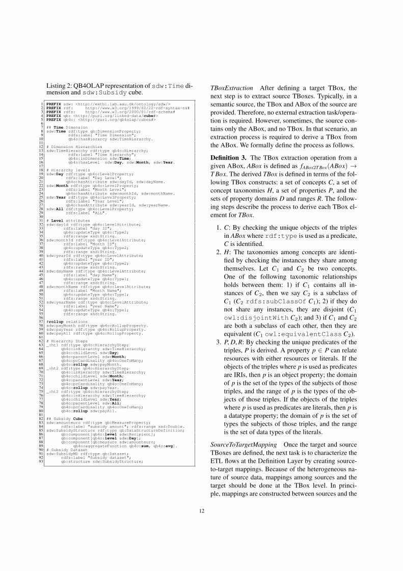
A mapping file is a Directed Acyclic Graph (DAG).Figure 7 shows the DAG representation of Listing 3.In this figure, the sources, intermediate results and theSDW are denoted as nodes of the DAG and edgesof the DAG represent the operations. The dotted-
15
:Subsidy_SubsidyMD
/map/subsidy.nt
/map/dbd.nt
/map/subsidy.nt
/map/sdw
Sources
SDW
/map/temp.nt (IR)
JoinTransformation
LevelMemberGenerator
Loader
/map/subsidy.nt
/map/temp1.nt (IR)
/map/temp2.nt (IR)
TransformationOnLiteral
ObservationGenerator
Loader
GraphExtractor
:Recipient_Company
:Recipient_RecipientMD
DAG
Fig. 7. The conceptual presentation of Listing 3.
lines shows the parts of the ETL covered by concept-mappings, represented by a rectangle.
6. The Execution Layer
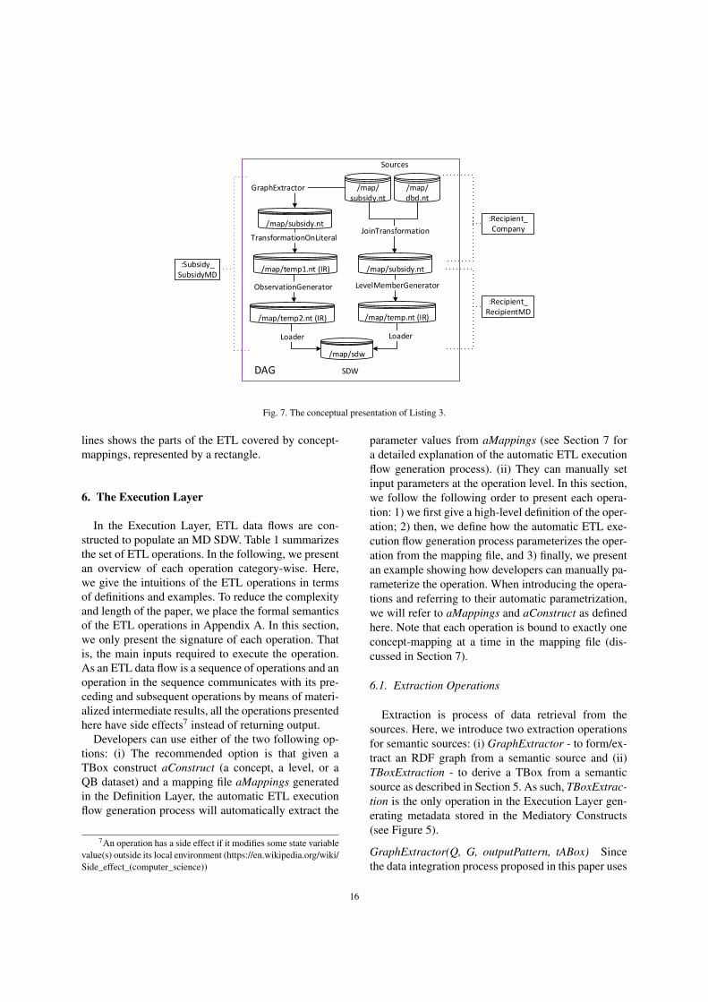
In the Execution Layer, ETL data flows are con-structed to populate an MD SDW. Table 1 summarizesthe set of ETL operations. In the following, we presentan overview of each operation category-wise. Here,we give the intuitions of the ETL operations in termsof definitions and examples. To reduce the complexityand length of the paper, we place the formal semanticsof the ETL operations in Appendix A. In this section,we only present the signature of each operation. Thatis, the main inputs required to execute the operation.As an ETL data flow is a sequence of operations and anoperation in the sequence communicates with its pre-ceding and subsequent operations by means of materi-alized intermediate results, all the operations presentedhere have side effects7 instead of returning output.
Developers can use either of the two following op-tions: (i) The recommended option is that given aTBox construct aConstruct (a concept, a level, or aQB dataset) and a mapping file aMappings generatedin the Definition Layer, the automatic ETL executionflow generation process will automatically extract the
7An operation has a side effect if it modifies some state variablevalue(s) outside its local environment (https://en.wikipedia.org/wiki/Side_effect_(computer_science))
parameter values from aMappings (see Section 7 fora detailed explanation of the automatic ETL executionflow generation process). (ii) They can manually setinput parameters at the operation level. In this section,we follow the following order to present each opera-tion: 1) we first give a high-level definition of the oper-ation; 2) then, we define how the automatic ETL exe-cution flow generation process parameterizes the oper-ation from the mapping file, and 3) finally, we presentan example showing how developers can manually pa-rameterize the operation. When introducing the opera-tions and referring to their automatic parametrization,we will refer to aMappings and aConstruct as definedhere. Note that each operation is bound to exactly oneconcept-mapping at a time in the mapping file (dis-cussed in Section 7).
6.1. Extraction Operations
Extraction is process of data retrieval from thesources. Here, we introduce two extraction operationsfor semantic sources: (i) GraphExtractor - to form/ex-tract an RDF graph from a semantic source and (ii)TBoxExtraction - to derive a TBox from a semanticsource as described in Section 5. As such, TBoxExtrac-tion is the only operation in the Execution Layer gen-erating metadata stored in the Mediatory Constructs(see Figure 5).
GraphExtractor(Q, G, outputPattern, tABox) Sincethe data integration process proposed in this paper uses
16
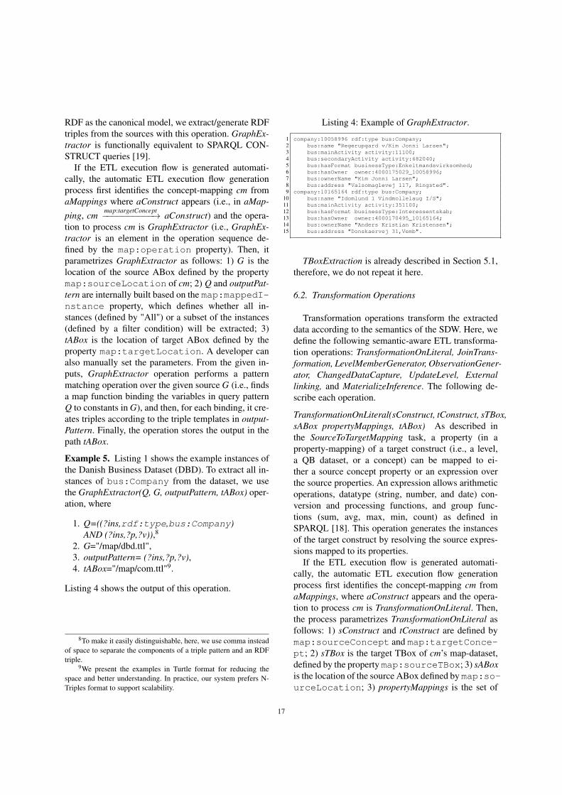
RDF as the canonical model, we extract/generate RDFtriples from the sources with this operation. GraphEx-tractor is functionally equivalent to SPARQL CON-STRUCT queries [19].
If the ETL execution flow is generated automati-cally, the automatic ETL execution flow generationprocess first identifies the concept-mapping cm fromaMappings where aConstruct appears (i.e., in aMap-
ping, cmmap:targetConcept−−−−−−−−−−→ aConstruct) and the opera-
tion to process cm is GraphExtractor (i.e., GraphEx-tractor is an element in the operation sequence de-fined by the map:operation property). Then, itparametrizes GraphExtractor as follows: 1) G is thelocation of the source ABox defined by the propertymap:sourceLocation of cm; 2) Q and outputPat-tern are internally built based on the map:mappedI-nstance property, which defines whether all in-stances (defined by "All") or a subset of the instances(defined by a filter condition) will be extracted; 3)tABox is the location of target ABox defined by theproperty map:targetLocation. A developer canalso manually set the parameters. From the given in-puts, GraphExtractor operation performs a patternmatching operation over the given source G (i.e., findsa map function binding the variables in query patternQ to constants in G), and then, for each binding, it cre-ates triples according to the triple templates in output-Pattern. Finally, the operation stores the output in thepath tABox.
Example 5. Listing 1 shows the example instances ofthe Danish Business Dataset (DBD). To extract all in-stances of bus:Company from the dataset, we usethe GraphExtractor(Q, G, outputPattern, tABox) oper-ation, where
1. Q=((?ins,rdf:type,bus:Company)AND (?ins,?p,?v)),8
2. G="/map/dbd.ttl",3. outputPattern= (?ins,?p,?v),4. tABox="/map/com.ttl"9.
Listing 4 shows the output of this operation.
8To make it easily distinguishable, here, we use comma insteadof space to separate the components of a triple pattern and an RDFtriple.
9We present the examples in Turtle format for reducing thespace and better understanding. In practice, our system prefers N-Triples format to support scalability.
Listing 4: Example of GraphExtractor.
1 company:10058996 rdf:type bus:Company;2 bus:name "Regerupgard v/Kim Jonni Larsen";3 bus:mainActivity activity:11100;4 bus:secondaryActivity activity:682040;5 bus:hasFormat businessType:Enkeltmandsvirksomhed;6 bus:hasOwner owner:4000175029_10058996;7 bus:ownerName "Kim Jonni Larsen";8 bus:address "Valsomaglevej 117, Ringsted".9 company:10165164 rdf:type bus:Company;
10 bus:name "Idomlund 1 Vindmollelaug I/S";11 bus:mainActivity activity:351100;12 bus:hasFormat businessType:Interessentskab;13 bus:hasOwner owner:4000170495_10165164;14 bus:ownerName "Anders Kristian Kristensen";15 bus:address "Donskaervej 31,Vemb".
TBoxExtraction is already described in Section 5.1,therefore, we do not repeat it here.
6.2. Transformation Operations
Transformation operations transform the extracteddata according to the semantics of the SDW. Here, wedefine the following semantic-aware ETL transforma-tion operations: TransformationOnLiteral, JoinTrans-formation, LevelMemberGenerator, ObservationGener-ator, ChangedDataCapture, UpdateLevel, Externallinking, and MaterializeInference. The following de-scribe each operation.
TransformationOnLiteral(sConstruct, tConstruct, sTBox,sABox propertyMappings, tABox) As described inthe SourceToTargetMapping task, a property (in aproperty-mapping) of a target construct (i.e., a level,a QB dataset, or a concept) can be mapped to ei-ther a source concept property or an expression overthe source properties. An expression allows arithmeticoperations, datatype (string, number, and date) con-version and processing functions, and group func-tions (sum, avg, max, min, count) as defined inSPARQL [18]. This operation generates the instancesof the target construct by resolving the source expres-sions mapped to its properties.
If the ETL execution flow is generated automati-cally, the automatic ETL execution flow generationprocess first identifies the concept-mapping cm fromaMappings, where aConstruct appears and the opera-tion to process cm is TransformationOnLiteral. Then,the process parametrizes TransformationOnLiteral asfollows: 1) sConstruct and tConstruct are defined bymap:sourceConcept and map:targetConce-pt; 2) sTBox is the target TBox of cm’s map-dataset,defined by the property map:sourceTBox; 3) sABoxis the location of the source ABox defined by map:so-urceLocation; 3) propertyMappings is the set of
17

property-mappings defined under cm; 4) tABox is thelocation of the target ABox defined by map:target-Location. A developer can also manually set theparameters. From the given inputs, this operationtransforms (or directly returns) the sABox triple ob-jects according to the expressions (defined throughmap:source4TargetPropertyValue) in prop-ertyMappings and stores the triples in tABox. Thisoperation first creates a SPARQL SELECT querybased on the expressions defined in propertyMappings,and then, on top of the SELECT query, it forms aSPARQL CONSTRUCT query to generate the trans-formed ABox for tConstruct.
Example 6. Listing 5 (lines 16-19) shows the trans-formed instances after applying the operation Trans-formationOnLiteral(sConstruct, tConstruct, sTBox,sABox, PropertyMappings, tABox), where
1. sConstruct = tConstruct=sub:Subsidy,2. sTBox="/map/subsidyTBox.ttl",3. sABox= source instances of sub:Subsidy (lines
47-50 in Listing 1),4. propertyMappings = lines 2-14 in Listing 5,5. tABox="/map/temp1.ttl".
Listing 5: Example of TransformationOnLiteral.
1 ## Property-mappings input2 :hasPayDate_Day rdf:type map:PropertyMapping;3 map:targetProperty sub:hasPayDate;4 map:sourceType4TargetPropertyValue map:Expression;5 map:source4TargetPropertyValue "CONCAT(STR(DAY(hasPayDate)),6 "/", STR(MONTH(hasPayDate)),"/",STR(YEAR(hasPayDate)))".7 :Recipient_recipientId rdf:type map:PropertyMapping;8 map:targetProperty sub:hasRecipient;9 map:sourceType4TargetPropertyValue map:Property;
10 map:source4TargetPropertyValue sub:hasRecipient.11 :amountEuro_amountEuro rdf:type map:PropertyMapping;12 map:targetProperty sub:amountEuro;13 map:sourceType4TargetPropertyValue map:Expression;14 map:source4TargetPropertyValue "xsd:integer(sub:amountEuro)".15 ## sub:Subsidy instances after TransformationOnLiteral.16 subsidy:10615413 rdf:type sub:Subsidy;17 sub:hasRecipient recipient:291894;18 sub:amountEuro 8928;19 sub:hasPayData "25/25/2010".
JoinTransformation(sConstruct, tConstruct, sTBox,tTBox, sABox, tABox, comProperty, propertyMap-pings) A TBox construct (a concept, a level, or aQB dataset) can be populated from multiple sources.Therefore, an operation is necessary to join and trans-form data coming from different sources. Two con-structs of the same or different sources can only bejoined if they share some common properties. This op-eration joins a source and a target constructs based ontheir common properties and produce the instances of
the target construct by resolving the source expressionsmapped to target properties. To join n sources, an ETLprocess requires n-1 JoinTransformation operations.
If the ETL execution flow is generated automati-cally, the automatic ETL execution flow generationprocess first identifies the concept-mapping cm fromaMappings, where aConstruct appears and the opera-tion to process cm is JoinTransformation. Then it pa-rameterizes JoinTransformation as follows: 1) sCon-struct and tConstruct are defined by the map:sourc-eConcept and map:targetConcept properties;2) sTBox and tTBox are the source and target TBox ofcm’s map-dataset, defined by map:sourceTBox andmap:targetTBox; 3) sABox and tABox are definedby the map:sourceLocation and map:target-Location properties; 4) comProperty is defined bymap:commonProperty; 5) propertyMappings isthe set of property-mappings defined under cm.
A developer can also manually set the parame-ters. Once it is parameterized, JoinTransformationjoins two constructs based on comProperty, transformstheir data based on the expressions (specified throughmap:source4TargetPropertyValue) definedin propertyMappings, and updates tABox based on thejoin result. It creates a SPARQL SELECT query join-ing two constructs using either AND or OPT features,and on top of that query, it forms a SPARQL CON-STRUCT query to generate the transformed tABox.
Example 7. The recipients in sdw:Recipientneed to be enriched with their company informationavailable in the Danish Business dataset. Therefore, ajoin operation is necessary between sub:Recipientand bus:Company. The concept-mapping of thisjoin is described in Listing 3 at lines 19-37. They arejoined by two concept properties: recipient names andtheir addresses (lines 31, 34-37). We join and trans-form bus:Company and sub:Recipient usingJoinTransformation(sConstruct, tConstruct, sTBox,tTBox, sABox, tABox, comProperty, propertyMap-pings), where
1. sConstruct= bus:Company,2. tConstruct= sub:Recipient,3. sTBox= "/map/businessTBox.ttl",4. tTBox= "/map/subsidyTBox.ttl",5. sABox= source instances of bus:Company (lines
13-29 in Listing 1),6. tABox= source instances of sub:Recipient
(lines 40-45 in Listing 1),7. comProperty = lines 31, 34-37 in Listing 3,8. propertyMappings = lines 73-96 in Listing 3.
18

Listing 6 shows the output of the joinTransformationoperation.
Listing 6: Example of JoinTransformation.
1 ## Example of sub:Recipient instances.2 recipient:291894 rdf:type sub:Recipient;3 sub:name "Kristian Kristensen";4 sub:cityId "Vemb";5 sub:companyId company:10165164;6 sub:businessType businessType:Interessentskab.
LevelMemberGenerator(sConstruct, level, sTBox, sABox,tTBox, iriValue, iriGraph, propertyMappings, tABox)In QB4OLAP, dimensional data are physically storedin levels. A level member, in an SDW, is describedby a unique IRI and its semantically linked properties(i.e., level attributes and rollup properties). This opera-tion generates data for a dimension schema defined inDefinition 1.
If the ETL execution flow is generated automati-cally, the automatic process first identifies the concept-mapping cm from aMappings, where aConstruct ap-pears and the operation to process cm is LevelMember-Generator. Then it parameterizes LevelMemberGener-ator as follows: 1) sConstruct is the source constructdefined by map:sourceConcept; 2) level is thetarget level10 defined by the map:targetConceptproperty; 3) sTBox and tTBox are the source and tar-get TBoxes of cm’s map dataset, defined by the prop-erties map:sourceTBox and map:targetTBox;4) sABox is the source ABox defined by the propertymap:sourceLocation; 5) iriValue is a rule11 tocreate IRIs for the level members and it is defineddefined by the map:TargetInstanceIriValueproperty; 6) iriGraph is the IRI graph12 within whichto look up IRIs, given by the developer in the auto-matic ETL flow generation process; 7) propertyMap-pings is the set of property-mappings defined undercm; 8) tABox is the target ABox location defined bymap:targetLocation.
A developer can also manually set the paramenters.Once it is parameterized, LevelMemberGenerator op-eration generates QB4OLAP-compliant triples for thelevel members of level based on the semantics encodedin tTBox and stores them in tABox.
10A level is termed as a level property in QB4OLAP, therefore,throughout this paper, we use both the term “level" and “level prop-erty" interchangeably.
11A rule can be either a source property, an expression or incre-mental, as described in Section 5.1.
12The IRI graph is an RDF graph that keeps a triple for eachresource in the SDW with their corresponding source IRI.
Example 8. Listing 3 shows a concept-mapping (lines40-54) describing how to populate sdw:Recipientfrom sub:Recipient. Listing 7 shows the levelmember created by the LevelMemberGenerator(level,tTBox, sABox, iriValue, iriGraph, propertyMappings,tABox) operation, where
1. sConstruct= sub:Recipient,2. level= sdw:Recipient,3. sTBox= "/map/subsidyTBox.ttl",4. sABox= "/map/subsidy.ttl", shown in Example 7,5. tTBox = "/map/subsidyMDTBox.ttl",6. iriValue = sub:recipientID,7. iriGraph = "/map/provGraph.nt",8. propertyMappings= lines 98-115 in Listing 3,9. tABox="/map/temp.ttl".
Listing 7: Example of LevelMemberGenerator.
1 PREFIX sdw: <http://extbi.lab.aau.dk/ontology/sdw/>2 PREFIX recipient: <http://extbi.lab.aau.dk/ontology3 /sdw/Recipient#>4 PREFIX company: <http://extbi.lab.aau.dk/ontology5 /sdw/Company#>6 PREFIX city: <http://extbi.lab.aau.dk/ontology7 /sdw/City#>8 ## Example of a recipient level member.9 recipient:291894 rdf:type qb4o:LevelMember;
10 qb4o:memberOf sdw:Recipient.11 sdw:name "Kristian Kristensen";12 sdw:inCity city:Vemb;13 sdw:hasCompany company:10165164.
ObservationGenerator(sConstruct, dataset, sTBox, sABox,tTBox, iriValue, iriGraph, propertyMappings, tABox)In QB4OLAP, an observation represents a fact. A factis uniquely identified by an IRI, which is defined bya combination of several members from different lev-els and contains values for different measure proper-ties. This operation generates data for a cube schemadefined in Definition 2.
If the ETL execution flow is generated automati-cally, the way used by the automatic ETL executionflow generation process to extract values for the pa-rameters of ObservationGenerator from aMappings isanalogous to LevelMemberGenerator. Developers canalso manually set the parameters. Once it is parame-terized, the operation generates QB4OLAP-complianttriples for observations of the QB datasetdataset basedon the semantics encoded in tTBox and stores them intABox.
Example 9. Listing 8 (lines 21-25) shows a QB4OL-AP-compliant observation create by the Observation-Generator(sConstruct, dataset, sTBox, sABox, tTBox,iriValue, iriGraph, propertyMappings, tABox) opera-tion, where
19

1. sConstruct=sub:Subsidy,2. dataset= sdw:SubsidyMD,3. sTBox="/map/subsidyTBox.ttl"4. sABox= "/map/subsidy.ttl", shown in Example 6,5. tTBox = "/map/subsidyMDTBox.ttl", shown in
Listing 2,6. iriValue = "Incremental",7. iriGraph = "/map/provGraph.nt",8. propertyMappings= lines 8-19 in Listing 8,9. tABox= "/map/temp2.ttl".
Listing 8: Example of ObservationGenerator.
1 PREFIX sdw: <http://extbi.lab.aau.dk/ontology/sdw/>2 PREFIX subsidy: <http://extbi.lab.aau.dk/ontology3 /sdw/Subsidy#>4 PREFIX recipient: <http://extbi.lab.aau.dk/ontology5 /sdw/Recipient#>6 PREFIX day: <http://extbi.lab.aau.dk/ontology/sdw/Day#>7 ## Property-Mappings8 :recipientId_Recipient rdf:type map:PropertyMapping;9 map:targetProperty sdw:Recipient;
10 map:sourceType4TargetPropertyValue map:Property;11 map:source4TargetPropertyValue sub:hasRecipient.12 :hasPayDate_Day rdf:type map:PropertyMapping;13 map:targetProperty sdw:Day;14 map:sourceType4TargetPropertyValue map:Property;15 map:source4TargetPropertyValue sub:hasPaydate.16 :amountEuro_amountEuro rdf:type map:PropertyMapping;17 map:targetProperty sdw:amountEuro;18 map:sourceType4TargetPropertyValue map:Property;19 map:source4TargetPropertyValue sub:amountEuro.20 ## Example of observations21 subsidy:_01 rdf:type qb4o:Observation;22 inDataset sdw:SubsidyMD;23 sdw:hasRecipient recipient:291894;24 sdw:amountEuro "8928.00";25 sdw:hasPayData day:25/25/2010.
ChangedDataCapture(nABox, oABox, flag) In a real-world scenario changes occur in a semantic sourceboth at the schema and instance level. Therefore,an SDW needs to take action based on the changedschema and instances. The adaption of the SDW TBoxwith the changes of source schemas is an analyticaltask and requires the involvement of domain experts,therefore, it is out of the scope of this paper. Here, onlythe changes at the instance level are considered.
If the ETL execution flow is generated automati-cally, the automatic process first identifies the concept-mapping cm from aMappings, where aConstruct ap-pears and the operation to process cm is ChangedDat-aCapture. Then, it takes map:sourceLocationand map:targetLocation for nABox (new di-mensional instances in a source) and oABox (old di-mensional instances in a source), respectively, to pa-rameterize this operations. flag depends on the next op-eration in the operation sequence.
Developers can also manually set the parameters.From the given inputs, ChangedDataCapture outputs
either 1) a set of new instances (in the case of SDWevolution, i.e., flag=0) or 2) a set of updated triples —the existing triples changed over time— (in the case ofSDW update, i.e., flag=1) and overwrites oABox. Thisis done by means of the set difference operation. Thisoperation must then be connected to either LevelMem-berGenerator to create the new level members or up-dateLevel (described below) to reflect the changes inthe existing level members.
Example 10. Suppose Listing 6 is the old ABox ofsub:Recipient and the new ABox is at lines 2-10in Listing 9. This operation outputs either 1) the newinstance set (in this case, lines 12-15 in the listing) or2) the updated triples (in this case, line 17).
Listing 9: Example of ChangedDataCapture.
1 ## New snapshot of sub:Recipient instances.2 recipient:291894 rdf:type sub:Recipient;3 sub:name "Kristian Jensen";4 sub:cityId "Vemb";5 sub:companyId company:10165164;6 businessType:Interessentskab.7 recipient:301894 rdf:type sub:Recipient;8 sub:name "Jack";9 sub:cityId "Aalborg";
10 sub:companyId company:100000.11 ## New instances to be inserted12 recipient:301894 rdf:type sub:Recipient;13 sub:name "Jack";14 sub:cityId "Aalborg";15 sub:companyId company:100000.16 ## Update triples17 recipient:291894 sub:name "Kristian Jensen".
UpdateLevel(level, updatedTriples, sABox tTBox, tABox,propertyMappings, iriGraph) Based on the triplesupdated in the source ABox sABox for the level level(generated by ChangedDataCapture), this operationupdates the target ABox tABox to reflect the changesin the SDW according to the semantics encoded in thetarget TBox tTBox and level property-mappings prop-ertyMappings. Here, we address three update types(Type1-update, Type2-update, and Type3-update), de-fined by Ralph Kimball in [14] for a traditional DW,in an SDW environment. The update types are definedin tTBox for each level attribute of level (as discussedin Section 2.3). As we consider only instance level up-dates, only the objects of the source updated triplesare updated. To reflect a source updated triple in level,the level member using the triple to describe itself,will be updated. In short, the level member is updatedin the following three ways: 1) A Type1-update sim-ply overwrites the old object with the current object.2) A Type2-update creates a new version for the levelmember (i.e., it keeps the previous version and createsa new updated one). It adds the validity interval for
20

both versions. Further, if the level member is a mem-ber of an upper level in the hierarchy of a dimension,the changes are propagated downward in the hierarchy,too. 3) A Type3-update overwrites the old object withthe new one. Besides, it adds an additional triple foreach changed object to keep the old object. The sub-ject of the additional triple is the instance IRI, the ob-ject of the triple is the old object, and the predicate isconcat(oldPredicate, "oldValue").
If the ETL execution flow is generated automati-cally, this operation first identifies the concept-mappingcm from aMappings, where aConstruct appears andthe operation to process cm is UpdateLevel. Then itparameterizes LevelMemberGenerator as follows: 1)level is defined by the map:targetConcept; 2)sABox is old source data; 3) updatedTriples is thesource location defined by map:sourceLocation;4) tTBox is the target TBox of cm’s map-dataset, de-fined by the property map:targetTBox; 5) tABoxis defined by map:targetLocation; 6) proper-tyMappings is the set of property-mappings definedunder cm; 7) iriGraph is given by developer in the au-tomatic ETL flow generation process.
Example 11. Listing 10 describes how different typesof updates work by considering two members of thesdw:Recipient level (lines 2-11). As the name ofthe second member (lines 7-11) is changed to “KristianJensen" from “Kristian Kristensen", as found in List-ing 9. A Type1-update simply overwrites the existingname (line 20). A Type2-update creates a new version(lines 39-46). Both old and new versions contain valid-ity interval (lines 35-37) and (lines 44-46). A Type3-Update overwrites the old name (line 56) and adds anew triple to keep the old name (line 57).
Listing 10: Example of different types of updates.
1 ## sdw:Recipient Level2 recipient:762921 rdf:type qb4o:LevelMember;3 qb4o:member sdw:Recipient;4 sdw:name "R. Nielsen";5 sdw:cityId city:Lokken;6 sdw:hasCompany company:10165164.7 recipient:291894 rdf:type qb4o:LevelMember;8 qb4o:memberOf sdw:Recipient.9 sdw:name "Kristian Kristensen";
10 sdw:cityId city:Vemb;11 sdw:hasCompany company:10165164.12 ## After type1 update13 recipient:762921 rdf:type qb4o:LevelMember;14 qb4o:member sdw:Recipient;15 sdw:name "R. Nielsen";16 sdw:cityId city:Lokken;17 sdw:hasCompany company:10165164.18 recipient:291894 rdf:type qb4o:LevelMember;19 qb4o:memberOf sdw:Recipient.20 sdw:name "Kristian Jensen";21 sdw:cityId city:Vemb;22 sdw:hasCompany company:10165164.23 ##After type2 update
24 recipient:762921 rdf:type qb4o:LevelMember;25 qb4o:member sdw:Recipient;26 sdw:name "R. Nielsen";27 sdw:cityId city:Lokken;28 sdw:hasCompany company:10165164.2930 recipient:291894 rdf:type qb4o:LevelMember;31 qb4o:memberOf sdw:Recipient.32 sdw:name "Kristian Kristensen";33 sdw:cityId city:Vemb;34 sdw:hasCompany company:10165164.35 sdw:fromDate ‘‘0000-00-00";36 sdw:toDate ‘‘2017-09-25";37 sdw:status ‘‘Expired".3839 recipient:291894\_2017\_09\_26 rdf:type qb4o:LevelMember;40 qb4o:memberOf sdw:Recipient.41 sdw:name "Kristian Jensen";42 sdw:cityId city:Vemb;43 sdw:hasCompany company:10165164;44 sdw:fromDate ‘‘2017-09-26";45 sdw:toDate ‘‘9999-12-31";46 sdw:status ‘‘Current".47 ## After type3 update48 recipient:762921 rdf:type qb4o:LevelMember;49 qb4o:member sdw:Recipient;50 sdw:name "R. Nielsen";51 sdw:cityId city:Lokken;52 sdw:hasCompany company:10165164.5354 recipient:291894 rdf:type qb4o:LevelMember;55 qb4o:memberOf sdw:Recipient.56 sdw:name "Kristian Jensen";57 sdw:name_oldValue "Kristian Kristensen";58 sdw:cityId city:Vemb;59 sdw:hasCompany company:10165164.
Besides the transformation operations discussedabove, we define two additional transformation op-erations that cannot be run by the automatic ETLdataflows generation process.
ExternalLinking (sABox, externalSource) This oper-ation links the resources of sABox with the resourcesof an external source externalSource. externalSourcecan either be a SPARQL endpoint or an API. For eachresource inRes ∈ sABox, this operation extracts topk matching external resources either 1) submitting aquery to externalSource or 2) by sending a web ser-vice request embedding inRes through the API (e.g.,DBpedia lookup API). To find a potential link for eachexternal resource exRes, the Jaccard Similarity of thesemantic bags of inRes and exRes is computed. The se-mantic bag of a resource consists of triples describingthe resource [20–22]. The pair of the internal and ex-ternal resources is considered as a match if the JaccardSimilarity exceeds a certain threshold. A triple withthe owl:sameAs property is created to materializethe link in sABox for each pair of matched internal andexternal resources.
MaterializeInference(ABox, TBox) This operationinfers new information that has not been explicitlystated in an SDW. It analyzes the semantics encodedinto the SDW and enriches the SDW with the inferredtriples. A subset of the OWL 2 RL/RDF rules, which
21

encodes part of the RDF-Based Semantics of OWL2 [23], are considered here. The reasoning rules canbe applied over the TBox TBox and ABox ABox sep-arately, and then together. Finally, the resulting infer-ence is asserted in the form of triples, in the same spiritas how SPARQL deals with inference.
6.3. Load
Loader(tripleSet, tsPath) An SDW is represented inthe form of RDF triples and the triples are stored in atriple store (e.g., Jena TDB). Given a set of RDF triplestriplesSet and the path of a triple store tsPath, this op-eration loads triplesSet in the triple store.
If the ETL execution flow is generated automati-cally, this operation first identifies the concept-mappingcm from aMappings, where aConstruct appears andthe operation to process cm is Loader. Then, it takesvalues of map:sourceLocation and map:targ-etLocation for the parameters tripleSet and tsPath.
7. Automatic ETL Execution Flow Generation
We can characterize ETL flows at the DefinitionLayer by means of the source-to-target mapping file;therefore, the ETL data flows in the Execution Layercan be generated automatically. This way, we can guar-antee that the created ETL data flows are sound andrelieve the developer from creating the ETL data flowsmanually. Note that this is possible because the Medi-atory Constructs (see Figure 5) contain all the requiredmetadata to automate the process.
Algorithm 1 shows the steps required to create ETLdata flows to populate a target construct (a level, a con-cept, or a dataset). As inputs, the algorithm takes a tar-get construct x, the mapping file G, and the IRI graphGIRI , and it outputs a set of ETL data flows E. At first,it locates x in G (line 1) and gets the concept-mappingswhere nodetarget participates (line 2). As a (final) tar-get construct can be populated from multiple sources,it can be connected to multiple concept-mappings, andfor each concept-mapping, it creates an ETL data flowby calling the function13 CREATEAFLOW (lines 5-8). Algorithm 2 generates an ETL data flow for aconcept-mapping c and recursively does so if the cur-rent concept-mapping source element is connected to
13Here, functions used in the algorithms are characterized by apattern over G, shown at its side as comments in the correspondingalgorithm.
Algorithm 1: CREATEETLInput: TargetConstruct x, MappingFile G,
IRIGraph GIRI
Output: A set of ETL flows Ebegin
1 nodetarget ← FIND(x,G)2 ?cmaps ←FINDCONMAP((nodetarget,G)
/* In G :
nodetargetmap:targetConcept←−−−−−−−−−−−−−?cmaps ;
|?cmaps| > 0 */3 E ← CREATESET()4 if (?cmaps 6= ∅) then5 foreach c ∈?cmaps do6 sc ← CREATESTACK()7 sc ← CREATEAFLOW(c, sc,G,GIRI)8 E.ADD(sc)
9 return E
Algorithm 2: CREATEAFLOW
Input: ConceptMapping c, Stack sc, MappingFileG, IRIGraph GIRI
Output: Stack sc
begin1 ops← FINDOPERATIONS(c,G)
/* In G : c map:operation−−−−−−−−−−→ ops */2 sc. PUSH(PARAMETERIZE(ops, c,G,GIRI))
/* Push parameterizedoperations in sc */
3 scon← FINDSOURCECONCEPT(c,G)
/* In G : c map:sourceConcept−−−−−−−−−−−−−→ scon */4 ?sconmap ← FINDCONMAP(scon,G)
/* In G :
scon map:targetConcept←−−−−−−−−−−−−−?sconmap;|?sconmap| 6 1 */
5 if (|?sconmap| = 1) then6 CREATEAFLOW(nc ∈?sconmap, sc,G)
/* recursive call with nc */
7 sc.PUSH(StartOp)/* Push the ETL start operation
to sc */8 return sc
another concept-mapping as, until it reaches a sourceelement. Algorithm 2 recursively calls itself and uses
22

Algorithm 3: PARAMETERIZE
Input: Seq ops, ConceptMapping cm,MappingFile G, IRIGraph GIRI
Output: Stack, sop
begin1 sop ← CREATESTACK()2 for (i = 1 to LENGTH(ops)) do3 if (i = 1) then4 PARAMETERIZEOP(op[i],G,
LOC(cm), GIRI)5 sop.PUSH(op[i])
6 PARAMETERIZEOP(op[i],G,OUTPUTPATH(op[i− 1]), GIRI)
7 sop.PUSH(op[i])
8 return sop
a stack to preserve the order of the partial ETL dataflows created for each concept-mapping. Eventually,the stack contains the whole ETL data flow betweenthe source and target schema.
Algorithm 2 works as follows. The sequence of op-erations in c is pushed to the stack after parameteriz-ing it (lines 1-2). Algorithm 3 parameterizes each op-eration in the sequence, as described in Section 6 andreturns a stack of parameterized operations. As inputs,it takes the operation sequence, the concept-mapping,the mapping file, and the IRI graph. For each opera-tion, it uses the PARAMETERIZEOP(op, G, LOC(cm),GIRI) function to automatically parameterize op fromG (as all required parameters are available in G) andpush the parameterized operation in a stack (line 2-7).Note that, for the first operation in the sequence, the al-gorithm uses the source ABox location of the concept-mapping (line 4) as an input, whereas for the remain-ing operations, it uses the output of the previous op-eration as input ABox (line 6). Finally, Algorithm 3returns the stack of parameterized operations.
Then, Algorithm 2 traverses to the adjacent concept-mapping of c connected via c’s source concept (line 3-4). After that, the algorithm recursively calls itself forthe adjacent concept-mapping (line 6). Note that, here,we set a restriction: except for the final target con-structs, all the intermediate source and target conceptscan be connected to at most one concept-mapping.This constraint is guaranteed when building the meta-data in the Definition Layer. Once there are no more in-termediate concept-mappings, the algorithm pushes adummy starting ETL operation (StartOp) (line 7) to the
stack and returns it. StartOp can be considered as theroot of the ETL data flows that starts the execution pro-cess. The stacks generated for each concept-mappingof nodetarget are added to the output set E (line 8 in Al-gorithm 1). The following section shows this processwith an example of our use case.
7.1. Auto ETL Example
In this section, we show how to populate sdw:Rec-ipient level using CREATEETL (Algorithm 1).As input, CREATEETL takes the target constructsdw:Recipient, the mapping file Listing 3 andthe location of IRI graph “/map/provGraph.nt". Fig-ure 8 presents a part (necessary to explain this pro-cess) of Listing 3 as an RDF graph. As soon assdw:Recipient is found in the graph, the next taskis to find the concept-mappings that are connected tosdw:Recipient through map:targetConcept(line 2). Here, ?cmaps={:Recipient_Recipien-tMD}. For :Recipient_RecipientMD, the al-gorithm creates an empty stack sc and calls CRE-ATEAFLOW (:Recipient_RecipientMD, sc, List-ing 3) (Algorithm 2) at lines 6-7.
CREATEAFLOW retrieves the sequence of opera-tions (line 1) needed to process the concept-mapping,here: ops=(LevelMemberGenerator; Loader) (see Fig-ure 8). Then, CREATEAFLOW parameterizes opsby calling PARAMETERIZE (Algorithm 3) and thenpushes the parameterized operations to sc (line 2).PARAMETERIZE creates an empty stack sop (line 1)and for each operation in ops it calls the PARAME-TERIZE() method to parameterize the operation usingthe concept-mapping information from Listing 3, thesource location of the concept-mapping, and the IRIgraph, and then it pushes the parameterized operationin sop (lines 2-7). After the execution of the for loop inPARAMETERIZE (line 2-7), the value of the stack sop is(Loader("/map/temp.nt", "/map/sdw"); LevelMember-Generator(sub:Recipient,sdw:Recipient,"/map/subsidyTBox.ttl", "/map/subsidy.nt", "/map/-subsidyMDTBox.ttl", sub:recipientID, "/map/-provGraph.nt", propertyMappings14, "/map/temp.nt")),which is returned to line 2 of CREATEAFLOW. Notethat the output path of LevelMemberGenerator(..)15
is used as the input source location of Loader(..).CREATEAFLOW pushes the parameterized operations
14Here, lines 95-112 in Listing 3.15(..) indicates that the operation is parameterized.
23

sdw:Recipient
:Recipient_RecipientMD
sub:Recipient
:Recipient_Company
bus:company
map:targetConcept
map:sourceConcept
map:targetConceptmap:sourceConcept
_:opSeq1
map:LevelMemberGenerator
map:Loader
map:operation
rdf:_1 rdf:_2
_:opSeq
map:operation
map:JoinTransformation
rdf:_1
“/map/dbd.nt” “/map/subsidy.nt” “/map/subsidy.nt” “/map/sdw.nt”
map:sourceLocation map:targetLocation map:targetLocationmap:sourceLocation
Fig. 8. The graph presentation of a part of Listing 3.
to sc (line 2), hence sc= (LevelMemberGenerator(..);
Loader(..)).
Then, CREATEAFLOW finds the source concept
of :Recipient_RecipientMD (line 3), which
is sub:Recipient; retrieves the concept-mapping
:Recipient_Company of sub:Recipient from
Listing 3 (line 4); and recursively calls itself for
:Recipient_Company (lines 5-6). The operation
sequence of :Recipient_Company (line 1) is
(JoinTransformation) (see Figure 8), and the call of
PARAMETERIZE at line 2 returns the parameterized
JoinTransformation(bus:Company, Sub:Reicip-
ient, "/map/dbd.nt","/map/subsidy.nt", comProperty16,
propertyMappings17) operation, which is pushed to the
stack sc, i.e., sc= (JoinTransformation(...); LevelMem-
berGenerator(...); Loader(...)). The source concept
bus:Company is not connected to any other concept-
mapping through the map:targetConcept prop-
erty in the mapping file. Therefore, CREATEAFLOW
skips lines 5 and 6. After that, it pushes the start op-
eration (StartOp) in sc, i.e., sc= (StartOp, JoinTrans-
formation(..); LevelMemberGenerator(..); Loader(..))
and returns it to CREATEETL (Algorithm 1) at line
7. Then, CREATEETL adds it to the set of ETL data
flows E and returns it (line 9). Therefore, the ETL
data flow to populate sdw:Recipient is StartOp
⇒JoinTransformation(..)⇒LevelMemberGenerator(..)
⇒Loader(..).
8. Evaluation
We created a GUI-based prototype, named SETLCON-
STRUCT [2] based on the different high-level constructsdescribed in Sections 5 and 6. We use Jena 3.4.0 toprocess, store, and query RDF data and Jena TDB as atriplestore. SETLCONSTRUCT is developed in Java 8. Likeother traditional tools (e.g., PDI [24]), SETLCONSTRUCT
allows developers to create ETL flows by dragging,dropping, and connecting the ETL operations. The sys-tem is demonstrated in [2]. On top of SETLCONSTRUCT,we implement the automatic ETL execution flow gen-eration process discussed in Section 7; we call itSETLAUTO. The source code, examples, and developermanual for SETLCONSTRUCT and SETLAUTO are avail-able at https://github.com/bi-setl/SETL.
To evaluate SETLCONSTRUCT and SETLAUTO, we cre-ate an MD SDW by integrating the Danish Busi-ness Dataset (DBD) [25] and the Subsidy dataset( https://data.farmsubsidy.org/Old/), described in Sec-tion 3. We choose this use case and these datasetsfor evaluation as there already exists an MD SDW,based on these datasets, that has been programaticallycreated using SETLPROG[10]. Our evaluation focuseson three aspects: 1) productivity, i.e., to what extentSETLCONSTRUCT and SETLAUTO ease the work of a de-veloper when developing an ETL task to process se-mantic data, 2) development time, the time to developan ETL process, and 3) performance, the time requiredto run the process. We run the experiments on a laptopwith a 2.10 GHz Intel Core(TM) i7-4600U processor,8 GB RAM, and Windows 10.
16lines 32,36-39 in Listing 3.17lines 76-93 in Listing 3.
24

Table 2Comparison among the productivity of SETLPROG, SETLCONSTRUCT, and SETLAUTO for the SDW.
Tool⇒
SETL
PRO
GSE
TLC
ON
STRU
CT
SETL
AUTO
NO
UC
Com
pone
ntso
fEac
hC
once
ptN
OU
CC
ompo
nent
sofE
ach
Con
cept
ET
LTa
sk⇓
Sub
Con
stru
ctPr
oced
ures
/D
ata
Stru
ctur
esN
UE
PN
OT
CTa
sk/O
pera
tion
Clic
ksSe
lect
ions
NO
TC
Clic
ksSe
lect
ions
NO
TC
TB
oxw
ithM
DSe
man
tics
Cub
eSt
ruct
ure
Con
cept
(),
Prop
erty
(),
Bla
nkN
ode(
),N
ames
pace
s(),
conc
eptP
rope
-rt
yBin
ding
s(),
crea
teO
ntol
ogy(
)
166
5
Targ
etT
Box
-D
efini
tion
19
97
19
97
Cub
eD
atas
et1
671
22
181
22
18D
imen
sion
224
52
34
122
34
12H
iera
rchy
730
37
46
187
46
18L
evel
1621
916
45
1716
45
17L
evel
Attr
ibut
e38
228
384
315
384
315
Rol
lup
Prop
erty
1283
122
17
122
17
Mea
sure
Prop
erty
182
14
325
14
325
Hie
rarc
hySt
ep12
315
126
66
126
66
Prefi
x21
7421
10
4821
10
48
Subt
otal
(for
the
Targ
etT
Box
)1
2450
910
138
234
219
0510
138
234
219
05
Map
ping
Gen
erat
ion
Map
ping
Dat
aset
N/A
00
Sour
ceTo
-Ta
rget
-M
appi
ng
51
26
31
26
Con
cept
-map
ping
dict
()17
243
239
100
1812
1015
Prop
erty
-map
ping
N/A
00
592
20
442
20
subt
otal
(for
the
Map
ping
File
)1
2052
8733
035
830
6525
327
447
3Se
man
ticD
ata
Ext
ract
ion
from
anR
DF
Dum
pFi
le-
quer
y()
1740
Gra
phE
xtra
ctor
175
030
1A
uto
Gen
erat
ion
Sem
antic
Dat
aE
xtra
ctio
nth
roug
ha
SPA
RQ
LE
ndpo
int
-E
xtra
ctTr
iple
s-Fr
omE
ndpo
int(
)0
100
Gra
phE
xtra
ctor
05
030
0A
uto
Gen
erat
ion
Cle
ansi
ng-
Bui
lt-in
Petl
func
tions
1580
Tran
sfor
mat
ion-
OnL
itera
l5
121
01
Aut
oG
ener
atio
n
Join
-B
uilt-
inPe
tlfu
nctio
ns1
112
Join
-Tr
ansf
orm
atio
n1
151
01
Aut
oG
ener
atio
n
Lev
elM
embe
rG
ener
atio
n-
crea
teD
ataT
ripl
eToF
ile()
,cr
eate
Dat
aTri
pleT
o-Tr
iple
Stor
e()
1675
Lev
elM
embe
r-G
ener
ator
166
60
1A
uto
Gen
erat
ion
Obs
erva
tion
Gen
erat
ion
-cr
eate
Dat
aTri
pleT
oFile
(),
crea
teD
ataT
ripl
eTo-
Trip
leSt
ore(
)1
75O
bser
vatio
n-G
ener
ator
16
60
1A
uto
Gen
erat
ion
Loa
ding
asR
DF
Dum
p-
inse
rtTr
iple
sInt
oTD
B()
,bu
lkL
oadT
oTD
B()
011
3L
oade
r0
12
00
Aut
oG
ener
atio
n
Loa
ding
toa
Trip
lest
ore
-in
sert
Trip
lesI
ntoT
DB
(),
bulk
Loa
dToT
DB
()17
153
Loa
der
171
20
1A
uto
Gen
erat
ion
Aut
oE
TL
Gen
erat
ion
--
--
Cre
ateE
TL
1-
--
121
160
Tota
l(fo
rth
eE
xecu
tion
Lay
erTa
sks)
128
0757
279
142
363
5821
160
Gra
ndTo
tal
(for
the
Who
leE
TL
Proc
ess)
129
358
245
991
826
2298
224
656
632
2378
25

8.1. Productivity
SETLPROG requires Python knowledge to maintainand implement an ETL process. On the other hand,using SETLCONSTRUCT and SETLAUTO, a developer cancreate all the phases of an ETL process by interact-ing with a GUI. Therefore, they provide a higher levelof abstraction to the developer that hides low-level de-tails and requires no programming background. Ta-ble 2 summarizes the effort required by the devel-oper to create different ETL tasks using SETLPROG,SETLCONSTRUCT, and SETLAUTO. We measure the de-veloper effort in terms of Number of Typed Charac-ters (NOTC) for SETLPROG and in Number of UsedConcepts (NOUC) for SETLCONSTRUCT and SETLAUTO.Here, we define a concept as a GUI component ofSETLCONSTRUCT that opens a new window to performa specific action. A concept is composed of severalclicks, selections, and typed characters. For each ETLtask, Table 2 lists: 1) its sub construct, required pro-cedures/data structures, number of the task used inthe ETL process (NUEP), and NOTC for SETLPROG;2) the required task/operation, NOUC, and number ofclicks, selections, and NOTC (for each concept) forSETLCONSTRUCT and SETLAUTO. Note that NOTC de-pends on the user input. Here, we generalize it by us-ing same user input for all systems. Therefore, the to-tal NOTC is not the summation of the values of therespective column.
To create a target TBox using SETLPROG, an ETLdeveloper needs to use the following steps: 1) defin-ing the TBox constructs by instantiating the Con-cept, Property, and BlankNode classes that play a metamodeling role for the constructs and 2) calling con-ceptPropertyBinding() and createTriples(). Both pro-cedures take the list of all concepts, properties, andblank nodes as parameters. The former one internallyconnects the constructs to each other, and the lattercreates triples for the TBox. To create the TBox ofour SDW using SETLPROG, we used 24,509 NOTC.On the other hand, SETLCONSTRUCT and SETLAUTO usethe TargetTBoxDefinition interface to create/edit a tar-get TBox. To create the target TBox of our SDWin SETLCONSTRUCT and SETLAUTO, we use 101 con-cepts that require only 382 clicks, 342 selections, and1905 NOTC. Therefore, for creating a target TBox,SETLCONSTRUCT and SETLAUTO reduce use 92% fewerNOTC than SETLPROG.
To create source-to-target mappings, SETLPROG usesPython dictionaries where the keys of each dictio-nary represent source constructs and values are the
mapped target TBox constructs, and for creating theETL process it uses 23 dictionaries, where the biggestdictionary used in the ETL process takes 253 NOTC.In total, SETLPROG uses 2052 NOTC for creatingmappings for the whole ETL process. On the con-trary, SETLCONSTRUCT and SETLAUTO use a GUI. Intotal, SETLCONSTRUCT uses 87 concepts composedof 330 clicks, 358 selections, and 30 NOTC. SinceSETLAUTO internally creates the intermediate map-pings, there is no need to create separate mappingdatasets and concept-mappings for intermediate re-sults. Thus, SETLAUTO uses only 65 concepts requir-ing 253 clicks, 274 selections, and 473 NOTC. There-fore, SETLCONSTRUCT reduces NOTC of SETLPROG
by 98%. Although SETLAUTO uses 22 less conceptsthan SETLCONSTRUCT, SETLCONSTRUCT reduces NOTCof SETLAUTO by 93%. This is because, in SETLAUTO,we write the data extraction queries in the concept-mappings where in SETLCONSTRUCT we set the data ex-traction queries in the ETL operation level.
To extract data from either an RDF local file or anSPARQL endpoint, SETLPROG uses the query() proce-dure and the ExtractTriplesFromEndpoint() class. Onthe other hand, SETLCONSTRUCT uses the GraphExtrac-tor operation. It uses 1 concept composed of 5 clicksand 20 NOTC for the local file and 1 concept with 5clicks and 30 NOTC for the endpoint. SETLPROG usesdifferent functions/procedures from the Petl Python li-brary (integrated with SETLPROG) based on the cleans-ing requirements. In SETLCONSTRUCT, all data cleansingrelated tasks on data sources are done using Transfor-mationOnLiteral (single source) and JoinTransforma-tion (for multi-source). TransformationOnLiteral re-quires 12 clicks and 1 selection, and JoinTransforma-tion takes 15 clicks and 1 selection.
To create a level member and observation, SETLPROG
uses createDataTripleToFile() and takes 125 NOTC.The procedure takes all the classes, properties, andblank nodes of a target TBox as input; therefore, thegiven TBox should be parsed for being used in theprocedure. On the other hand, SETLCONSTRUCT usesthe LevelMemberGenerator and ObservationGenera-tor operations, and each operation requires 1 concept,which takes 6 clicks and 6 selections. SETLPROG pro-vides procedures for either bulk or trickle loading toa file or an endpoint. Both procedures take 113 and153 NOTC, respectively. For loading RDF triples ei-ther to a file or a triple store, SETLCONSTRUCT uses theLoader operation, which needs 2 clicks and 2 selec-tions. Therefore, SETLCONSTRUCT reduces NOTC for alltransformation and loading tasks by 100%.
26

SETLAUTO requires only a target TBox and a map-ping file to generate ETL data flows through the Cre-ateETL interface, which takes only 1 concept com-posed of 21 clicks and 16 selections. Therefore, otherETL Layer tasks are automatically accomplished in-ternally. In summary, SETLCONSTRUCT uses 92% fewerNOTC than SETLPROG, and SETLAUTO further reducesNOUC by another 25%.
8.2. Development Time
We compare the time used by SETLPROG,SETLCONSTRUCT, and SETLAUTO to build the ETL pro-cesses for our use case SDW. As the three tools weredeveloped within the same project scope and we mas-ter them, the first author conducted this test. We chosethe running use case used in this paper and created asolution in each of the three tools and measured the de-velopment time. We used each tool twice to simulatethe improvement we may obtain when we are knowl-edgeable about a given project. The first time it takesmore time to analyze, think, and create the ETL pro-cess, and in the latter, we reduce the interaction timespent on analysis, typing, and clicking. Table 3 showsthe development time (in minutes) for main integrationtasks used by the different systems to create the ETLprocesses.
Table 3ETL development time (in minutes) required for SETLPROG,SETLCONSTRUCT, and SETLAUTO.
ToolIterationNumber
TargetTBoxDefinition
MappingGenerartion
ETLDesign
Total
SETLPROG 1 186 51 85 322SETLPROG 2 146 30 65 241
SETLCONSTRUCT 1 97 46 35 178SETLCONSTRUCT 2 58 36 30 124
SETLAUTO 1 97 40 2 139SETLAUTO 2 58 34 2 94
SETLPROG took twice as long as SETLCONSTRUCT andSETLAUTO to develop a target TBox. In SETLPROG, tocreate a target TBox construct, for example a levell, we need to instantiate the Concept() class for land then add its different property values by callingdifferent methods of Concept(). SETLCONSTRUCT andSETLAUTO create l by typing the input or selectingfrom the suggested items. Thus, SETLCONSTRUCT andSETLAUTO also reduce the risk of making mistakesin an error-prone task, such as creating an ETL. InSETLPROG, we typed all the source and target prop-
erties to create a mapping dictionary for each sourceand target concept pair. However, to create mappings,SETLCONSTRUCT and SETLAUTO select different con-structs from a source as well as a target TBox and onlyneed to type when there are expressions and/or filterconditions of queries. Moreover, SETLAUTO took lesstime than SETLCONSTRUCT in mapping generation be-cause we did not need to create mappings for interme-diate results.
To create ETL data flows using SETLPROG, wehad to write scripts for cleansing, extracting, trans-forming, and loading. SETLCONSTRUCT creates ETLflows using drag-and-drop options. Note that the map-pings in SETLCONSTRUCT and SETLAUTO use expres-sions to deal with cleansing and transforming relatedtasks; however, in SETLPROG we cleansed and trans-formed the data in the ETL design phase. Hence,SETLPROG took more time in designing ETL com-pared to SETLCONSTRUCT. On the other hand, SETLAUTO
creates the ETL data flows automatically from agiven mapping file and the target TBox. Therefore,SETLAUTO took only two minutes to create the flows.In short, SETLPROG is a programmatic environment,while SETLCONSTRUCT and SETLAUTO are drag anddrop tools. We exemplify this fact by means of Fig-ures 9 and 10, which showcase the creation of the ETLdata flows for the sdw:SubsidyMD dataset and thesdw:Recipient level. To make it more readableand understandable, we add comments at the end of thelines of Figure 9 and in each operation of Figure 10. Insummary, using SETLCONSTRUCT, the development timeis cut in almost half (41% less development time thanSETLPROG); and using SETLAUTO, it is cut by another27%.
Table 4ETL execution time required for each sub-phase of the ETL pro-cesses created using SETLPROG and SETLCONSTRUCT.
PerformanceMetrics
SystemsExtraction andTraditionalTransformation
SemanticTransformation
LoadingTotalProcessingTime
ProcessingTime (in minutes)
SETLPROG 33 17.86 21 71.86SETLCONSTRUCT 43.05 39.42 19 101.47
InputSize
SETLPROG6.2 GB (Jena TDB)+ 6.1 GB (N-Triples)
496 MB(CSV)
4.1 GB(N-Triples)
SETLCONSTRUCT6.2 GB (Jena TDB)+6.1 GB (N-Triples)
6.270 GB(N-Triples)
4.1 GB(N-Triples)
OutputSize
SETLPROG 490 MB (CSV)4.1 GB(N-Tripels)
3.7 GB(Jena TDB)
SETLCONSTRUCT6.270 GB(N-Triples)
4.1 GB(N-Triples)
3.7 GB(Jena TDB)
8.3. Performance
Since the ETL processes of SETLCONSTRUCT andSETLAUTO are the same and only differ in the de-
27

Fig. 9. The segment of the main method to populate the sdw:SubsidyMD dataset and the sdw:Recipient using SETLPROG.
Fig. 10. The ETL flows to populate the sdw:SubsidyMD dataset and the sdw:Recipient level using SETLCONSTRUCT.
veloper effort needed to create them, this sectiononly compares the performance of SETLPROG andSETLCONSTRUCT. We do so by analyzing the time re-quired to create the use case SDW by executing the re-spective ETL processes. To evaluate the performanceof similar types of operations, we divide an ETL pro-cess into three sub-phases: extraction and traditional
transformation, semantic transformation, as well asloading and discuss the time to complete each.
Table 4 shows the processing time (in minutes), in-put and output size of each sub-phase of the ETL pro-cesses created by SETLPROG and SETLCONSTRUCT. Theinput and output formats of each sub-phase are shownin parentheses. The extraction and traditional trans-
28
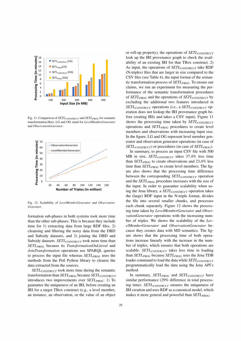
0
2
4
6
8
10
12
14
16
18
100 200 300 400 500Pro
cess
ing
Tim
e (
in m
inu
tes)
Input Size (in MB)
SETLCONSTRUCT(LG)
SETLPROG(LG)
SETLCONSTRICT(OG)
SETLPROG(OG)
SETLPROG(LG)
SETLCONSTRUCT (LG)
SETLCONSTRUCT (OG)
SETLPROG (OG)
Fig. 11. Comparison of SETLCONSTRUCT and SETLPROG for semantictransformation.Here, LG and OG stand for LevelMemberGeneratorand ObservationGenerator.
0
10
20
30
40
50
60
70
20 40 60 80 100 120 140 160Pro
cess
ing
Tim
e (
in m
inu
tes)
Number of Triples (in million)
ObservationGenerator
LevelMemberGenerator
Fig. 12. Scalability of LevelMemberGenerator and Observation-Generator.
formation sub-phases in both systems took more timethan the other sub-phases. This is because they includetime for 1) extracting data from large RDF files, 2)cleansing and filtering the noisy data from the DBDand Subsidy datasets, and 3) joining the DBD andSubsidy datasets. SETLCONSTRUCT took more time thanSETLPROG because its TransformationOnLiteral andJoinTransformation operations use SPARQL queriesto process the input file whereas SETLPROG uses themethods from the Petl Python library to cleanse thedata extracted from the sources.
SETLCONSTRUCT took more time during the semantictransformation than SETLPROG because SETLCONSTRUCT
introduces two improvements over SETLPROG: 1) Toguarantee the uniqueness of an IRI, before creating anIRI for a target TBox construct (e.g., a level member,an instance, an observation, or the value of an object
or roll-up property), the operations of SETLCONSTRUCT
look up the IRI provenance graph to check the avail-ability of an existing IRI for that TBox construct. 2)As input, the operations of SETLCONSTRUCT take RDF(N-triples) files that are larger in size compared to theCSV files (see Table 4), the input format of the seman-tic transformation process of SETLPROG. To ensure ourclaims, we run an experiment for measuring the per-formance of the semantic transformation proceduresof SETLPROG and the operations of SETLCONSTRUCT byexcluding the additional two features introduced inSETLCONSTRUCT operations (i.e., a SETLCONSTRUCT op-eration does not lookup the IRI provenance graph be-fore creating IRIs and takes a CSV input). Figure 11shows the processing time taken by SETLCONSTRUCT
operations and SETLPROG procedures to create levelmembers and observations with increasing input size.In the figure, LG and OG represent level member gen-erator and observation generator operations (in case ofSETLCONSTRUCT) or procedures (in case of SETLPROG).
In summary, to process an input CSV file with 500MB in size, SETLCONSTRUCT takes 37.4% less timethan SETLPROG to create observations and 23,4% lesstime than SETLPROG to create level members. The fig-ure also shows that the processing time differencebetween the corresponding SETLCONSTRUCT operationand the SETLPROG procedure increases with the size ofthe input. In order to guarantee scalability when us-ing the Jena library, a SETLCONSTRUCT operation takesthe (large) RDF input in the N-triple format, dividesthe file into several smaller chunks, and processeseach chunk separately. Figure 12 shows the process-ing time taken by LevelMemberGenerator and Obser-vationGenerator operations with the increasing num-ber of triples. We shows the scalability of the Lev-elMemberGenerator and ObservationGenerator be-cause they creates data with MD semantics. The fig-ure shows that the processing time of both opera-tions increase linearly with the increase in the num-ber of triples, which ensures that both operations arescalable. SETLCONSTRUCT takes less time in loadingthan SETLPROG because SETLPROG uses the Jena TDBloader command to load the data while SETLCONSTRUCT
programmatically load the data using the Jena API’smethod.
In summary, SETLPROG and SETLCONSTRUCT havesimilar performance (29% difference in total process-ing time). SETLCONSTRUCT ensures the uniqueness ofIRI creation and uses RDF as a canonical model, whichmakes it more general and powerful than SETLPROG.
29

Besides the differences of the performances alreadyexplained in Table 4, SETLCONSTRUCT also includes anoperation to update the members of the SDW levels,which is not included in SETLPROG. Since the ETL pro-cess for our use case SDW did not include that opera-tion, we scrutinize the performance of this specific op-eration of SETLCONSTRUCT in the following.
Performance analysis of UpdateLevel operation Fig-ure 13 shows the performance of the UpdateLevel op-eration. To evaluate this operation, we consider twolevels: mdProperty:Recipient and mdPrope-rty:City. We consider these two levels becausemdProperty:Recipient is the largest level (interms of size) in our use case, and mdProperty:Ci-ty is the immediate upper level of mdProperty:R-ecipient in the mdStructure:Address hierar-chy of the dimension mdProperty:Beneficiary.Therefore, we can record how the changes in citiespropagate to recipients, especially in Type2-update.The sdw:Recipient level is the lowest granular-ity level in the mdStructure:Address hierarchy;therefore, changes in a recipient (i.e., a member ofsdw:Recipient) only affect that recipient. Fig-ure 13a shows the processing time with the increas-ing number of recipients. As a Type2-update creates anew version for each changed level member, it takesmore time than a Type1-update and a Type3-update.A Type3-update takes more time than a Type1-updatebecause it keeps the record of old property values be-sides the current ones. Figure 13b shows how the sizeof the target ABox increases with the increasing num-ber of recipients. The target ABox size increases lin-early with the increasing number of recipients (see Fig-ure 13b) for Type2-update and Type-3 updates becausethey keep additional information. However, the targetABox size decreases with the increasing number of re-cipients for Type1-updates; this is because the currentproperty-values are smaller than the older ones in size.
Figure 13c shows the processing time when increas-ing the number of updated cities. Since sdw:Cityis the immediate upper level of sdw:Recipient inthe mdStructure:address hierarchy, to reflecta changed city in the target ABox, a Type2-updatecreates new versions for itself as well as for the re-cipients living in that city. Therefore, a Type2-updatetakes more processing time in comparison to a Type1-update and a Type-3 update. Figure 13d shows the tar-get ABox size with the increasing number of cities.The figure shows that the target ABox size for Type2-updates increases slowly within the range from 120 to
160 (X-axis), and it indicates that the changed citieswithin this range contain fewer recipients than thecities in other ranges.
In overall, we conclude that SETLPROG and SETLCON-
STRUCT have similar performance and SETLCONSTRUCT isa scalable framework. Moreover, SETLCONSTRUCT sup-ports SDWs update.
9. Related Work
Nowadays, combining SW and BI technologies isan emerging research topic as it opens interesting re-search opportunities. As a DW deals with both inter-nal and (increasingly) external data presented in het-erogeneous formats, especially in the RDF format, se-mantic issues should be considered in the integrationprocess [26]. Furthermore, the popularity of SW datagives rise to new requirements for BI tools to enableOLAP-style analysis over this type of data [27]. There-fore, the existing research related to semantic ETL isdivided into two lines: 1) on the one hand, the use ofSW technologies to physically integrate heterogeneoussources and 2) on the other hand, enabling OLAP anal-ysis over SW data.
One prominent example following the first researchline is [28], which presents an ontology-based ap-proach to enable the construction of ETL flows. Atfirst, the schema of both the sources and the DW aredefined by a common graph-based model, named thedatastore graph. Then, the semantics of the datastoregraphs of the data sources and the DW are describedby generating an (OWL-based) application ontology,and the mappings between the sources and the tar-get are established through that ontology. In this waythis approach addresses heterogeneity issues amongthe source and target schemata and finally demon-strates how the use of an ontology enables a high de-gree of automation from the source to the target at-tributes, along with the appropriate ETL transforma-tions. Nonetheless, computationally complex ETL op-erations like slowly changing dimensions and the an-notation of the application ontology with MD seman-tics are not addressed in this work. Therefore, OLAPqueries cannot be applied on the generated DW.
Another piece of existing work [29] aligned to thisline of research proposes a methodology describingsome important steps required to make an SDW, whichenables to integrate data from semantic databases. Thisapproach also misses the annotation of the SDW withMD semantics. [30] has proposed an approach to sup-
30

0
10
20
30
40
50
60
70
Tim
e (
in m
inu
tes)
Number of Changed Recipient Members (in thousand)
Type1-update
Type2-update
Type3-update
(a) Processing time of increasing changed recipient members.
250
350
450
550
650
750
50 100 150 200 250
Targ
et A
Bo
x Si
ze (
in M
B)
Number of Changed Recipient Members (in thousand)
Update Type1
Update Type2
Update Type3
(b) Target size of increasing changed recipient members.
0
5
10
15
20
25
40 80 120 160 220
Tim
e (
in m
inu
tes)
Number of Changed City Members (in thousand)
Type1-update
Type3-update
Type2-update
(c) Processing time of increasing changed city members.
280
330
380
430
480
530
40 80 120 160 220
Targ
et A
Bo
x Si
ze (
in M
B)
Number of Changed City Members (in thousand)
Type1-update
Type3-update
Type2-update
(d) Target size of increasing changed city members.
Fig. 13. Performance of UpdateLevel based on processing time and target ABox size with the changing of the sdw:Recipient and sdw:Citymembers.
port data integration tasks in two steps: 1) construct-ing ontologies from XML and relational sources and2) integrating the derived ontologies by means of exist-ing ontology alignment and merging techniques. How-ever, ontology alignment techniques are complex anderror-prone. [31] presents a semantic ETL frameworkat the conceptual level. This approach utilizes the SWtechnologies to facilitate the integration process anddiscusses the use of different available tools to per-form different steps of the ETL process. [25] presentsa method to spatially integrate a Danish Agriculturaldataset and a Danish Business dataset using an ontol-ogy. The approach uses SQL views and other man-ual processes to cleanse the data and Virtuoso for cre-ating and storing integrated RDF data. [32] presentsUnifiedViews, an open-source ETL framework thatsupports management of RDF data. Based on the
SPARQL queries, they define four types of Data Pro-cessing Units (DPUs): Extractor, Transformer, Loader,and Quality Assessor. However, the DPUs do not sup-port to generate MD RDF data.
In the second line of research, a prominent paper is[4], which outlines a semi-automatic method for incor-porating SW data into a traditional MD data manage-ment system for OLAP analysis. The proposed methodallows an analyst to accomplish the following tasks:1) designing the MD schema from the TBox of anRDF dataset, 2) extracting the facts from the ABox ofthe dataset and populating the MD fact table, and 3)producing the dimension hierarchies from instances ofthe fact table and the TBox to enable MDX queriesover the generated DW. However, the generated DWno longer preserves the SW data principles definedin [5]; thus, OLAP analysis directly over SW data is
31

yet to be addressed. To address this issue, [33] in-troduces the notion of a lens, called the analyticalschema, over an RDF dataset. An analytical schemais a graph of classes and properties, where each nodeof the schema presents a set of facts that can be ana-lyzed by traversing the reachable nodes. [34] presentsa self-service OLAP endpoint for an RDF dataset. Thisapproach first superimposes an MD schema over theRDF dataset. Then, a semantic analysis graph is gener-ated on top of that MD schema, where each node of thegraph represents an analysis situation corresponding toan MD query, and an edge indicates a set of OLAPoperations.
Both [33] and [34] require either a lens or a se-mantic analysis graph to define MD views over anRDF dataset. Since most published SW data containsfacts and figures, W3C recommends the Data Cube(QB) [13] vocabulary to standardize the publication ofSW data with MD semantics. Although QB is appro-priate to publish statistical data and several publishers(e.g., [35]) have already used the vocabulary for pub-lishing statistical datasets, it has limitations to defineMD semantics properly. The QB4OLAP [36] vocabu-lary enriches QB to support MD semantics by provid-ing constructs to define 1) a cube structure in terms ofdifferent level of dimensions, measures, and attachingaggregate functions with measures and 2) a dimensionstructure in terms of levels, level attributes, relation-ships, the cardinality of relationships among the levels,and hierarchies of the dimension. Therefore, MD datacan be published either by enriching data already pub-lished using QB with dimension levels, level members,dimension hierarchies, and the association of aggre-gate functions to measures without affecting the exist-ing observations [7] or using QB4OLAP from scratch[10, 37, 38].
In [39], the authors present an approach to enableOLAP operations on a single data cube publishedusing the QB vocabulary and shown the applicabil-ity of their OLAP-to-SPARQL mapping in answeringbusiness questions in the financial domain. However,their OLAP-to-SPARQL mapping may not result inthe most efficient SPARQL query and requires addi-tional efforts and a longer time to get the results as theyconsider that the cube is queried on demand and theDW is not materialized. While some approaches haveproposed techniques to optimize execution of OLAP-style SPARQL queries in a federated setting [40], oth-ers have considered view materialization [41, 42]. Theauthors in [7] present a semi-automatic method to en-rich the QB dataset with QB4OLAP terms. However,
there is no guideline for an ETL process to populate aDW annotated with QB4OLAP terms.
After analyzing the two research lines, we can drawsome conclusions. Although each approach describedabove addresses one or more aspects of a semanticETL framework, there is no single platform that sup-ports them all (target definition, source-to-target map-pings generation, ETL generations, MD target pop-ulation, and evolution). To solve this problem, wehave proposed a Python-based programmable seman-tic ETL (SETLPROG) framework [10] that provides anumber of powerful modules, classes, and methodsfor performing the tasks mentioned above. It facili-tates developers by providing a higher abstraction levelthat lowers the entry barriers. We have experimen-tally shown that SETLPROG performs better in termsof programmer productivity, knowledge base quality,and performance, compared to other existing solutions.However, to use it, developers need a programmingbackground. Although SETLPROG enables to create anETL flow and provides methods by combining severaltasks, there is a lack of a well-defined set of basic se-mantic ETL constructs that allow users more controlin creating their ETL process. Moreover, how to up-date an SDW to synchronize it with the changes tak-ing place in the sources is not discussed. Further, ina data lake/big data environment, the data may comefrom heterogeneous formats, and the use of the rela-tional model as the canonical model may generate anoverhead. Transforming JSON or XML data to rela-tional data to finally generate RDF can be avoided byusing RDF as the canonical model instead. To this end,several works have discussed the appropriateness ofknowledge graphs for data integration purposes andspecifically, as a canonical data model [43–45]. An ad-ditional benefit of using RDF as a canonical modelis that it allows adding semantics without being com-pliant to a fixed schema. The present paper presentsthe improvements introduced on top of SETLPROG toremedy its main drawbacks discussed above. As thereare available RDF Wrappers (e.g., [46, 47]) to con-vert another format to RDF, in this paper, we focus ononly semantic data and propose an RDF-based two-layered (Definition Layer and Execution Layer) inte-gration process. We also propose a set of high-levelETL constructs (tasks/operations) for each layer, withthe aim of overcoming the drawbacks identified abovefor SETLPROG. We also provide an operation to updatean SDW based on the changes in source data. On topof that, we characterize the ETL flow in the DefinitionLayer by means of creating an RDF based source-to-
32

target mapping file, which allows to automate the ETLexecution flows.
10. Conclusion and Future Work
In this paper, we proposed a framework of a setof high-level ETL constructs to integrate semanticdata sources. The overall integration process uses theRDF model as canonical model and is divided intothe Definition and Execution Layer. In the Defini-tion Layer, ETL developers create the metadata (targetand source TBoxes, and source-to-target mappings).We propose a set of high-level ETL operations forsemantic data that can be used to create ETL dataflows in the Execution Layer. As we characterize thetransformations in the Definition Layer in terms ofsource-to-target mappings at the schema level, we areable to propose an automatic algorithm to generateETL data flows in the Execution Layer. We devel-oped an end-to-end prototype SETLCONSTRUCT based onthe high-level constructs proposed in this paper. Wealso extended it to enable automatic ETL executionflows generation (and named it SETLAUTO). The exper-iment shows that 1) SETLCONSTRUCT uses 92% fewerNOTC than SETLPROG, and SETLAUTO further reducesNOUC by another 25%; 2) usingSETLCONSTRUCT, thedevelopment time is almost cut in half compared toSETLPROG, and is cut by another 27% using SETLAUTO;3) SETLCONSTRUCT is scalable and has similar perfor-mance compared to SETLPROG.
An extension of this work is to define the formalsemantics of the operations using an ontology andmathematically prove the correctness and complete-ness of the proposed ETL constructs. The source-to-target mappings act as a mediator to generate data ac-cording to the semantics encoded in the target. There-fore, we plan to extend our framework from purelyphysical to also virtual data integration where insteadof materializing all source data in the DW, ETL pro-cesses will run on demand. When considering virtualdata integration, it is important to develop query opti-mization techniques for OLAP queries on virtual se-mantic DWs, similar to the ones developed for virtualintegration of data cubes and XML data [48–50]. An-other interesting work will be to apply this layer-basedintegration process in a Big Data and Data Lake en-vironment. The metadata produced in the DefinitionLayer can be used as basis to develop advanced catalogfeatures for Data Lakes. Furthermore, we plan to in-vestigate how to integrate provenance information into
the process [51]. Another aspect of future work is thesupport of spatial data [52, 53]. We will also develop anew implementation with scalable, parallel ETL com-puting and optimize the operations.
Acknowledgements
This research is partially funded by the EuropeanCommission through the Erasmus Mundus Joint Doc-torate Information Technologies for Business Intelli-gence (EM IT4BI-DC), the Poul Due Jensen Founda-tion, and the Danish Council for Independent Research(DFF) under grant agreement no. DFF-8048-00051B.
Appendix A
A.1. Semantics of the Execution Layer Operations
In this section, we provide the detailed semantics ofthe ETL operations described in Section 6. The oper-ations depend on some auxiliary functions. Here, wefirst present the semantics of the auxiliary functionsand then the semantics of the operations. We presenteach function and operation in terms of input Param-eters and semantics. To distinguish the auxiliary func-tions from the operations, we use small capital lettersto write an auxiliary function name, while an operationname is written in italics.
A.1.1. Auxiliary Functions
EXECUTEQUERY(Q, G, outputHeader) This func-tion provides similar functionality as SPARQL SE-LECT queries.
Input Parameters: Let I, B, L, and V be the setsof IRIs, blank nodes, literals, and query variables. Wedenote the set of RDF terms (I ∪ B ∪ L) as T for anRDF graph G. V is disjoint from T . A query variablev ∈ V is prefixed by the symbol ′?′. A query pattern Qcan be recursively defined as follows18:
1. An RDF triple pattern tp is a query pattern Q. Atp
19 allows query variables in any positions of anRDF triple, i.e., tp ∈ (I∪B∪V)×(I∪V)×(T∪V).
18We follow the same syntax and semantics used in [54] for aquery pattern.
19To make it easily distinguishable, here we use comma to sepa-rate the components of a triple pattern and an RDF triple.
33

2. If Q1 and Q2 are query patterns, then (Q1 ANDQ2), (Q1 OPT Q2), and (Q1 UNION Q2) arealso query patterns.
3. If Q is a query pattern and Fc is a filter condi-tion then (Q FILT ER Fc) is a query pattern. Afilter condition is constructed using elements ofthe set (T ∪V) and constants, the equality symbol(=), inequality symbols (<,>,6, >), logical con-nectivities (¬,∨,∧), unary predicates like bound,isBlank, and isIRI plus other features describedin [55].
G is an RDF graph over which Q is evaluated andoutputHeader is an output header list, which is a list ofquery variables and/or expressions over the variablesused in Q. Here, expressions are standard SPARQL ex-pressions defined in [18].
Semantics: For the query pattern Q, let µ be a partialfunction that maps var(Q) to T , i.e., µ : var(Q) → T .The domain of µ, denoted by dom(µ), is the set of vari-ables occurring in Q for which µ is defined. We abusenotation and say µ(Q) is the set of triples obtained byreplacing the variables in the triple patterns of Q ac-cording to µ. The semantics of the query pattern arerecursively described below.
1. If the query pattern Q is a triple pattern tp, thenthe evaluation of Q against G is the set of allmappings that can map tp to a triple containedin G, i.e., JQKG = JtpKG = {µ | dom(µ) =var(tp) ∧ µ(tp) ∈ G}.
2. If Q is (Q1 AND Q2), then JQKG is the naturaljoin of JQ1KG and JQ2KG, i.e., JQKG = JQ1KG ./JQ2KG = {µ1 ∪ µ2 | µ1 ∈ JQ1KG, µ2 ∈ JQ2KG,µ1 and µ2 are compatible mappings, i.e., ∀?x ∈dom(µ1) ∩ dom(µ2), µ1(?x) = µ2(?x)}.
3. If Q is (Q1 OPT Q2), then JQKG is the left outerjoin of JQ1KG and JQ2KG, i.e., JQKG = JQ1KG =./JQ2KG = (JQ1KG ./ JQ2KG) ∪ (JQ1KG \ (JQ2KG).
4. If Q is (Q1 UNION Q2), then JQKG = JQ1KG ∪JQ2KG = {µ | µ ∈ JQ1KG or µ ∈ JQ2KG }.
5. If Q = (Q1 FILT ER Fc), then JQKG = {µ | µ ∈JQ1KG ∧ µ |= Fc}, where a mapping µ satisfiesa filter condition Fc, denoted by µ |= Fc.
This function returns a set of tuples where each tu-ple contains the values of the variables and/or thevalues derived by solving the expressions defined inoutputHeader according to µ.
GETPROPERTIESFROMEXPRESSIONS(sTBox, exps) Anexpression is a combination of one or more proper-ties, operators, and SPARQL functions defined in [18].
This function returns a subset of properties of a sourceTBox that are used in the given expressions.
Input Parameters: sTBox is a TBox and exps is aset of expressions.
Semantics: For each exp ∈ exps, this functioncomputes the intersection of the set of IRIs used in expand the set of properties of sTBox. Then, it returns theunion of all intersection sets. Here, returnIRIs(exp) re-turns the set of IRIs used in exp and P(t) is defined inEquation 2. The semantic is defined as follows:
GETPROPERTIESFROMEXPRESSIONS(sT Box,
exps) =⋃
exp∈exps
returnIRIs(exp)∩P(sT Box).
This function returns a set of properties.
VALIDATEEXPRESSIONS(exps,Q, flag) The sourceexpressions/properties (defined by map:source4Ta-rgetPropertyValue) in property-mappings con-tains properties. However, the outputHeader parame-ter of EXECUTEQUERY() allows only query variables.Therefore to extract data from an RDF graph usingEXECUTEQUERY(), the properties used in the expres-sions/properties of property-mappings should be re-placed by corresponding query variables. On the otherhand, to match the expressions/properties used in out-putHeader of EXECUTEQUERY() with the expression-s/properties (defined by map:source4TargetPro-pertyValue) in property-mappings , the query vari-ables used in expressions/properties need to be re-placed by the corresponding properties. Given a set ofexpressions, a query pattern, and a flag, this functionreplaces the used term (either IRI or query variables) inexpressions with alternative ones from the query pat-tern based on the flag and returns a list of the validatedexpressions.
Input Parameters: exps is a list of expressions, Qis a query pattern, and flag indicates whether it willreplace the IRIs (flag=1) or query variables (flag=0)used in exps.
Semantics: If flag=1 the function replaces the expsIRIs with the corresponding query variables used inQ. For each IRI iri used in an expression, VALIDATE-EXPRESSIONS replaces iri with the object of the triplepattern whose predicate is iri in Q. Finally, it returnsthe list of expressions, where each expression does notcontain any IRIs.
If flag=0 the function replaces the exps query vari-ables with the corresponding predicate IRIs used in
34
Q. For each query variable ?q used in an expression,it replaces ?q with the predicate of the triple patternwhose object is ?q in Q. Finally, it returns the list ofexpressions, where each expression does not containany query variables.
MAPPEDSOURCEINSTANCES(sc, sTBox, sABox, prop-ertyMappings) This function returns a dictionary de-scribing the instances of a source concept.
Input Parameters: sc is a source construct, sT Boxand sABox are the source TBox and ABox, property−Mappings is a set of property-mappings.
Semantics: At first, this function retrieves instancesof sc with their corresponding properties and val-ues. Here, we consider only those properties that aredirectly mapped to target properties and/or used insource expressions. Both the properties and expres-sions are defined in propertyMappings by map:sour-ce4TargetPropertyValue. Then, it creates adictionary, a set of (key, value) pairs. In a pair, key rep-resents an instance IRI and value in turn represents aset of (pi, vi) pairs, where pi represents a property andvi represents a value for pi. It is explained as follows:
MAPPEDSOURCEINSTANCES(sc, sT Box, sABox,
propertyMapping) = dictionary(EXECUTEQU-
ERY((?i,rdf:type20, sc)AND(?i, ?p, ?v)FILT ER
(?p ∈ GETPROPERTIESFROMEXPRESSIONS(
sT Box,mappedExpressions(sc, propertyMap
pings)))), sABox, (?i, ?p, ?v))).
Here, mappedExpressions(sc, propertyMappings)returns the set of source properties/expressions (de-fined by map:source4TargetPropertyValue)used in propertyMappings. The dictionary((?i, ?p, ?v))function first groups the input tuples by ?i and thenfor each instance i ∈?i, it creates a set of (pi, vi) pairs,where pi is a property of i and vi is the value for pi.Finally, MAPPEDSOURCEINSTANCES(..) returns thedictionary created.
GENERATEIRI(sIRI, value, tType, tTBox, iriGraph ) Ev-ery resource in an SDW is uniquely identified by anIRI defined under the namespace of the SDW. Thisfunction creates an equivalent target IRI for a sourceresource. Additionally, it keeps that information in theIRI graph.
Input Parameters: sIRI is the source IRI, value isthe literal to be used to ensure the uniqueness of the
generated IRI, tType is the type of the generated IRI intT Box, tT Box is the target TBox, and iriGraph is theIRI graph. The IRI graph is an RDF graph that keepsa triple for each resource in the SDW with their corre-sponding source IRI.
Semantics: Equation 3 formulates how to cre-ate the IRI. First, the function checks whether thereis an equivalent IRI for sIRI in iriGraph usinglookup(sIRI, iriGraph). It returns the target IRI ifit finds an existing IRI in iriGraph; otherwise, itgenerates a new IRI by concatenating prefix(tTBox)and validate(value) for a target concept or property,or creates an instance IRI by concatenating tTypeand validate(value). Here, prefix(tTBox) returns thenamespace of tT Box; concat() concatenates the inputstrings; validate(value) modifies value according tothe naming convention rules of IRIs described in [56];C(T ) and P(T ) are defined in Equation 1 and 2. Uponthe creation of the IRI, this function adds an RDF triple(tIRI owl:sameAs sIRI) to iriGraph.
generateIRI(sIRI, value, tType, tTBox, iriGraph )=
lookup(sIRI, iriGraph) i f lookup(sIRI, iriGraph)! =NULL
concat(tType, “#”,
validate(value)) i f lookup(value, iriGraph) =NULL ∧ tType ∈ (C(tT Box)∪P(tT Box))
concat(pre f ix(tT Box),“#”, validate(value)) i f lookup(sIRI, iriGraph) =
NULL ∧ tType /∈ (C(tT Box)∪P(tT Box))
(3)
This function returns an IRI.
TUPLESTOTRIPLES(T, tc, Q, propertyMappings,(i, exp1, .., expn)) As the canonical model of our in-
tegration process is RDF model, we need to convertthe instance descriptions given in the tuple format intoequivalent RDF triples. This function returns a set ofRDF triples from the given set of tuples.
Input Parameters: T is a set of tuples (1st normalform tabular format), tc is a target construct, Q is aquery pattern, propertyMappings is a set of property-mappings, and (i, exp1, .., expn) is the tuple format.
Semantics: Equation 4 shows the semantics of thisfunction. Each tuple of T represents an instance-to-be of the target construct tc, and each expression(expi) and the value of the expression (val(expi))represent the corresponding target property and itsvalue of the instance. Here, val(expi) is the valueof an expression in a source tuple. As an expres-sion can contain query variables and expressionsused in propertyMappings do not use query vari-ables, VALIDATEEXPRESSIONS(expi, Q, 0) replaces
35

the query variables with equivalent properties fromQ, and return(x, propertyMappings) returns the tar-get construct mapped to source construct x frompropertyMappings.
TUPLESTOTRIPLES(T, tc,Q, propertyMappings,
(i, exp1, .., expn)) =⋃(val(i),val(exp1),..,val(expn))∈T
{{(val(i),rdf:type, tc
))} ∪n⋃
p=1
{(val(i), return(VALIDATEEXPRESSIONS
(expp,Q, 0), propertyMappings), val(expi))}}(4)
This function returns a set of RDF triples.
A.1.2. Execution Layer OperationsThis section gives the semantics of each operation
category-wise.Extraction Operations
GraphExtractor(Q, G, outputPattern, tABox) This op-eration is functionally equivalent to SPARQL CON-STRUCT queries to extract data from sources.
Input Parameters: Q is a query pattern as definedin EXECUTEQUERY(). G is an RDF graph over whichQ is evaluated. The parameter outputPattern is a setof triple patterns from (I ∪ B ∪ var(Q)) × (I ∪var(Q)×(T ∪var(Q)), where var(Q) ⊆ V is the set ofquery variables occurring in Q. Here, I, B,T, and V arethe sets defined in EXECUTEQUERY(). The parametertABox is the location where the output of this operationis stored.
Semantics: This operation generates the output intwo steps: 1) First, Q is matched against G to ob-tain a set of bindings for the variables in Q as dis-cussed in EXECUTEQUERY(). 2) Then, for each vari-able binding (µ), it instantiates the triple patterns inoutputPattern to create new RDF triples. The result ofthe query is a merged graph, including all the createdtriples for all variable bindings, which will be stored intABox. Equation 5 formally defines it.
GraphExtractor(Q, G, outputPattern, tABox) =
⋃th∈outputPattern
{µ(th) | µ ∈ JQKG ∧ µ(th) is a
well− f ormed RDF triple}. (5)
Transformation Operations
TransformationOnLiteral(sConstruct, tConstruct,sTBox, sABox, propertyMappings, tABox) This opera-
tion creates a target ABox from a source ABox basedon the expressions defined in property-mappings.
Input Parameters: sConstruct and tConstruct area source and target TBox construct, sTBox and sABoxare the source TBox and ABox, propertyMappings isa set of property-mappings, and tABox is the outputlocation.
Semantics: First, we retrieve the instances of sCon-struct ins(c) from sABox using the EXECUTEQUERY()function, which is formally described as follows:
ins(c)=EXECUTEQUERY(q(c), sABox,(?i, VALIDA-TEEXPRESSIONS(list(cElements),q(c),1)).Here:
– c = sConstruct.– q(c)=(((?i, rdf:type, c) AND (?i,?p,?v)) FIL-
TER (?p ∈ cProperties)) is a query pattern.– cProperties= GETPROPERTIESFROMEXPRES-
SIONS(sTBox, cElements) is the set of sourceproperties used in source expressions defined inpropertyMappings.
– cElements=EXECUTEQUERY((?pm, map:sour-ce4TargetPropertyValue, ?sp), proper-tyMappings, ?sp) is the set of source expressionsin propertyMappings defined by map:source4-TargetPropertyValue.
– VALIDATEEXPRESSIONS(list(cElements),q(c),1)replaces the source properties used in cElementswith the corresponding query variables from q(c)as outputHeader parameter EXECUTEQUERY()does not allows any properties. Since VALIDA-TEEXPRESSIONS takes a list of expressions as aparameter, list(cElement) creates a list for scEle-ments.
Now, we transform all tuples of ins(c) into equivalentRDF triples to get tABox, i.e.,
output = TUPLESTOTRIPLES(ins(c), tConstruct,q(c), (?i, exp1, , .., expn)).
The output of this operation is output, a set of RDFtriples, which will be stored in tABox.
JoinTransformation(sConstruct, tConstruct, sTBox,tTBox, sABox, tABox, comProp, propertyMappings) This
operation joins and transforms the instances of sourceand target based on property-mappings.
36

Input Parameters: sConstruct and tConstruct are asource and target21 TBox construct, sT Box and tT Boxare the source and target TBoxes;; sABox and tABoxare the source and target ABoxes; comProp is a setof common properties between tConstruct and sCon-struct and propertyMapping is the set of property-mappings.
Semantics: At first, we create an ABox by tak-ing the set union of instances (including their prop-erties and values) of both sConstruct and tConstructand apply a query on the ABox using the EXE-CUTEQUERY() function. The query pattern of thefunction joins the instances of two concepts basedon their common properties and finally the func-tion returns a set of target instances ins(sc,tc) withthe values of the source expressions (defined bymap:source4TargetPropertyValue) in prop-ertyMappings. As the query pattern includes triple pat-terns from both sConstruct and tConstruct, the sourceexpression can be composed of both source and targetproperties. This is described as follows:
ins(tc,sc)=EXECUTEQUERY ((q(tc) OPT q(sc)),uni-on(extractIns(tc,tABox), extractIns(sc,sABox)), (?i, VAL-IDATEEXPRESSIONS(scElements, (q(tc) OPT q(sc)),1)).Here:
– tc=tConstruct and sc=sConstruct.– q(tc)=((?itc, rdf:type, tc) AND (?itc,?ptc, ?vtc)
tpcom(?itc,“target", comProp) FILTER(?ptc ∈tcProperties)) is a query pattern.
- tpcom(?itc, target, comProp) is a functionthat joins a triple pattern ( i.e., AND (?itc,scomi, ?scomi)) in q(tc) for each pair (scomi,tcomi) ∈ comProp.
- tcProperties= GETPROPERTIESFROMEX-PRESSIONS(tTBox, scElements) representsthe set of source properties used in sourceexpressions.
– q(sc)=((?isc, rdf:type, sc) AND (?isc, ?psc, ?vsc)spcom(?isc,“source", comProp) FILTER(?psc ∈scProperties)) is the query pattern.
- spcom(?isc, “source”, comProp) is a func-tion that joins a triple pattern ( i.e., AND (?isc,tcomi, ?scomi)) in q(sc) for each pair (scomi,tcomi) ∈ comProp .
- scProperties= GETPROPERTIESFROMEX-PRESSIONS(sTBox, scElements) represents
21The term target here does not mean target schema but in thesense it is defined in concept-mappings. Source and target both canbe either source concepts or intermediate concepts (from an inter-mediate result).
the set of source properties used in sourceexpressions.
– scElements=EXECUTEQUERY((?pm, map:sour-ce4TargetPropertyValue, ?sp), proper-tyMappings, ?sp) is the set of source expressionsin propertyMappings defined by map:source4-TargetPropertyValue.
– extractInstance(c, abox)=EXECUTEQUERY(((?i,rdf:type, c) AND (?i,?p,?v)), abox,(?i, ?p, ?v)) re-trieves the instances (with their linked propertiesand values) of the concept c from the given ABoxabox.
– union(s1, s2) returns the set union of two givensets s1 and s2.
– VALIDATEEXPRESSIONS(list(scElements),q(sc,tc),1) replaces the source properties used in scEle-ments with the corresponding query variablesfrom q(tc,sc) as the outputHeader parameter ofEXECUTEQUERY() does not allow any proper-ties. Since VALIDATEEXPRESSIONS takes a listof expressions as a parameter, list(cElement) cre-ates a list for scElements.
Now, we transform all tuples of ins(sc, tc) into equiv-alent RDF triples to get the transformed tABox, i.e.,
output=TUPLESTOTRIPLES(ins(tc,sc), tConstruct,q(tc,sc), (?i, exp1, , .., expn)).
The output of this operation is output, a set of RDFtriples, which will be stored in tABox.
LevelMemberGenerator(sConstruct, level, sTBox,sABox, tTBox, iriValue, iriGraph, propertyMappings,tABox) The objective of this operation is to createQB4OLAP-complaint level members.
Input Parameters: sConstruct is the source con-struct, level is a target level, sTBox and sABox are thesource TBox and ABox, iriValue is the rule of creat-ing level members’ IRIs, iriGraph is the IRI graph,proeprtyMappings is a set of property-mappings, andtABox is the output location.
Semantics: First, we retrieve the instances of sCon-struct with their properties and values, i.e.,
Ins = MAPPEDSOURCEINSTANCES(sConstruct,
sT Box, sABox, propertyMappings) (6)
To enrich level with the dictionary Ins, we define aset of triples LM by taking the union of IdentityTriples(for each (i,pv) pair in Ins) and the union of Descrip-tionTriples (for each (pi, vi) pair in pv). Equation 7 de-
37

fines LM.
LM =⋃
(i,pv)∈Ins
(IdentityTriples ∪
⋃(pi,vi)∈pv
DescriptionTriple) (7)
Here:-IdentityTriples =
{(lmIRI,rdf:type,qb4o:LevelMember),
(lmIRI,qb4o:memberOf, level)} (8)
-lmIRI =
i i f iriValue = “sameAsS ourceIRI”
GENERATEIRI(i, resolve(i, pv, iriValue),range(level, tT Box, iriGraph), tT Box)
i f range(level, tT Box)!= NULL
GENERATEIRI(i, resolve(i, pv, iriValue),level, tT Box, iriGraph)
i f range(level, tT Box)= NULL
(9)
-DescriptionTriple =
{(lmIRI, return(pi, property−Mappings), GENERATEIRI(vi,iriValue(vi), range((return(vi, propertyMappings),tT Box), tT Box, iriGraph))} i f targetType(return(vi,
propertyMappings), tT Box)∈ {rollupProperty,Ob jectP−roperty}
{(lmIRI, return(pi,propertyMappings), vi)} i f targetType(pi, propertyMap−
pings, tT Box) = levelAttribute
(10)
Each instance of sConstruct is a qb4o:LevelMember and a member of level; therefore, for each in-stance of sConstruct, LM in Equation 7 includes twoidentity triples, described in Equation 8. Equation 9describes how to create an IRI for a level member.As we described in Section 5.1, the rule for creatingIRIs can be different types. If iriValue is "sameAs-SourceIRI" then the function returns the source IRI;otherwise it resolves value of iriValue using the re-solve(i, pv, iriValue) function—this function returnseither the value of a property/expression or next in-cremental value—, and finally it creates a new IRIby calling the GENERATEIRI() function. As somedatasets (e.g., [37]) use the IRI of the level to create theIRIs of its members, whereas others (Eurostat (https://ec.europa.eu/eurostat/data/database), Greece (http://linked-statistics.gr/) linked datasets) use the IRI of therange of the level, we generalize it using Equation 9. Ifa range exists for the target level, the IRI of that range
is used as a target type— the type of the resources forwhich IRIs will be created— for creating IRIs for themembers of that level (second case in Equation 9); oth-erwise, the level’s IRI is used as a target type (thirdcase in Equation 9). Here, range(level, tT Box) returnsthe range of level from tT Box.
Equation 10 creates a triple for each (pi, vi) pair ofIns (in Equation 6). If pi corresponds to either an ob-ject property or a rollup property in tT Box, then a newIRI is created for vi and the target type of the IRI isthe range of the target construct that is mapped to pi
(first case in Equation 10). Here, return(x,mappings)function returns the target construct that is mappedto x from the set of property-mappings mappings;targetType(x, tT Box) returns the type of a target con-struct x from tTBox; and iriValue(v) retrieves the valueto be used to create the IRI. If v is a literal, it simplyreturns it, otherwise, it splits v by either “/" or “#" andreturns the last portion of v. If pi corresponds to a levelattribute (i.e., datatype property), then the object of thetriple generated for the level member will be the sameas v (second case in Equation 10).
The output of this operation is LM and the operationstores the output in tABox.
ObservationGenerator(sConstruct, dataset, sTBox,sABox, tTBox iriValue, iriGraph, propertyMappings,tABox): This operation creates QB4OLAP-complaintobservations from the source data.
Input Parameters: sConstruct is the source con-struct, dataset is a target QB dataset, sT Box andsABox are the source TBox and ABox, iriValue is therule of creating level members’ IRIs, iriGraph is theIRI graph, proeprtyMappings is a set of property-mappings, and tABox is the output location.
Semantics: First, we retrieve the instances of sCon-struct with their properties and values using Equa-tion 6. To populate dataset with the dictionary Ins, wedefine a set of triples OB which is equivalent to LM inEquation 7.
IdentityTriples = {(oIRI, rdf:type, qb:Observ
ation), (oIRI, qb:dataset, dataset)} (11)
oIRI ={i i f iriValue = “sameAs
S ourceIRI”GENERATEIRI(i, resolve(i, pv,iriValue), dataset, tT Box, iriGraph) otherwise
(12)
38

DescriptionTriple ={(oIRI, return(pi,propertyMappings), lmIRIo)} i f targetType(return(pi,
propertyMappings), tT Box)= LevelProperty
{(oIRI, return(pi,propertyMappings), vi)} i f targetType(return(pi,
propertyMappings), tT Box)= MeasureProperty
(13)
lmIRIo =
GENERATEIRI(vi, iriValue(vi),range(return(pi, property−Mappings), tT Box),tT Box, iriGraph) i f range(return(pi, propertyM
appings), tT Box))! = NULLgenerateIRI(vi, iriValue(vi),return(pi, propertyMappings), tT Box, iriGraph) i f range(return(pi, propertyM
appings), tT Box)) = NULL
(14)
Each instance of sConstruct is a qb:Observationand the QB dataset of that observation is dataset;therefore, for each instance of sConstruct, OB inEquation 7 includes two identity triples. Equation 11redefines Equation 8 for OB. Equation 12 describeshow to create an IRI for an observation. If iriValueis “sameAsSourceIRI" then the function returns thesource IRI; otherwise it generates an observation IRIby calling the GENERATEIRI() function. Equation 13redefines Equation 10 for OB. For each (pi, vi) in thedictionary, the equation creates a triple. If pi representsa level in the target, the predicate of the triple is thecorresponding level of pi and the object of the triple isa level member of that level. Equation 14 shows howto create the IRI for the object (level member) of thattriple. If pi represents a measure property in the target,the predicate of the triple is the corresponding targetmeasure property of tT Box and the object of the targettriple is similar to vi.
The output of this operation is OB, which will bestored in tABox.
ChangedDataCapture(nABox, oABox, flag) This op-eration triggers either the SDW evolution (i.e., en-riched with new instances) or update (i.e., reflect thechanges in the existing instances).
Input Parameters: nABox and oABox are the setsof triples that represent the new source data and theold source data, flag indicates the type of difference theoperation will produced. If flag= 0, the operation pro-duces the new instances, and if flag= 1, the operationproduces the set of updated triples (i.e., the triples inoABox updated in nABox).
Semantics: Here, nABox and oABox both are a setof triples where first element of each triple correspondsto a level member in the target, second element rep-resents a property (either a level attribute or a rollupproperty) and the third element represents a valueof the property for that instance. First, we retrievethe sets of instances from nABox and oABox usingthe EXECUTEQUERY() function, shown as follows:InsnABox = EXECUTEQUERY((?i,rdf:type, ?v),nABox, ?i)InsoABox = EXECUTEQUERY((?i,rdf:type, ?v),oABox, ?i)
The set difference of InsnABox and InsoABox gets thenew instances, i.e., Insnew = InsnABox − InsoABox. Weget the description (properties and their values) of newinstances using Equation 15.
InsDesnew =⋃
i∈Insnew
EXECUTEQUERY((?s, ?p, ?v)
FILT ER(?s = i)), nABox, (?s, ?p, ?v)) (15)
To get the triples that are changed over time, we firstremove the description of new instances (derived inEq. 15) from newABox i.e., InsDesold = newABox −InsDesnew; then get the set of changed triples by takingthe set difference of InsDesold and oldABox, i.e.,
ChangedTriples = InsDesold − oldABox.If (flag=0) then the output is InsDesnew, else
ChangedTriples. The output overwrites oABox.
updateLevel(level, updatedTriples, sABox, tTBox, tABox,propertyMappings, iriGraph) This operation reflect
the changes in source to the SDW.Input Parameters: level is a target level, updat-
edTriples is the set of updated triples (generated by theChangedDataCapture operation), sABox is the sourcedata of level, tT Box and tABox are the target TBoxand ABox, propertyMappings is the set of property-mappings, and iriGraph is the IRI graph.
Semantics: As we consider that the changes onlyoccur at the instance level, not at the schema level, onlythe 3rd elements (objects) of the triples of sABox andupdatedTriples can be different. For the simplicity ofcalculation, we define sABox, and updatedTriples asthe following relations:
sABox = (instance, property, oldVal)updatedTriples = (instance, property, newVal)This operation updates tABox by deleting invalid
triples from tABox and inserting new triples thatreflect the changes. As SPARQL does not support
39

any (SQL-like) update statement, we define two setsDeleteTriples and InsertTriples that contain the triplesto be deleted from tABox and inserted to tABox, re-spectively. To get the final tABox, we first take theset difference between tABox and DeleteTriples us-ing Equation 16 and then, take the union of tABox andInsertTriples using Equation 17.
tABox = tABox− DeleteTriples (16)
tABox = tABox ∪ InsertTriples (17)
To get the updated objects and old objects of triplesfor source instances, we take the natural join betweenupdateddTriples and sABox, i.e.,
NewOldValues = updatedTriples 1 sABox
(18)
We define DeleteTriples and InsertTriples as
DeleteTriples =⋃
(i,p,nV)∈ updatedTriples
del(i, p, nV)
(19)
InsertTriples =⋃
(i,p,nV,oV)∈ NewOldValues
in(i, p, nV, oV)
(20)
The del(i, p, nV) and in(i, p, nV) functions dependson the update type of the level attribute correspond-ing to p. We retrieve the update type of the level at-tribute from tT Box using Equation 21. The update-Type(prop,tTBox) function returns the update type of alevel attribute prop from tTBox (see the blue-coloredrectangle of Figure 1).
updateType = (updateType(return(p,
propertyMappings), tT Box)) (21)
In the following, we describe how the functions,del(i, p, nV) and in(i, p, nV, oV) are defined for differ-ent values of updateType.
If updateType= Type-1 update
If updateType is Type-1 update, the new value ofthe property will replace the old one. Therefore, thetriple holding the old value for the property will bedeleted from tABox and a new triple with the up-dated value of the property will be inserted into tABox.Equation 22 defines del(i, p, nV) for the Type-1 up-date. For an instance i in the source, the existing equiv-alent IRI in the target can be retrieved from the IRIgraph iriGraph, i.e., IRIi = lookup(i, iriGraph). re-turn(p, propertyMappings) in Equation 22 returns thetarget level attribute that is mapped to p from proper-tyMappings.
del(i, p, nV) = EXECUTEQUERY(((?i, ?p, ?val)
FILT ER (?i = IRIi && ?p = return(p, property
Mappings))), tABox, (?i ?p ?val)) (22)
Equation 23 describes how to create an RDF triplefor the Type-1 update. First, we retrieve the equiv-alent value of oV in the target using Equation 24.As the retrieved value can be either a literal or anIRI, we create the object of the triple by replac-ing the oV portion of that value with nV . The re-place(org_str, search_pattern, replace_pattern) func-tion updates the string org_str by replacing the sub-string search_pattern with replace_pattern. The sub-ject of the output RDF triple is the level member equiv-alent to i and the predicate is the target property equiv-alent to p.
in(i, p, nV, oV) = {(IRIi, return(p,mapping),
replace(targetValue(i, p), oV, nV)} (23)
where,
targetValue(i, p) = EXECUTEQUERY((IRIi,
return(p,mapping), ?v), tABox, ?v) (24)
If updateType= Type-3 updateLike the Type-1 update, Type-3 update also replaces
the old property value with the current one. Besides,it also keeps the old property value as the latest oldproperty value. Therefore, the triples that contain thecurrent and old property value should be removed fromthe target. Equation 25 defines del(i,p,nV) for the Type-3 update, which retrieves the triples containing bothcurrent and old property values.
As besides new value Type-3 keeps the latest oldvalue of the property by adding another property,
40

we define in(i,p,nV,oV) in Equation 26 which createsa triple for the new value and a triple for the oldone. For a property property, concat(property, “_old-Value") creates a property to contain the old value ofthe property by concatenating the “_oldValue” withproperty. The function targetValue(i, p) returns theobjects of triple whose subject and predicate are corre-sponds to i and p, defined in Equation 24.
del(i, p, nV) = EXECUTEQUERY(((?i, ?p, ?val)
FILT ER(?i = IRIi && ?p ∈ (return(p, property
Mappings), concat(return(p, propertyMappings),
“_oldValue”))), tABox, (?i, ?p, ?val)) (25)
in(i, p, nV, oV) = {(IRIi, return(p,mapping),
replace(targetValue(i, p), oV, nV), (IRIi, concat
(return(p, propertyMappings), “_oldValue”),
targetValue(i, p))} (26)
If updateType= Type-2 updateIn Type-2 update, a new version for the level mem-
ber is created (i.e., it keeps the previous version andcreates a new updated version). Since the validity in-terval (defined by type2:toDate) and status (de-fined by type2:status) of the previous versionneed to be updated, triples describing the validity in-terval and status of the previous version should bedeleted from tABox. Equation 27 defines del(i, p, nV)for Type-2 update. The first operand of the union inEquation 27 retrieves the expired triples of IRIi (thelevel member corresponding to i) from tABox. Asthe level of IRIi can be an upper level in a hierar-chy, the validity intervals and the status of the levelmembers of lower levels referring to IRIi need to beupdated, too. Therefore, the current validity intervalsand status of the associated level members will alsobe deleted. The second operand of union in Equa-tion 27 getExpiredTriplesAll(IRIi) returns the set ofexpired triples of the members of all lower levels re-ferring to IRIi (described in Equation 28). The func-tion getTriplesImmediate(IRIi) returns the set of ex-pired triples of the members of immediate child levelreferring to IRIi (described in Equation 29).
del(i, p, nV) = EXECUTEQUERY(((IRIi, ?p, ?val)
FILT ER (?p ∈ (type2:toDate,
type2:status))), tABox, (IRIi, ?p, ?val))
∪ getExpiredTriplesAll(IRIi) (27)
getExpiredTriplesAll(IRIi) =⋃(ic p v) ∈ getExpiredTriplesImmediate(IRIi)
getExpiredTriplesAll(ic) (28)
getExpiredTriplesImmediate(IRIi) =
EXECUTEQUERY((?ic, ?p, IRIi) AND (?ic,
rdf:type,qb4o:LevelMember) AND (?ic,
?p, ?v) FILT ER (?p ∈ (type2:toDate,
type2:status))), tABox, (?ic, ?p, ?val))(29)
To reflect the changes in the target, a new version of thelevel member (with the changed and unchanged prop-erty values) is created. Equation 30 defines in(i,p,nV,oV)for Type-2 update. The IRI for the new version ofIRIi is newIRIi = updateIRI(IRIi, iriGraph). The up-dateIRI(iri, iriGraph) function updates the existing IRIiri by appending the current date with it and returns theupdated one. An RDF triple is generated for nV , wherethe object is composed by replacing the old valuewith the new value, the predicate is the target levelattribute equivalent to p, and the subject is newIRIi
(first operand of the union operation in Equation 30).The call of update2Insert(irio, irin,cp) in Equation 30returns the triples required to reflect the changes intABox. Here, irio and irin are the old and new version(IRI) of a level member and cp is the predicate of theupdated triple (i.e., the property whose value has beenchanged). The values of type2:status for new andexisting versions are set to “Current" and “Expired",respectively. The validity interval of existing version isended on sysdate()-1 and the validity interval of newversion is from sysdate() to “9999-12-31". The sys-date() returns the current date in year-month-day for-mat as we consider that at most one update operationcan be applied on the SDW in a day. The value “9999-12-31" in the type2:toDate indicates that the in-stance is still valid; this is a usual notation in tem-poral databases [16]. As the new version of the levelmember also contains the triples for its unchangedproperties, we retrieve the triples of a level mem-
41

ber’s old version irio with unchanged properties usingretrieveTriples(irio, cp) which returns all triples of irioexcept the triples with the properties cp (changed prop-erty), type2:toDate, type2:fromDate, andtype2:status (described in Equation 32). We re-place the IRI of old version with the new one using thereplace() function. To propagate the current version toits descendants (i.e., the level members those are asso-ciated to irio); the function updateAssociates(irio, irin)creates new versions for the associated members ofall lower levels in the hierarchy so that they refer tothe correct version (described in Eq. 33). The func-tion getAssociates(irio) returns the set of triples thatdescribe the members that are connected to irio with aproperty. For each member connected to irio, we cre-ate a new version of it and also recursively update themembers dependent on it using Equation 35.
in(i, p, nV, oV) =
{(newIRIi, return(p, propertyMappings),
replace(targetValue(i, p), oV, nV)} ∪
update2Insert(IRIi, newIRIi, return(p,
propertyMappings)) (30)
update2Insert(irio, irin, cp) =
{(irio,type2:status, “Expired”),
(irio,type2:toDate, sysdate()− 1),
(irin,type2:fromDate, sysdate()),
(irin,type2:toDate, “9999− 12− 31”),
(irin,type2:status, “Current”)}
∪ replace(retrieveTriples(irio, cp), irio, irin))
∪ updateAssociates(irio, irin) (31)
retrieveTriples(lm, cp) = EXECUTEQUERY(((lm,
?p, ?v) FILT ER (?p /∈ (cp,type2:toDate,
type2:fromDate,type2:status))),
tABox, (lm, ?p, ?v)) (32)
updateAssociates(irio, irin) =
⋃(ic,p)∈getAssociates(irio)
recursiveU pdate(ic, p)
(33)
getAssociates(irio) = EXECUTEQUERY
(((?ic, ?p, irio) AND (?ic,rdf:type,qb4o:
LevelMember)), tABox, (?ic, ?p)) (34)
recursiveU pdate(ic, p) =
{(updateIRI(ic, iriGraph), p, ic)} ∪
update2Insert(ic, updateIRI(ic, iriGraph), p)(35)
This operation updates the target ABox, tABox.We refer to [10] for the semantics of the Exter-
nalLinking operation and to [11] for the semantics ofthe MaterializeInference operation.
References
[1] O. Hartig, K. Hose and J.F. Sequeda, Linked Data Manage-ment., 2019.
[2] R.P. Deb Nath, K. Hose, T.B. Pedersen, O. Romero andA. Bhattacharjee, SETLBI : An Integrated Platform for Seman-tic Business Intelligence, in: Companion Proceedings of theWeb Conference 2020, 2020, pp. 167–171.
[3] E. Kalampokis, B. Roberts, A. Karamanou, E. Tambouris andK.A. Tarabanis, Challenges on Developing Tools for Exploit-ing Linked Open Data Cubes., in: SemStats@ ISWC, 2015.
[4] V. Nebot and R. Berlanga, Building Data Warehouses withSemantic Web Data, Decision Support Systems 52(4) (2012),853–868.
[5] T. Heath and C. Bizer, Linked Data: Evolving the Web intoa Global Data Space, Synthesis lectures on the semantic web:theory and technology 1(1) (2011), 1–136.
[6] R. Berlanga, O. Romero, A. Simitsis, V. Nebot, T. Pedersen,A. Abelló Gamazo and M.J. Aramburu, Semantic Web Tech-nologies for Business Intelligence (2011).
[7] J. Varga, A.A. Vaisman, O. Romero, L. Etcheverry, T.B. Ped-ersen and C. Thomsen, Dimensional Enrichment of StatisticalLinked Open Data, Journal of Web Semantics 40 (2016), 22–51.
[8] C. Ciferri, R. Ciferri, L. Gómez, M. Schneider, A. Vaismanand E. Zimányi, Cube Algebra: A Generic User-centric Modeland Query Language for OLAP Cubes, International Journalof Data Warehousing and Mining (IJDWM) 9(2) (2013), 39–65.
[9] L. Etcheverry, S.S. Gomez and A. Vaisman, Modeling andQuerying Data Cubes on the Semantic Web, arXiv preprintarXiv:1512.06080 (2015).
[10] R.P.D. Nath, K. Hose, T.B. Pedersen and O. Romero, SETL:A Programmable Semantic Extract-Transform-Load Frame-work for Semantic Data Warehouses, Information Systems 68(2017), 17–43.
42

[11] A. Harth, K. Hose and R. Schenkel, Linked Data Management,CRC Press, 2014.
[12] F. Baader, D. Calvanese, D. McGuinness, P. Patel-Schneiderand D. Nardi, The Description Logic Handbook: Theory, Im-plementation and Applications, Cambridge university press,2003.
[13] R. Cyganiak, D. Reynolds and J. Tennison, The RDF DataCube Vocabulary, W3C Recommendation, W3C (Jan. 2014)(2014).
[14] R. Kimball, The Data Warehouse Toolkit: Practical Techniquesfor Building Dimensional Data Warehouses, John Wiley &Sons, Inc., 1996.
[15] R.P.D. Nath, K. Hose and T.B. Pedersen, Towards a Pro-grammable Semantic Extract-Transform-Load Framework forSemantic Data Warehouses, in: Acm Eighteenth InternationalWorkshop on Data Warehousing and Olap (dolap 2015), Asso-ciation for Computing Machinery, 2015.
[16] A. Vaisman and E. Zimányi, Data Warehouse Systems: Designand Implementation, Springer, 2014.
[17] J. Li, J. Tang, Y. Li and Q. Luo, Rimom: A Dynamic Multistrat-egy Ontology Alignment Framework, IEEE Transactions onKnowledge and data Engineering 21(8) (2008), 1218–1232.
[18] S. Harris, A. Seaborne and E. PrudâAZhommeaux, SPARQL1.1 Query Language, W3C recommendation 21(10) (2013).
[19] E.V. Kostylev, J.L. Reutter and M. Ugarte, CONSTRUCTQueries in SPARQL, in: 18th International Conference onDatabase Theory (ICDT 2015), Schloss Dagstuhl-Leibniz-Zentrum fuer Informatik, 2015.
[20] M.H. Seddiqui, S. Das, I. Ahmed, R.P.D. Nath and M. Aono,Augmentation of Ontology Instance Matching by AutomaticWeight Generation, in: Information and Communication Tech-nologies (WICT), 2011 World Congress on, IEEE, 2011,pp. 1390–1395.
[21] R.P.D. Nath, H. Seddiqui and M. Aono, Resolving Scalabil-ity Issue to Ontology Instance Matching in Semantic Web, in:2012 15th International Conference on Computer and Infor-mation Technology (ICCIT), IEEE, 2012, pp. 396–404.
[22] R.P.D. Nath, M.H. Seddiqui and M. Aono, An Efficient andScalable Approach for Ontology Instance Matching, JCP 9(8)(2014), 1755–1768.
[23] A. Polleres, A. Hogan, R. Delbru and J. Umbrich, RDFS andOWL Reasoning for Linked Data, in: Reasoning Web. Seman-tic Technologies for Intelligent Data Access, Springer, 2013,pp. 91–149.
[24] M. Casters, R. Bouman and J. Van Dongen, Pentaho KettleSolutions: Building Open Source ETL Solutions with PentahoData Integration, John Wiley & Sons, 2010.
[25] A.B. Andersen, N. Gür, K. Hose, K.A. Jakobsen and T.B. Ped-ersen, Publishing Danish Agricultural Government Data as Se-mantic Web Data, in: Joint International Semantic TechnologyConference, Springer, 2014, pp. 178–186.
[26] A. Abelló, O. Romero, T.B. Pedersen, R. Berlanga, V. Nebot,M.J. Aramburu and A. Simitsis, Using Semantic Web Tech-nologies for Exploratory OLAP: A Survey, IEEE transactionson knowledge and data engineering 27(2) (2014), 571–588.
[27] K.A. Jakobsen, A.B. Andersen, K. Hose and T.B. Pedersen,Optimizing RDF Data Cubes for Efficient Processing of Ana-lytical Queries., in: COLD, 2015.
[28] D. Skoutas and A. Simitsis, Ontology-Based Conceptual De-sign of ETL Processes for both Structured and Semi-structuredData, IJSWIS 3(4) (2007), 1–24.
[29] L. Bellatreche, S. Khouri and N. Berkani, Semantic Data Ware-house Design: From ETL to Eeployment A La Carte, in: Inter-national Conference on Database Systems for Advanced Ap-plications, Springer, 2013, pp. 64–83.
[30] M. Thenmozhi and K. Vivekanandan, An Ontological Ap-proach to Handle Multidimensional Schema Evolution forData Warehouse, International Journal of Database Manage-ment Systems 6(3) (2014), 33.
[31] S.K. Bansal, Towards a Semantic Extract-Transform-Load(ETL) Framework for Big Data Integration, in: Big Data, 2014,pp. 522–529.
[32] T. Knap, P. Hanecák, J. Klímek, C. Mader, M. Necasky,B. Van Nuffelen and P. Škoda, UnifiedViews: An ETL Tool forRDF Data Management, Semantic Web 9(5) (2018), 661–676.
[33] D. Colazzo, F. Goasdoué, I. Manolescu and A. Roatis, RDFAanalytics: Lenses over Semantic Graphs, in: WWW, ACM,2014, pp. 467–478.
[34] M. Hilal, C.G. Schuetz and M. Schrefl, An OLAP Endpoint forRDF Data Analysis Using Analysis Graphs., in: ISWC, 2017.
[35] I. Petrou and G. Papastefanatos, Publishing Greek Census Dataas linked open data, ERCIM News 96 (2014).
[36] L. Etcheverry, A. Vaisman and E. Zimányi, Modeling andQuerying Data Warehouses on the Semantic Web UsingQB4OLAP, in: DaWak, 2014, pp. 45–56.
[37] L. Galárraga, K.A.M. Mathiassen and K. Hose, QBOAirbase:The European Air Quality Database as an RDF Cube, in: Inter-national Semantic Web Conference (Posters, Demos & Indus-try Tracks), 2017.
[38] D. Ibragimov, K. Hose, T.B. Pedersen and E. Zimányi, TowardsExploratory OLAP over Linked Open Data–A Case Study,in: Enabling Real-Time Business Intelligence, Springer, 2014,pp. 114–132.
[39] B. Kämpgen, S. OâAZRiain and A. Harth, Interacting with Sta-tistical Linked Data via OLAP Operations, in: Extended Se-mantic Web Conference, Springer, 2012, pp. 87–101.
[40] D. Ibragimov, K. Hose, T.B. Pedersen and E. Zimányi, Process-ing aggregate queries in a federation of SPARQL endpoints, in:European Semantic Web Conference, Springer, 2015, pp. 269–285.
[41] D. Ibragimov, K. Hose, T.B. Pedersen and E. Zimányi, Op-timizing aggregate SPARQL queries using materialized RDFviews, in: International Semantic Web Conference, Springer,2016, pp. 341–359.
[42] L. Galárraga, K. Ahlstrøm, K. Hose and T.B. Pedersen, An-swering Provenance-Aware Queries on RDF Data Cubes underMemory Budgets, in: International Semantic Web Conference,Springer, 2018, pp. 547–565.
[43] P. Cudré-Mauroux, Leveraging Knowledge Graphs for BigData Integration: the XI Pipeline,Semantic Web, 1–5.
[44] J. Rouces, G. De Melo and K. Hose, FrameBase: EnablingIntegration of Heterogeneous Knowledge, Semantic Web 8(6)(2017), 817–850.
[45] J. Rouces, G. De Melo and K. Hose, Heuristics for Connect-ing Heterogeneous Knowledge via FrameBase, in: EuropeanSemantic Web Conference, Springer, 2016, pp. 20–35.
[46] A. Dimou, M. Vander Sande, P. Colpaert, R. Verborgh, E. Man-nens and R. Van de Walle, RML: a generic language for inte-grated RDF mappings of heterogeneous data (2014).
43

[47] J.F. Sequeda and D.P. Miranker, Ultrawrap: SPARQL execu-tion on relational data, Journal of Web Semantics 22 (2013),19–39.
[48] D. Pedersen, J. Pedersen and T.B. Pedersen, Integrating XMLData in the TARGIT OLAP System, in: Proceedings. 20thInternational Conference on Data Engineering, IEEE, 2004,pp. 778–781.
[49] X. Yin and T.B. Pedersen, Evaluating XML-Extended OLAPQueries Based on Physical Algebra, Journal of Database Man-agement (JDM) 17(2) (2006), 85–116.
[50] D. Pedersen, K. Riis and T.B. Pedersen, Query Optimizationfor OLAP-XML Federations, in: Proceedings of the 5th ACMinternational workshop on Data Warehousing and OLAP,2002, pp. 57–64.
[51] K. Ahlstrøm, K. Hose and T.B. Pedersen, Towards Answer-ing Provenance-Enabled SPARQL Queries Over RDF Data
Cubes, in: Joint International Semantic Technology Confer-ence, Springer, 2016, pp. 186–203.
[52] N. Gür, T.B. Pedersen, E. Zimányi and K. Hose, A Foundationfor Spatial Data Warehouses on the Semantic web, SemanticWeb 9(5) (2018), 557–587.
[53] N. Gür, J. Nielsen, K. Hose and T.B. Pedersen, GeoSemOLAP:Geospatial OLAP on the Semantic Web made easy, in: Pro-ceedings of the 26th International Conference on World WideWeb Companion, 2017, pp. 213–217.
[54] J. Pérez, M. Arenas and C. Gutierrez, Semantics and Complex-ity of SPARQL, in: International semantic web conference,Vol. 4273, Springer, 2006, pp. 30–43.
[55] E. Prud, A. Seaborne et al., SPARQL Query Language for RDF(2006).
[56] L. Richardson and S. Ruby, RESTful Web Services, " O’ReillyMedia, Inc.", 2008.
44