Embed Size (px)
Citation preview

(IJACSA) International Journal of Advanced Computer Science and Applications, 258-267, Vol. 11, No. 10, 2020
| P a g e
www.thesai.org
High-Level Description of Robot Architecture
Sabah Al-Fedaghi
Computer Engineering Department
Kuwait University
Kuwait
Manar AlSaraf
Computer Engineering Department
Kuwait University
Kuwait
Abstract—Architectural description (AD) is the backbone that facilitates the implementation and validation of robotic systems. In general, current high-level ADs reflect great variation and lead to various difficulties, including mixing ADs with implementation issues. They lack the qualities of being systematic and coherent, as well as lacking technical-related forms (e.g., icons of faces, computer screens). Additionally, a variety of languages exist for eliciting requirements, such as object-oriented analysis methods susceptible to inconsistency (e.g., those using multiple diagrams in UML and SysML). In this paper, we orient our research toward a more generic conceptualization of ADs in robotics. We apply a new modeling methodology, namely the thinging machine (TM), to describe the architecture in robotic systems. The focus of such an application is on high-level specification, which is one important aspect for realizing the design and implementation in such systems. TM modeling can be utilized in documentation and communication and as the first step in the system’s design phase. Accordingly, sample robot architectures are re-expressed in terms of TM, thus developing (1) a static model that captures the robot’s atemporal aspects, (2) a dynamic model that identifies states, and (3) a behavioral model that specifies the chronology of events in the system. This result shows a viable approach in robot modeling that determines a robot system’s behavior through its static description.
Keywords—Conceptual model; robot architectural
specification; robot behavior; static diagram; dynamism
I. INTRODUCTION
Robotic systems are multifaceted and challenging. Thus,
the robotic systems must interact with a dynamic environment
to be reactive and flexible to unexpected changes. Such
challenges require good frameworks and models that embody
well-defined concepts to effectively manage this complexity.
The use of a well-conceived architectural description (AD)
can often help to manage that complexity [1]. An AD is a
representation of a system, its structure, and associated
behaviors, such as the AD languages UML and SysML [2].
An architectural model is the backbone that facilitates the
description, implementation, and validation of robotic systems
[3]. It is important for communication among stakeholders to
provide a common language in which different concerns can
be expressed, negotiated, and resolved at a level that is
manageable even for complex systems [4]. Additionally, the
architecture helps with recognizing constraints, dictating
organizational structures, enabling a system‘s quality
attributes, managing changes, and providing the basis for
training [4].
This paper applies a new modeling methodology, the
thinging machine (TM), for architecting robotic systems. The
focus of such an application is on a high-level AD, which is
one important aspect of designing and implementing a robotic
system [4]. The AD can be utilized in documentation and
communication and as the first step in the system‘s design.
II. RELATED WORKS
Robot architecture is a subtopic of system architecture.
Robot architecture is hardly recognized as an independent
subject. For example, a search on ―robot architecture‖ on
Wikipedia produces the response, ―The page ‗Robot
architecture‘ does not exist‖; instead, several pages are given,
such as ―autonomous robot architecture‖ and
―subsumption architecture.‖
We outline here some of the many sources in the rich field
of system architecture, starting with the types of structures in
this field. England [2] lists 28 sample architectural domains,
including conceptual architecture, computer (hardware)
architecture, software architecture, communication
architecture, technical architecture, and reference architecture.
Architecture-related standards have been adopted to address
lifecycle processes, activities, and tasks, such as the IEEE
Standard Ontology for Robotics and Automation, IEEE/RS,
INCOSE UK‘s Practice of System Architecture (2014), and
ISO/PAS 19450:2015 Automation Systems and Integration—
Object-Process Methodology. A survey reported a list of 120+
AD languages, which are detailed in [2]. Because of space
limitations, we focus on four representative samples of robot
ADs.
An architecture comprises the high-level schema that show
a system‘s overall structure [4]. The term refers to
―determining the needs of the user of a structure and then
designing to meet those needs as effectively as possible within
economic and technological constraints… The emphasis in
architecture is upon the needs of the user, whereas in
engineering the emphasis is upon the needs of the fabricator‖
[5]. The term architecture is used here to describe the
conceptual structure and functional behavior, as distinct from
the organization of the logical design and the physical
implementation [6].
The Software Engineering Institute defines software
architecture as a system‘s structure, which includes system
elements, their externally visible interfaces, and the
relationships among them in the system [4]. Software
architecture deals with an abstraction of a system, by defining
(IJACSA) International Journal of Advanced Computer Science and Applications, 258-267, Vol. 11, No. 10, 2020
| P a g e
www.thesai.org
how elements interact within this abstraction but not how
individual elements are implemented [7]. According to Bass,
Clements, and Kazman [4], there is ―little difference‖ between
software architecture and system architecture. The
architectural view is abstract, distilling implementation details
and concentrating on the system elements‘ behavior and
interactions [4]. Architecture prescribes a system‘s structure
by accommodating combinations of both physical structure
and functionality (utility) [2].
Coste-Maniere and Simmons [3] assert that the
―architectural structure refers to how a system is divided into
subsystems, and how those subsystems interact. This is often
represented by the traditional ‗boxes and arrows‘ diagrams.‖ If
there is no system architecture, the project should not proceed
to full-scale system development [8]. According to Coste-
Maniere and Simmons [3], a robot system often uses several
architecture styles together, so it is sometimes difficult to
determine exactly what architecture is used—to describe the
robot‘s system—because the architecture and the
implementation are often intimately tied together. Coste-
Maniere and Simmons [3] continue, ―This is unfortunate, as a
well-conceived architecture can have many advantages in the
specification, execution, and validation of robot systems.‖
To exemplify the types of robot AD, we show four
representative cases. The purpose is not to give fair accounts
of them, but to show the types of diagrams used for those
cases for contrast with the TM diagrams developed later in the
paper.
Loza-Matovelle, Verdugo, Zalama, and Gómez-
García-Bermejo [9] developed a system that combines robots
with a network of sensors and actuators, as illustrated in
Figure 1. Different devices are represented by heterogeneous
icons such as a device, a face, a hand, and a telephone. Servers
in the system are represented as circles or rounded rectangles.
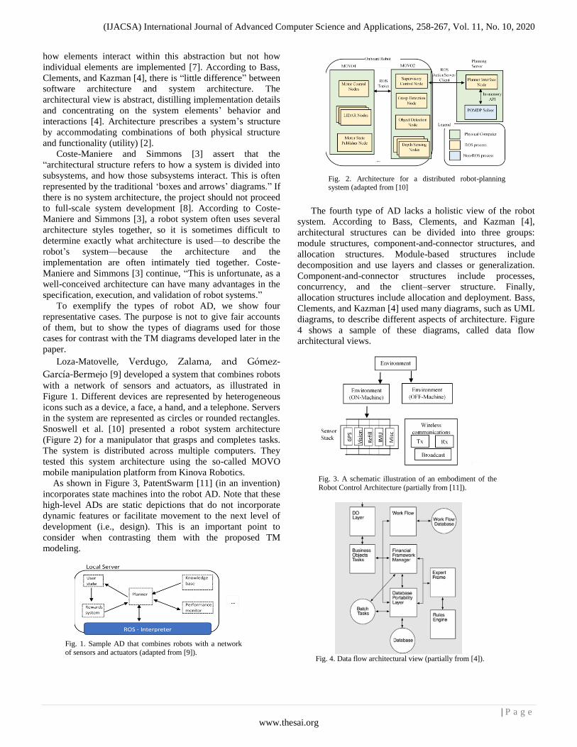
Snoswell et al. [10] presented a robot system architecture
(Figure 2) for a manipulator that grasps and completes tasks.
The system is distributed across multiple computers. They
tested this system architecture using the so-called MOVO
mobile manipulation platform from Kinova Robotics.
As shown in Figure 3, PatentSwarm [11] (in an invention)
incorporates state machines into the robot AD. Note that these
high-level ADs are static depictions that do not incorporate
dynamic features or facilitate movement to the next level of
development (i.e., design). This is an important point to
consider when contrasting them with the proposed TM
modeling.
The fourth type of AD lacks a holistic view of the robot
system. According to Bass, Clements, and Kazman [4],
architectural structures can be divided into three groups:
module structures, component-and-connector structures, and
allocation structures. Module-based structures include
decomposition and use layers and classes or generalization.
Component-and-connector structures include processes,
concurrency, and the client–server structure. Finally,
allocation structures include allocation and deployment. Bass,
Clements, and Kazman [4] used many diagrams, such as UML
diagrams, to describe different aspects of architecture. Figure
4 shows a sample of these diagrams, called data flow
architectural views.
Fig. 2. Architecture for a distributed robot-planning system (adapted from [10]
Fig. 1. Sample AD that combines robots with a network
of sensors and actuators (adapted from [9]).
Fig. 4. Data flow architectural view (partially from [4]).
Fig. 3. A schematic illustration of an embodiment of the
Robot Control Architecture (partially from [11]).
(IJACSA) International Journal of Advanced Computer Science and Applications, 258-267, Vol. 11, No. 10, 2020
| P a g e
www.thesai.org
III. RESEARCH PROBLEM AND PROPOSED SOLUTION
The samples presented in the previous section demonstrate
the need for an AD that reduces ambiguity and
misunderstandings (e.g., via consistent model usage), manages
complexity (e.g., via abstraction, with only the salient features
presented), and affords assurance (i.e., correct interpretation)
[2]. Bass, Clements, and Kazman‘s [4] representation of AD
systems can be criticized as over-described when using a
version of Occam‘s razor indicating that things should not be
multiplied without necessity. In general, current architecture
specifications might vary and lead to various difficulties,
including mixing architectural specifications with
implementation issues. Such descriptions lack the qualities of
being systemic and coherent, as well as technical-related
forms (vs. drawings of physical layouts and structural
compositions in housing). Many system architectures use
icons (e.g., faces, hands, computer screens) without a
reasonable level of detail. Additionally, a variety of languages
exist for eliciting requirements (e.g., object-oriented analyses
use scenarios or ―use cases‖ to embody requirements) and
finite-state-machine models [4] that are susceptible to
inconsistency (e.g., multiplicity of diagrams in UML and
SysML). From the modeling point of view, such
representations mix static modeling with dynamism that
incorporates time. The difference between staticity and
dynamism will become clearer when we discuss our method
of modeling robot architecture.
On the other hand, for a robot architecture to be effective
as the backbone of a project‘s design, the architecture‘s
documentation should be informative, unambiguous, and
readable by many people with various backgrounds [4]. We
will show that our TM AD (called the static model, denoted by
S) can be specified by a single ontological element called the
thimac (things/machines). S is decomposed to produce sub-
diagrams that can be converted to events by infusing a time
element into the model. The events‘ chronology models the
system‘s behavior.
Before applying TM to robot architecture specification, the
next section provides a summary review of TMs. TM
modeling is a promising modeling approach that has been
applied in diverse areas such as designing unmanned aerial
vehicles [12], documenting computer networks [13], modeling
network architectures [14], modeling advanced persistent
threats [15], modeling an IP phone communication system
[16], and programming [17]. The TM model can also be used
to model service-oriented systems [18], business systems [19],
a tendering system [20], a robot‘s architectural structure [21],
the VLSI engineering process [22], physical security [23], the
privacy of the processing cycle for bank checks [24], a small
company process [25], wastewater treatment controls [26],
asset-management systems [27], IT processes using Microsoft
Orchestrator [28], digital circuits [29], and automobile
tracking systems [30].
IV. THINGING MACHINE MODELING
According to the IEEE-RAS (Robotics and Autonomous
Systems) working group on ontologies for robotics and
automation, with the growing complexity of behaviors that
robots are expected to perform, the need for well-defined
knowledge representation is becoming more evident [31]. In
this context, ontologies are defined as ―[consisting of] a
formal conceptualization of the knowledge representation and
[providing] the definitions of the concepts and relations
capturing the knowledge of a domain in an interoperable way‖
[32]. Examples of such ontologies include those of Cheng et
al. [33]: device (e.g., concepts such as that of a machine),
process (e.g., operations performed by technical equipment),
parametric (e.g., quality of service), and product ontologies
(e.g., product information). Engel, Greiner, and Seifert [34]
proposed ontologies for batch process plants that include
operations, architectures, and general system characteristics
and relations.
In this paper, we orient our research toward a more generic
conceptualization of ontologies‘ role in robotics. An ontology
is a crucial mechanism with which to model a robot system
and its activities. A model refers to a conceptual description of
a robot system and its processes. Developing such a model
restrains and guides the robot system‘s design, development,
and use. The issue, in this context, is a cross-area study
between modeling and ontology in robotics. This paper
provides a broad ontological foundation for conceptual
modeling in the robotics domain by suggesting a practical
ontology in terms of the notion of TMs. TM modeling uses a
one-category ontology called a thimac in contrast to objects,
attributes, and relations in the object-oriented paradigm. In
philosophy, tropes are a well-known one-category ontology.
According to Cheng et al. [32], ―One-category ontologies are
deeply appealing, because their ontological simplicity gives
them an unmatched elegance and sparseness.‖
Let a thimac be denoted by ∆; then, ∆ = (M. T), where ∆
has a dual mode of being: a machine denoted as M and a thing
denoted by T. Figure 5 shows a general form of TM modeling
machines, and Figure 6 is a simplification of Figure 5. M
includes generic actions described as follows. A sample of the
two sides of a thimac will be given later.
Fig. 5. The thinging machine, M.
]).
Fig. 6. Simplification of machine, M.

(IJACSA) International Journal of Advanced Computer Science and Applications, 258-267, Vol. 11, No. 10, 2020
| P a g e
www.thesai.org
The actions (also called stages) in M (Figure 5) can be
described as follows:
Arrival: A thing reaches a new machine.
Acceptance: A thing is allowed to enter the machine. If
arriving things are always accepted, then arrival and
acceptance can be combined into a ―receiving‖ stage. For
simplicity, we will assume that a receiving stage exists.
Processing (alteration): A thing undergoes modifications
without creating a new thing.
Release: A thing is marked as ready to be transferred
outside of the machine.
Transference: A thing is input or output outside of or
within the machine.
Creation: A new thing is born (created) within a machine.
Creation can designate bringing into existence (e.g., ∃ in
logic) in the system because what exists is what is found.
Creation in M indicates ―there is‖ in the system, but not at
any particular time.
The TM model also includes the notion of triggering,
which connects two sub-diagrams between which there is no
flow. Triggering is represented by dashed arrows in the TM
diagram.
To informally justify the five TM actions, consider a
robot‘s actions. The robot interacts with the environment either
through inputting or outputting. Through its interface
(transfer), it receives things (e.g., data or actions) and outputs
(transfers) things (e.g., data or sound). Some of these output
things might be ―stocked‖ (released), waiting until the right
time for output. Accordingly, the transfer, receive, and release
actions are all types of interactions with the outside, which are
usually referred to as sending data, receiving actions (e.g.,
physical hits), outputting movement (e.g., walking to a certain
position), etc. Additionally, the robot might process incoming
things such as converting a signal to data, analyzing a scene,
inspecting a sound, and so on. It also could create (generate,
produce) things such as a sound, movement, or plan. All
activities can be specified in terms of the five actions—create,
process, release, transfer, and receive—or a subset of these
actions.
V. EXAMPLE: A WINDOW-OPENING ROBOT
Cassinis [35] developed a robot that, when given the goal ―open the window,‖ could perform the following sequence of steps: (1) locate the window, (2) reach near the window, (3) locate the handle, (4) reach the handle, (5) turn the handle, and (6) pull the handle.
A. The Static TM Model
Figure 7 shows the TM model S of this window-opening task. We assume that the window‘s location is communicated by a sensor and that the handle position is recognized through a camera on the robot. Upon being activated to open a window, the robot receives
data about the window‘s location (circle 1 in the figure) and
processes the data (2) to trigger (3) the window position‘s
generation (4). The window position and robot‘s current
position (5) both flow (6 and 7) to be processed (8), triggering
(9) the creation of a description of the path to reach the window
(10). This path flows (11) to the wheel control (12), where the
path data are processed (13) to generate movement (14) toward
the window. Upon reaching the window (15), two triggering
actions occur:
The robot‘s new location replaces its current location (16
and 17).
The camera is turned on to search for the handle (18 and
19).
Upon collecting the data about the handle (20), the handle
position is recognized and processed (21). Such a process
triggers the creation (22) of the required trajectory to reach the
handle (23), which flows (24) to the handle (25). There, the
trajectory is processed (26) to trigger the handle‘s movement
(27) to perform the following:
Turning the handle (28) and
Pulling it (29).
Note that TMs are applied uniformly for all types of
things: data, processes, wheels, handles, camera, movement,
pulling, and turning. Every machine is constructed from the
create, process, release, transfer, and receive actions, or from
a subset of these actions. Model S is richer than the so-called
ADs; however, if we are interested in the system in terms of
its components and their relations, then these can be
extracted from S by eliminating the actions, as shown in
Figure 8. Every component in Figure 8 is a thimac. To
illustrate the notion of thimac, Figure 9 shows the window-
opening robot as a thimac. It is a machine and a thing
simultaneously. For example, as a thing, it can include its
physical attributes, manufacturer, etc., as in the case of a
class‘s attributes in the object-oriented model. In addition, as
a thing, it can be shipped, cleaned, etc.
Fig. 7. Static TM Model, S

(IJACSA) International Journal of Advanced Computer Science and Applications, 258-267, Vol. 11, No. 10, 2020
| P a g e
www.thesai.org
Alternatively, if we want to go in the opposite direction into
the model‘s fine details, we can apply the same TM machine to the subthimacs. Suppose that we add an obstacle in the path to the window. Figure 10 shows the needed modifications to the original model S (Figure 7).
The modification starts in the wheels machine, where the original path to the window (circle 1) reaches the wheels‘ controller to be processed (2), triggering a movement (3) to reach the window (4). Suppose the movement instead meets an obstacle (5), which triggers (6) a warning. The warning flows (7) to a control module, which processes it (8) to trigger,
(a) activating a camera on the robot (9) and (b) saving the current path in storage (10 and 11) to continue later after overcoming the obstacle. The camera data (12) are analyzed (13) to trigger the creation of a new path (14). The new path flows to the wheels system (15), where it is processed to create movement. After the obstacle is overcome (16), the path to the window is restored (17).
B. The Dynamic Model
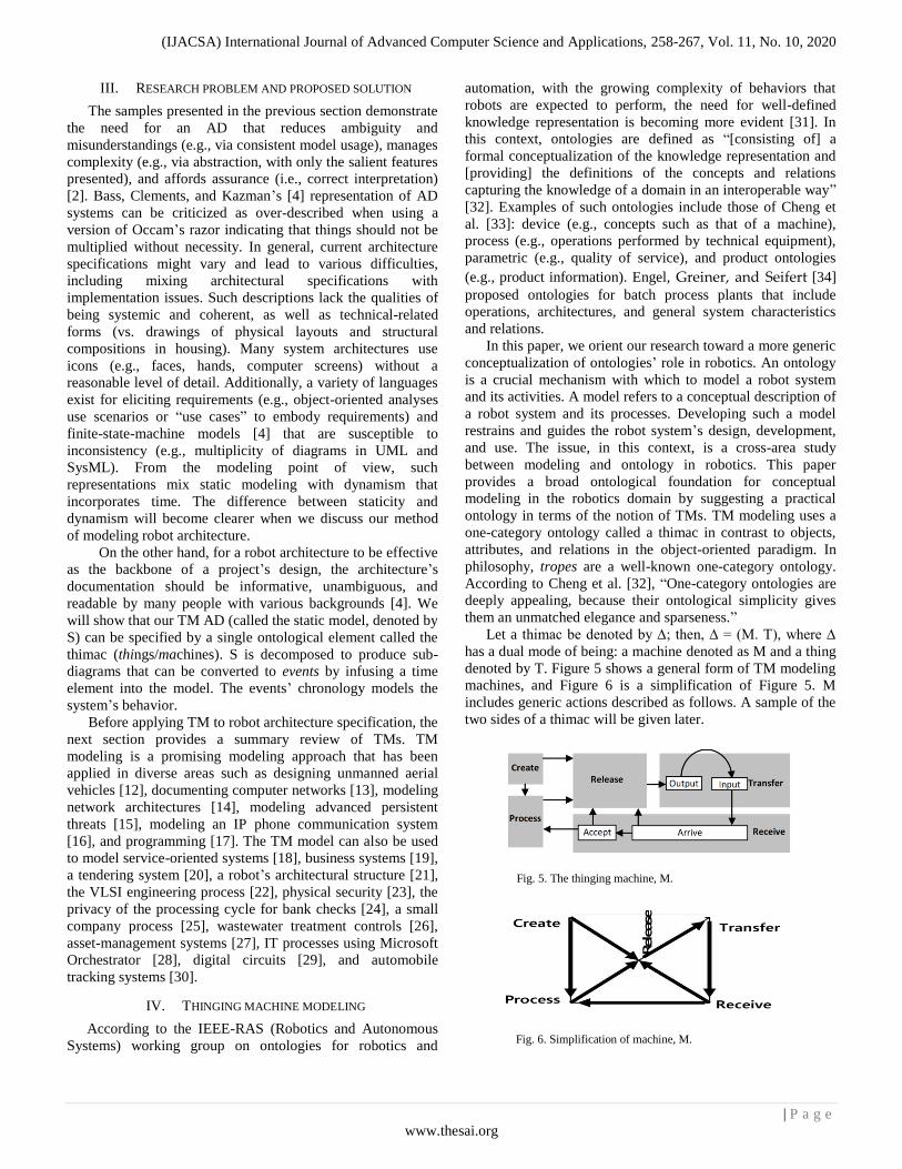
S is a machine schema that can be decomposed to generate a new organizational level (multiplicity) from the ―meaningful‖ parts of S. Model S (Figure 7) is a static description that represents a still or resting (no time) condition. The meaningfulness of a part of S resides in the isomorphism between the part and the thing it is supposed to represent (in the modeler‘s conceptual framework). Decomposition is necessary because the system described by S is clearly ―activated‖ behaviorally, piece by piece (sub-diagrams). Figure 11 shows a selected division of S for the robot system in 15 static changes. The robot‘s dynamism originates from conceptually dividing it as a whole and replacing it with its 15 sub-diagrams, which then become viewed as events by injecting a time sub-machine into each of them. For example, the event Replace the old robot location with the current location is modeled as shown in Figure 12. The chronology of events is shown in Figure 13.
Fig. 8. The window-opening robot as components and their relationships.
The window opening robot (Thimac) Machine
Thing
Create Manifest
Window data from sensor
Path to reach window
On
Current location of
the robot
Window location
Robot wheels
Handle data
Camera State
Handle position Trajectory to handle
Hand Movement to reach Movement to turn Movement to pull
Movement
Sensor
Window
data
On Robot wheels
Handle data
Camera State
Handle position
Trajectory to handle
Hand Movement to reach
Movement to turn
Movement to pull
Movement
Path to reach window
Window data from sensor
Current location of
the robot Window location
Fig. 9. The window-opening robot as a thimac.
1 15
Process: overcome obstacle
Robot wheels
Movement
Create
Original path
Create
Process
Process Create
Process
Receive Transfer
Transfer
Release
Transfer
Receive
Process: Reach an obstacle
Movement
Create
Process
Release Transfer Storage
Release Transfer
Process: Reach window
Movement
Create
Transfer
Release
Receive
Transfer
Obstacle
Report
Now path to
avoid the
obstacle
Activate
camera
Data from
camera
11
10
16
5
4
6
3
17
7
9
12
8
13
14
2
Control
Fig. 10. Adding an obstacle to the window-opening robot.
(IJACSA) International Journal of Advanced Computer Science and Applications, 258-267, Vol. 11, No. 10, 2020
| P a g e
www.thesai.org
VI. CASE STUDY
For our study, without loss of generality, we selected one
architectural description for a robot called the NAO robot, the
first autonomous, programmable humanoid robot created by
SoftBank Group. It is an effective programming tool used in
education and research. In addition, companies and health care
centers might use it to welcome, inform, and entertain visitors
[36]. NAO‘s documentation and user guide show how to start
the robot and describe the result of turning the robot ON. In
addition, they describe what happens when someone
approaches the robot [37]. Furthermore, the robot‘s actions
can be created and modified using the Choregraphe software.
Choregraphe is a multiplatform desktop application that
allows users to create animations and dialogues for robots. It
also permits users to monitor and control the robot [36]. In
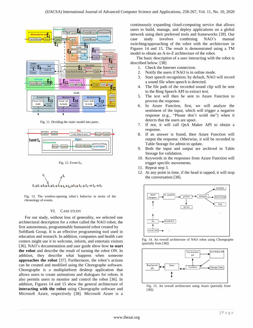
addition, Figures 14 and 15 show the general architecture of
interacting with the robot using Choregraphe software and
Microsoft Azure, respectively [38]. Microsoft Azure is a
continuously expanding cloud-computing service that allows
users to build, manage, and deploy applications on a global
network using their preferred tools and frameworks [39]. Our
case study involves combining NAO‘s manual
switching/approaching of the robot with the architecture in
Figures 14 and 15. The result is demonstrated using a TM
model to obtain an A-to-Z architecture of the robot.
The basic description of a user interacting with the robot is
described below: [38]
1. Check the Internet connection.
2. Notify the users if NAO is in online mode.
3. Start speech recognition; by default, NAO will record
a sound file when speech is detected.
4. The file path of the recorded sound clip will be sent
to the Bing Speech API to extract text.
5. The text will then be sent to Azure Function to
process the response.
6. In Azure Function, first, we will analyze the
sentiment of the input, which will trigger a negative
response (e.g., ―Please don‘t scold me‖) when it
detects that the users are upset.
7. If not, it will call QnA Maker API to obtain a
response.
8. If an answer is found, then Azure Function will
output the response. Otherwise, it will be recorded in
Table Storage for admin to update.
9. Both the input and output are archived in Table
Storage for validation.
10. Keywords in the responses from Azure Function will
trigger specific movements.
11. Repeat step 3.
12. At any point in time, if the head is tapped, it will stop
the conversation [38].
Fig. 13. The window-opening robot‘s behavior in terms of the
chronology of events.
Fig. 11. Dividing the static model into parts.
Fig. 12. Event E8.
Fig. 14. An overall architecture of NAO robot using Choregraphe (partially from [38])
Fig. 15. An overall architecture using Azure (partially from [38])

(IJACSA) International Journal of Advanced Computer Science and Applications, 258-267, Vol. 11, No. 10, 2020
| P a g e
www.thesai.org
A. TM Static Model
The robot consists of four parts: the sensors, the controller,
the microphone, and the physical parts of the robot (head and
body).
Through the sensors, the user generates a signal (circle 1)
that flows (2) to the robot to trigger the robot‘s state to be
ON (3). Switching the robot ON triggers two actions: The
LEDs are switched ON (4), and sound is created (5).
When the LEDs are switched ON, the black-and-white
light module creates (6) blinking, and a process (7) takes
its course, changing color from black to white.
Continuing at circle (5), a greeting sound is generated (8).
Approaching the robot: A talking distance (assuming a
maximum of 1.5 meters) is assumed to be initialized for
the first time using the robot (9). When the user walks
within this distance (10), a current distance is created (11)
by the sensor, and its value flows (12) to the controller,
where it is processed (13) to trigger (14) creation of the
navy color (15) on the LEDs.
Interacting with the robot: Once the user speaks (16—
bottom-left corner of the figure), this act is detected (17)
by the sensors and processed (18) to create (19) digital
data from the analog sound. The digital data flow to the
controller, where the data are processed to be recorded
(20) and stored (21). Later, the stored data are retrieved
and extracted as text (22) to create (23) sound clips. The
sound clip is processed (24) to create (identify) its
function (as a question or order).
If the function is a question (25), it flows to be processed
(26) such that:
- The question is compared with the questions stored in
the database.
(i) If the question is found, the answer is retrieved
(27) and flows to the microphone (28) to be
processed (29). Accordingly, the corresponding
speech is created (30).
(ii) Otherwise, the question is stored in a database for
validation (31).
If the function is an order (32), the order flows to the
physical head and body (33) to be processed (34). Based
on the type of order, a physical action is performed as
follows:
I. Head shaking (35),
II. Wiping forehead (36), or
III. Pointing (37) in a certain direction.
Interruption: At any moment, the user can tap the robot‘s
head (38—bottom left), which generates a signal (39)
from the tactile head sensors that flows (40) to the
microphone. The signal is processed (41) to trigger
stopping of the speech (42).
Figure 16 shows the TM model of the NAO robot‘s
architecture.
B. The Dynamic Model
The decomposition of the S model forms the foundation upon which to understand events. The resulting parts of S should be sufficiently ―meaningful.‖ The meaningfulness of a part of S resides in the isomorphism between the part and the thing it is supposed to represent (in the modeler‘s conceptual framework). For example, ―release‖ by itself as a sub-diagram does not seem to have this meaningfulness, but ―release, transfer, transfer, and receive‖ is an ideal whole/part because it corresponds to the familiar notion of ―moving from… to…‖ The resulting TM states (parts of S) are altered by inducing time (the time subthimac) to be transformed into events.
To construct the dynamic model, we identify the following
events (see Figure 17):
Event 1 (E1): The user presses the start button and creates a
signal through the sensors.
Event 2 (E2): The signal triggers the robot to be switched ON,
which causes (i) the LEDs to blink, (ii) a greeting sound, and
(iii) initialization of the talking distance.
Event 3 (E3): The user approaches the robot within 1.5 m,
which triggers creation of the current approaching distance.
Event 4 (E4): The current distance flows to the controller.
Event 5 (E5): The controller processes the current distance,
and the LED light changes to navy.
Event 6 (E6): The user speaks, which is received by the sensor.
Event 7 (E7): The analog sound is processed and converted to
digital data.
Event 8 (E8): The digital data are released to the controller,
where the data are stored.
Event 9 (E9): The digital data are retrieved and extracted as
text, then processed to create sound clips.
Event 10 (E10): The sound clips are processed to trigger
creation (identification) of the function.
Event 11 (E11): The function is processed to distinguish a
question from an order.
Event 12 (E12): The function is a question, which is sent to the
Q&A module.
Event 13 (E13): The answer to the question is sent to the
microphone.
Event 14 (E14): The answer cannot be found; hence, it is
stored.
Event 15 (E15): The function is an order; hence, it is sent to the
control of the physical body and head.
Event 16 (E16): The order is processed.
Event 17 (E17): The order is for the robot to shake its head.
Event 18 (E18): The order is for the robot to wipe its forehead.
Event 19 (E19): The order is for the robot to point.
Event 20 (E20): The user taps the robot‘s head, creating a
signal that is received by the microphone, thus stopping the
sound.
Lastly, the robot‘s behavior can be specified by the
chronology of events shown in Figure 18.

(IJACSA) International Journal of Advanced Computer Science and Applications, 258-267, Vol. 11, No. 10, 2020
| P a g e
www.thesai.org

(IJACSA) International Journal of Advanced Computer Science and Applications, 258-267, Vol. 11, No. 10, 2020
| P a g e
www.thesai.org
VII. CONCLUSION
This paper contributes to establishing a broad foundation
for describing a high-level specification of robot systems. This
involved developing the system, from static modeling to
identifying the system‘s behavior. Our approach to present the
benefits of such an approach was to contrast current
architectural descriptions (Figures 1-4 and 14-15) with static
and dynamic TM modeling to obtain a more detailed structure
of the robot‘s processes, which is important to complete the
designing and implementing phases of any robot structure.
Further research will apply TM modeling to different aspects
in robotics.

(IJACSA) International Journal of Advanced Computer Science and Applications, 258-267, Vol. 11, No. 10, 2020
| P a g e
www.thesai.org
REFERENCES [1] D. Kortenkamp and R. Simmons, ―Robotic systems architectures and
programming,‖ in Springer Handbook of Robotics, B. Siciliano and O. Khatib, Eds. Berlin, Germany: Springer, 2008, pp. 187–206.
[2] R. England, ―Elements of (system) architecture—an introduction, v1.0,‖ Project: Human Centric Systems Engineering, 2016. DOI: 10.13140/RG.2.2.31541.78566
[3] E. Coste-Maniere and R. Simmons, ―Architecture, the backbone of robotic systems,‖ Proceedings of the 2000 IEEE International Conf. on Robotics & Automation. San Francisco, CA, USA, April 2000, pp. 67–72.
[4] L. Bass, P. Clements, and R. Kazman, Software Architecture in Practice, 2nd ed. Addison Wesley, 2003.
[5] F. Brooks, ―Architectural philosophy,‖ in Planning a Computer System - Project Stretch, W. Buchholz, Ed. New York: McGraw-Hill, 1962, pp. 5–16.
[6] G. Amdahl, G. Blaauw, and F. Brooks, ―Architecture of the IBM System/360,‖ IBM Journal of Research and Development, vol. 8, pp. 87–101, 1964.
[7] M. T. Long, Creating a distributed field robot architecture for multiple robots. (2004). Ph.D. Thesis, University of San Francisco, San Francisco, CA, USA, 1 November 2004. https://scholarcommons.usf.edu/etd/1137
[8] Workshop on Architectures for Software Systems, School of Computer Science, Carnegie Mellon University, Pittsburgh, PA, USA, April 1995. CMU-CS-TR-95-151.
[9] D. Loza-Matovelle, A. Verdugo, E. Zalama, and J. Gómez-García-Bermejo, ―An architecture for the integration of robots and sensors for the care of the elderly in an ambient assisted living environment,‖ Robotics, vol. 8, 2019.
[10] A. J. Snoswell, V. Dewanto, M. Hoerger, J. Song, H. Kurniawati, and S. P. N. Singh, ―A distributed, any-time robot architecture for robust manipulation,‖ Australasian Conference on Robotics and Automation, Lincoln, New Zealand, December 4-6, 2018.
[11] PatentSwarm, Control architecture for multi-robot system US 9 527 211B2, INVENTION Claim. Available online: https://patentswarm.com/patents/US9527211B2 (accessed July 7, 2020).
[12] S. Al-Fedaghi and J. Al-Fadhli, ―Thinging-oriented modeling of unmanned aerial vehicles,‖ Int. J. Adv. Comput. Sci. Applic., vol. 11, pp. 610–619, 2020. DOI: 10.14569/IJACSA.2020.0110575
[13] S. Al-Fedaghi and B. Behbehani, ―How to document computer networks,‖ Journal of Computer Science, vol. 16, pp. 423–434, 2020.
[14] S. Al-Fedaghi and D. Al-Qemlas, ―Modeling network architecture: A cloud case study,‖ IJCSNS, vol. 20, pp. 195–209, 2020.
[15] S. Al-Fedaghi and M. Bayoumi, ―Modeling advanced persistent threats: A case study of APT38,‖ 14th International Conference for Internet Technology and Secured Transactions (ICITST-2019), London, UK, December 9-11, 2019.
[16] S. Al-Fedaghi and G. Aldamkhi, ―Conceptual modeling of an IP phone communication system: A case study,‖ 18th Annual Wireless Telecommunications Symposium (WTS 2019), New York City, New York, USA, April 9-12, 2019.
[17] S. Al-Fedaghi and E. Haidar, ―Programming is diagramming is programming,‖ J. Software, vol. 14, pp. 410–422, 2019.
[18] S. Al-Fedaghi and M. Al-Otaibi, ―Service-oriented systems as a thinging machine: A case study of customer relationship management,‖ IEEE Intern. Conf. on Information and Computer Technologies, University of Hawaii, Maui College, Hawaii, USA, March 14-17, 2019, pp. 243–254.
[19] S. Al-Fedaghi and M. Makdessi, “Modeling business process and events,‖ 9th Computer Science On-line Conference, Springer, Applied Informatics and Cybernetics in Intelligent Systems, April 23-26, 2020, pp. 83–97. doi.org/10.1007/978-3-030-30329-7_8
[20] S. Al-Fedaghi and E. Haidar, ―Thinging-based conceptual modeling: Case study of a tendering system,‖ Journal of Computer Science, vol. 16, pp. 452–466, 2020. DOI: 10.3844/jcssp.2020.452.466
[21] S. Al-Fedaghi and M. Al-Saraf, “Thinging the robotic architectural structure,‖ The 3rd Intern. Conf. on Mechatronics, Control and Robotics, Tokyo, Japan, Feb. 22-24, 2020.
[22] S. Al-Fedaghi and A. Hassouneh, ―Modeling the engineering process as a thinging machine: A case study of chip manufacturing,‖ The 8th Computer Science On-line Conference, April 24, 2019. L pp. 67–77.
[23] S. Al-Fedaghi and O. Alsumait, ―Toward a conceptual foundation for physical security: Case study of an IT department,‖ International Journal of Safety and Security Engineering, vol. 9, pp. 137–156, 2019.
[24] S. Al-Fedaghi and M. Alsulaimi, ―Privacy thinging applied to the processing cycle of bank cheques,‖ 3rd International Conference on System Reliability and Safety, Barcelona, Spain, Nov. 24-26, 2018.
[25] S. Al-Fedaghi and H. Aljenfawi, ―A small company as a thinging machine,‖ 10th International Conference on Information Management and Engineering (ICIME 2018), University of Salford, Manchester, UK, September 22-24, 2018, pp. 27–34. doi.org/10.1145/3285957.3285988
[26] S. Al-Fedaghi and R. Al-Azmi, ―Control of waste water treatment as a flow machine: A case study,‖ The 24th IEEE International Conference on Automation and Computing (ICAC‘18), Newcastle University, Newcastle upon Tyne, UK, September 6-7, 2018.
[27] S. Al-Fedaghi and N. Al-Huwais, ―Toward modeling information in asset management: Case study using Maximo, 2018,‖ 4th International Conf. on Information Management, Oxford, UK, 2018, pp. 117–124.
[28] S. Al-Fedaghi and M. Alsharah, ―Modeling IT processes: A case study using Microsoft Orchestrator,‖ 2018 International Conference on Advances in Computing and Communication Engineering (ICACCE), Paris, France, June 22-23, 2018, pp. 394–401.
[29] S. Al-Fedaghi and A. Esmaeel, ―Modeling digital circuits as machines of things that flow,‖ 2018 International Conference on Mechatronics Systems and Control Engineering (ICMSCE 2018), Amsterdam, Netherlands, February 21-23, 2018.
[30] S. Al-Fedaghi and Y. Atiyah, ―Tracking systems as thinging machine: A case study of a service company,‖ IJACSA, vol. 9, pp. 110–119, 2018.
[31] C. Schlenoff, E. Prestes, R. Madhavan, P. Goncalves, H. Li, S. Balakirsky, T. Kramer, and E. Miguelanez, ―An IEEE standard ontology for robotics and automation,‖ IEEE/RSJ International Conference on Intelligent Robots and Systems, Vilamoura, Portugal, Oct. 7-12, 2012.
[32] V. R. S. Kumar, A. Khamis, S. Fiorini, J. L. Carbonera, A. O. Alarcos, M. Habib, P. Goncalves, H. Li, and J. I. Olszewska, ―Ontologies for industry 4.0.,‖ The Knowledge Engineering Review, vol. 34, e17, 2019. DOI: 10.1017/S0269888919000109
[33] H. Cheng, P. Zeng, L. Xue, Z. Shi, P. Wang, and H. Yu, ―Manufacturing ontology development based on industry 4.0 demonstration production line,‖ IEEE International Conference on Trustworthy Systems and Their Applications, Wuhan, China, September 22-23, 2016, pp. 42–47.
[34] G. Engel, T. Greiner, and S. Seifert, ―Ontology-assisted engineering of cyber-physical production systems in the field of process technology,‖ IEEE Trans. on Industrial Informatics, vol. 14, pp. 2792–2802, 2018.
[35] R. Cassinis, BARCS: A new way of building robots. Laboratorio di Calcolatori, Dipartimento di Elettronica, Politecnico di Milano, Milan, Italy, September 1987. Available online: http://www.cassinis.it/Siti%20ex%20Uni/ARL/docs/papers/05_002.pdf
[36] X. Lacherade, SoftBank Robotics Europe – SAS (Limited Company). 2020. Available online: https://www.softbankrobotics.com/emea/index.php/en/nao (accessed on July 10, 2020).
[37] SoftBank Robotics Europe. Aldebaran documentation. 2017. Available online: http://doc.aldebaran.com/2-1/home_nao.html (accessed on July 10, 2020).
[38] M. T. G. Ying, NaoRobot. November 2017. Available online: https://github.com/guangying94/NaoRobot#start-of-content (accessed on July 10, 2020).
[39] Microsoft. Microsoft Azure. 2020. Available online: https://azure.microsoft.com/en-us/overview/ (accessed on July 10, 2020)


![Context Aware Robot Architecture, Application to the … · 2020-05-18 · Other middlewares, as [7], focus on tasks description language and life cycles. To build a generic architecture,](https://img.pdfslide.us/doc/110x75/5f9369188ae2c6651f34bdca/context-aware-robot-architecture-application-to-the-2020-05-18-other-middlewares.jpg)


![Robot Boats as a Mobile Aquatic Sensor Networklowkh/pubs/essa2009.pdf · software architecture and system called Multilevel Au-tonomy Robot Telesupervision Architecture (MARTA) [11]](https://img.pdfslide.us/doc/110x75/603d4100ddef000db6527ff2/robot-boats-as-a-mobile-aquatic-sensor-network-lowkhpubs-software-architecture.jpg)