Embed Size (px)
Citation preview
Instruction manual
High Intensity LED Stroboscope Digital Tachometer
DT-361/365
Be sure to read before use.
Before use, please carefully read these safety precautions as well as instructions,and follow them for proper use.
98585F
2
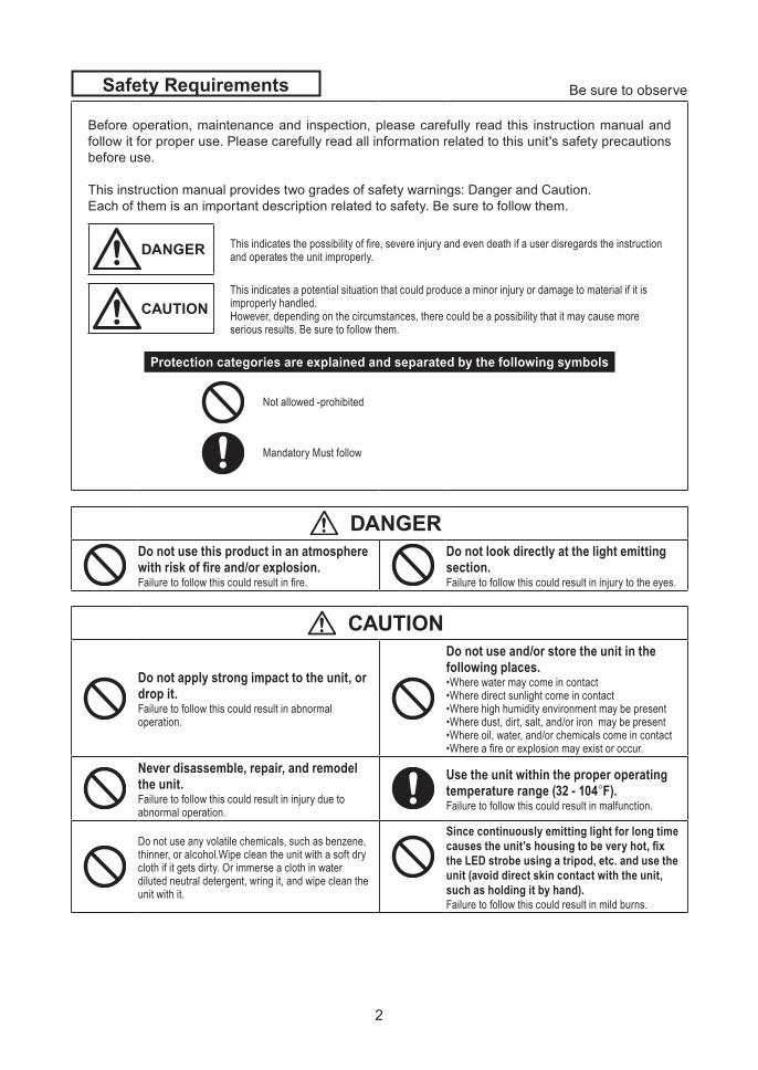
Safety Requirements Be sure to observe
Before operation, maintenance and inspection, please carefully read this instruction manual and follow it for proper use. Please carefully read all information related to this unit's safety precautions before use.
This instruction manual provides two grades of safety warnings: Danger and Caution.Each of them is an important description related to safety. Be sure to follow them.
DANGER This indicates the possibility of fire, severe injury and even death if a user disregards the instruction and operates the unit improperly.
CAUTIONThis indicates a potential situation that could produce a minor injury or damage to material if it is improperly handled.However, depending on the circumstances, there could be a possibility that it may cause more serious results. Be sure to follow them.
Protection categories are explained and separated by the following symbols
Not allowed -prohibited
Mandatory Must follow
DANGERDo not use this product in an atmosphere with risk of fire and/or explosion. Failure to follow this could result in fire.
Do not look directly at the light emitting section.Failure to follow this could result in injury to the eyes.
CAUTION
Do not apply strong impact to the unit, or drop it.Failure to follow this could result in abnormal operation.
Do not use and/or store the unit in the following places.•Where water may come in contact•Where direct sunlight come in contact•Where high humidity environment may be present•Where dust, dirt, salt, and/or iron may be present •Where oil, water, and/or chemicals come in contact•Where a fire or explosion may exist or occur.
Never disassemble, repair, and remodel the unit.Failure to follow this could result in injury due to abnormal operation.
Use the unit within the proper operating temperature range (32 - 104°F).Failure to follow this could result in malfunction.
Do not use any volatile chemicals, such as benzene, thinner, or alcohol.Wipe clean the unit with a soft dry cloth if it gets dirty. Or immerse a cloth in water diluted neutral detergent, wring it, and wipe clean the unit with it.
Since continuously emitting light for long time causes the unit's housing to be very hot, fix the LED strobe using a tripod, etc. and use the unit (avoid direct skin contact with the unit, such as holding it by hand).Failure to follow this could result in mild burns.
3
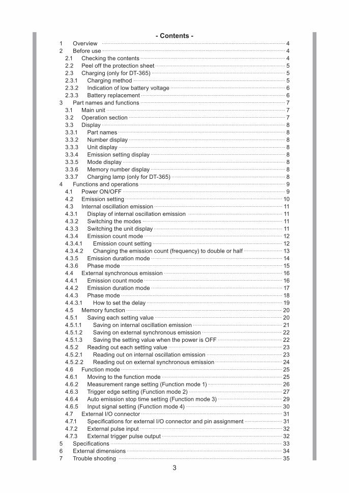
- Contents - 1 Overview 42 Before use 4
2.1 Checking the contents 42.2 Peel off the protection sheet 52.3 Charging (only for DT-365) 52.3.1 Charging method 52.3.2 Indication of low battery voltage 62.3.3 Battery replacement 6
3 Part names and functions 73.1 Main unit 73.2 Operation section 73.3 Display 83.3.1 Part names 83.3.2 Number display 83.3.3 Unit display 83.3.4 Emission setting display 83.3.5 Mode display 83.3.6 Memory number display 83.3.7 Charging lamp (only for DT-365) 8
4 Functions and operations 94.1 Power ON/OFF 94.2 Emission setting 104.3 Internal oscillation emission 114.3.1 Display of internal oscillation emission 114.3.2 Switching the modes 114.3.3 Switching the unit display 114.3.4 Emission count mode 124.3.4.1 Emission count setting 124.3.4.2 Changing the emission count (frequency) to double or half 134.3.5 Emission duration mode 144.3.6 Phase mode 154.4 External synchronous emission 164.4.1 Emission count mode 164.4.2 Emission duration mode 174.4.3 Phase mode 184.4.3.1 How to set the delay 194.5 Memory function 204.5.1 Saving each setting value 204.5.1.1 Saving on internal oscillation emission 214.5.1.2 Saving on external synchronous emission 224.5.1.3 Saving the setting value when the power is OFF 224.5.2 Reading out each setting value 234.5.2.1 Reading out on internal oscillation emission 234.5.2.2 Reading out on external synchronous emission 244.6 Function mode 254.6.1 Moving to the function mode 254.6.2 Measurement range setting (Function mode 1) 264.6.3 Trigger edge setting (Function mode 2) 274.6.4 Auto emission stop time setting (Function mode 3) 294.6.5 Input signal setting (Function mode 4) 304.7 External I/O connector 314.7.1 SpecificationsforexternalI/Oconnectorandpinassignment 314.7.2 External pulse input 324.7.3 External trigger pulse output 32
5 Specifications 336 External dimensions 347 Trouble shooting 35
4
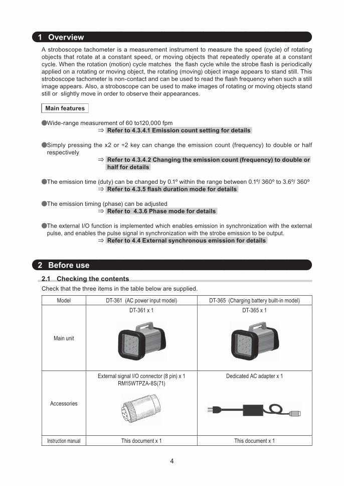
1 Overview A stroboscope tachometer is a measurement instrument to measure the speed (cycle) of rotating objects that rotate at a constant speed, or moving objects that repeatedly operate at a constant cycle.Whentherotation(motion)cyclematchestheflashcyclewhilethestrobeflashisperiodicallyapplied on a rotating or moving object, the rotating (moving) object image appears to stand still. This stroboscopetachometerisnon-contactandcanbeusedtoreadtheflashfrequencywhensuchastillimage appears. Also, a stroboscope can be used to make images of rotating or moving objects stand still or slightly move in order to observe their appearances.
Main features
Wide-range measurement of 60 to120,000 fpm Refer to 4.3.4.1 Emission count setting for details
Simply pressing the x2 or ÷2 key can change the emission count (frequency) to double or half respectively
Refer to 4.3.4.2 Changing the emission count (frequency) to double or half for details
The emission time (duty) can be changed by 0.1º within the range between 0.1º/ 360º to 3.6º/ 360º Refer to 4.3.5 flash duration mode for details
The emission timing (phase) can be adjusted Refer to 4.3.6 Phase mode for details
The external I/O function is implemented which enables emission in synchronization with the external pulse, and enables the pulse signal in synchronization with the strobe emission to be output.
Refer to 4.4 External synchronous emission for details
2 Before use2.1 Checking the contentsCheck that the three items in the table below are supplied.
M odel DT-361 (AC power input model) DT-365 (Charging battery built-in model)
Main unit
DT-361 x 1 DT-365 x 1
Accessories
External signal I/O connector (8 pin) x 1RM15WTPZA-8S(71)
Dedicated AC adapter x 1
Instruction manual This document x 1 This document x 1
5
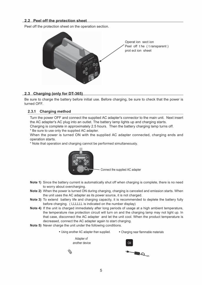
2.2 Peel off the protection sheetPeel off the protection sheet on the operation section.
O p erat i o n sect i o nP eel o f f t h e ( t ransp arent )p ro t ect i o n sh eet
2.3 Charging (only for DT-365)Be sure to charge the battery before initial use. Before charging, be sure to check that the power is turned OFF.
2.3.1 Charging methodTurn the power OFF and connect the supplied AC adapter's connector to the main unit. Next insert the AC adapter's AC plug into an outlet. The battery lamp lights up and charging starts.Charging is complete in approximately 2.5 hours. Then the battery charging lamp turns off.* Be sure to use only the supplied AC adapter.When the power is turned ON with the supplied AC adapter connected, charging ends and operation starts.* Note that operation and charging cannot be performed simultaneously.
C onnect the sup p l ied A C adap ter
Note 1) Since the battery current is automatically shut off when charging is complete, there is no need to worry about overcharging.
Note 2) When the power is turned ON during charging, charging is canceled and emission starts. When the unit uses the AC adapter as its power source, it is not charged.
Note 3) To extend battery life and charging capacity, it is recommended to deplete the battery fully before charging. ( LLLLLL is indicated on the number display)
Note 4) If the unit is charged immediately after long periods of usage at a high ambient temperature, the temperature rise protection circuit will turn on and the charging lamp may not light up. In that case, disconnect the AC adapter and let the unit cool. When the product temperature is decreased, connect the AC adapter again to start charging.
Note 5) Never charge the unit under the following conditions.
A dap ter of another dev ice
•C har g ing near f l ammab l e mater ial s •U sing another A C adap ter than sup p l ied.
O il
6
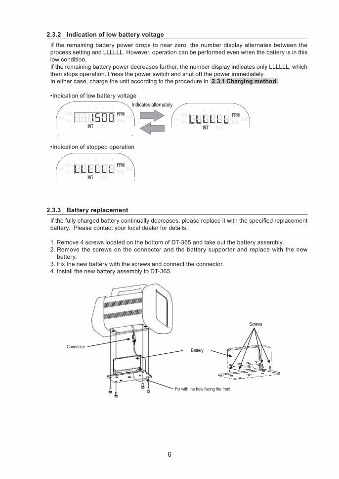
2.3.2 Indication of low battery voltageIf the remaining battery power drops to near zero, the number display alternates between the process setting and LLLLLL. However, operation can be performed even when the battery is in this low condition.If the remaining battery power decreases further, the number display indicates only LLLLLL, which then stops operation. Press the power switch and shut off the power immediately.In either case, charge the unit according to the procedure in 2.3.1 Charging method .
•IndicationoflowbatteryvoltageI ndicates al ter natel y
•Indicationofstoppedoperation
2.3.3 Battery replacementIfthefullychargedbatterycontinuallydecreases,pleasereplaceitwiththespecifiedreplacementbattery. Please contact your local dealer for details.
1. Remove 4 screws located on the bottom of DT-365 and take out the battery assembly.2. Remove the screws on the connector and the battery supporter and replace with the new
battery.3. Fix the new battery with the screws and connect the connector.4. Install the new battery assembly to DT-365.
C onnectorB attery
S crews
Fix with the hole facing the front.
7
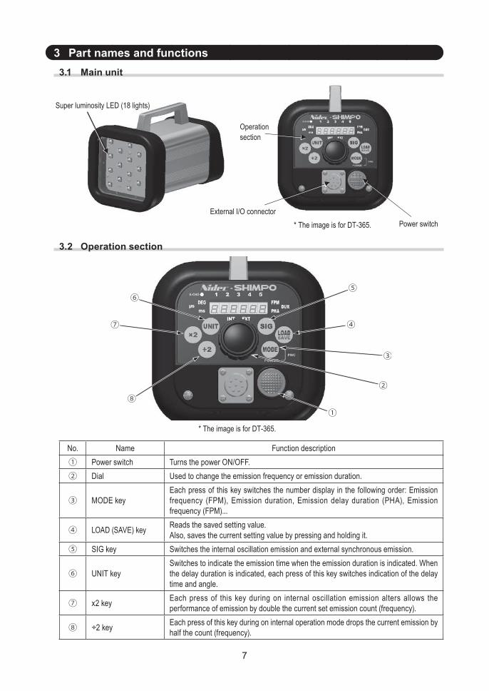
3 Part names and functions3.1 Main unit
S up er l uminosity L ED ( 1 8 l ig hts)
Pow er sw itchEx ter nal I / O connector
O p er ationsection
* T he imag e is f or D T - 3 6 5 .
3.2 Operation section
②
①
③
④
⑧
⑥
⑦
⑤
* T he imag e is f or D T - 3 6 5 .
No. Name Function description① Power switch Turns the power ON/OFF.② D ial Used to change the emission frequency or emission duration.
③ MODE keyEach press of this key switches the number display in the following order: Emission frequency (FPM), Emission duration, Emission delay duration (PHA), Emission frequency (FPM)...
④ LOAD (SAVE) key Reads the saved setting value.Also, saves the current setting value by pressing and holding it.
⑤ SIG key Switches the internal oscillation emission and external synchronous emission.
⑥ UNIT keySwitches to indicate the emission time when the emission duration is indicated. When the delay duration is indicated, each press of this key switches indication of the delay time and angle.
⑦ x2 key Each press of this key during on internal oscillation emission alters allows the performance of emission by double the current set emission count (frequency).
⑧ ÷2 key Each press of this key during on internal operation mode drops the current emission by half the count (frequency).
8
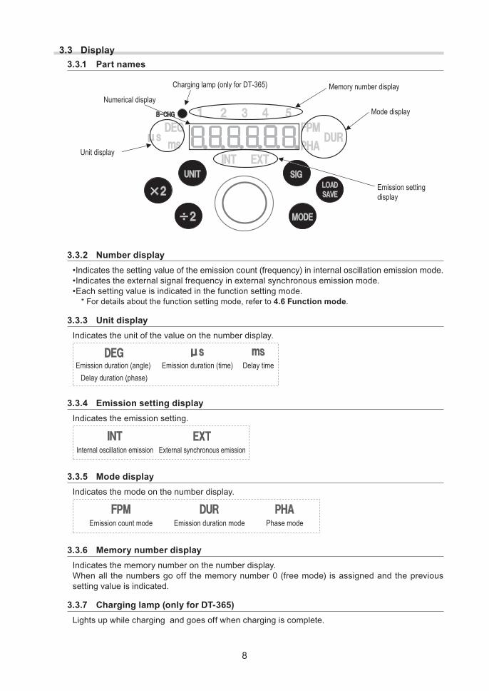
3.3 Display3.3.1 Part names
N umer ical disp l ay
U nit disp l ay
M ode disp l ay
Emission setting disp l ay
M emor y numb er disp l ayC har g ing l amp ( onl y f or D T - 3 6 5 )
3.3.2 Number display•Indicatesthesettingvalueoftheemissioncount(frequency)ininternaloscillationemissionmode.•Indicatestheexternalsignalfrequencyinexternalsynchronousemissionmode.•Eachsettingvalueisindicatedinthefunctionsettingmode.
* For details about the function setting mode, refer to 4.6 Function mode.
3.3.3 Unit displayIndicates the unit of the value on the number display.
Emission dur ation ( ang l e) D el ay dur ation ( p hase)
Emission dur ation ( time) D el ay time
3.3.4 Emission setting displayIndicates the emission setting.
I nter nal oscil l ation emission Ex ter nal sy nchr onous emission
3.3.5 Mode displayIndicates the mode on the number display.
Emission count mode Emission dur ation mode Phase mode
3.3.6 Memory number displayIndicates the memory number on the number display.When all the numbers go off the memory number 0 (free mode) is assigned and the previous setting value is indicated.
3.3.7 Charging lamp (only for DT-365)Lights up while charging and goes off when charging is complete.
9
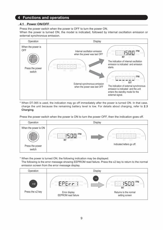
4 Functions and operations4.1 Power ON/OFFPress the power switch when the power is OFF to turn the power ON.When the power is turned ON, the model is indicated, followed by internal oscillation emission or external synchronous emission.
Operation D isplay
When the power is OFF
Press the power switch
The indication of internal oscillationemission is indicated and emission starts.
Internal oscillation emission when the power was last OFF
External synchronous emissionwhen the power was last OFF The indication of external synchronous
emission is indicated and the unit enters the standby mode for the external signal.
* When DT-365 is used, the indication may go off immediately after the power is turned ON. In that case, charge the unit because the remaining battery level is low. For details about charging, refer to 2.3 Charging.
Press the power switch when the power is ON to turn the power OFF, then the indication goes off.
Operation D isplay
When the power is ON
Press the power switch
I ndicated l etter s g o of f .
* When the power is turned ON, the following indication may be displayed.The following is the error message showing EEPROM read failure. Press the x2 key to return to the normal emission screen from the error message display.
Operation D isplay
Press the x2 key R etur ns to the nor malsetting scr een
Er r or disp l ayEEPR O M r ead f ail ur e
10
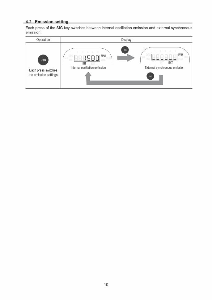
4.2 Emission settingEach press of the SIG key switches between internal oscillation emission and external synchronous emission.
Operation D isplay
Each press switches the emission settings
I nter nal oscil l ation emission Ex ter nal sy nchr onous emission
11
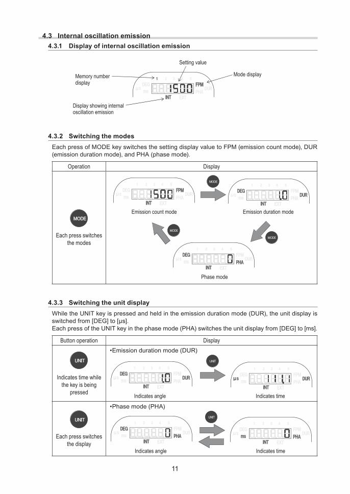
4.3 Internal oscillation emission4.3.1 Display of internal oscillation emission
S etting v al ue
M ode disp l ayM emor y numb erdisp l ay
D isp l ay show ing inter naloscil l ation emission
4.3.2 Switching the modesEach press of MODE key switches the setting display value to FPM (emission count mode), DUR (emission duration mode), and PHA (phase mode).
Operation D isplay
Each press switches the modes
Emission dur ation mode
Phase mode
Emission count mode
4.3.3 Switching the unit displayWhile the UNIT key is pressed and held in the emission duration mode (DUR), the unit display is switchedfrom[DEG]to[μs].Each press of the UNIT key in the phase mode (PHA) switches the unit display from [DEG] to [ms].
Button operation D isplay
Indicates time while the key is being
pressed
•Emissiondurationmode(DUR)
I ndicates ang l e I ndicates time
Each press switches the display
•Phasemode(PHA)
I ndicates ang l e I ndicates time
12
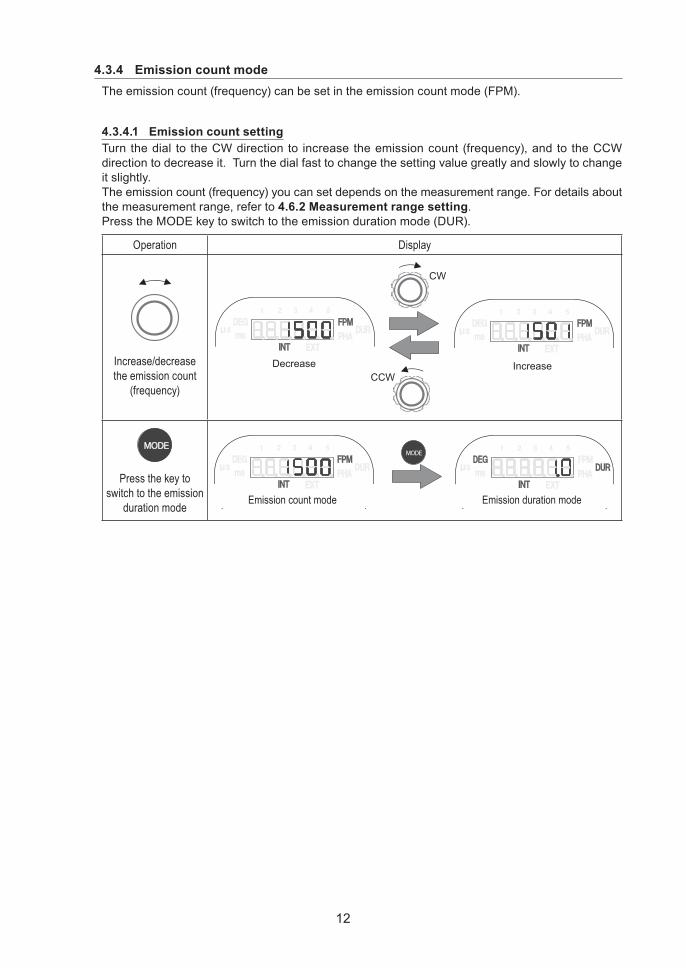
4.3.4 Emission count modeThe emission count (frequency) can be set in the emission count mode (FPM).
4.3.4.1 Emission count settingTurn the dial to the CW direction to increase the emission count (frequency), and to the CCW direction to decrease it. Turn the dial fast to change the setting value greatly and slowly to change it slightly.The emission count (frequency) you can set depends on the measurement range. For details about the measurement range, refer to 4.6.2 Measurement range setting.Press the MODE key to switch to the emission duration mode (DUR).
Operation D isplay
Increase/decrease the emission count
(frequency)
Decrease IncreaseCCW
CW
Press the key to switch to the emission
duration mode Emission count mode Emission dur ation mode
13
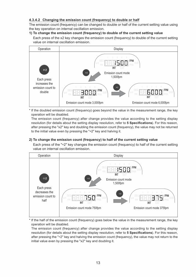
4.3.4.2 Changing the emission count (frequency) to double or halfThe emission count (frequency) can be changed to double or half of the current setting value using the key operation on internal oscillation emission.1) To change the emission count (frequency) to double of the current setting value
Each press of the x2 key changes the emission count (frequency) to double of the current setting value on internal oscillation emission.
Operation D isplay
Each press increases the
emission count to double
Emission count mode1 , 5 0 0 f p m
Emission count mode 3 , 0 0 0 f p m Emission count mode 6 , 0 0 0 f p m
* If the doubled emission count (frequency) goes beyond the value in the measurement range, the key operation will be disabled.The emission count (frequency) after change provides the value according to the setting display resolution (for details about the setting display resolution, refer to 5 Specifications). For this reason, after pressing the "x2" key and doubling the emission count (frequency), the value may not be returned to the initial value even by pressing the "÷2" key and halving it.
2) To change the emission count (frequency) to half of the current setting valueEach press of the "÷2" key changes the emission count (frequency) to half of the current setting value on internal oscillation emission.
Operation D isplay
Each press decreases the
emission count to half
Emission count mode1 , 5 0 0 f p m
Emission count mode 7 5 0 f p m Emission count mode 3 7 5 f p m
* If the half of the emission count (frequency) goes below the value in the measurement range, the key operation will be disabled.The emission count (frequency) after change provides the value according to the setting display resolution (for details about the setting display resolution, refer to 5 Specifications). For this reason, after pressing the "÷2" key and halving the emission count (frequency), the value may not return to the initial value even by pressing the "x2" key and doubling it.
14
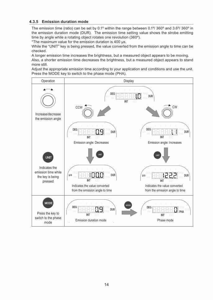
4.3.5 Emission duration modeThe emission time (ratio) can be set by 0.1º within the range between 0.1º/ 360º and 3.6º/ 360º in the emission duration mode (DUR). The emission time setting value shows the strobe emitting time by angle while a rotating object rotates one revolution (360º).*Themaximumvaluefortheemissiondurationis400μs.While the “UNIT” key is being pressed, the value converted from the emission angle to time can be checked.A longer emission time increases the brightness, but a measured object appears to be moving.Also, a shorter emission time decreases the brightness, but a measured object appears to stand more still.Adjust the appropriate emission time according to your application and conditions and use the unit.Press the MODE key to switch to the phase mode (PHA).
Operation D isplay
Increase/decrease the emission angle
Indicates the emission time while
the key is being pressed
Emission ang l e: D ecr eases Emission ang l e: I ncr eases
I ndicates the v al ue conv er tedf r om the emission ang l e to time
I ndicates the v al ue conv er tedf r om the emission ang l e to time
C W C C W
Press the key to switch to the phase
mode Emission dur ation mode Phase mode
15
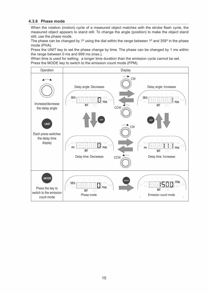
4.3.6 Phase modeWhentherotation(motion)cycleofameasuredobjectmatcheswiththestrobeflashcycle,themeasured object appears to stand still. To change the angle (position) to make the object stand still, use the phase mode.The phase can be changed by 1º using the dial within the range between 1º and 359º in the phase mode (PHA).Press the UNIT key to set the phase change by time. The phase can be changed by 1 ms within the range between 0 ms and 999 ms (max.).When time is used for setting, a longer time duration than the emission cycle cannot be set.Press the MODE key to switch to the emission count mode (FPM).
Operation D isplay
Increase/decrease the delay angle
Each press switches the delay time
display
D el ay ang l e: D ecr eases D el ay ang l e: I ncr eases
D el ay time: D ecr eases D el ay time: I ncr eases
C C W
C W
C C W
C W
Press the key to switch to the emission
count mode Phase mode Emission count mode
16
4.4 External synchronous emissionExternal synchronous emission is the function to emit a strobe flash in synchronization with an external pulse.•Toactivateexternalsynchronousemissionmode,referto4.2 Emission setting.•Theselectioncanbemadewhethertheemissionistriggeredbasedontherisingedgeoftheexternal pulse or the falling edge. Refer to 4.6.3 Trigger edge setting.•Timing(delay)fromtheexternalpulseentrytostrobeflashemissioncanbeoptionallyset.
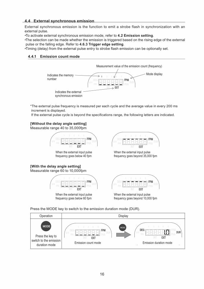
4.4.1 Emission count mode
M easur ement v al ue of the emission count ( f r eq uency )
I ndicates the ex ter nalsy nchr onous emission
M ode disp l ayI ndicates the memor ynumb er
*The external pulse frequency is measured per each cycle and the average value in every 200 ms increment is displayed. Iftheexternalpulsecycleisbeyondthespecificationsrange,thefollowinglettersareindicated.
[Without the delay angle setting]Measurable range 40 to 35,000fpm
W hen the ex ter nal inp ut p ul sef r eq uency g oes b el ow 4 0 f p m
W hen the ex ter nal inp ut p ul sef r eq uency g oes b ey ond 3 5 , 0 0 0 f p m
[With the delay angle setting]Measurable range 60 to 10,000fpm
W hen the ex ter nal inp ut p ul sef r eq uency g oes b el ow 6 0 f p m
W hen the ex ter nal inp ut p ul sef r eq uency g oes b ey ond 1 0 , 0 0 0 f p m
Press the MODE key to switch to the emission duration mode (DUR).
Operation D isplay
Press the key to switch to the emission
duration mode Emission count mode Emission dur ation mode
17
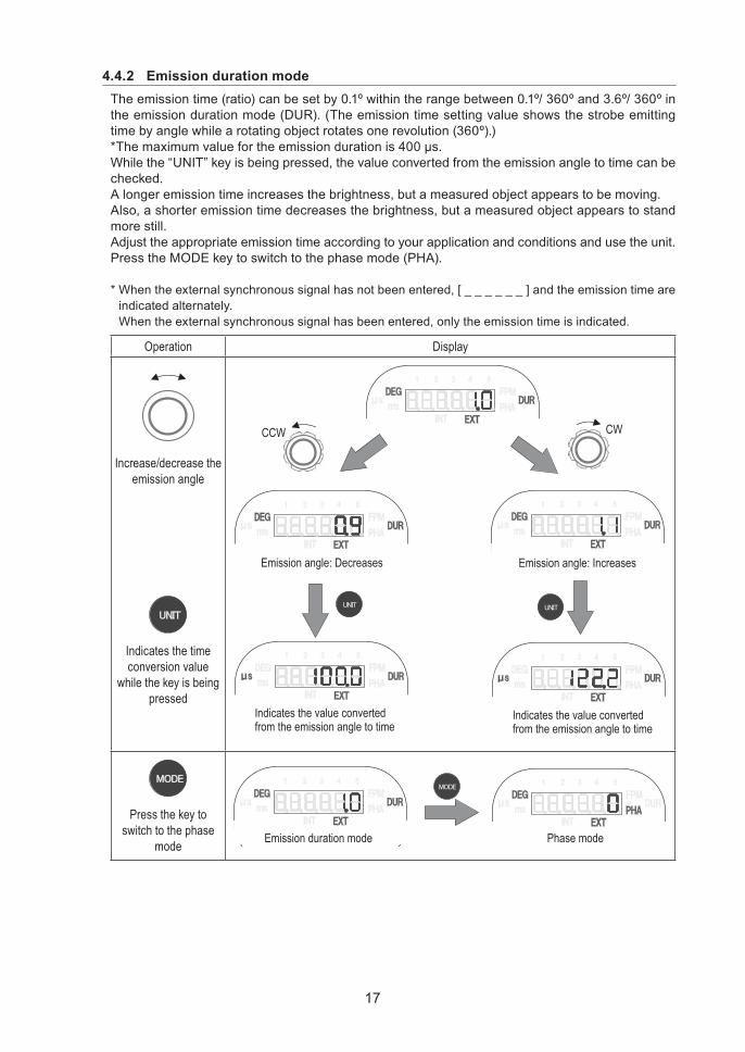
4.4.2 Emission duration modeThe emission time (ratio) can be set by 0.1º within the range between 0.1º/ 360º and 3.6º/ 360º in the emission duration mode (DUR). (The emission time setting value shows the strobe emitting time by angle while a rotating object rotates one revolution (360º).)*Themaximumvaluefortheemissiondurationis400μs.While the “UNIT” key is being pressed, the value converted from the emission angle to time can be checked.A longer emission time increases the brightness, but a measured object appears to be moving.Also, a shorter emission time decreases the brightness, but a measured object appears to stand more still.Adjust the appropriate emission time according to your application and conditions and use the unit.Press the MODE key to switch to the phase mode (PHA).
* When the external synchronous signal has not been entered, [ _ _ _ _ _ _ ] and the emission time are indicated alternately.When the external synchronous signal has been entered, only the emission time is indicated.
Operation D isplay
Increase/decrease the emission angle
Indicates the time conversion value
while the key is being pressed
Emission ang l e: D ecr eases Emission ang l e: I ncr eases
I ndicates the v al ue conv er tedf r om the emission ang l e to time
I ndicates the v al ue conv er tedf r om the emission ang l e to time
C C W C W
Press the key to switch to the phase
mode Emission dur ation mode Phase mode
18
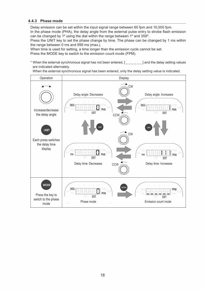
4.4.3 Phase modeDelay emission can be set within the input signal range between 60 fpm and 10,000 fpm.Inthephasemode(PHA),thedelayanglefromtheexternalpulseentrytostrobeflashemissioncan be changed by 1º using the dial within the range between 1º and 359º.Press the UNIT key to set the phase change by time. The phase can be changed by 1 ms within the range between 0 ms and 999 ms (max.).When time is used for setting, a time longer than the emission cycle cannot be set.Press the MODE key to switch to the emission count mode (FPM).
* When the external synchronous signal has not been entered, [ _ _ _ _ _ _ ] and the delay setting values are indicated alternately.When the external synchronous signal has been entered, only the delay setting value is indicated.
Operation D isplay
Increase/decrease the delay angle
Each press switches the delay time
display
D el ay ang l e: D ecr eases D el ay ang l e: I ncr eases
D el ay time: D ecr eases D el ay time: I ncr eases
C C W
C W
C C W
C W
Press the key to switch to the phase
mode Phase mode Emission count mode
19
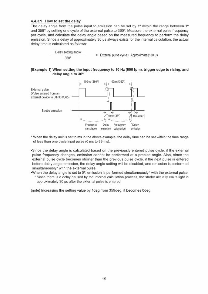
4.4.3.1 How to set the delayThe delay angle from the pulse input to emission can be set by 1º within the range between 1º and 359º by setting one cycle of the external pulse to 360º. Measure the external pulse frequency per cycle, and calculate the delay angle based on the measured frequency to perform the delay emission.Sinceadelayofapproximately30μsalwaysexistsfortheinternalcalculation,theactualdelay time is calculated as follows:
Delay setting angle× External pulse cycle + Approximately 30 μs
360°
[Example 1] When setting the input frequency to 10 Hz (600 fpm), trigger edge to rising, and delay angle to 36º
Ex ter nal p ul se( Pul se enter ed f r om an ex ter nal dev ice to D T - 3 6 1 / 3 6 5 )
S tr ob e emission
1 0 0 ms(3 6 0 º)
1 0 ms(3 6 º)
F r eq uencycal cul ation
D el ayemission
F r eq uencycal cul ation
1 0 0 ms(3 6 0 º)
1 0 ms(3 6 º)
D el ayemission
* When the delay unit is set to ms in the above example, the delay time can be set within the time range of less than one cycle input pulse (0 ms to 99 ms).
•Sincethedelayangleiscalculatedbasedonthepreviouslyenteredpulsecycle,iftheexternalpulse frequency changes, emission cannot be performed at a precise angle. Also, since the external pulse cycle becomes shorter than the previous pulse cycle, if the next pulse is entered before delay angle emission, the delay angle setting will be disabled, and emission is performed simultaneously* with the external pulse.•Whenthedelayangleissetto0º,emissionisperformedsimultaneously* with the external pulse.
* Since there is a delay caused by the internal calculation process, the strobe actually emits light in approximately30μsaftertheexternalpulseisentered.
(note) Increasing the setting value by 1deg from 359deg, it becomes 0deg.
20
4.5 Memory functionEach setting value can be saved and read out.
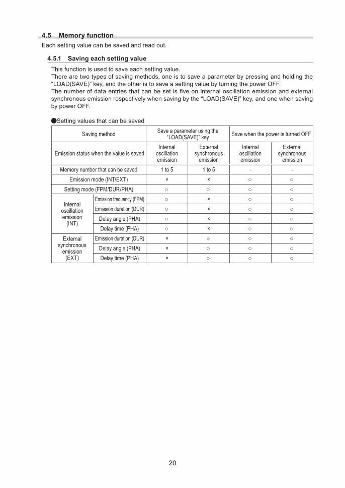
4.5.1 Saving each setting valueThis function is used to save each setting value.There are two types of saving methods, one is to save a parameter by pressing and holding the “LOAD(SAVE)” key, and the other is to save a setting value by turning the power OFF.Thenumberofdataentriesthatcanbeset isfiveon internaloscillationemissionandexternalsynchronous emission respectively when saving by the “LOAD(SAVE)” key, and one when saving by power OFF.
Setting values that can be saved
Saving method Save a parameter using the “LOAD(SAVE)” key Save when the power is turned OFF
Emission status when the value is savedInternal
oscillation emission
External synchronous
emission
Internal oscillation emission
External synchronous
emissionMemory number that can be saved 1 to 5 1 to 5 - -
Emission mode (INT/EXT) × × ○ ○Setting mode (FPM/DUR/PHA) ○ ○ ○ ○
Internal oscillation emission
(INT)
Emission frequency (FPM) ○ × ○ ○Emission duration (DUR) ○ × ○ ○
Delay angle (PHA) ○ × ○ ○Delay time (PHA) ○ × ○ ○
External synchronous
emission(EXT)
Emission duration (DUR) × ○ ○ ○Delay angle (PHA) × ○ ○ ○Delay time (PHA) × ○ ○ ○
21
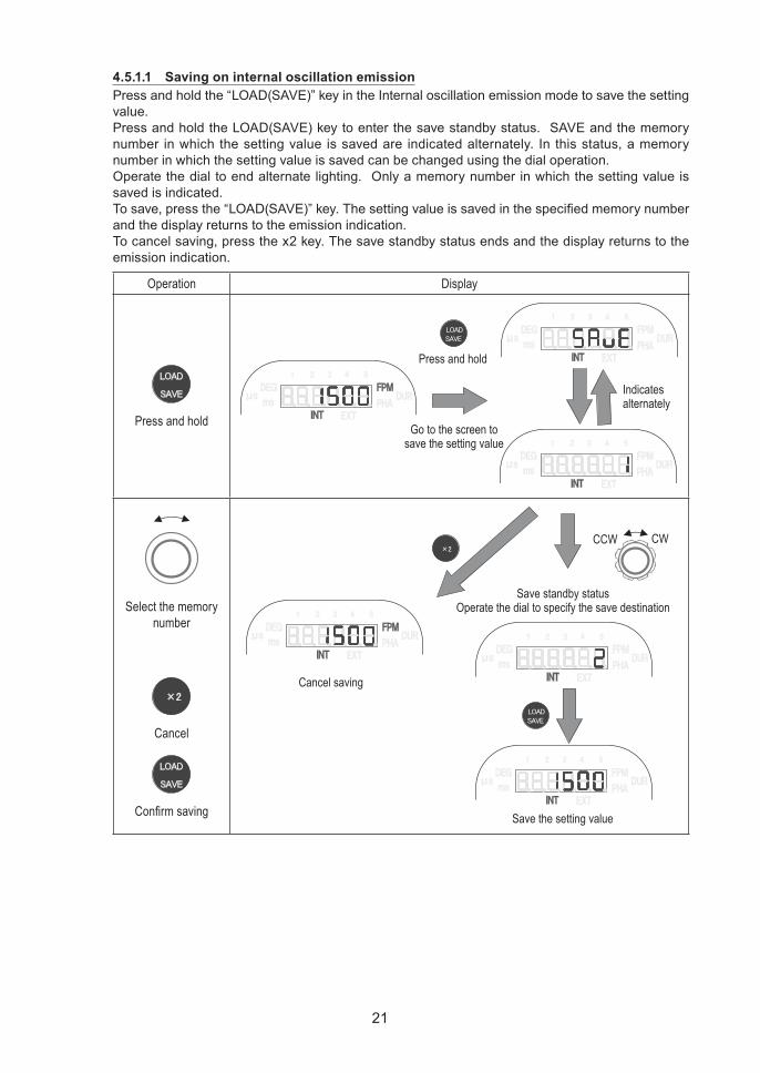
4.5.1.1 Saving on internal oscillation emissionPress and hold the “LOAD(SAVE)” key in the Internal oscillation emission mode to save the setting value.Press and hold the LOAD(SAVE) key to enter the save standby status. SAVE and the memory number in which the setting value is saved are indicated alternately. In this status, a memory number in which the setting value is saved can be changed using the dial operation.Operate the dial to end alternate lighting. Only a memory number in which the setting value is saved is indicated.Tosave,pressthe“LOAD(SAVE)”key.Thesettingvalueissavedinthespecifiedmemorynumberand the display returns to the emission indication.To cancel saving, press the x2 key. The save standby status ends and the display returns to the emission indication.
Operation D isplay
Press and hold
I ndicatesal ter natel y
Pr ess and hol d
G o to the scr een tosav e the setting v al ue
Select the memory number
C ancel
Confirm saving S av e the setting v al ue
S av e standb y statusO p er ate the dial to sp ecif y the sav e destination
C ancel sav ing
C C W C W
22
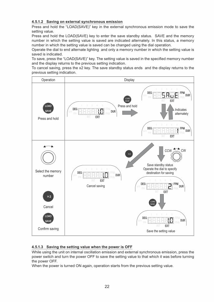
4.5.1.2 Saving on external synchronous emissionPress and hold the “LOAD(SAVE)” key in the external synchronous emission mode to save the setting value.Press and hold the LOAD(SAVE) key to enter the save standby status. SAVE and the memory number in which the setting value is saved are indicated alternately. In this status, a memory number in which the setting value is saved can be changed using the dial operation.Operate the dial to end alternate lighting and only a memory number in which the setting value is saved is indicated.Tosave,pressthe“LOAD(SAVE)”key.Thesettingvalueissavedinthespecifiedmemorynumberand the display returns to the previous setting indication.To cancel saving, press the x2 key. The save standby status ends and the display returns to the previous setting indication.
Operation D isplay
Press and hold
Pr ess and hol dI ndicatesal ter natel y
Select the memory number
C ancel
Confirm saving S av e the setting v al ue
S av e standb y statusO p er ate the dial to sp ecif y
destination f or sav ing
C ancel sav ing
C C W C W
4.5.1.3 Saving the setting value when the power is OFFWhile using the unit on internal oscillation emission and external synchronous emission, press the power switch and turn the power OFF to save the setting value to that which it was before turning the power OFF.When the power is turned ON again, operation starts from the previous setting value.
23
4.5.2 Reading out each setting valueThis function is used to read out each setting value.
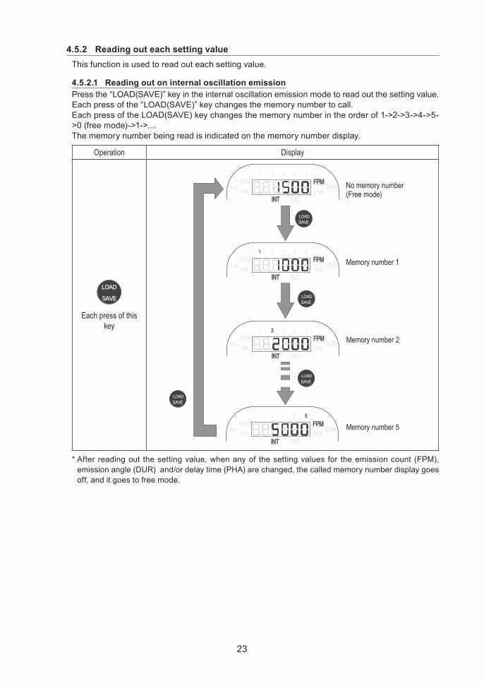
4.5.2.1 Reading out on internal oscillation emissionPress the “LOAD(SAVE)” key in the internal oscillation emission mode to read out the setting value.Each press of the “LOAD(SAVE)” key changes the memory number to call.Each press of the LOAD(SAVE) key changes the memory number in the order of 1->2->3->4->5->0 (free mode)->1->....The memory number being read is indicated on the memory number display.
Operation D isplay
Each press of this key
N o memor y numb er( F r ee mode)
M emor y numb er 1
M emor y numb er 2
M emor y numb er 5
* After reading out the setting value, when any of the setting values for the emission count (FPM), emission angle (DUR) and/or delay time (PHA) are changed, the called memory number display goes off, and it goes to free mode.
24
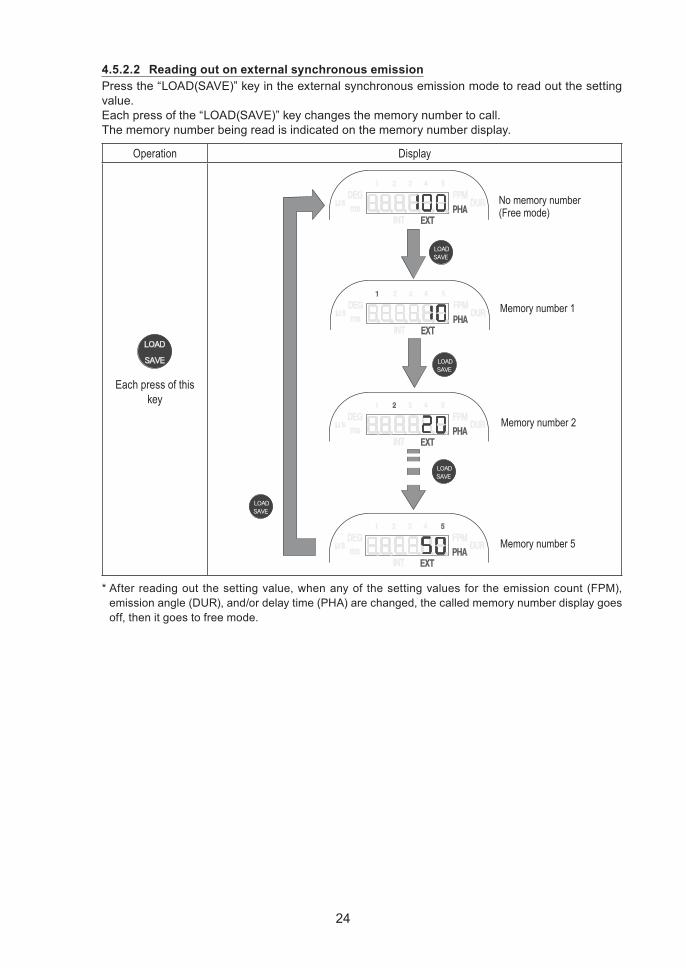
4.5.2.2 Reading out on external synchronous emissionPress the “LOAD(SAVE)” key in the external synchronous emission mode to read out the setting value.Each press of the “LOAD(SAVE)” key changes the memory number to call.The memory number being read is indicated on the memory number display.
Operation D isplay
Each press of this key
N o memor y numb er( F r ee mode)
M emor y numb er 1
M emor y numb er 2
M emor y numb er 5
* After reading out the setting value, when any of the setting values for the emission count (FPM), emission angle (DUR), and/or delay time (PHA) are changed, the called memory number display goes off, then it goes to free mode.
25
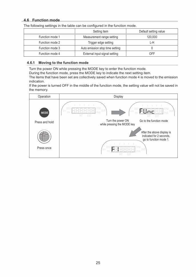
4.6 Function modeThefollowingsettingsinthetablecanbeconfiguredinthefunctionmode.
Setting item Default setting valueFunction mode 1 Measurement range setting 120,000Function mode 2 Trigger edge setting L - HFunction mode 3 Auto emission stop time setting 0Function mode 4 External input signal setting OFF
4.6.1 Moving to the function modeTurn the power ON while pressing the MODE key to enter the function mode.During the function mode, press the MODE key to indicate the next setting item.The items that have been set are collectively saved when function mode 4 is moved to the emission indication.If the power is turned OFF in the middle of the function mode, the setting value will not be saved in the memory.
Operation D isplay
Press and hold
Press once
T ur n the p ow er O Nw hil e p r essing the M O D E k ey
G o to the f unction mode
A f ter the ab ov e disp l ay isindicated f or 2 seconds,g o to f unction mode 1 .
26
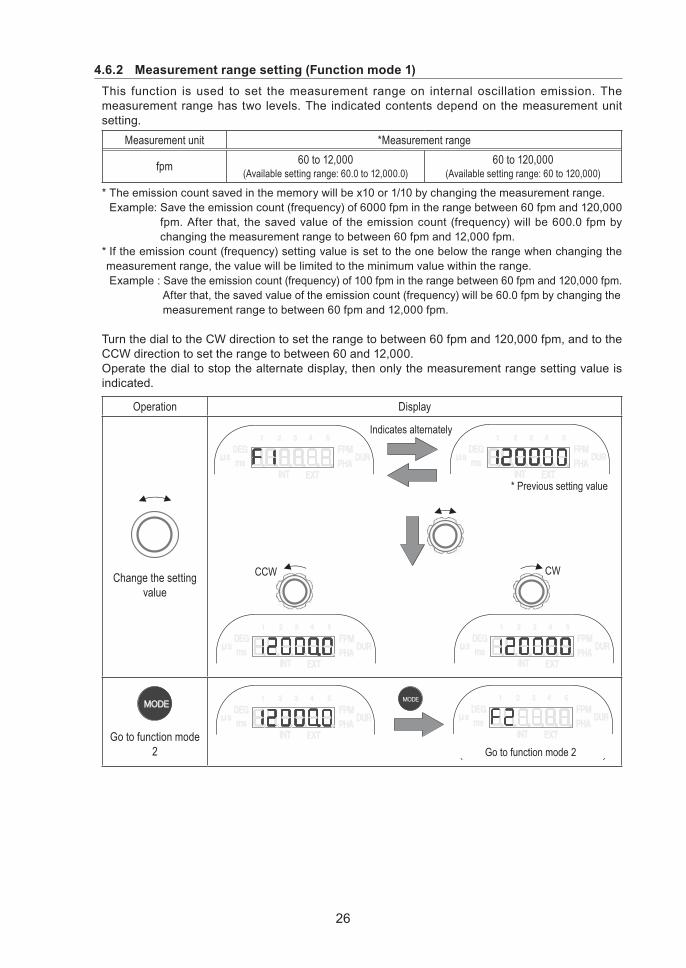
4.6.2 Measurement range setting (Function mode 1)This function is used to set the measurement range on internal oscillation emission. The measurement range has two levels. The indicated contents depend on the measurement unit setting.
Measurement unit *Measurement range
fpm 60 to 12,000(Available setting range: 60.0 to 12,000.0)
60 to 120,000(Available setting range: 60 to 120,000)
* The emission count saved in the memory will be x10 or 1/10 by changing the measurement range.Example: Save the emission count (frequency) of 6000 fpm in the range between 60 fpm and 120,000
fpm. After that, the saved value of the emission count (frequency) will be 600.0 fpm by changing the measurement range to between 60 fpm and 12,000 fpm.
* If the emission count (frequency) setting value is set to the one below the range when changing the measurement range, the value will be limited to the minimum value within the range. Example : Save the emission count (frequency) of 100 fpm in the range between 60 fpm and 120,000 fpm. After that, the saved value of the emission count (frequency) will be 60.0 fpm by changing the measurement range to between 60 fpm and 12,000 fpm.
Turn the dial to the CW direction to set the range to between 60 fpm and 120,000 fpm, and to the CCW direction to set the range to between 60 and 12,000.Operate the dial to stop the alternate display, then only the measurement range setting value is indicated.
Operation D isplay
Change the setting value
I ndicates al ter natel y
* Pr ev ious setting v al ue
C C W C W
Go to function mode 2 G o to f unction mode 2
27
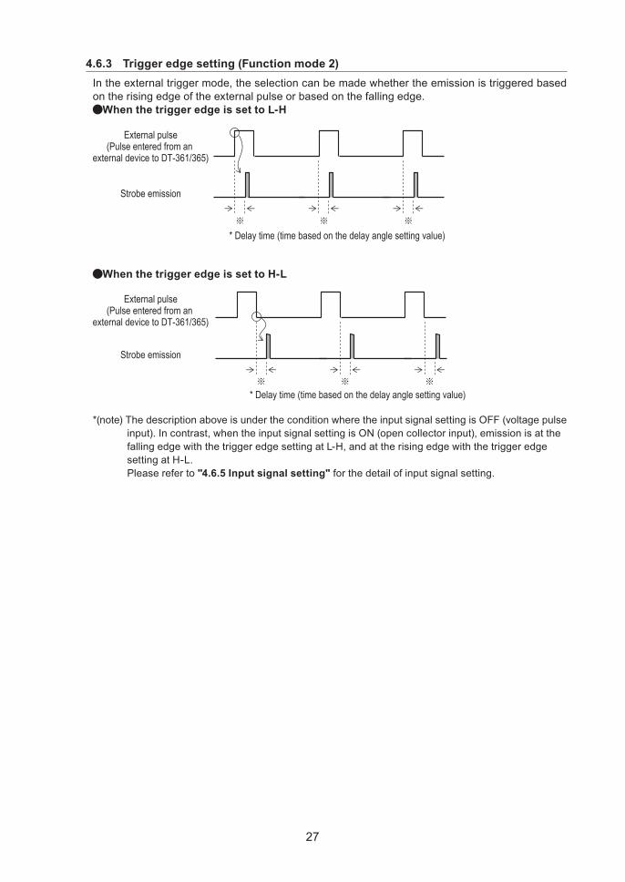
4.6.3 Trigger edge setting (Function mode 2)In the external trigger mode, the selection can be made whether the emission is triggered based on the rising edge of the external pulse or based on the falling edge.
When the trigger edge is set to L-H
Ex ter nal p ul se( Pul se enter ed f r om an
ex ter nal dev ice to D T - 3 6 1 / 3 6 5 )
S tr ob e emission
* D el ay time ( time b ased on the del ay ang l e setting v al ue)※ ※ ※
When the trigger edge is set to H-L
S tr ob e emission
* D el ay time ( time b ased on the del ay ang l e setting v al ue)※ ※ ※
Ex ter nal p ul se( Pul se enter ed f r om an
ex ter nal dev ice to D T - 3 6 1 / 3 6 5 )
*(note) The description above is under the condition where the input signal setting is OFF (voltage pulse input). In contrast, when the input signal setting is ON (open collector input), emission is at the falling edge with the trigger edge setting at L-H, and at the rising edge with the trigger edge setting at H-L. Please refer to "4.6.5 Input signal setting" for the detail of input signal setting.

28
Turn the dial to the CW direction to set the trigger edge to H-L.Turn the dial to the CCW direction to set the trigger edge to L-H.Operate the dial to stop the alternate display and only the trigger edge setting value is indicated.
Operation D isplay
Change the setting value
Indicates alternately
* P rev ious setting v alue
C C W C W
Go to function mode 3 G o to f unction mode 3
29
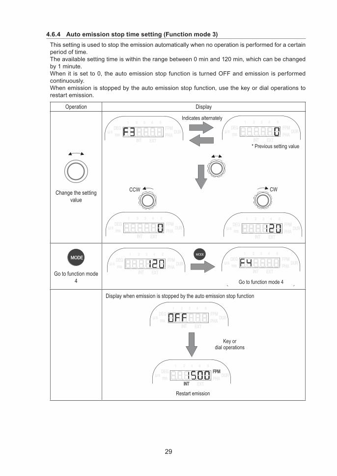
4.6.4 Auto emission stop time setting (Function mode 3)This setting is used to stop the emission automatically when no operation is performed for a certain period of time.The available setting time is within the range between 0 min and 120 min, which can be changed by 1 minute.When it is set to 0, the auto emission stop function is turned OFF and emission is performed continuously.When emission is stopped by the auto emission stop function, use the key or dial operations to restart emission.
Operation D isplay
Change the setting value
I ndicates al ter natel y
* Pr ev ious setting v al ue
C C W C W
Go to function mode 4 G o to f unction mode 4
Display when emission is stopped by the auto emission stop function
R estar t emission
K ey ordial op er ations
30
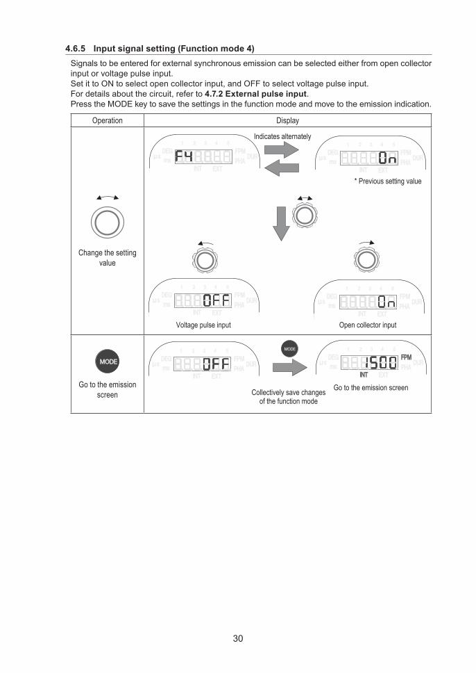
4.6.5 Input signal setting (Function mode 4)Signals to be entered for external synchronous emission can be selected either from open collector input or voltage pulse input.Set it to ON to select open collector input, and OFF to select voltage pulse input.For details about the circuit, refer to 4.7.2 External pulse input.Press the MODE key to save the settings in the function mode and move to the emission indication.
Operation D isplay
Change the setting value
I ndicates al ter natel y
* Pr ev ious setting v al ue
O p en col l ector inp utV ol tag e p ul se inp ut
Go to the emission screen
G o to the emission scr eenC ol l ectiv el y sav e chang esof the f unction mode
31
4.7 External I/O connector4.7.1
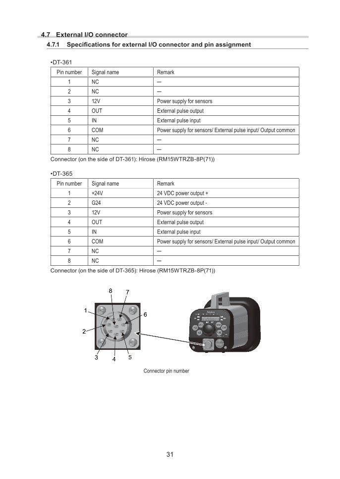
•DT-361Pin number Signal name Remark
1 NC ─2 NC ─3 12V Power supply for sensors4 OUT External pulse output5 IN External pulse input6 COM Power supply for sensors/ External pulse input/ Output common7 NC ─8 NC ─
Connector (on the side of DT-361): Hirose (RM15WTRZB-8P(71))
•DT-365Pin number Signal name Remark
1 +24V 24 VDC power output +2 G24 24 VDC power output -3 12V Power supply for sensors4 OUT External pulse output5 IN External pulse input6 COM Power supply for sensors/ External pulse input/ Output common7 NC ─8 NC ─
Connector (on the side of DT-365): Hirose (RM15WTRZB-8P(71))
Connector pin number
32
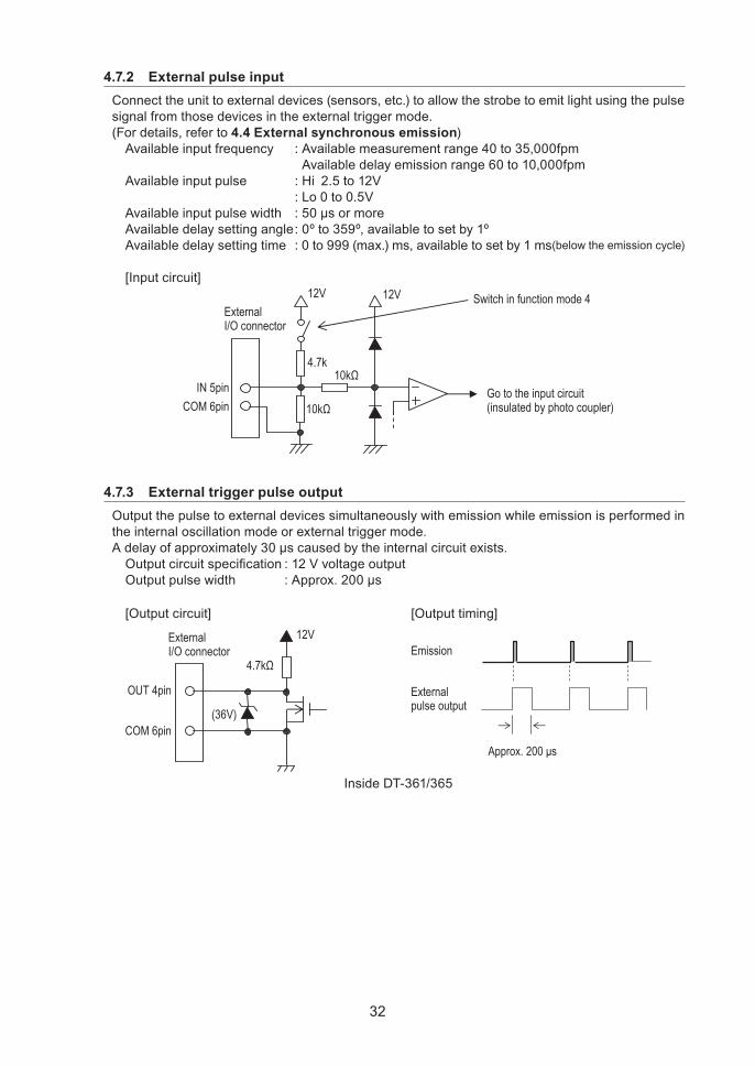
4.7.2 External pulse inputConnect the unit to external devices (sensors, etc.) to allow the strobe to emit light using the pulse signal from those devices in the external trigger mode.(For details, refer to 4.4 External synchronous emission)
Available input frequency : Available measurement range 40 to 35,000fpmAvailable delay emission range 60 to 10,000fpm
Available input pulse : Hi 2.5 to 12V : Lo 0 to 0.5VAvailableinputpulsewidth :50μsormoreAvailable delay setting angle : 0º to 359º, available to set by 1ºAvailable delay setting time : 0 to 999 (max.) ms, available to set by 1 ms(below the emission cycle)
[Input circuit]
ExternalI/ O connector
IN 5 pinC OM 6 pin
1 2 V
G o to the input circuit( insulated by photo coupler)
10k4 .7 k
10k
1 2 V S witch in function mode 4
4.7.3 External trigger pulse outputOutput the pulse to external devices simultaneously with emission while emission is performed in the internal oscillation mode or external trigger mode.Adelayofapproximately30μscausedbytheinternalcircuitexists.Outputcircuitspecification:12VvoltageoutputOutputpulsewidth :Approx.200μs
[Output circuit] [Output timing]
( 3 6 V )
ExternalI/ O connector
OU T 4 pin
C OM 6 pin
1 2 V
4.7k Emission
Ex ter nalp ul se outp ut
Approx. 200 μs
Inside DT-361/365
33
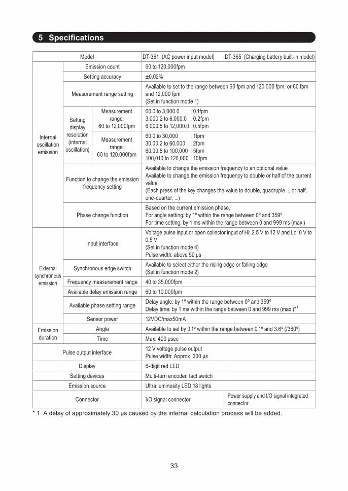
5 Specifications
M odel DT-361 (AC power input model) D T- 3 6 5 ( Charging battery built-in model)
Internal oscillation emission
Emission count 60 to 120,000fpmSetting accuracy ±0.02%
Measurement range settingAvailable to set to the range between 60 fpm and 120,000 fpm, or 60 fpm and 12,000 fpm(Set in function mode 1)
Setting display
resolution (internal
oscillation)
Measurement range:
60 to 12,000fpm
60.0 to 3,000.0 : 0.1fpm3,000.2 to 6,000.0 : 0.2fpm6,000.5 to 12,000.0 : 0.5fpm
Measurement range:
60 to 120,000fpm
60.0 to 30,000 : 1fpm30,00.2 to 60,000 : 2fpm60,00.5 to 100,000 : 5fpm100,010 to 120,000 : 10fpm
Function to change the emission frequency setting
Available to change the emission frequency to an optional valueAvailable to change the emission frequency to double or half of the current value(Each press of the key changes the value to double, quadruple..., or half, one-quarter, ...)
Phase change functionBased on the current emission phase,For angle setting: by 1º within the range between 0º and 359ºFor time setting: by 1 ms within the range between 0 and 999 ms (max.)
Externalsynchronous
emission
Input interface
Voltage pulse input or open collector input of Hi: 2.5 V to 12 V and Lo: 0 V to 0.5 V(Set in function mode 4)Pulse width: above 50 μs
Synchronous edge switch Available to select either the rising edge or falling edge(Set in function mode 2)
Frequency measurement range 40 to 35,000fpmAvailable delay emission range 60 to 10,000fpm
Available phase setting range Delay angle: by 1º within the range between 0º and 359ºDelay time: by 1 ms within the range between 0 and 999 ms (max.)*1
Sensor power 12VDC/max50mA
Emission duration
Angle Available to set by 0.1º within the range between 0.1º and 3.6º (/360º)Time Max. 400 μsec
Pulse output interface 12 V voltage pulse outputPulse width: Approx. 200 μs
D isplay 6-digit red LEDSetting devices Multi-turn encoder, tact switchEmission source Ultra luminosity LED 18 lights
Connector I/O signal connector Power supply and I/O signal integrated connector
*1Adelayofapproximately30μscausedbytheinternalcalculationprocesswillbeadded.
34
Memory function •Saving the setting value when the power is OFF• Saving 5 setting values each on internal oscillation and external synchronous emission respectively
Auto emission stop Available to set continuous emission, or set the time to stop emission by 1 minute within the range between 1 min and 120 min.(Set in function mode 3)
Power 100 to 230VAC(50Hz/60Hz)
Built-in NiMH battery•Continuous emission timeApprox. 2 hours (when the emission duration is set to 3.6º)Approx. 5 hours (when the emission duration is set to 1.0º)
•Charging time: Approx. 2.5 hours
Supplied AC adapter•Input : 100 to 240VAC•Output : 24VDC
Operating temperature 32 to 104 °F (0 to 40 ºC)Operating environment No dust and/or corrosive gasesCompliance standard RoHSProtection structure Equivalent to IP65 NEMA 4X
Weight Approx. 4 lb (1.8 kg) Approx. 4.6 lb (2.1 kg)
Standard accessories External I/O connector (8 pin) RM15WTPZA-8S(71) x 1 Dedicated AC adapter x 1
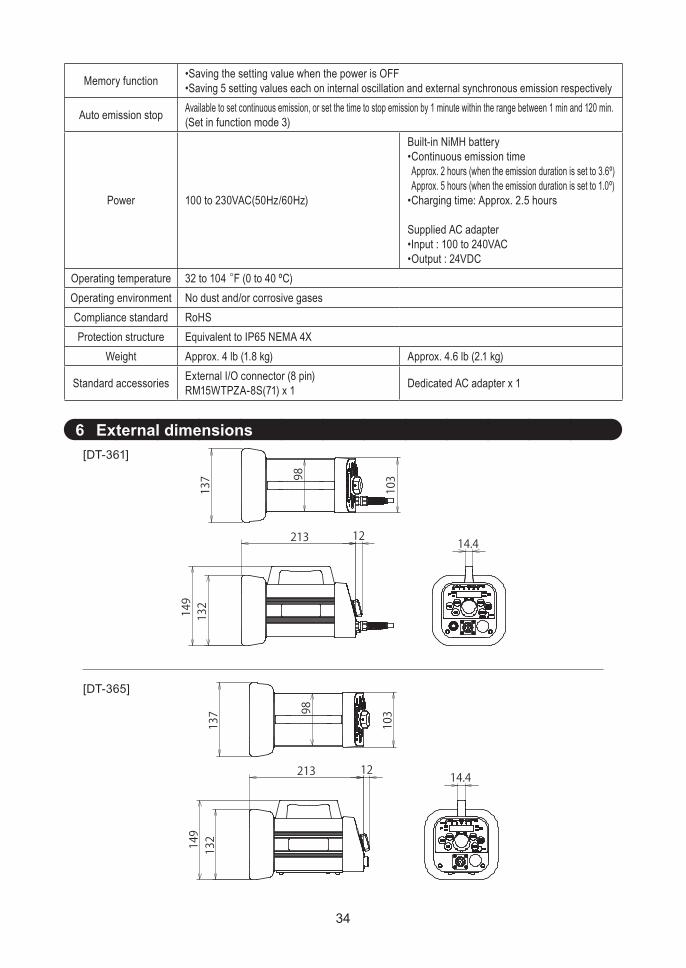
6 External dimensions[DT-361]
[DT-365]
137
149
213 1214.4
132
98
103
137
213 1214.4
149
132
98
103
35
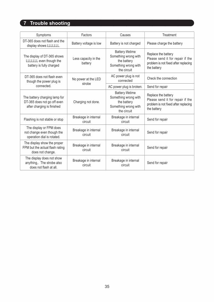
7 Trouble shooting
Symptoms Factors Causes TreatmentDT-365 does not flash and the
display shows LLLLLLL. Battery voltage is low Battery is not charged Please charge the battery
The display of D T- 3 6 5 shows LLLLLLL even though the
battery is fully charged
L ess capacity in the battery
Battery lifetimeSomething wrong with
the batterySomething wrong with
the circuit
Replace the batteryPlease send it for repair if the problem is not fixed after replacing the battery
DT-365 does not flash even though the power plug is
connected.
No power at the LED strobe
AC power plug is not connected Check the connection
AC power plug is broken. Send for repair
The battery charging lamp for DT-365 does not go off even
after charging is finishedCharging not done.
Battery lifetimeSomething wrong with
the batterySomething wrong with
the circuit
Replace the batteryPlease send it for repair if the problem is not fixed after replacing the battery
Flashing is not stable or stop Breakage in internal circuit
Breakage in internal circuit Send for repair
The display or FPM does not change even though the
operation dial is rotated.
Breakage in internal circuit
Breakage in internal circuit Send for repair
The display show the proper FPM but the actual flash rating
does not change.
Breakage in internal circuit
Breakage in internal circuit Send for repair
The display does not show anything,. The strobe also
does not flash at all.
Breakage in internal circuit
Breakage in internal circuit Send for repair