Embed Size (px)
Citation preview
HB2010, Morschach, 2010.09.27~10.01
High Intensity Aspects of
the CSNS Accelerators
J.Y. Tang, S.N. Fu, L. Ma
Institute of High Energy Physics, CAS
Page HB2010, Morschach, Sep. 27-Oct. 1, J.Y. Tang 2
Main topics
• Introduction to CSNS project
• Space charge effects in CSNS accelerators
– Linac
– LRBT
– RCS
• Beam loss and collimation
– Beam loss control in linac
– Halo collimation in LRBT
– Beam loss and collimation in RCS
• Beam spot uniformization at the target
• Other high intensity aspects
• Conclusions
Page HB2010, Morschach, Sep. 27-Oct. 1, J.Y. Tang 3
Introduction to CSNS Project
Page HB2010, Morschach, Sep. 27-Oct. 1, J.Y. Tang 4
Page HB2010, Morschach, Sep. 27-Oct. 1, J.Y. Tang 5
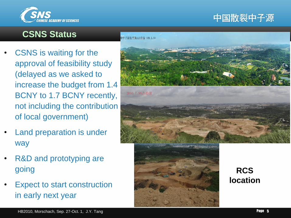
CSNS Status
• CSNS is waiting for the
approval of feasibility study
(delayed as we asked to
increase the budget from 1.4
BCNY to 1.7 BCNY recently,
not including the contribution
of local government)
• Land preparation is under
way
• R&D and prototyping are
going
• Expect to start construction
in early next year
RCS
location
Page HB2010, Morschach, Sep. 27-Oct. 1, J.Y. Tang 6
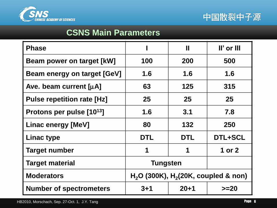
CSNS Main Parameters
Phase I II II’ or III
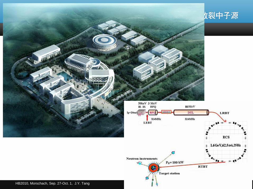
Beam power on target [kW] 100 200 500
Beam energy on target [GeV] 1.6 1.6 1.6
Ave. beam current [mA] 63 125 315
Pulse repetition rate [Hz] 25 25 25
Protons per pulse [1013] 1.6 3.1 7.8
Linac energy [MeV] 80 132 250
Linac type DTL DTL DTL+SCL
Target number 1 1 1 or 2
Target material Tungsten
Moderators H2O (300K), H2(20K, coupled & non)
Number of spectrometers 3+1 20+1 >=20
Page HB2010, Morschach, Sep. 27-Oct. 1, J.Y. Tang 7
Space charge effects in CSNS accelerators
Page HB2010, Morschach, Sep. 27-Oct. 1, J.Y. Tang 8
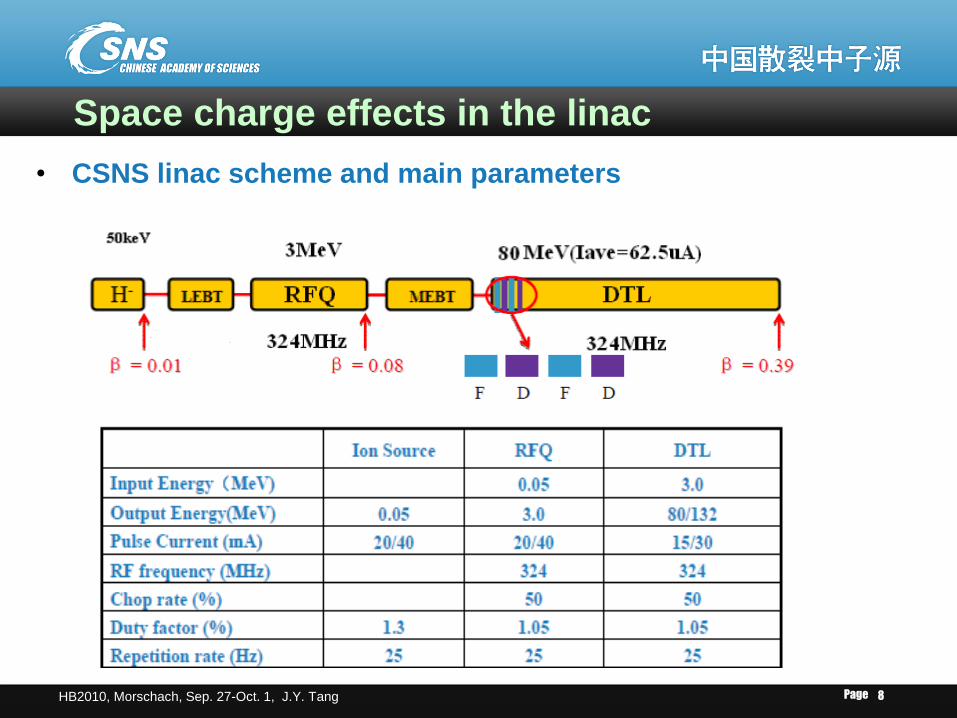
Space charge effects in the linac
• CSNS linac scheme and main parameters
Page HB2010, Morschach, Sep. 27-Oct. 1, J.Y. Tang 9
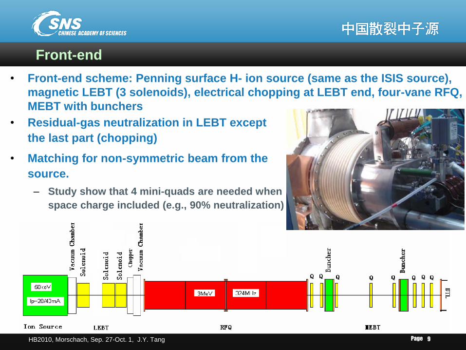
Front-end
• Front-end scheme: Penning surface H- ion source (same as the ISIS source),
magnetic LEBT (3 solenoids), electrical chopping at LEBT end, four-vane RFQ,
MEBT with bunchers
• Residual-gas neutralization in LEBT except
the last part (chopping)
• Matching for non-symmetric beam from the
source.
– Study show that 4 mini-quads are needed when
space charge included (e.g., 90% neutralization)
Page HB2010, Morschach, Sep. 27-Oct. 1, J.Y. Tang 10
• The RFQ is designed by following the success of ADS-RFQ
(four-vane, 3.5 MeV, 352MHz, 7% duty factor)
– It can accelerate high intensity beam until 50 mA with good
transmission efficiency (~93%).
• MEBT has been shortened by taking away the choppers
– Shorter is better by following the comments of ATAC review
– Critical section for emittance growth due to the space charge
effects.
– Non-adiabatic change of the focusing structure
– Adjustability for different beam intensity
Page HB2010, Morschach, Sep. 27-Oct. 1, J.Y. Tang 11
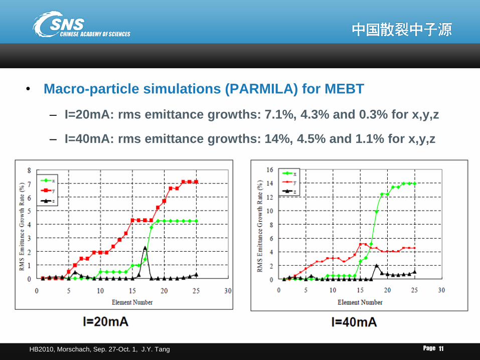
• Macro-particle simulations (PARMILA) for MEBT
– I=20mA: rms emittance growths: 7.1%, 4.3% and 0.3% for x,y,z
– I=40mA: rms emittance growths: 14%, 4.5% and 1.1% for x,y,z
Page HB2010, Morschach, Sep. 27-Oct. 1, J.Y. Tang 12
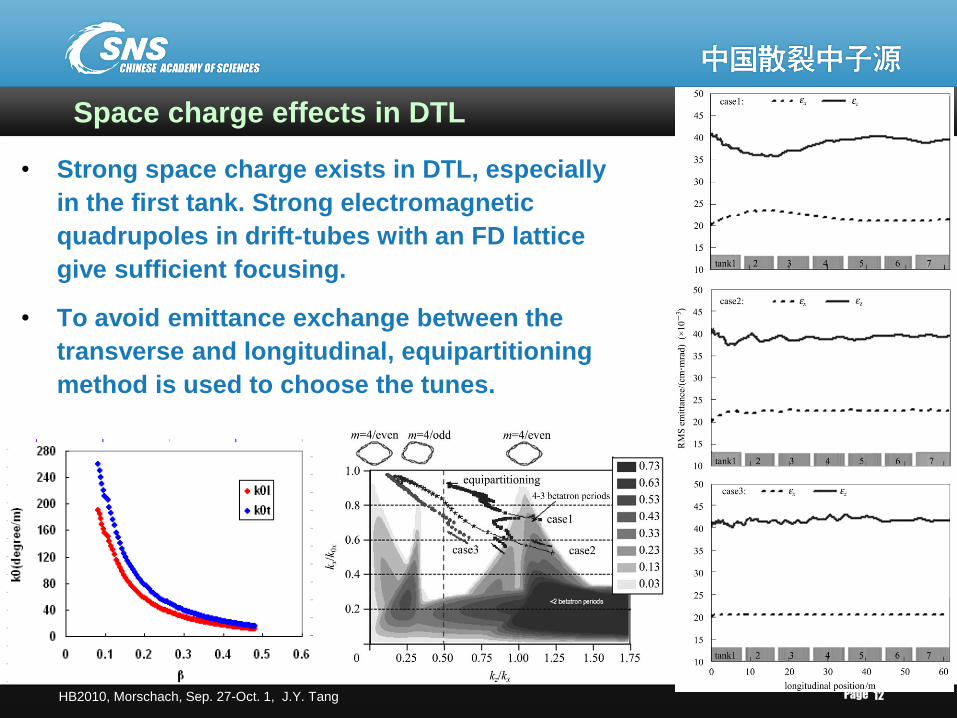
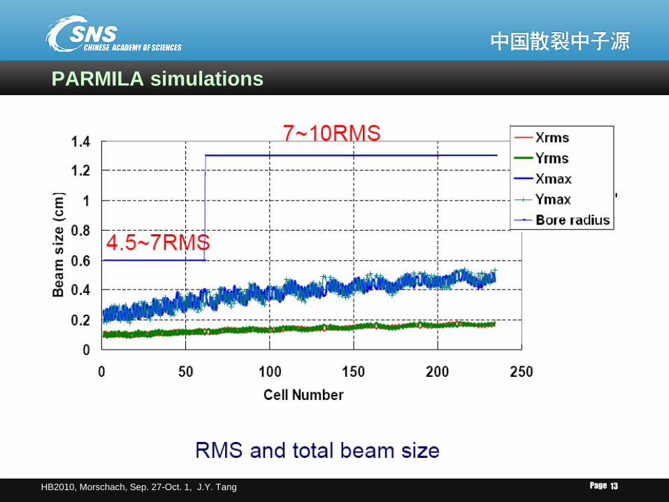
Space charge effects in DTL
• Strong space charge exists in DTL, especially
in the first tank. Strong electromagnetic
quadrupoles in drift-tubes with an FD lattice
give sufficient focusing.
• To avoid emittance exchange between the
transverse and longitudinal, equipartitioning
method is used to choose the tunes.
Page HB2010, Morschach, Sep. 27-Oct. 1, J.Y. Tang 13
PARMILA simulations
Page HB2010, Morschach, Sep. 27-Oct. 1, J.Y. Tang 14
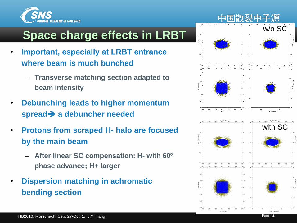
Space charge effects in LRBT
• Important, especially at LRBT entrance
where beam is much bunched
– Transverse matching section adapted to
beam intensity
• Debunching leads to higher momentum
spread a debuncher needed
• Protons from scraped H- halo are focused
by the main beam
– After linear SC compensation: H- with 60
phase advance; H+ larger
• Dispersion matching in achromatic
bending section
w/o SC
with SC
Page HB2010, Morschach, Sep. 27-Oct. 1, J.Y. Tang 15
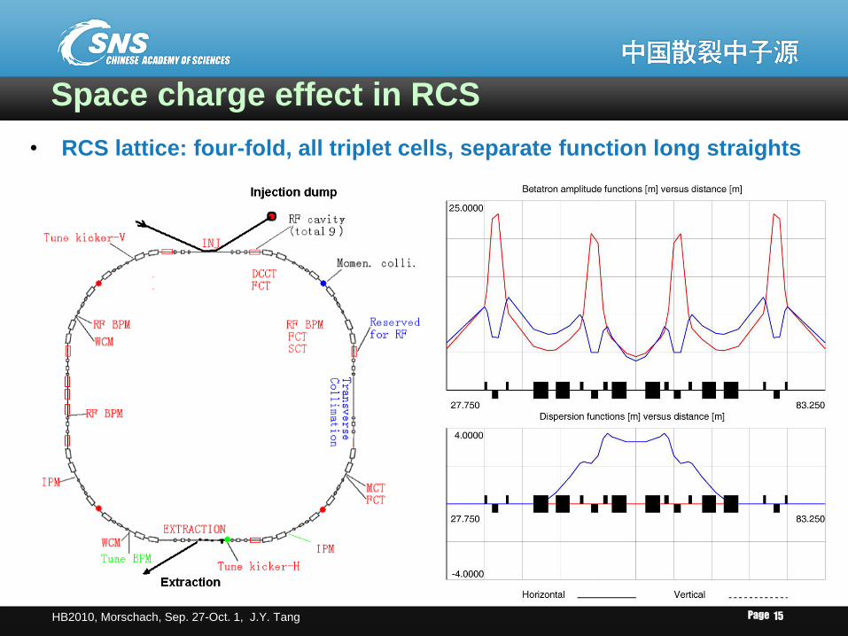
Space charge effect in RCS
• RCS lattice: four-fold, all triplet cells, separate function long straights
Page HB2010, Morschach, Sep. 27-Oct. 1, J.Y. Tang 16
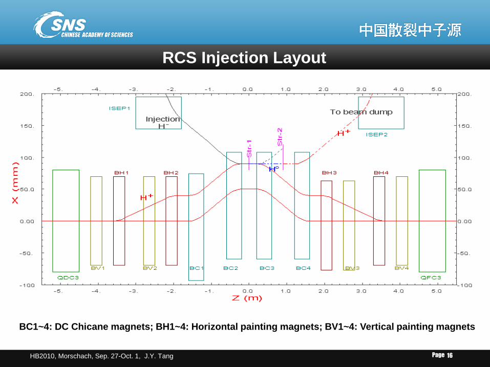
RCS Injection Layout
BC1~4: DC Chicane magnets; BH1~4: Horizontal painting magnets; BV1~4: Vertical painting magnets
Page HB2010, Morschach, Sep. 27-Oct. 1, J.Y. Tang 17
3D simulations of space charge effects in RCS
• Injection (transverse)
– Using 3D ORBIT simulations including space charge
– Focusing on: distribution uniformity, emittance blowup and foil
traversal
– Different working points
– Correlated and anti-correlated painting schemes
– Linac peak current dependence
• Injection (longitudinal)
– Chopping rate dependence
– Longitudinal painting (only with momentum offset)
• RF capture and initial acceleration
– RF voltage curve dependence
– Trade-off between transverse and longitudinal beam losses
S. Wang’s talk
(WE01A03)
Page HB2010, Morschach, Sep. 27-Oct. 1, J.Y. Tang 18
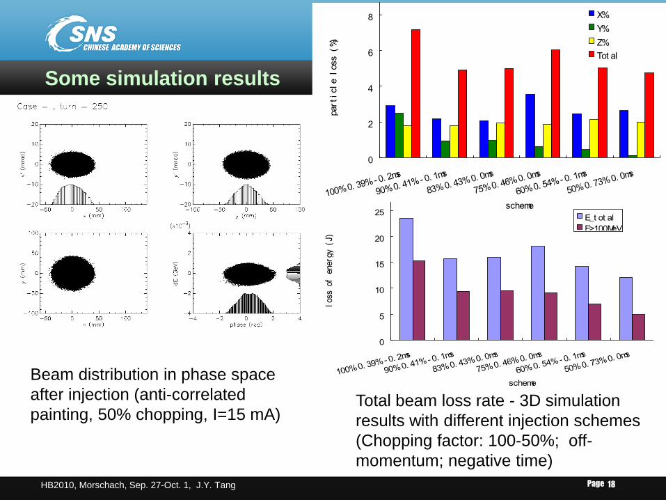
Anti-correlated painting
Beam distribution in phase space
after injection (anti-correlated
painting, 50% chopping, I=15 mA) Total beam loss rate - 3D simulation
results with different injection schemes
(Chopping factor: 100-50%; off-
momentum; negative time)
0
2
4
6
8
100% 0. 39% - 0. 2ms
90% 0. 41% - 0. 1ms
83% 0. 43% 0. 0ms
75% 0. 46% 0. 0ms
60% 0. 54% - 0. 1ms
50% 0. 73% 0. 0ms
scheme
particle loss (%)
X%
Y%
Z%
Tot al
Some simulation results
0
5
10
15
20
25
100% 0. 39% - 0. 2ms
90% 0. 41% - 0. 1ms
83% 0. 43% 0. 0ms
75% 0. 46% 0. 0ms
60% 0. 54% - 0. 1ms
50% 0. 73% 0. 0ms
scheme
loss
of
ener
gy (
J)
E_t ot al
E>100MeV
Page HB2010, Morschach, Sep. 27-Oct. 1, J.Y. Tang 19
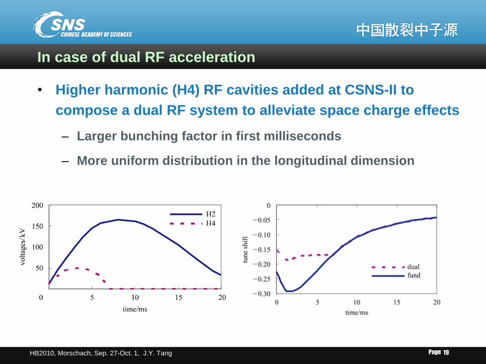
In case of dual RF acceleration
• Higher harmonic (H4) RF cavities added at CSNS-II to
compose a dual RF system to alleviate space charge effects
– Larger bunching factor in first milliseconds
– More uniform distribution in the longitudinal dimension
Page HB2010, Morschach, Sep. 27-Oct. 1, J.Y. Tang 20
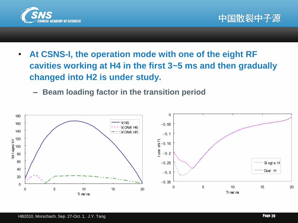
• At CSNS-I, the operation mode with one of the eight RF
cavities working at H4 in the first 3~5 ms and then gradually
changed into H2 is under study.
– Beam loading factor in the transition period
0
20
40
60
80
100
120
140
160
180
0 5 10 15 20
Ti me/ ms
Voltages/kV
V( H2)
V( CAV8 H4)
V( CAV8 H2)
- 0. 35
- 0. 3
- 0. 25
- 0. 2
- 0. 15
- 0. 1
- 0. 05
0
0 5 10 15 20
Ti me/ ms
tune shift
Si ngl e H
Dual H
Page HB2010, Morschach, Sep. 27-Oct. 1, J.Y. Tang 21
Beam Losses and Collimations
Page HB2010, Morschach, Sep. 27-Oct. 1, J.Y. Tang 22
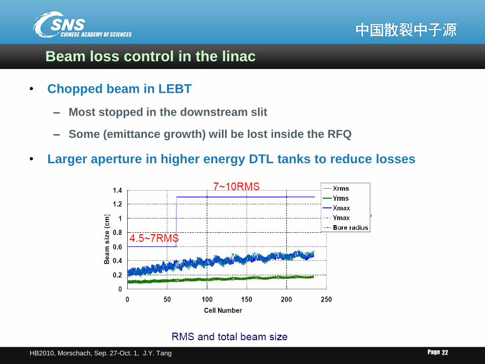
Beam loss control in the linac
• Chopped beam in LEBT
– Most stopped in the downstream slit
– Some (emittance growth) will be lost inside the RFQ
• Larger aperture in higher energy DTL tanks to reduce losses
Page HB2010, Morschach, Sep. 27-Oct. 1, J.Y. Tang 23
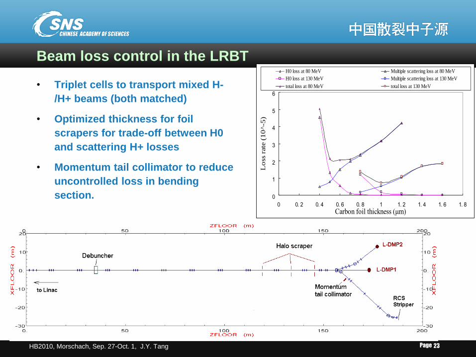
Beam loss control in the LRBT
• Triplet cells to transport mixed H-
/H+ beams (both matched)
• Optimized thickness for foil
scrapers for trade-off between H0
and scattering H+ losses
• Momentum tail collimator to reduce
uncontrolled loss in bending
section. 0
1
2
3
4
5
6
0 0. 2 0. 4 0. 6 0. 8 1 1. 2 1. 4 1. 6 1. 8
Carbon foil thickness (μm)
Lo
ss r
ate
(1
0^-5
)
H0 loss at 80 MeV Multiple scattering loss at 80 MeV
H0 loss at 130 MeV Multiple scattering loss at 130 MeV
total loss at 80 MeV total loss at 130 MeV
Page HB2010, Morschach, Sep. 27-Oct. 1, J.Y. Tang 24
Beam loss and collimation in RCS
• Beam loss mechanisms
– Nuclear scattering and multiple scattering
– Non-stripped H- particles
– RF capture loss
– Transverse emittance growth due to space charge and non-linear
resonance crossing
– Loss at the extraction septum due to misfiring of the kickers
– Accidental total beam loss
• Collimation of lost particles
– Most happen at low energy or close to injection energy lower loss
power and higher collimation efficiency
– Total loss rate (<1kW): <5%at CSNS-I, <2% at CSNS-II, <1% at CSNS-III
– Uncontrolled beam loss rate: <1W/m
• Collimation method
– Two-stage collimation for both transverse and momentum halos
Page HB2010, Morschach, Sep. 27-Oct. 1, J.Y. Tang 25
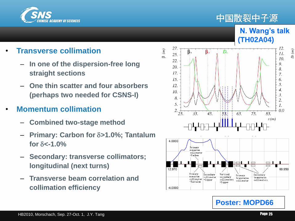
• Transverse collimation
– In one of the dispersion-free long
straight sections
– One thin scatter and four absorbers
(perhaps two needed for CSNS-I)
• Momentum collimation
– Combined two-stage method
– Primary: Carbon for >1.0%; Tantalum
for <-1.0%
– Secondary: transverse collimators;
longitudinal (next turns)
– Transverse beam correlation and
collimation efficiency
N. Wang’s talk
(TH02A04)
Poster: MOPD66
Page HB2010, Morschach, Sep. 27-Oct. 1, J.Y. Tang 26
Beam Spot Uniformization at Target and Others
Page HB2010, Morschach, Sep. 27-Oct. 1, J.Y. Tang 27
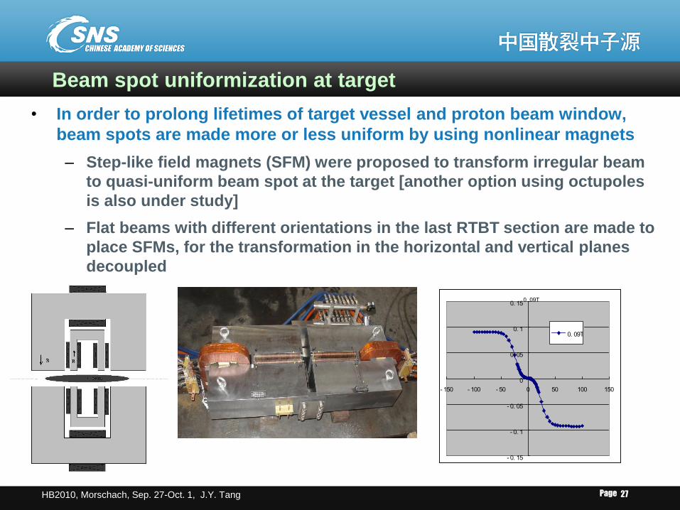
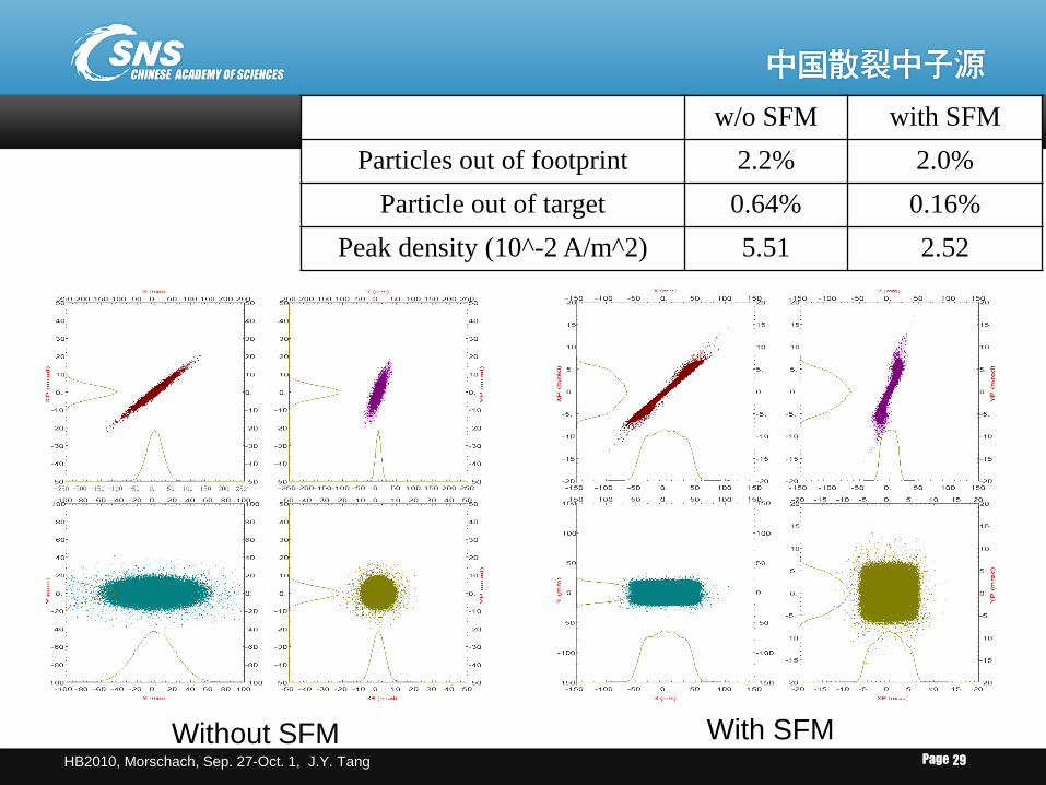
Beam spot uniformization at target
• In order to prolong lifetimes of target vessel and proton beam window,
beam spots are made more or less uniform by using nonlinear magnets
– Step-like field magnets (SFM) were proposed to transform irregular beam
to quasi-uniform beam spot at the target [another option using octupoles
is also under study]
– Flat beams with different orientations in the last RTBT section are made to
place SFMs, for the transformation in the horizontal and vertical planes
decoupled
0. 09T
- 0. 15
- 0. 1
- 0. 05
0
0. 05
0. 1
0. 15
- 150 - 100 - 50 0 50 100 150
0. 09T
Page HB2010, Morschach, Sep. 27-Oct. 1, J.Y. Tang 28
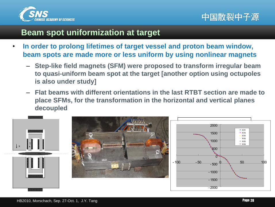
Beam spot uniformization at target
• In order to prolong lifetimes of target vessel and proton beam window,
beam spots are made more or less uniform by using nonlinear magnets
– Step-like field magnets (SFM) were proposed to transform irregular beam
to quasi-uniform beam spot at the target [another option using octupoles
is also under study]
– Flat beams with different orientations in the last RTBT section are made to
place SFMs, for the transformation in the horizontal and vertical planes
decoupled
0. 09T
- 0. 15
- 0. 1
- 0. 05
0
0. 05
0. 1
0. 15
- 150 - 100 - 50 0 50 100 150
0. 09T
- 2000
- 1500
- 1000
- 500
0
500
1000
1500
2000
- 100 - 50 0 50 100
系列1
系列2
系列3
系列4
系列5
系列6
Page HB2010, Morschach, Sep. 27-Oct. 1, J.Y. Tang 29
Without SFM With SFM
w/o SFM with SFM
Particles out of footprint 2.2% 2.0%
Particle out of target 0.64% 0.16%
Peak density (10^-2 A/m^2) 5.51 2.52
Page HB2010, Morschach, Sep. 27-Oct. 1, J.Y. Tang 3
0
Other high intensity aspects in CSNS
• Beam loading effect
– Injection can be with non-chopped beam or chopped beam
– With non-chopped injection, RF voltage starts from very low to
obtain quasi-adiabatic RF capture. Beam loading effect is very
important and more sophisticated LLRF with feed-forward is
needed.
– At CSNS upgrading, even with chopped beam injection, beam
loading is also very important due to higher circulating current.
• Lifetime of stripping foil
– Lifetime of the main stripping foil becomes a serious concern at
CSNS-III. First temperature estimate shows similar to the SNS/AR
one at 1.4 MW.
– CSNS uses relatively thicker and larger foil to reduce H-/H0
particles
Page HB2010, Morschach, Sep. 27-Oct. 1, J.Y. Tang 31
Conclusions
• Following the experience of ISIS, SNS and J-PARC, the high
intensity beam at CSNS is considered to be manageable
• Space charge effects play important roles in both the linac
and the RCS, even in the beam transport line LRBT. They
are key in limiting the accumulated particles.
• Uncontrolled beam loss rate is taken to be 1W/m,
sophisticated collimations are taken to localize most of lost
particles in the whole CSNS accelerator.
• Major factors in limiting the power increase in the CSNS
upgrading have been considered.
Page HB2010, Morschach, Sep. 27-Oct. 1, J.Y. Tang 32


![uei2]t - Gujarat State Portal NP...hli-01J"'n~b1n1~ 19~ Pltl1"'1't lJ-'(11-t 1(.)1.% 'J.Y~.I'kf·l](https://img.pdfslide.us/doc/110x75/5ec8e49805c7c527ca5889c8/uei2t-gujarat-state-portal-np-hli-01jnb1n1-19-pltl11t-lj-11-t.jpg)