Embed Size (px)
Citation preview
ELECTRONICS, VOL. 15, NO. 1, JUNE 2011 11
Abstract—Electrostatic precipitators (ESP) or electrofilters
remove flying ashes and fine particles from the flue gas in thermal
power plants, before passing the gas into the chimney. Maximum
allowable value of dust is 50 mg/m3 and it requires that the
efficiency of the ESPs better than 99%, which calls for an
increase of active surface of the electrodes, hence increasing the
filter volume and the weight of steel used for the filter. In
previous decades, electrostatic precipitators in thermal power
plants were fed by thyristor controlled, single-phase fed devices
having a high degree of reliability, but with a relatively low
collection efficiency, hence requiring large effective surface of the
collection plates and a large weight of steel construction in order
to achieve the prescribed emission limits. Collection efficiency and
energy efficiency of the electrostatic precipitator can be increased
by applying high frequency high voltage power supply (HF HV).
Electrical engineering faculty of the University of Belgrade (ETF)
has developed technology and HF HV equipment for the ESP
power supply. This solution was subjected to extensive
experimental investigation at TE Morava from 2008. to 2010.
High frequency power supply is proven to reduce emission two
times in controlled conditions while increasing energy efficiency
of the precipitator, compared to the conventional thyristor
controlled 50 Hz supply. Two high frequency high voltage unit
AR70/1000 with parameters 70 kV and 1000 mA are installed at
TE Morava and thoroughly testes. It was found that the HF HV
power supply of the ESP at TE Morava increases collection
efficiency so that emission of fine particles and flying ashes are
halved, brought down to only 50% of the emissions encountered
with conventional 50 Hz thyristor driven power supplies. On the
basis of this study, conclusion is drawn that the equipment
comprising HF HV supplies are the best solution for new ESP
installations, as well as for the reconstruction of existing facilities.
The paper describes the topology of the HF HV power supply,
power management and controls, and brings the most important
details of the implementation. It is found that the HF HV solution
achieves several significant improvements over the conventional
thyristor system. It is possible to provide more precise control of
the ESP parameters such as the output voltages and currents. It is
also possible to make a rapid increase or decrease in voltage and
to effectuate a very fast response to load changes. Due to this
advantages it is possible to suppress the supply quickly in the case
of sparking, reducing the spark energy and the quantity of
ionized gasses produced by the electric arc. Reduction in the
spark energy is up to 10 times compared to conventional
thyristors solution. This means that the erosion of the electrode
system is significantly reduced, and that the quality of the
collection plates is preserved for much longer periods. At the
same time, lower quantity of ionized gasses produced by the spark
contribute to much shorter de-ionization intervals, required to
S. Vukosavić is with the University of Belgrade, School of Electrical
Engineering (e-mail: [email protected]).
quit sparking and evacuate charged particles in order to reinstate
the voltage and proceed with the operation. In addition, HF HV
power supply provides a significant reduction in size and weight
of the complete ESP installation, hence reducing the tons of steel
that has to be built in. Therefore, the HF HV power supply may
be the key instrument to reducing the cost of the de-dusting
ecological equipment. Besides, size and weight reduction leads to
cost savings of installation and maintenance. According to
estimates, savings in steel may reach 30%, contributing to the
overall cost savings of roughly 20%. Within this paper, in
addition to describing the AR70/1000 unit topology and principles
of operation, the paper presents the results and measurements
obtained during extensive experimental investigations wherein
performances of 50 Hz based thyristor units with T/R sets are
compared to HF HV power supply.
Index Terms—Electrostatic precipitator, High-voltage high-
frequency supply.
I. INTRODUCTION
LTHOUGH many readers are already acquainted with the
functioning of the ESP, this introduction provides a brief
reminder for those who have not come across this topic. ESP
are used for removal of ultrafine dust particles from flue gas.
The most frequent use is the removal of tiny particles of flying
ashes in thermal power plants. In order to achieve this, it is
necessary for the flue gas to move in the horizontal direction
through a strong electric field established between sets of
large, parallel electrode plates. The distance between the plates
ranges from 300 mm to 500 mm. The plates extend vertically
and along the gas flow. The positively charged electrodes are
grounded, while the negative ones are connected to the DC
voltage source ranging from 50 kV to 100 kV. The negatively
charged electrodes have a number of spikes or small diameter
wire, which contributes to corona and creates large amount of
ions. The current density due to the corona discharge reaches
1 mA/m2 and it affects a great deal the precipitation and dust
collection. Dust particles are being charged by means of
diffusion and the field effect and they move towards positively
charged electrode, where they are collected. Therefore, the
negative electrode is also called the emission plate, while the
positive, grounded electrode is also called the colleting plate.
Particle migration speed towards the collecting plate is one of
most significant parameters of electrofilters. The collecting
electrodes are periodically shaken off, i.e. rapped. The rapping
process is performed by means of the spinning hammers which
High Frequency Power Supply for Electrostatic
Precipitators in Thermal Power Plants
Slobodan Vukosavić
A
ELECTRONICS, VOL. 15, NO. 1, JUNE 2011 12
periodically knock on the electrode supports and cause
mechanical vibration which helps detaching the dust layer
deposits from the plates. The ash being removed during
rapping falls into the V-shaped hoppers, located below the
ESP chamber. From there, the dust and ashes are transported
further by means of water or pressurized air. For the sake of an
efficient dust removal, each ESP has at least three series
connected sections. The flue gas enters the ESP through the
entry section, and then passes through one or more middle
sections. Upon leaving these sections, the flue gas passes
through the exit section. By passing through the sequence of
the serially connected sections the precipitation efficiency (i.e.
filtering efficiency) reaches 99.9%. With this efficiency and
with every cubic meter of gas leaving the boiler and entering
the ESP with 50 g of flying ashes, the gas leaving the
electrofilter and entering into the chimney may have the total
of 50 mg of dust per every cubic meter of gas. In order to
create the electric field and the corona discharge current, the
electrodes should be connected with a controllable DC voltage
source which provides voltages from 50 kV to 100 kV.
Considering the fact that sparks often occur between the
electrodes and the electric arc occasionally appears, the source
is exposed to periodic short circuit conditions. In the event of
arcing, it is necessary to switch off the power supply for an
interval of time so as to allow for recombination or removal of
charged particles created by the arc. Premature voltage rise
will find residues of conductive, ionized gas between the
plates, re-entering hence the short circuit condition. After re-
establishing of the dielectric strength of the gas, the voltage
between the plates may be increased and the precipitation
process may continue. The required DC current depends on the
surface of the plates. It is necessary to provide the current of 1
mA for every square meter of the electrode surface. Hence, an
electrofilter with 10000 m2 requires the current of 10 А. The
ESP power supply and controls are traditionally based on one
pair of antiparall thyristors which alter the amplitude of the
primary AC voltage. The primary supply is usually single-
phase, 400 V 50 Hz. By changing the firing angle, the voltage
is being changed in the range from 0 to 400 V and brought to
the primary of the line frequency power transformer whose
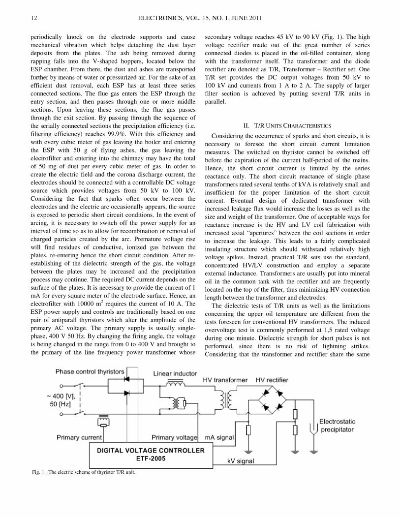
secondary voltage reaches 45 kV to 90 kV (Fig. 1). The high
voltage rectifier made out of the great number of series
connected diodes is placed in the oil-filled container, along
with the transformer itself. The transformer and the diode
rectifier are denoted as T/R, Transformer – Rectifier set. One
T/R set provides the DC output voltages from 50 kV to
100 kV and currents from 1 А to 2 А. The supply of larger
filter section is achieved by putting several T/R units in
parallel.
II. T/R UNITS CHARACTERISTICS
Considering the occurrence of sparks and short circuits, it is
necessary to foresee the short circuit current limitation
measures. The switched on thyristor cannot be switched off
before the expiration of the current half-period of the mains.
Hence, the short circuit current is limited by the series
reactance only. The short circuit reactance of single phase
transformers rated several tenths of kVА is relatively small and
insufficient for the proper limitation of the short circuit
current. Eventual design of dedicated transformer with
increased leakage flux would increase the losses as well as the
size and weight of the transformer. One of acceptable ways for
reactance increase is the HV and LV coil fabrication with
increased axial “apertures” between the coil sections in order
to increase the leakage. This leads to a fairly complicated
insulating structure which should withstand relatively high
voltage spikes. Instead, practical T/R sets use the standard,
concentrated HV/LV construction and employ a separate
external inductance. Transformers are usually put into mineral
oil in the common tank with the rectifier and are frequently
located on the top of the filter, thus minimizing HV connection
length between the transformer and electrodes.
The dielectric tests of T/R units as well as the limitations
concerning the upper oil temperature are different from the
tests foreseen for conventional HV transformers. The induced
overvoltage test is commonly performed at 1,5 rated voltage
during one minute. Dielectric strength for short pulses is not
performed, since there is no risk of lightning strikes.
Considering that the transformer and rectifier share the same
Fig. 1. The electric scheme of thyristor T/R unit.
ELECTRONICS, VOL. 15, NO. 1, JUNE 2011 13
container (housing) and the same oil, it is necessary to ensure
that the increase in the upper oil temperature does not exceed
the values that can damage the rectifier. Hence, the ESP
transformer losses should be measured with a great care.
Among other things, a salient feature of the transformer is the
capability to resist frequent short circuits which occur due to
sparking between the electrons. Hence, one part of these
transformers testing is the repetitive occurrence of short
circuits with the analysis of thermal and mechanical
robustness.
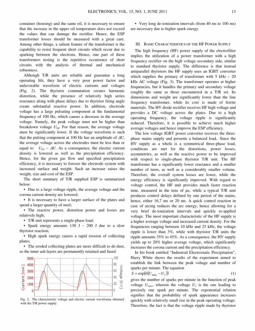
Although T/R units are reliable and guarantee a long
operating life, they have a very poor power factor and
unfavorable waveform of electric currents and voltages
(Fig. 2). The thyristor commutation creates harmonic
distortion, while the presence of relatively high series
reactance along with phase delays due to thyristor firing angle
create substantial reactive power. In addition, electrode
voltage has a large pulsating component at the fundamental
frequency of 100 Hz, which causes a decrease in the average
voltage. Namely, the peak voltage must not be higher than
breakdown voltage Ubd. For that reason, the average voltage
must be significantly lower. If the voltage waveform is such
that the pulsing component at 100 Hz has an amplitude of ∆U,
the average voltage across the electrodes must be less than or
equal to Ubd − ∆U. As a consequence, the electric current
density is lowered as well as the precipitation efficiency.
Hence, for the given gas flow and specified precipitation
efficiency, it is necessary to foresee the electrode system with
increased surface and weight. Such an increase raises the
weight, size and cost of the ESP.
The short summary of T/R supplied ESP is summarized
below:
• Due to a large voltage ripple, the average voltage and the
corona current density are lowered;
• It is necessary to have a larger surface of the plates and
spend a larger quantity of steel;
• The reactive power, distortion power and losses are
relatively high;
• T/R unit represents a single-phase load;
• Spark energy amounts 130 Ј – 200 Ј due to a slow
thyristor reaction;
• High spark energy causes a rapid erosion of collecting
plates;
• The eroded collecting plates are more difficult to de-dust,
so the inner ash layers are permanently retained and fused
• Very long de-ionization intervals (from 40 ms to 100 ms)
are necessary due to higher spark energy.
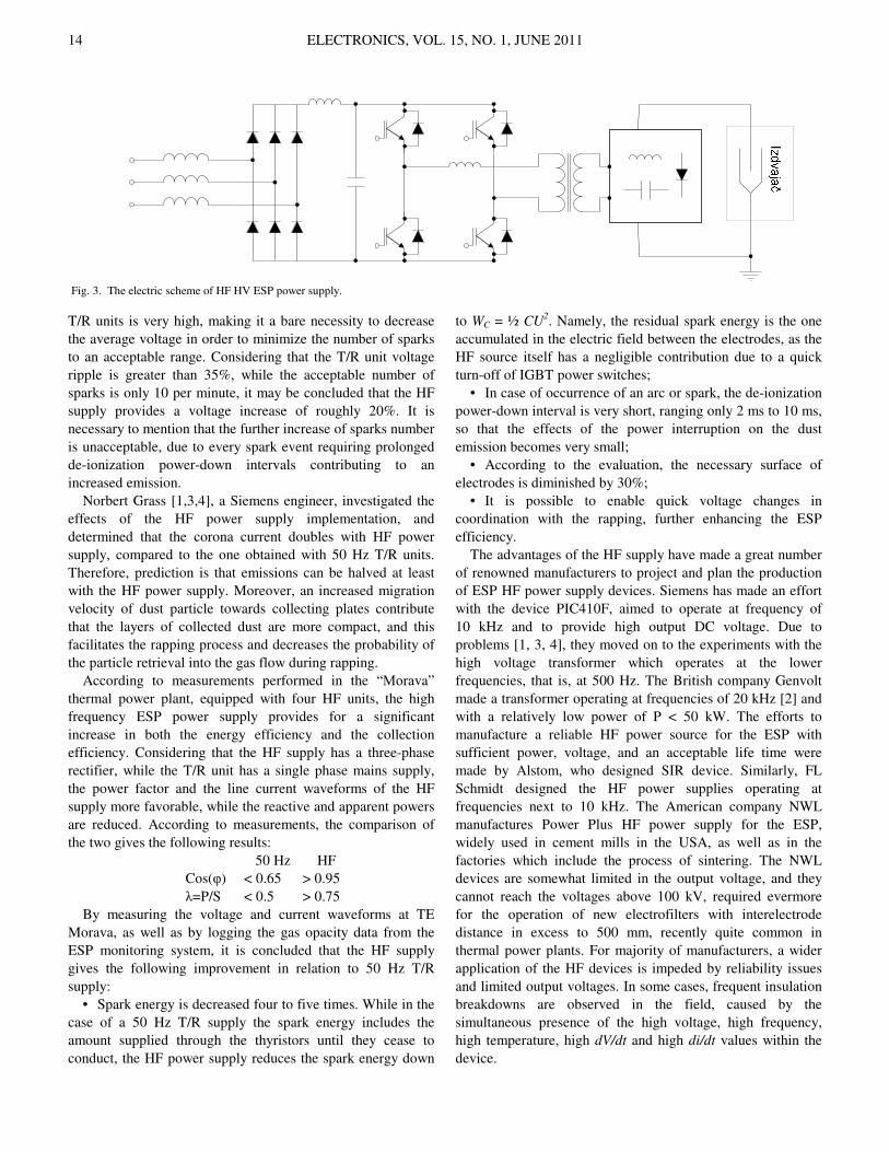
III. BASIC CHARACTERISTICS OF THE HF POWER SUPPLY
The high frequency (HF) power supply of the electrofilter
implies the utilization of a power transformer with a high
frequency rectifier on the high voltage secondary side, similar
to standard thyristor supply. The difference is that instead
antiparallel thyristors the HF supply uses an IGBT converter
which supplies the primary of transformer with 5 kHz – 20
kHz AC voltage (Fig. 3). The transformer operates at higher
frequencies, but it handles the primary and secondary voltage
roughly the same as those encountered in a T/R set. Its
dimensions and weight are significantly lower than the line
frequency transformer, while its core is made of ferrite
materials. The HV diode rectifier receives HF high voltage and
provides a DC voltage across the plates. Due to a high
operating frequency, the voltage ripple is significantly
reduced. Therefore, it is possible to achieve much higher
average voltages and hence improve the ESP efficiency.
The low voltage IGBT power converter receives the three-
phase mains supply and presents a balanced load.. Since the
HV supply as a whole is a symmetrical three-phase load,
conditions are met for the distortions, power losses,
asymmetries, as well as the reactive power to be improved
with respect to single-phase thyristor T/R unit. The HF
transformer has a significantly lower reactance and a smaller
number of turns, as well as a considerably smaller volume.
Therefore, the overall system losses are lower, while the
energy efficiency is significantly improved. With regard to
voltage control, the HF unit provides much faster reaction
time, measured in the tens of µs, while a typical T/R unit
produces control delays defined by one period of the mains,
hence, either 16,7 ms or 20 ms. A quick control reaction in
case of arcing reduces the arc energy, hence allowing for a
very brief de-ionization intervals and quickly re-applied
voltage. The most important characteristic of the HF supply is
a higher average voltage and increased current density. For the
frequencies ranging between 10 kHz and 25 kHz, the voltage
ripple is lower than 3%, while with thyristor T/R units the
ripple amounts 35% to 45%. As a consequence, the HV supply
yields up to 20% higher average voltage, which significantly
increases the corona current and the precipitation efficiency.
In his book entitled “Industrial Electrostatic Precipitation”,
Harry White shows the results of the experiment aimed to
establish the link between the peak voltage and number of
sparks per minute. The equation
( )( )1maxexp UUbS −= (1)
gives the number of sparks per minute in the function of peak
voltage Umax, wherein the voltage U1 is the one leading to
precisely one spark per minute. The exponential relation
signifies that the probability of spark appearance increases
quickly with relatively small rise in the peak operating voltage.
Therefore, the fact is that the voltage ripple made by thyristor
Fig. 2. The characteristic voltage and electric current waveforma obtained
with the T/R power supply.
ELECTRONICS, VOL. 15, NO. 1, JUNE 2011 14
T/R units is very high, making it a bare necessity to decrease
the average voltage in order to minimize the number of sparks
to an acceptable range. Considering that the T/R unit voltage
ripple is greater than 35%, while the acceptable number of
sparks is only 10 per minute, it may be concluded that the HF
supply provides a voltage increase of roughly 20%. It is
necessary to mention that the further increase of sparks number
is unacceptable, due to every spark event requiring prolonged
de-ionization power-down intervals contributing to an
increased emission.
Norbert Grass [1,3,4], a Siemens engineer, investigated the
effects of the HF power supply implementation, and
determined that the corona current doubles with HF power
supply, compared to the one obtained with 50 Hz T/R units.
Therefore, prediction is that emissions can be halved at least
with the HF power supply. Moreover, an increased migration
velocity of dust particle towards collecting plates contribute
that the layers of collected dust are more compact, and this
facilitates the rapping process and decreases the probability of
the particle retrieval into the gas flow during rapping.
According to measurements performed in the “Моrаva”
thermal power plant, equipped with four HF units, the high
frequency ESP power supply provides for a significant
increase in both the energy efficiency and the collection
efficiency. Considering that the HF supply has a three-phase
rectifier, while the T/R unit has a single phase mains supply,
the power factor and the line current waveforms of the HF
supply more favorable, while the reactive and apparent powers
are reduced. According to measurements, the comparison of
the two gives the following results:
50 Hz HF
Cos(φ) < 0.65 > 0.95
λ=P/S < 0.5 > 0.75
By measuring the voltage and current waveforms at TE
Morava, as well as by logging the gas opacity data from the
ESP monitoring system, it is concluded that the HF supply
gives the following improvement in relation to 50 Hz T/R
supply:
• Spark energy is decreased four to five times. While in the
case of a 50 Hz T/R supply the spark energy includes the
amount supplied through the thyristors until they cease to
conduct, the HF power supply reduces the spark energy down
to WC = ½ CU2. Namely, the residual spark energy is the one
accumulated in the electric field between the electrodes, as the
HF source itself has a negligible contribution due to a quick
turn-off of IGBT power switches;
• In case of occurrence of an arc or spark, the de-ionization
power-down interval is very short, ranging only 2 ms to 10 ms,
so that the effects of the power interruption on the dust
emission becomes very small;
• According to the evaluation, the necessary surface of
electrodes is diminished by 30%;
• It is possible to enable quick voltage changes in
coordination with the rapping, further enhancing the ESP
efficiency.
The advantages of the HF supply have made a great number
of renowned manufacturers to project and plan the production
of ESP HF power supply devices. Siemens has made an effort
with the device PIC410F, aimed to operate at frequency of
10 kHz and to provide high output DC voltage. Due to
problems [1, 3, 4], they moved on to the experiments with the
high voltage transformer which operates at the lower
frequencies, that is, at 500 Hz. The British company Genvolt
made a transformer operating at frequencies of 20 kHz [2] and
with a relatively low power of P < 50 kW. The efforts to
manufacture a reliable HF power source for the ESP with
sufficient power, voltage, and an acceptable life time were
made by Alstom, who designed SIR device. Similarly, FL
Schmidt designed the HF power supplies operating at
frequencies next to 10 kHz. The American company NWL
manufactures Power Plus HF power supply for the ESP,
widely used in cement mills in the USA, as well as in the
factories which include the process of sintering. The NWL
devices are somewhat limited in the output voltage, and they
cannot reach the voltages above 100 kV, required evermore
for the operation of new electrofilters with interelectrode
distance in excess to 500 mm, recently quite common in
thermal power plants. For majority of manufacturers, a wider
application of the HF devices is impeded by reliability issues
and limited output voltages. In some cases, frequent insulation
breakdowns are observed in the field, caused by the
simultaneous presence of the high voltage, high frequency,
high temperature, high dV/dt and high di/dt values within the
device.
Fig. 3. The electric scheme of HF HV ESP power supply.
ELECTRONICS, VOL. 15, NO. 1, JUNE 2011 15
IV. THE PROBLEMS OF THE EXISTING HF SOLUTIONS
The problems encountered in the HF electrofilter supply
exploitation are frequently reflected in (i) the breakdown of
semiconductor power switches in the primary circuit, (ii)
secondary circuit insulation breakdown or (iii) the problems of
EM noise and control. The first problem emerges due to the
circumstance that the IGBT power switches deliver next to
100 kW while commutating at the frequencies from 10 kHz to
25 kHz. Hence, the IGBT power switches operate at the limit
of their performance. Therefore, unless zero current switching
(ZCS) or the zero voltage switching (ZVS) is ensured, they
may suffer serious overheating. The second problem is caused
by the rapid insulation degradation and aging in the presence
of high dV/dt stress, while the third one is most frequently
attributed to an inadequate hardware and software solutions. In
particular, low voltage and highly sensitive DSP technology is
implemented in a noisy environment of high power converters.
The primary voltages and currents within HF power supply
assume values next to 600 V and 300 А. Therefore, the
semiconductor power switches to be used are the IGBT
devices. In addition to their favorable characteristics, IGBTs
also have their commutation losses which limit the maximum
switching frequency. The recommended switching frequency
for IGBT power switches depends on the rated current, and it
is lower as the current rating increases. For transistors of
300 А, commutation and conduction losses are equal at the
frequencies between 2 kHz and 5 kHz, which represents the
technical optimum for their operation. Therefore, it is
necessary to utilize resonant topologies in high frequency
range, enabling the semiconductor power switches to operate
without commutation losses. This enables the elimination or at
least a significant decrease in commutation losses.
Up to date literature includes the analysis of a number of
power converter topologies [6-18] providing reduction in
commutation losses. Attention has been focused mostly to
ZVS – zero voltage switching, ZCS – zero current switching as
well as to decreasing the dV/dt in the primary circuit of the
converter. The HF power supply for the ESP may have high
dV/dt values in the secondary circuit, across high voltage
diodes, at the ends of secondary inductors and other elements
of the secondary circuit. At instances where the secondary
voltage switches from -100 kV to +100 kV within
commutation intervals shorter than 1 µs, extremely high
voltage slopes and extremely quick changes in the electric
field may subject the insulating materials under severe stress.
As a consequence, the dielectrophoresis occurs as well as the
chemical reactions within the dielectric material, caused by the
catalytic effect of the high speed electric field changes. The
ultimate consequence of the described processes is a rapid
degradation of the insulating material. According to the
experience acquired by many electric equipment
manufacturers, the insulation breakdown in the secondary
circuit takes place after 6-12 months, which is substantially
unfavorable for the end-user. This outcome has caused a great
number of withdrawals of HF devices from the field. Solution
described in this paper eliminates the insulation aging and
reliability issues and enables the longevity of the HF power
source.
A number of reliability issues is caused by an inadequate
application of DSP technology in environment of high power,
high voltage, high frequency conversion. Due to high speed
voltage changes, as well as high currents at high frequencies,
control circuits are submersed by a significant electromagnetic
noise which jeopardizes the integrity of analogue and digital
signals. Therefore, it is necessary to implement hardware
measures in order to protect the integrity of the input signals,
output signals, and the elements of electronic circuits.
Common measures include the installation of the SMD
transorber and the miniature resistors and inductance in places
where the electromagnetic disturbance should be prevented
and the reinforcement of relevant signals. Besides, during the
acquisition of analog signals, the oversampling technique
should be used in order to remove the undesirable noise, thus
preserving the response speed and the control integrity.
V. THE BASIC CHARACTERISTICS OF THE AR70/1000
At the School of Electrical Engineering, the University of
Belgrade, a group of researchers worked on the development
of the HF power supply for the ESP over the past four years.
The project was funded by the Ministry of science and
technology of The Republic of Serbia. As the result, the first
specimens of the HF power supply have been manufactured in
Serbia. Two years ago, “Morava” power plant was equipped
with HF power supplies АR70 which are constantly in
operation ever since. During these two years, a series of tests
was performed in order to investigate the impact of HF power
supplies on the ESP operation. The basic characteristics of HF
power source AR70-1000:
• Distributed multiresonant topology in the secondary
circuit enables decreasing in commutation losses and rediuces
the insulation stress, hence suppressing the catalytic effects of
the electric field high speed chages and preventing chemical
reactions leading to accelerated dielectric aging;
• Precipitator control and diagnostics are based on the
spectral analysis of corona current and plate voltages,
providing a cheap and reliable way for early detection of
sparking, an efficient detection of the back corona, and a
reliable estimation of the thickness of the ash layer
accumulated on the collecting plates.
• Converter topology enables ZCS commutation of IGBT
power switches, significantly lowering the overall converter
losses;
• Voltage and current control includes the possibility
controlling the number of sparks per minute;
• From the accelerated aging, the MTBF of the device can
be estimated to 20 years.
The total mass of the active material in AR70/1000
transformer with rated power of 100 kW and operating
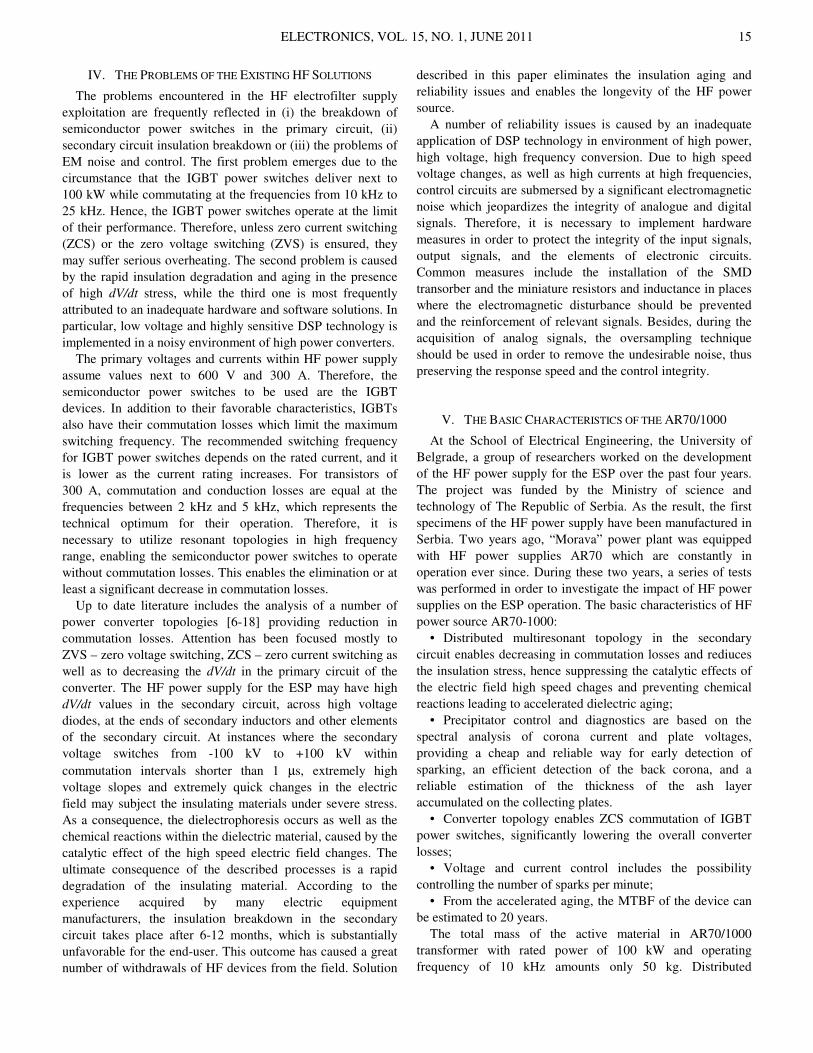
frequency of 10 kHz amounts only 50 kg. Distributed
ELECTRONICS, VOL. 15, NO. 1, JUNE 2011 16
multiresonant secondary circuit is made of conventional
reactive components having a relatively low weight, and it uses
standard HV diodes (Figs. 4−6). Within the secondary HV
rectifier, high speed diodes anre not required as the converter
topology enables the rectifier operation in ZVS mode. Besides,
it is the ZVS mode that reduces the dV/dt in the secondary
circuit and ensures the longevity of the insulation materials.
In comparison to standard 50 Hz sources including the
thyristor cabinet and the T/R group, the HF power supply
АR70/1000 is five times smaller in volume, about 5 times
lighter and up to 30% cheaper. It should be noticed that the HF
source features explained above provide a significant increase
in precipitation efficiency, contribute to a more favorable
shape of the line current, ensure much lower reactive power
and reduces significantly the erosion of the plates due to a
significant decrease in the spark energy. Due to the original
multiresonant topology, DSP unit for control and supervision
as well as the original solution of thermal handling, and
mechanical protection, the АR70/1000 meets the following
standards and regulations,
• Low Voltage Directive (73/23/EEC);
• EMC directive (89/336/EEC);
• CEI EN 60204-1, par. 6.2.3, 20.3, 20.4;
• IP Code, EN60529;
• CEI EN60800-3;
• EN60800-3/A11.
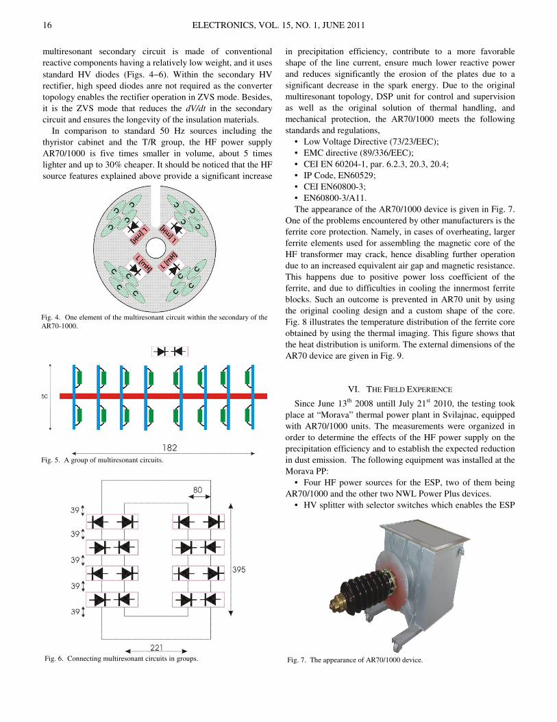
The appearance of the АR70/1000 device is given in Fig. 7.
One of the problems encountered by other manufacturers is the
ferrite core protection. Namely, in cases of overheating, larger
ferrite elements used for assembling the magnetic core of the
HF transformer may crack, hence disabling further operation
due to an increased equivalent air gap and magnetic resistance.
This happens due to positive power loss coefficient of the
ferrite, and due to difficulties in cooling the innermost ferrite
blocks. Such an outcome is prevented in AR70 unit by using
the original cooling design and a custom shape of the core.
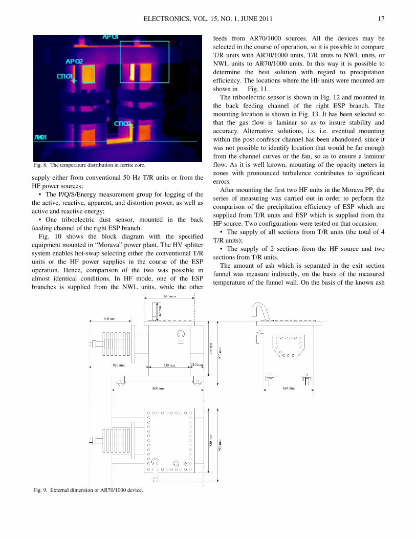
Fig. 8 illustrates the temperature distribution of the ferrite core
obtained by using the thermal imaging. This figure shows that
the heat distribution is uniform. The external dimensions of the
AR70 device are given in Fig. 9.
VI. THE FIELD EXPERIENCE
Since June 13th
2008 untill July 21st 2010, the testing took
place at “Morava” thermal power plant in Svilajnac, equipped
with AR70/1000 units. The measurements were organized in
order to determine the effects of the HF power supply on the
precipitation efficiency and to establish the expected reduction
in dust emission. The following equipment was installed at the
Morava PP:
• Four HF power sources for the ESP, two of them being
AR70/1000 and the other two NWL Power Plus devices.
• HV splitter with selector switches which enables the ESP
Fig. 4. One element of the multiresonant circuit within the secondary of the
АR70-1000.
Fig. 5. A group of multiresonant circuits.
Fig. 6. Connecting multiresonant circuits in groups.
Fig. 7. The appearance of АR70/1000 device.
ELECTRONICS, VOL. 15, NO. 1, JUNE 2011 17
supply either from conventional 50 Hz T/R units or from the
HF power sources;
• The P/Q/S/Energy measurement group for logging of the
the active, reactive, apparent, and distortion power, as well as
active and reactive energy;
• One triboelectric dust sensor, mounted in the back
feeding channel of the right ESP branch.
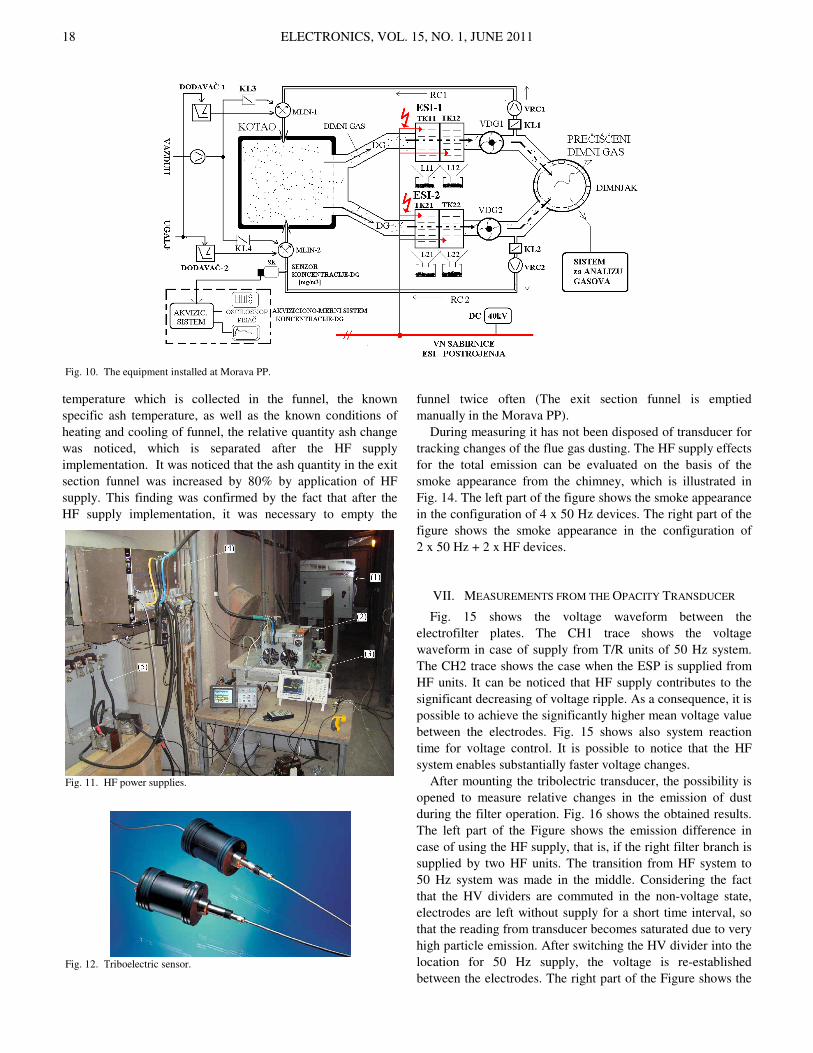
Fig. 10 shows the block diagram with the specified
equipment mounted in “Morava” power plant. The HV splitter
system enables hot-swap selecting either the conventional T/R
units or the HF power supplies in the course of the ESP
operation. Hence, comparison of the two was possible in
almost identical conditions. In HF mode, one of the ESP
branches is supplied from the NWL units, while the other
feeds from АR70/1000 sources. All the devices may be
selected in the course of operation, so it is possible to compare
T/R units with AR70/1000 units, T/R units to NWL units, or
NWL units to AR70/1000 units. In this way it is possible to
determine the best solution with regard to precipitation
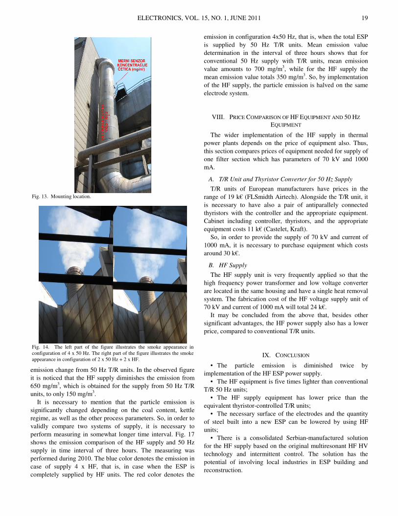
efficiency. The locations where the HF units were mounted are
shown in Fig. 11.
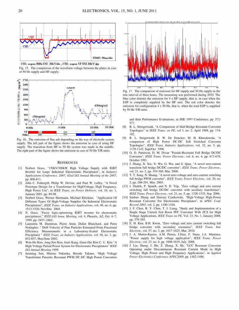
The triboelectric sensor is shown in Fig. 12 and mounted in
the back feeding channel of the right ESP branch. The
mounting location is shown in Fig. 13. It has been selected so
that the gas flow is laminar so as to insure stability and
accuracy. Alternative solutions, i.s. i.e. eventual mounting
within the post-confusor channel has been abandoned, since it
was not possible to identify location that would be far enough
from the channel curves or the fan, so as to ensure a laminar
flow. As it is well known, mounting of the opacity meters in
zones with pronounced turbulence contributes to significant
errors.
After mounting the first two HF units in the Morava PP, the
series of measuring was carried out in order to perform the
comparison of the precipitation efficiency of ESP which are
supplied from T/R units and ESP which is supplied from the
HF source. Two configurations were tested on that occasion:
• The supply of all sections from T/R units (the total of 4
T/R units);
• The supply of 2 sections from the HF source and two
sections from T/R units.
The amount of ash which is separated in the exit section
funnel was measure indirectly, on the basis of the measured
temperature of the funnel wall. On the basis of the known ash
Fig. 8. The temperature distribution in ferrite core.
Fig. 9. External dimension of АR70/1000 device.
ELECTRONICS, VOL. 15, NO. 1, JUNE 2011 18
temperature which is collected in the funnel, the known
specific ash temperature, as well as the known conditions of
heating and cooling of funnel, the relative quantity ash change
was noticed, which is separated after the HF supply
implementation. It was noticed that the ash quantity in the exit
section funnel was increased by 80% by application of HF
supply. This finding was confirmed by the fact that after the
HF supply implementation, it was necessary to empty the
funnel twice often (The exit section funnel is emptied
manually in the Morava PP).
During measuring it has not been disposed of transducer for
tracking changes of the flue gas dusting. The HF supply effects
for the total emission can be evaluated on the basis of the
smoke appearance from the chimney, which is illustrated in
Fig. 14. The left part of the figure shows the smoke appearance
in the configuration of 4 x 50 Hz devices. The right part of the
figure shows the smoke appearance in the configuration of
2 x 50 Hz + 2 x HF devices.
VII. MEASUREMENTS FROM THE OPACITY TRANSDUCER
Fig. 15 shows the voltage waveform between the
electrofilter plates. The CH1 trace shows the voltage
waveform in case of supply from T/R units of 50 Hz system.
The CH2 trace shows the case when the ESP is supplied from
HF units. It can be noticed that HF supply contributes to the
significant decreasing of voltage ripple. As a consequence, it is
possible to achieve the significantly higher mean voltage value
between the electrodes. Fig. 15 shows also system reaction
time for voltage control. It is possible to notice that the HF
system enables substantially faster voltage changes.
After mounting the tribolectric transducer, the possibility is
opened to measure relative changes in the emission of dust
during the filter operation. Fig. 16 shows the obtained results.
The left part of the Figure shows the emission difference in
case of using the HF supply, that is, if the right filter branch is
supplied by two HF units. The transition from HF system to
50 Hz system was made in the middle. Considering the fact
that the HV dividers are commuted in the non-voltage state,
electrodes are left without supply for a short time interval, so
that the reading from transducer becomes saturated due to very
high particle emission. After switching the HV divider into the
location for 50 Hz supply, the voltage is re-established
between the electrodes. The right part of the Figure shows the
Fig. 10. The equipment installed at Morava PP.
Fig. 11. HF power supplies.
Fig. 12. Тriboelectric sensor.
ELECTRONICS, VOL. 15, NO. 1, JUNE 2011 19
emission change from 50 Hz T/R units. In the observed figure
it is noticed that the HF supply diminishes the emission from
650 mg/m3, which is obtained for the supply from 50 Hz T/R
units, to only 150 mg/m3.
It is necessary to mention that the particle emission is
significantly changed depending on the coal content, kettle
regime, as well as the other process parameters. So, in order to
validly compare two systems of supply, it is necessary to
perform measuring in somewhat longer time interval. Fig. 17
shows the emission comparison of the HF supply and 50 Hz
supply in time interval of three hours. The measuring was
performed during 2010. The blue color denotes the emission in
case of supply 4 x HF, that is, in case when the ESP is
completely supplied by HF units. The red color denotes the
emission in configuration 4x50 Hz, that is, when the total ESP
is supplied by 50 Hz T/R units. Mean emission value
determination in the interval of three hours shows that for
conventional 50 Hz supply with T/R units, mean emission
value amounts to 700 mg/m3, while for the HF supply the
mean emission value totals 350 mg/m3. So, by implementation
of the HF supply, the particle emission is halved on the same
electrode system.
VIII. PRICE COMPARISON OF HF EQUIPMENT AND 50 HZ
EQUIPMENT
The wider implementation of the HF supply in thermal
power plants depends on the price of equipment also. Thus,
this section compares prices of equipment needed for supply of
one filter section which has parameters of 70 kV and 1000
mA.
A. T/R Unit and Thyristor Converter for 50 Hz Supply
T/R units of European manufacturers have prices in the
range of 19 k€ (FLSmidth Airtech). Alongside the T/R unit, it
is necessary to have also a pair of antiparallely connected
thyristors with the controller and the appropriate equipment.
Cabinet including controller, thyristors, and the appropriate
equipment costs 11 k€ (Castelet, Kraft).
So, in order to provide the supply of 70 kV and current of
1000 mA, it is necessary to purchase equipment which costs
around 30 k€.
B. HF Supply
The HF supply unit is very frequently applied so that the
high frequency power transformer and low voltage converter
are located in the same housing and have a single heat removal
system. The fabrication cost of the HF voltage supply unit of
70 kV and current of 1000 mA will total 24 k€.
It may be concluded from the above that, besides other
significant advantages, the HF power supply also has a lower
price, compared to conventional T/R units.
IX. CONCLUSION
• The particle emission is diminished twice by
implementation of the HF ESP power supply.
• The HF equipment is five times lighter than conventional
T/R 50 Hz units;
• The HF supply equipment has lower price than the
equivalent thyristor-controlled T/R units;
• The necessary surface of the electrodes and the quantity
of steel built into a new ESP can be lowered by using HF
units;
• There is a consolidated Serbian-manufactured solution
for the HF supply based on the original multiresonant HF HV
technology and intermittent control. The solution has the
potential of involving local industries in ESP building and
reconstruction.
Fig. 13. Mounting location.
Fig. 14. The left part of the figure illustrates the smoke appearance in
configuration of 4 x 50 Hz. The right part of the figure illustrates the smoke
appearance in configuration of 2 x 50 Hz + 2 x HF.
ELECTRONICS, VOL. 15, NO. 1, JUNE 2011 20
REFERENCES
[1] Norbert Grass, "150kV/300kW High Voltage Supply with IGBT
Inverter for Large Industrial Electrostatic Precipitator", in Industry
Applications Conference, 2007, 42nd IAS Annual Meeting of the 2007,
pp. 808-811.
[2] John C. Fothergill, Philip W. Devine, and Paul W. Lefley, "A Novel
Prototype Design for a Transformer for HighVoltage, High Frequency,
High Power Use", in IEEE Trans. on Power Delivery, vol. 16, no. 1,
January 2001. pp. 89-98.
[3] Norbert Grass, Werner Hartmann, Michael Klöckner, "Application Of
Different Types Of High-Voltage Supplies On Industrial Electrostatic
Precipitators", IEEE Trans. on Industry Applications, vol. 40, no. 6, pp.
1513-1520, Nov/Dec 2004.
[4] N. Grass, “Fuzzy logic-optimising IGBT inverter for electrostatic
precipitators,” IEEE-IAS Annu. Meeting, vol. 4, Phoenix, AZ, Oct. 4–7,
1999, pp. 2457–2462.
[5] Laurentiu M. Dumitran, Pierre Atten, Didier Blanchard, and Petru
Notingher, " Drift Velocity of Fine Particles Estimated From Fractional
Efficiency Measurements in a Laboratory-Scaled Electrostatic
Precipitator " IEEE Trans. on Industry Applications, vol. 38, no. 3, pp.
852-857, May/June 2002.
[6] Won-Ho Kim, Jong-Soo Kim, Iouri Kang, Geun-Hie Rim C. U. Kim "A
High Voltage Pulsed Power System for Electrostatic Precipitators" IEEE
IAS Annual Meeting 1999.
[7] Junming Sun, Mutsuo Nakaoka, Hiroshi Takano, "High Voltage
Transformer Parasitic Resonant PWM DC-DC High Power Converters
and their Performance Evaluations, in ISIE 1997 Conference, pp. 572-
577.
[8] R. L. Streigerwald, "A Comparison of Half-Bridge Resonant Converter
Topologies" in IEEE Trans. on PE, vol 3, no. 2, April 1988, pp. 174-
182.
[9] R. L. Steigerwald, R. W. De Doncker, M. H. Kheraluwala, "A
comparison of High Power DC-DC Soft Switched Converter
Topologies", IEEE Trans. Industry Applications, vol. 32, no. 5, pp.
1139-1145, Sept/Oct 1996.
[10] O. D. Patterson, D. M. Divan "Pseudo-Resonant Full Bridge DC/DC
Converter", IEEE Trans. Power Electron., vol. 6, no. 4, pp. 671-678,
October 1991.
[11] J. Zhang, X. Xie, X. Wu, G. Wu, and Z. Qian, "A novel zero-current
transition full bridge DC/DC converter", IEEE Trans. Power Electron.,
vol. 21, no. 2, pp. 354-360, Mar. 2006.
[12] T. T. Song, N. Huang, "A novel zero-voltage and zero-current switching
full bridge PWM converter", IEEE Trans. Power Electron., vol. 20, no.
2, pp. 286-291, Mar. 2005.
[13] J. Dudrik, P. Spanik, and N. D. Trip, "Zero voltage and zero current
switching full bridge DC/DC converter with auxiliary transformer",
IEEE Trans. Power Electron., vol. 21, no. 5, pp. 1328-1335, Sep. 2006.
[14] Sanbao Zheng and Darisuz Czarkowski, "High-Voltage High-Power
Resonant Converter For Electrostatic Precipitator", in APEC Conf.
Record 2003, vol. 2, pp. 1100-1104.
[15] J. F. Chen, R. Y. Chen, T. J. Liang, "Study and Implementation of a
Single Stage Current Fed Boost PFC Converter With ZCS for High
Voltage Applications, IEEE Trans on PE, Vol. 23, No. 1, January 2008,
pp. 379-385.
[16] E. H. Kim, B.H. Kwon, "Zero voltage and zero current switching full
bridge converter with secondary resonance", IEEE Trans. Ind.
Electron., vol. 57, no. 3, pp. 1017-1025, Mar. 2010.
[17] J. A. Martin-Ramos, A.M. Pernia, J.Diaz, F. Nuno, J.A. Martinez,
“Power supply for high voltage application”, IEEE Trans. Power
Electron., vol. 23, no. 4, pp. 1608-1619, July. 2008.
[18] J. Liu, Sheng, J. Shi, Z. Zhang, X. He, "LCC Resonant Converter
Operating under Discontinuous Resonant Current Mode in High
Voltage, High Power and High Frequency Applications", in Applied
Power Electronics Conference APEC2009, pp. 1482-1486.
Fig. 15. The comparison of the waveform voltage between the plates in case
of 50 Hz supply and HF supply.
Fig. 16. The emission of flue ash depending on the way of electrode system
supply. The left part of the figure shows the emission in case of using HF
supply. The transition from HF to 50 Hz system was made in the middle.
The right part of the figure shows the emission in case of 50 Hz T/R units.
Fig. 17. The comparison of emission for HF supply and 50 Hz supply in the
tme interval of three hours. The measuring was performed during 2010. The
blue color denotes the emission for 4 x HF supply, that is, in case when the
ESP is completely supplied by the HF unit. The red color denotes the
emission for configuration 4 x 50 Hz, that is, when the total ESP is supplied
by 50 Hz T/R units.