Embed Size (px)
Citation preview
High frequency DC welding power supply UF25B
1
UF25B
Directory 1 Introducion section····················································································································· 2
1.1 Features introduction ··································································································· 2 1.2 UF25 physical property ································································································ 3 1.3 UF25 main circuit diagram ·························································································· 3
2 Function module························································································································· 4 3 Function introduction ················································································································ 5
3.1 Front panel function introduction················································································ 5 3.2 Rear panel function introduction ················································································· 7 3.3 Display introduction ····································································································11
3.3.1 UF25 display content construction introduction ··············································11 3.3.2 Main menu display introduction ·········································································11 3.3.3 A.WELDING MONITER introduction·······························································11 3.3.4 B.SCH PROGRAM introduction ······································································· 13
3.3.4.1 Weld parameter setting introduction······················································· 13 3.3.4.2 Welding monitor parameter setting introduction···································· 15
3.3.5 C.OPTION SETTING introduction ··································································· 16 3.3.6 D.CALIBRATION function introduction ·························································· 18
4 Work mode and weld parameter introduction········································································ 19 4.1 Work mode introduction ···························································································· 19 4.2 ‘BASIC’weld work mode ······························································································ 19
4.2.1 Different welder setting and action introduction ··············································· 19 4.2.2 Weld parameter introduction ············································································· 23 4.2.3 CHANGE SCH function ····················································································· 24
4.3 ‘LINK’weld work mode ································································································ 25 4.3.1 Installation and setting ······················································································· 25 4.3.2 Weld sction introduction····················································································· 25 4.3.3 Weld parameter introduction ············································································· 26
4.4 ‘ROLLSPOT’work mode ······························································································ 27 4.4.1 Installation and setting ······················································································· 27 4.4.2 Weld action introduction ···················································································· 27 4.4.3 Weld parameter introduction ············································································· 28
4.5 ‘DOUBLE HEAD’work mode ······················································································ 29 4.5.1 Installation and setting ······················································································· 29 4.5.2 Weld action introduction ···················································································· 30 4.5.3 Weld parameter introduction ············································································· 31
4.6 ‘PLC’work mode ··········································································································· 32 4.6.1 Connecting signal introduction ·········································································· 32 4.6.2 Installation and setting ······················································································· 35 4.6.3 Weld action introduction ···················································································· 35 4.6.4 Weld parameter introduction ············································································· 35
PDF 文件使用 "pdfFactory Pro" 试用版本创建 www.fineprint.cn
High frequency DC welding power supply UF25B
2
1 Introduction section UF25B is a inversion DC welding power supply,which convene multiple advanced functions.Not only have excellent welding ability,also can easily match various types weld head and be embedded into the automated welding system as welding module applications.
1.1 Features introduction l High inverse frequency can control the welding energy much more accurate and rapid.
l Having double-pulse welding function.
l Each pulse has following functions:slowly rise,slowly drop,welding time,welding
energy and set the monitor data.
l Various welding energy control mode,constant current,constant voltage and constant power can match welding requirements of different shape materials .
l Multiple welding work mode:Common Point Welding,ROLL/SPOT mode,Series
Weldin,Double-head Control and PLC Control.
l Display the welding result as word and graphic form.Make debugging more simple and intutive.
l Having the welding quality monitor and output functions can automaticly check out the
products in bad quality.
l Having series communication capability.
PDF 文件使用 "pdfFactory Pro" 试用版本创建 www.fineprint.cn
High frequency DC welding power supply UF25B
3
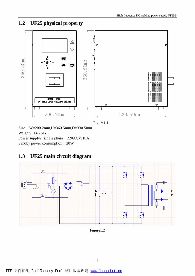
1.2 UF25 physical property
Figure1.1
Size:W=200.2mm,H=360.5mm,D=330.5mm Weight:14.2KG Power supply:single phase,220ACV/10A Sandby power consumption:30W
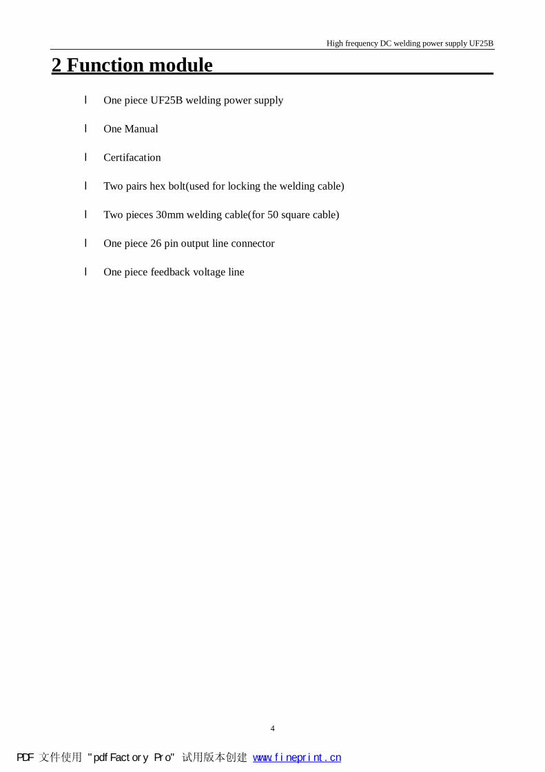
1.3 UF25 main circuit diagram
Figure1.2
PDF 文件使用 "pdfFactory Pro" 试用版本创建 www.fineprint.cn
High frequency DC welding power supply UF25B
4
2 Function module
l One piece UF25B welding power supply l One Manual
l Certifacation
l Two pairs hex bolt(used for locking the welding cable)
l Two pieces 30mm welding cable(for 50 square cable)
l One piece 26 pin output line connector
l One piece feedback voltage line
PDF 文件使用 "pdfFactory Pro" 试用版本创建 www.fineprint.cn
High frequency DC welding power supply UF25B
5
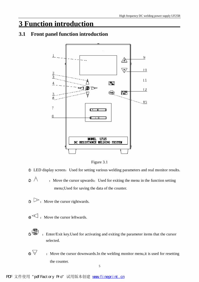
3 Function introduction 3.1 Front panel function introduction
Figure 3.1
○1 LED display screen:Used for setting various welding parameters and real monitor results.
○2 :Move the cursor upwards;Used for exiting the menu in the function setting
menu;Used for saving the data of the counter.
○3 :Move the cursor rightwards.
○4 :Move the cursor leftwards.
○5 :Enter/Exit key.Used for activating and exiting the parameter items that the cursor selected.
○6 :Move the cursor downwards.In the welding monitor menu,it is used for resetting
the counter.
PDF 文件使用 "pdfFactory Pro" 试用版本创建 www.fineprint.cn
High frequency DC welding power supply UF25B
6
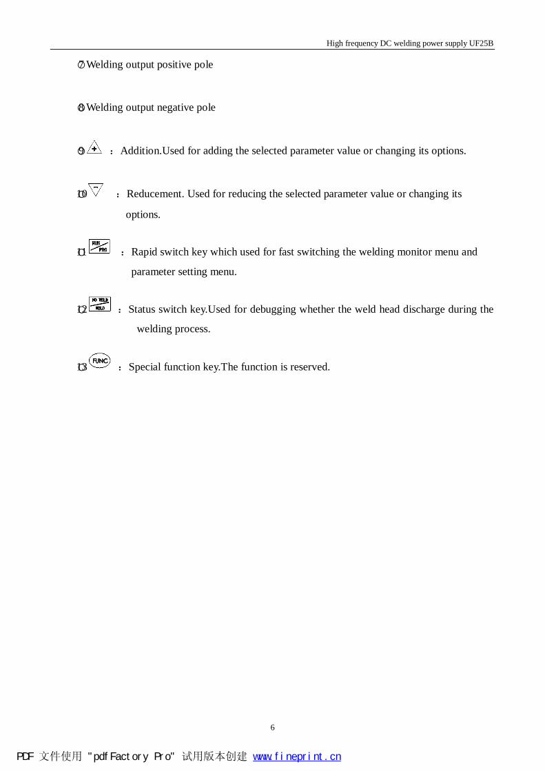
○7 Welding output positive pole
○8 Welding output negative pole
○9 :Addition.Used for adding the selected parameter value or changing its options.
○10 :Reducement. Used for reducing the selected parameter value or changing its
options.
○11 :Rapid switch key which used for fast switching the welding monitor menu and
parameter setting menu.
○12 :Status switch key.Used for debugging whether the weld head discharge during the
welding process.
○13 :Special function key.The function is reserved.
PDF 文件使用 "pdfFactory Pro" 试用版本创建 www.fineprint.cn
High frequency DC welding power supply UF25B
7
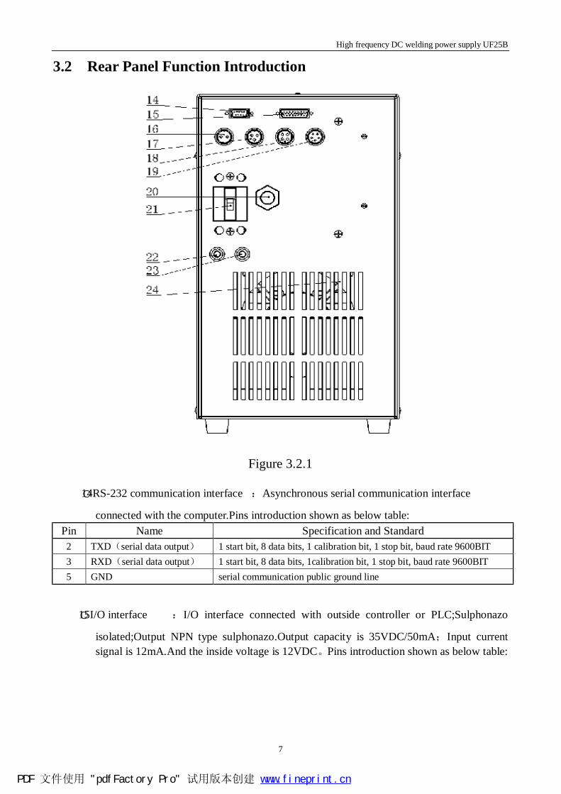
3.2 Rear Panel Function Introduction
Figure 3.2.1
○14RS-232 communication interface :Asynchronous serial communication interface
connected with the computer.Pins introduction shown as below table: Pin Name Specification and Standard
2 TXD(serial data output) 1 start bit, 8 data bits, 1 calibration bit, 1 stop bit, baud rate 9600BIT 3 RXD(serial data output) 1 start bit, 8 data bits, 1calibration bit, 1 stop bit, baud rate 9600BIT 5 GND serial communication public ground line
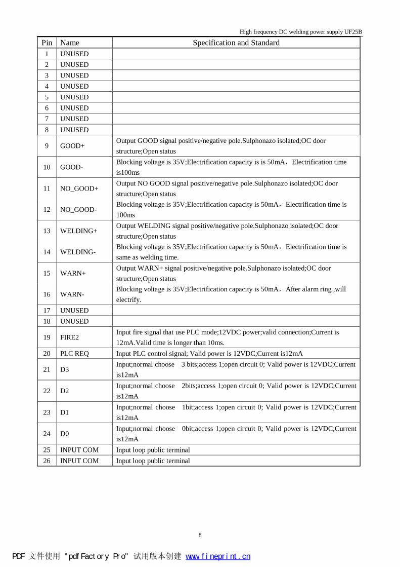
○15I/O interface :I/O interface connected with outside controller or PLC;Sulphonazo
isolated;Output NPN type sulphonazo.Output capacity is 35VDC/50mA;Input current signal is 12mA.And the inside voltage is 12VDC。Pins introduction shown as below table:
PDF 文件使用 "pdfFactory Pro" 试用版本创建 www.fineprint.cn
High frequency DC welding power supply UF25B
8
Pin Name Specification and Standard 1 UNUSED 2 UNUSED 3 UNUSED 4 UNUSED 5 UNUSED 6 UNUSED 7 UNUSED 8 UNUSED
9 GOOD+ Output GOOD signal positive/negative pole.Sulphonazo isolated;OC door structure;Open status
10 GOOD- Blocking voltage is 35V;Electrification capacity is is 50mA,Electrification time is100ms
11 NO_GOOD+ Output NO GOOD signal positive/negative pole.Sulphonazo isolated;OC door structure;Open status
12 NO_GOOD- Blocking voltage is 35V;Electrification capacity is 50mA,Electrification time is 100ms
13 WELDING+ Output WELDING signal positive/negative pole.Sulphonazo isolated;OC door structure;Open status
14 WELDING- Blocking voltage is 35V;Electrification capacity is 50mA,Electrification time is same as welding time.
15 WARN+ Output WARN+ signal positive/negative pole.Sulphonazo isolated;OC door structure;Open status
16 WARN- Blocking voltage is 35V;Electrification capacity is 50mA,After alarm ring ,will electrify.
17 UNUSED 18 UNUSED
19 FIRE2 Input fire signal that use PLC mode;12VDC power;valid connection;Current is 12mA.Valid time is longer than 10ms.
20 PLC REQ Input PLC control signal; Valid power is 12VDC;Current is12mA
21 D3 Input;normal choose 3 bits;access 1;open circuit 0; Valid power is 12VDC;Current is12mA
22 D2 Input;normal choose 2bits;access 1;open circuit 0; Valid power is 12VDC;Current is12mA
23 D1 Input;normal choose 1bit;access 1;open circuit 0; Valid power is 12VDC;Current is12mA
24 D0 Input;normal choose 0bit;access 1;open circuit 0; Valid power is 12VDC;Current is12mA
25 INPUT COM Input loop public terminal 26 INPUT COM Input loop public terminal
PDF 文件使用 "pdfFactory Pro" 试用版本创建 www.fineprint.cn
High frequency DC welding power supply UF25B
9
○16 Electromagnetic valve drive interface :Used for connecting and drive the electromagnetic
valve.Output voltage is 220ACV/0.4A。Pins introduction shown as below table:
Pin Name Specification and Standard 1 COM Output; electromagnetic valve drive public terminal 2 AIR1 Output;A electromagnetic valve drive;220VAC/0.4A 3 AIR2 Output;B electromagnetic valve;220VAC/0.4A (used in double weld head mode)
○17Fire switch interface :Used to connect dischage switch. Pins introduction shown as below
table:
Pin Name Specification and Standard
1 FIRE RETURN
Input;Fire signal input circuit.
2 UNUSED
3 FIRE Input;Fire signal;Optiacl couple; Power 12VDC;Effective electrification current 12mA ;Minimum duration time is at least 10ms
○18Foot switch input interface :Connect foot switch under the level 1 foot switch or level 2
foot switch or double weld head mode.
Pin Name Specification and Standard 1 RETURN Input return;Public terminal.
2 FOOT2 Input;Level 2 foot switch signal;Sulphonazo isolated; Powe 12VDC;Effective electrification current 12mA; Minimum duration time is at least 10ms
3 FOOT1 Input;Level 1 foot switch signal used for double weld head mode;Sulphonazo isolated; Powe 12VDC;Effective electrification current 12mA; Minimum duration time longer than 10ms.
4 FOOT3 Input;Level 2 foot switch signal used for double weld head mode;Sulphonazo isolated; Powe 12VDC;Effective electrification current 12mA; Minimum duration time is at least 10ms.
○19Welding voltage input interface :Used for connecting welding voltage detection line
which is no need to distinguish the pole.
○20Input power line interface :Used for connecting input power line.Specification:
220ACV~240ACV.
○21Breaker : Used for electrifying or cutting off the input
power.Having over-loading and short circuit cutting off functions.
PDF 文件使用 "pdfFactory Pro" 试用版本创建 www.fineprint.cn
High frequency DC welding power supply UF25B
10
○22Fuse holder 1 :Specification is 1A/220ACV.
○23Fuse holder 2 :Specification is 1A/220ACV.
○24Heat radiation window :Used for discharging heat.Must make sure the distance to
the nearest obstacle is at least 15 cm.
PDF 文件使用 "pdfFactory Pro" 试用版本创建 www.fineprint.cn
High frequency DC welding power supply UF25B
11
3.3 Display introduction
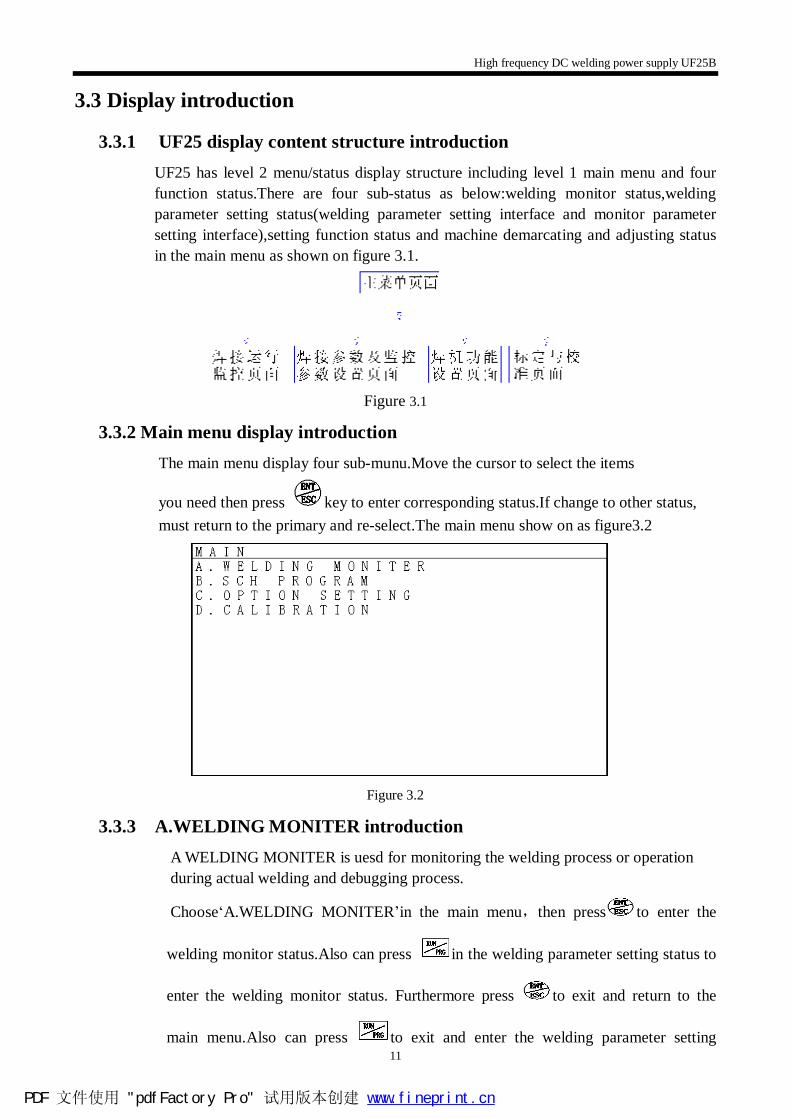
3.3.1 UF25 display content structure introduction UF25 has level 2 menu/status display structure including level 1 main menu and four function status.There are four sub-status as below:welding monitor status,welding parameter setting status(welding parameter setting interface and monitor parameter setting interface),setting function status and machine demarcating and adjusting status in the main menu as shown on figure 3.1.
Figure 3.1
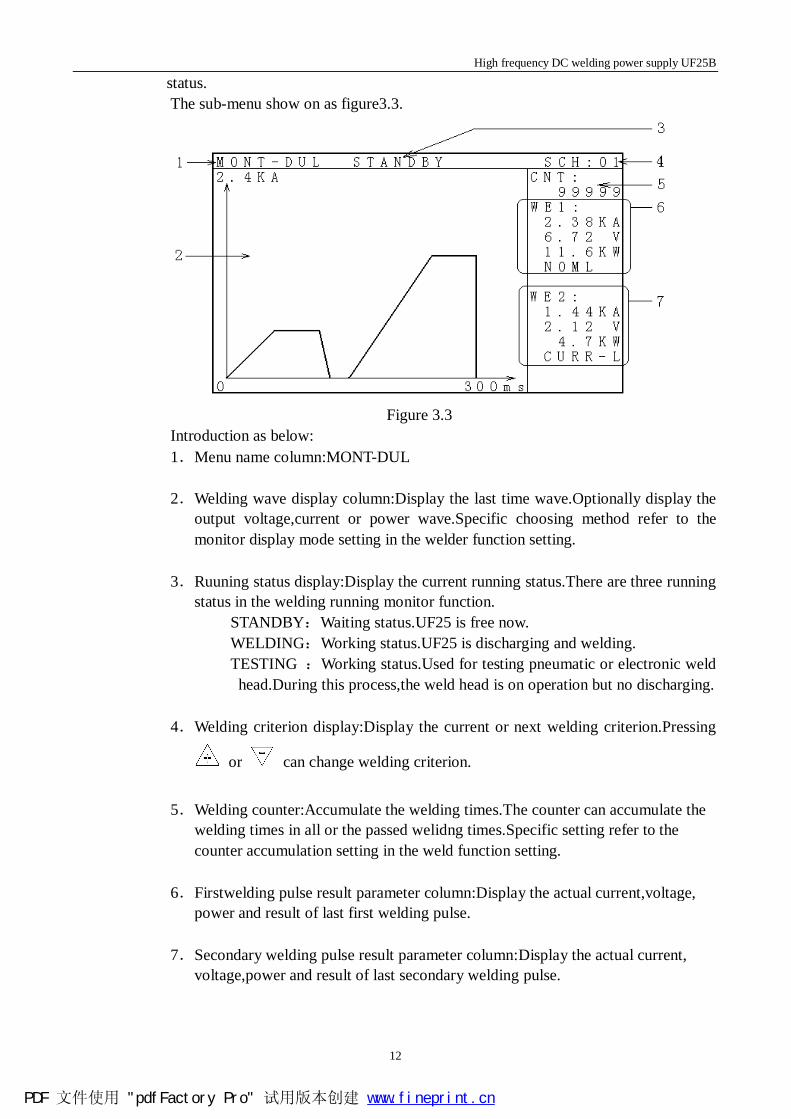
3.3.2 Main menu display introduction The main menu display four sub-munu.Move the cursor to select the items
you need then press key to enter corresponding status.If change to other status, must return to the primary and re-select.The main menu show on as figure3.2
Figure 3.2
3.3.3 A.WELDING MONITER introduction A WELDING MONITER is uesd for monitoring the welding process or operation during actual welding and debugging process.
Choose‘A.WELDING MONITER’in the main menu,then press to enter the
welding monitor status.Also can press in the welding parameter setting status to
enter the welding monitor status. Furthermore press to exit and return to the
main menu.Also can press to exit and enter the welding parameter setting
PDF 文件使用 "pdfFactory Pro" 试用版本创建 www.fineprint.cn
High frequency DC welding power supply UF25B
12
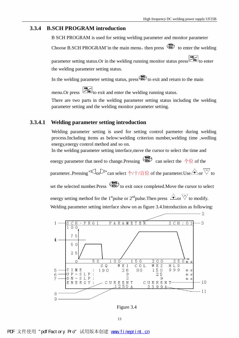
status. The sub-menu show on as figure3.3.
Figure 3.3
Introduction as below: 1.Menu name column:MONT-DUL 2.Welding wave display column:Display the last time wave.Optionally display the
output voltage,current or power wave.Specific choosing method refer to the monitor display mode setting in the welder function setting.
3.Ruuning status display:Display the current running status.There are three running
status in the welding running monitor function. STANDBY:Waiting status.UF25 is free now. WELDING:Working status.UF25 is discharging and welding. TESTING :Working status.Used for testing pneumatic or electronic weld head.During this process,the weld head is on operation but no discharging.
4.Welding criterion display:Display the current or next welding criterion.Pressing
or can change welding criterion.
5.Welding counter:Accumulate the welding times.The counter can accumulate the
welding times in all or the passed welidng times.Specific setting refer to the counter accumulation setting in the weld function setting.
6.Firstwelding pulse result parameter column:Display the actual current,voltage,
power and result of last first welding pulse.
7.Secondary welding pulse result parameter column:Display the actual current, voltage,power and result of last secondary welding pulse.
PDF 文件使用 "pdfFactory Pro" 试用版本创建 www.fineprint.cn
High frequency DC welding power supply UF25B
13
3.3.4 B.SCH PROGRAM introduction B SCH PROGRAM is used for setting welding parameter and monitor parameter
Choose B.SCH PROGRAM’in the main menu,then press to enter the welding
parameter setting status.Or in the welding running monitor status press to enter the welding parameter setting status.
In the welding parameter setting status, press to exit and return to the main
menu.Or press to exit and enter the welding running status. There are two parts in the welding parameter setting status including the welding parameter setting and the welding monitor parameter setting.
3.3.4.1 Welding parameter setting introduction Welding parameter setting is used for setting control parmeter during welding process.Including items as below:welding criterion number,welding time ,wedling energy,energy control method and so on. In the welding parameter setting interface,move the cursor to select the time and
energy parameter that need to change.Pressing can select the 个位 of the
parameter..Pressing or can select个/十/百位 of the parameter.Use or to
set the selected number.Press to exit once completed.Move the cursor to select
energy setting method for the 1stpulse or 2ndpulse.Then press or to modify.
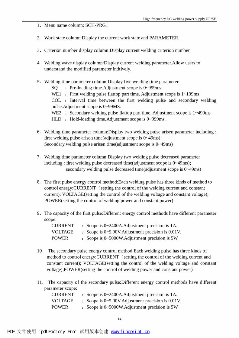
Welding parameter setting interface show on as figure 3.4.Introduction as following:
Figure 3.4
PDF 文件使用 "pdfFactory Pro" 试用版本创建 www.fineprint.cn
High frequency DC welding power supply UF25B
14
1.Menu name column: SCH-PRG1 2.Work state column:Display the current work state and PARAMETER.
3.Criterion number display column:Display current welding criterion number.
4.Welding wave display column:Display current welding parameter.Allow users to
understand the modified parameter intitively.
5.Welding time parameter column:Display five welding time parameter. SQ :Pre-loading time.Adjustment scope is 0~999ms. WE1 :First welding pulse flattop part time. Adjustment scope is 1~199ms COL :Interval time between the first welding pulse and secondary welding pulse.Adjustment scope is 0~99MS. WE2 :Secondary welding pulse flattop part time. Adjustment scope is 1~499ms HLD :Hold-loading time.Adjustment scope is 0~999ms.
6.Welding time parameter column:Display two welding pulse arisen parameter including : first welding pulse arisen time(adjustment scope is 0~49ms); Secondary welding pulse arisen time(adjustment scope is 0~49ms)
7.Welding time parameter column:Display two welding pulse decreased parameter
including : first welding pulse decreased time(adjustment scope is 0~49ms); secondary welding pulse decreased time(adjustment scope is 0~49ms)
8.The first pulse energy control method:Each welding pulse has three kinds of method to
control energy:CURRENT(setting the control of the welding current and constant current); VOLTAGE(setting the control of the welding voltage and constant voltage); POWER(setting the control of welding power and constant power)
9.The capacity of the first pulse:Different energy control methods have different parameter
scope: CURRENT :Scope is 0~2400A.Adjustment precision is 1A. VOLTAGE :Scope is 0~5.00V.Adjustment precision is 0.01V. POWER :Scope is 0~5000W.Adjustment precision is 5W.
10. The secondary pulse energy control method:Each welding pulse has three kinds of method to control energy:CURRENT(setting the control of the welding current and
constant current); VOLTAGE(setting the control of the welding voltage and constant voltage);POWER(setting the control of welding power and constant power).
11. The capacity of the secondary pulse:Different energy control methods have different
parameter scope: CURRENT :Scope is 0~2400A.Adjustment precision is 1A. VOLTAGE :Scope is 0~5.00V.Adjustment precision is 0.01V. POWER :Scope is 0~5000W.Adjustment precision is 5W.
PDF 文件使用 "pdfFactory Pro" 试用版本创建 www.fineprint.cn
High frequency DC welding power supply UF25B
15
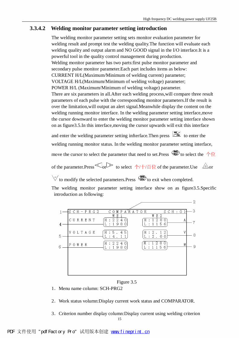
3.3.4.2 Welding monitor parameter setting introduction The welding monitor parameter setting sets monitor evaluation parameter for welding result and prompt test the welding quality.The function will evaluate each welding quality and output alarm and NO GOOD signal in the I/O interface.It is a powerful tool in the quality control management during production. Welding monitor parameter has two parts:first pulse monitor parameter and secondary pulse monitor parameter.Each part includes items as below: CURRENT H/L(Maximum/Minimum of welding current) parameter; VOLTAGE H/L(Maximum/Minimum of welding voltage) parameter; POWER H/L (Maximum/Minimum of welding voltage) parameter. There are six parameters in all.After each welding process,will compare three result parameters of each pulse with the corresponding monitor parameters.If the result is over the limitation,will output an alert signal.Meanwhile display the content on the welding running monitor interface. In the welding parameter setting interface,move the cursor downward to enter the welding monitor parameter setting interface shown on as figure3.5.In this interface,moving the cursor upwards will exit this interface
and enter the welding parameter setting infterface.Then press to enter the
welding running monitor status. In the welding monitor parameter setting interface,
move the cursor to select the parameter that need to set.Press to select the 个位
of the parameter.Press or to select 个/十/百位 of the parameter.Use or
to modify the selected parameters.Press to exit when completed.
The welding monitor parameter setting interface show on as figure3.5.Specific introduction as following:
Figure 3.5
1.Menu name column: SCH-PRG2 2.Work status volumn:Display current work status and COMPARATOR.
3.Criterion number display column:Display current using welding criterion
PDF 文件使用 "pdfFactory Pro" 试用版本创建 www.fineprint.cn
High frequency DC welding power supply UF25B
16
4.CURRENT H/L of WE1.The unit is A.
5.VOLTAGE H/L of WE1.The unit is V.
6.POWER H/L of WE1.The unit is W.
7.CURRENT H/L of WE2.The unit is A.
8.VOLTAGE H/L of WE2.The unit is V.
9.POWER H/L of WE2.The unit is W.
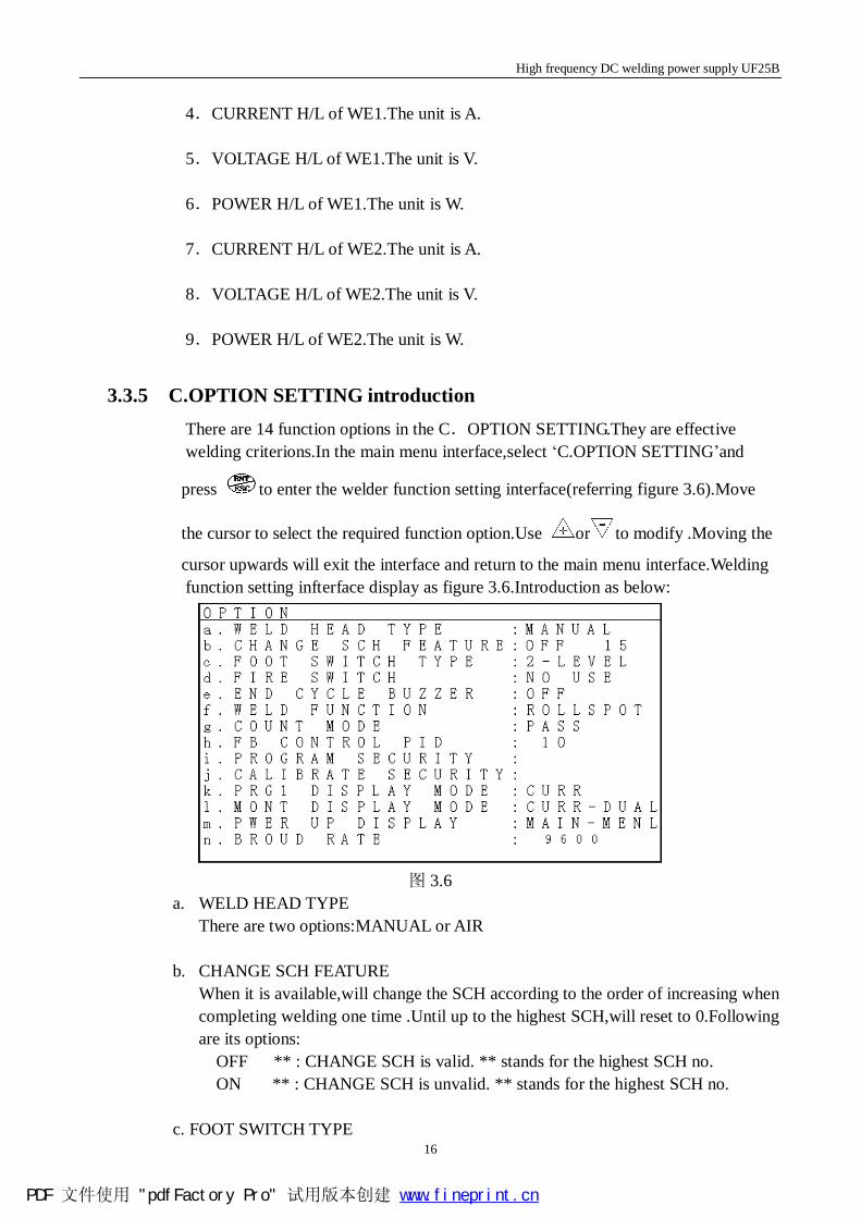
3.3.5 C.OPTION SETTING introduction There are 14 function options in the C.OPTION SETTING.They are effective welding criterions.In the main menu interface,select ‘C.OPTION SETTING’and
press to enter the welder function setting interface(referring figure 3.6).Move
the cursor to select the required function option.Use or to modify .Moving the
cursor upwards will exit the interface and return to the main menu interface.Welding function setting infterface display as figure 3.6.Introduction as below:
图 3.6
a. WELD HEAD TYPE There are two options:MANUAL or AIR
b. CHANGE SCH FEATURE
When it is available,will change the SCH according to the order of increasing when completing welding one time .Until up to the highest SCH,will reset to 0.Following are its options: OFF ** : CHANGE SCH is valid. ** stands for the highest SCH no. ON ** : CHANGE SCH is unvalid. ** stands for the highest SCH no.
c. FOOT SWITCH TYPE
PDF 文件使用 "pdfFactory Pro" 试用版本创建 www.fineprint.cn
High frequency DC welding power supply UF25B
17
The option is mainly used for air drive or electrifity drive welding Head.contain two sub-options:
1-LEVEL 2-LEVEL
c. FIRE SWITCH Show whether use the fire switch.Trigger the discharge welding and then the fire switch inside the weld head is available.Also can use foot switch to trigger.Two options offer to select:
USE:FIRE SWITCH is valid.Use it to trigger the welding action. NO USE:FIRE SWTICH is invalid.Use foot switch to activate.
d. END CYCLE BUZZER
Means whether buzzer after each welding.Options as below: ON :Buzzer after each welding OFF:Not buzzer after each welding
e. WELD FUNCTION There are four different welding methods offered:
BASIC。 LINK ROLLSPOT DOUBLE HEAD (If you want to know the details,please refer welding method and control parameter introduction)
f. COUNT MODE
Used for accumulating the welding times Two options:
ALL:The counter will add 1 after each welding completed. PASS:The counter only accumulate the passed welding
g. FB CONTROL PID Feedback control PID adjustment constant.The adjustment scope is 0~9.When the value is greater,the welding energy amendment will be more fast.But the fluctuation will also be greater.So should modify according to the actual welding wave.
i. PROGRAM SECURITY:The function is reserved.
j. CALIBRATE SECURITY: The function is reserved. k. PRG1 DISPLAY MODE
Used for displaying wave in the welding parameter setting interface Include three options : CURR shows welding current wave VOL shows welding voltage wave
PDF 文件使用 "pdfFactory Pro" 试用版本创建 www.fineprint.cn
High frequency DC welding power supply UF25B
18
PWR shows welding power wave
l. MONT DISPLAY MODE Used for displaying wave in the welding running monitor interface Include three options:
CURR shows welding current wave VOL shows welding voltage wave PWR shows welding power wave
m. POWER UP DISPLAY Used for displaying the interface after the machine electrifying. Include three options:
MAIN-MENL:Display the main menu infterface after the machine electrifying PRG1-MENL:Display the welding parameter setting infterce after the machine
electrifying MONT-MENL:Display the welding running monitor interface after the machine
electrifying n. BROUD RATE: The function is reserved.
3.3.6 D.CALIBRATION function introduction Used for welder parameter calibration and repair. The function is reserved just used
inside of welding factory .
PDF 文件使用 "pdfFactory Pro" 试用版本创建 www.fineprint.cn
High frequency DC welding power supply UF25B
19
4 Work mode and welding parameter introduction 4.1 Work mode introduction UF25 has five work modes: ‘BASIC’(basic welding mode); ‘LINK’(link welding Mode); ‘ROLL/SPOT'(roll/seam welding mode); ‘DOUBLE HEAD'(double head mode) ‘PLC’(programmable controller mode)
4.2 ‘BASIC’mode Used for general point welding.Can set single pulse or double pulse according to actual requirements during welding process.Furthermore all the welding and monitor parameters are valid. Weld head can be used pneumatic, electric, or mechanical-type institution.
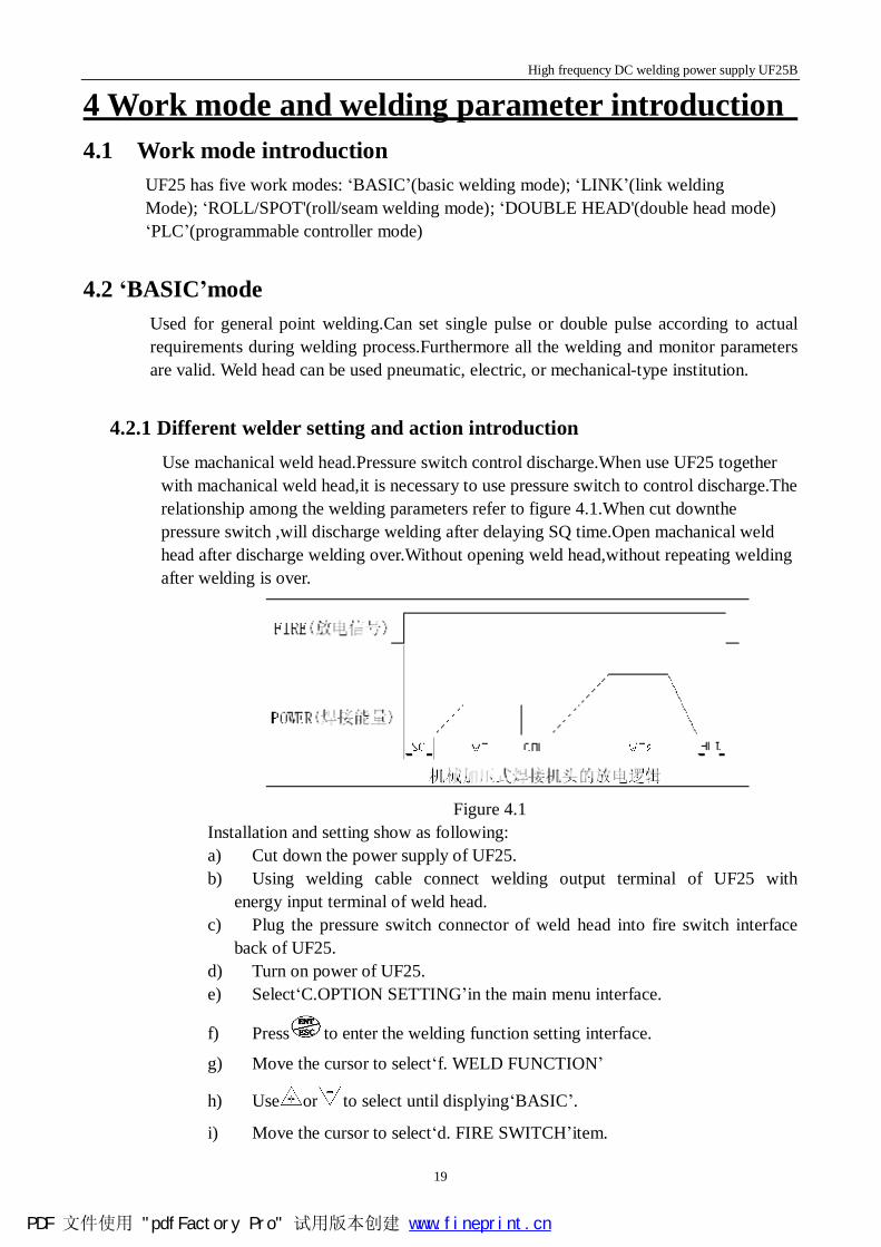
4.2.1 Different welder setting and action introduction Use machanical weld head.Pressure switch control discharge.When use UF25 together
with machanical weld head,it is necessary to use pressure switch to control discharge.The relationship among the welding parameters refer to figure 4.1.When cut downthe pressure switch ,will discharge welding after delaying SQ time.Open machanical weld head after discharge welding over.Without opening weld head,without repeating welding after welding is over.
Figure 4.1
Installation and setting show as following: a) Cut down the power supply of UF25. b) Using welding cable connect welding output terminal of UF25 with
energy input terminal of weld head. c) Plug the pressure switch connector of weld head into fire switch interface
back of UF25. d) Turn on power of UF25. e) Select‘C.OPTION SETTING’in the main menu interface.
f) Press to enter the welding function setting interface.
g) Move the cursor to select‘f. WELD FUNCTION’
h) Use or to select until displying‘BASIC’.
i) Move the cursor to select‘d. FIRE SWITCH’item.
PDF 文件使用 "pdfFactory Pro" 试用版本创建 www.fineprint.cn
High frequency DC welding power supply UF25B
20
j) Use or to select until displaying‘USE’.
k) Use to return the main menu from the welding function setting interface
l) Operation is complete.
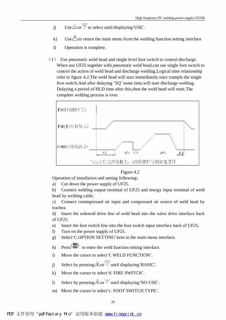
(1) Use pneumatic weld head and single level foot switch to control discharge. When use UF25 together with pneumatic weld head,can use single foot switch to control the action of weld head and discharge welding.Logical time relationship refer to figure 4.2.The weld head will start immediately once trample the single foot switch.And after delaying ‘SQ’ some time,will start discharge welding. Delaying a period of HLD time after this,then the weld head will reset.The complete welding process is over.
Figure 4.2
Operation of installation and setting following: a) Cut down the power supply of UF25. b) Connect welding output terminal of UF25 and energy input terminal of weld head by welding cable. c) Connect commpressed air input and compressed air source of weld head by trachea. d) Insert the solenoid drive line of weld head into the valve drive interface back of UF25. e) Insert the foot switch line into the foot switch input interface back of UF25. f) Turn on the power supply of UF25. g) Select‘C.OPTION SETTING’item in the main menu interface.
h) Press to enter the weld function setting interface.
i) Move the cursor to select‘f. WELD FUNCTION’.
j) Select by pressing or until displaying‘BASIC’.
k) Move the cursor to select‘d. FIRE SWITCH’.
l) Select by pressing or until displaying‘NO USE’.
m) Move the cursor to select‘c. FOOT SWITCH TYPE’.
PDF 文件使用 "pdfFactory Pro" 试用版本创建 www.fineprint.cn
High frequency DC welding power supply UF25B
21
n) Select by pressing or until displaying‘1-LEVEL’.
o) Press and return to the main menu from the weld function setting interface.
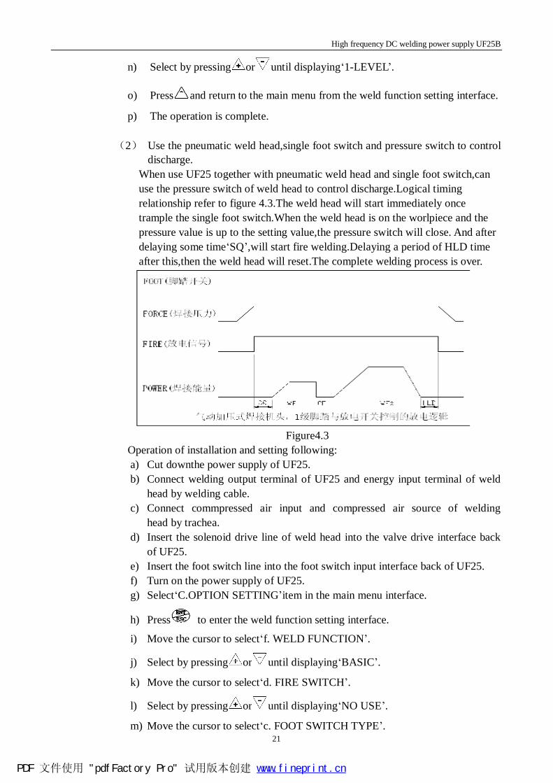
p) The operation is complete. (2) Use the pneumatic weld head,single foot switch and pressure switch to control
discharge. When use UF25 together with pneumatic weld head and single foot switch,can use the pressure switch of weld head to control discharge.Logical timing relationship refer to figure 4.3.The weld head will start immediately once trample the single foot switch.When the weld head is on the worlpiece and the pressure value is up to the setting value,the pressure switch will close. And after delaying some time‘SQ’,will start fire welding.Delaying a period of HLD time after this,then the weld head will reset.The complete welding process is over.
Figure4.3
Operation of installation and setting following: a) Cut downthe power supply of UF25. b) Connect welding output terminal of UF25 and energy input terminal of weld
head by welding cable. c) Connect commpressed air input and compressed air source of welding
head by trachea. d) Insert the solenoid drive line of weld head into the valve drive interface back
of UF25. e) Insert the foot switch line into the foot switch input interface back of UF25. f) Turn on the power supply of UF25. g) Select‘C.OPTION SETTING’item in the main menu interface.
h) Press to enter the weld function setting interface.
i) Move the cursor to select‘f. WELD FUNCTION’.
j) Select by pressing or until displaying‘BASIC’.
k) Move the cursor to select‘d. FIRE SWITCH’.
l) Select by pressing or until displaying‘NO USE’.
m) Move the cursor to select‘c. FOOT SWITCH TYPE’.
PDF 文件使用 "pdfFactory Pro" 试用版本创建 www.fineprint.cn
High frequency DC welding power supply UF25B
22
n) Select by pressing or until displaying‘1-LEVEL’.
o) Press .Return to the main menu from the weld function setting
Interface. p) The operation is complete.
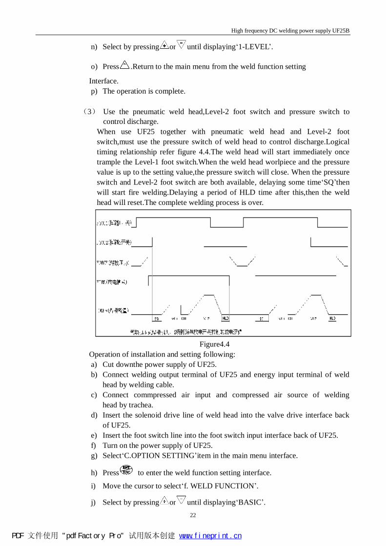
(3) Use the pneumatic weld head,Level-2 foot switch and pressure switch to
control discharge. When use UF25 together with pneumatic weld head and Level-2 foot switch,must use the pressure switch of weld head to control discharge.Logical timing relationship refer figure 4.4.The weld head will start immediately once trample the Level-1 foot switch.When the weld head worlpiece and the pressure value is up to the setting value,the pressure switch will close. When the pressure switch and Level-2 foot switch are both available, delaying some time‘SQ’then will start fire welding.Delaying a period of HLD time after this,then the weld head will reset.The complete welding process is over.
Figure4.4
Operation of installation and setting following: a) Cut downthe power supply of UF25. b) Connect welding output terminal of UF25 and energy input terminal of weld
head by welding cable. c) Connect commpressed air input and compressed air source of welding
head by trachea. d) Insert the solenoid drive line of weld head into the valve drive interface back
of UF25. e) Insert the foot switch line into the foot switch input interface back of UF25. f) Turn on the power supply of UF25. g) Select‘C.OPTION SETTING’item in the main menu interface.
h) Press to enter the weld function setting interface.
i) Move the cursor to select‘f. WELD FUNCTION’.
j) Select by pressing or until displaying‘BASIC’.
PDF 文件使用 "pdfFactory Pro" 试用版本创建 www.fineprint.cn
High frequency DC welding power supply UF25B
23
k) Move the cursor to select‘d. FIRE SWITCH’.
l) Select by pressing or until displaying‘NO USE’.
m) Move the cursor to select‘c. FOOT SWITCH TYPE’.
n) Select by pressing or until displaying‘2-LEVEL’.
o) Press .Return to the main menu from the weld function setting
Interface. p) The operation is complete.
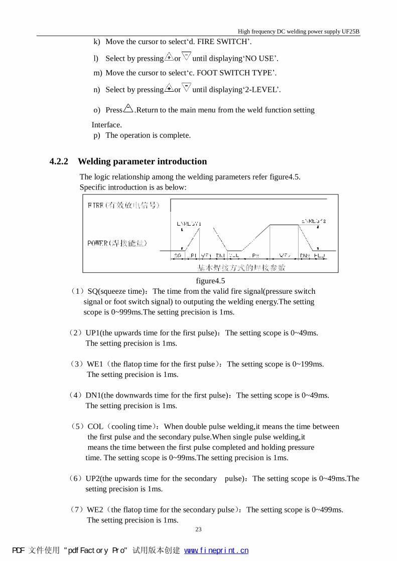
4.2.2 Welding parameter introduction The logic relationship among the welding parameters refer figure4.5. Specific introduction is as below:
figure4.5
(1)SQ(squeeze time):The time from the valid fire signal(pressure switch signal or foot switch signal) to outputing the welding energy.The setting scope is 0~999ms.The setting precision is 1ms.
(2)UP1(the upwards time for the first pulse):The setting scope is 0~49ms.
The setting precision is 1ms. (3)WE1(the flatop time for the first pulse):The setting scope is 0~199ms.
The setting precision is 1ms. (4)DN1(the downwards time for the first pulse):The setting scope is 0~49ms.
The setting precision is 1ms. (5)COL(cooling time):When double pulse welding,it means the time between
the first pulse and the secondary pulse.When single pulse welding,it means the time between the first pulse completed and holding pressure
time. The setting scope is 0~99ms.The setting precision is 1ms.
(6)UP2(the upwards time for the secondary pulse):The setting scope is 0~49ms.The setting precision is 1ms.
(7)WE2(the flatop time for the secondary pulse):The setting scope is 0~499ms.
The setting precision is 1ms.
PDF 文件使用 "pdfFactory Pro" 试用版本创建 www.fineprint.cn
High frequency DC welding power supply UF25B
24
(8)DN2(the downwards time for the secondary pulse):The setting scope is 0~49ms.The setting precision is 1ms.
(9)HLD(HOLD TIME)):The time from completing the welding energy ouput
to the pneumatic type weld head beginning left the welding point. The setting scope is 0~499ms.The setting precision is 1ms.
(10)ENREGY1(the energy of the first pulse):The parameter of the first pulse includes two parts:the control method and the capacity of the welding energy.When the output is CURRENT,the scope of the welding energy is 300A~2400A;when choose VOLTAGE,the scope is 0.3V~5.00V;When choose power,the scope is 500W~6000W.
(11)ENREGY2(the energy of the secondary pulse):The parameter of the secondary
pulse includes two parts:the control method and the capacity of the welding energy.When the output is CURRENT,the scope of the welding energy is 300A~2400A;when choose VOLTAGE,the scope is 0.3V~5.00V;When choose power,the scope is 500W~6000W.
4.2.3 Change SCH function The change SCH function is the extension for the basic welding mode.It is available for the different point welding requirements of the single workpiece.Use the pressue switch or fire switch to control the function.When using change SCH function,the criterion no will add 1 automaticly after every welding process.Use the new criterion welding parameter and monitor parameter for the next welding in order to achive different welding point using different welding parameter programme.The change SCH start from‘0’criterion and will reset to ‘0’until up to the highest criterion no that have setted. The setting steps are following: a) After boot,select‘C.OPTION SETTING’in the main menu.
b) Press to enter the welding function setting interface.
c) Move the cursor to select‘c. CHANGE SCH FEATURE’.
d) Press to light ‘ON/OFF’.
e) According to actual requirement,use or tpo start ON/OFF
this function.
f) Press to select the highest criterion beside the‘ON/OFF’.
g) According to the actual requirement,press or to change the highest criterion
no.。
h) Press to exit.
PDF 文件使用 "pdfFactory Pro" 试用版本创建 www.fineprint.cn
High frequency DC welding power supply UF25B
25
i) Press and return to the main menu from the weld function setting interface.
j) The setting is over.
4.3 ‘LINK’work mode ‘LINK’mode is suitable to match the speed welding for various welding point that have same requirement.Using this mode must assemble pneumatic type welding head and single foot switch to control welding.During the process,don’t use change SCH function.And just can set every welding criterion as single pulse.
4.3.1 Installation and setting a) Cut downthe power supply of UF25. b) Connect welding output terminal of UF25 and energy input terminal of weld
head by welding cable. c) Connect commpressed air input and compressed air source of welding
head by trachea. d) Insert the solenoid drive line of weld head into the valve drive interface back
of UF25. e) Insert the foot switch line into the foot switch input interface back of UF25. f) Turn on the power supply of UF25. g) Select‘C.OPTION SETTING’item in the main menu interface.
h) Press to enter the weld function setting interface.
i) Move the cursor to select‘f. WELD FUNCTION’.
j) Select by pressing or until displaying‘BASIC’.
k) Move the cursor to select‘d. FIRE SWITCH’.
l) Select by pressing or until displaying‘NO USE’.
m) Move the cursor to select‘c. FOOT SWITCH TYPE’.
n) Select by pressing or until displaying‘1-LEVEL’.
o) Press .Return to the main menu from the weld function setting
interface. p) The operation is complete.
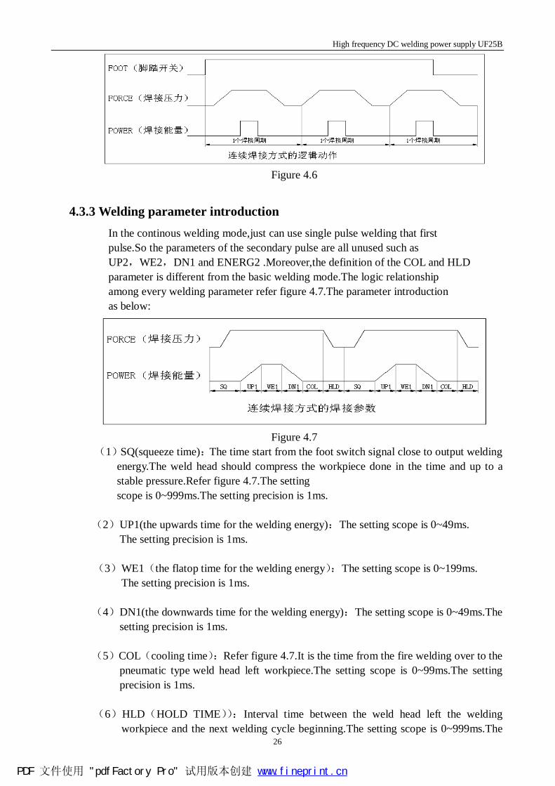
4.3.2 Welding action introduction In the continous welding mode,just can use pneumatic type weld head and Single foot switch.During the welding process,the logic action relationship of the foot
switch signal and the welding pressure refer figure 4.6.When the foot switch is valid,the welding cycle will loop continously until the foot switch open.
PDF 文件使用 "pdfFactory Pro" 试用版本创建 www.fineprint.cn
High frequency DC welding power supply UF25B
26
Figure 4.6
4.3.3 Welding parameter introduction In the continous welding mode,just can use single pulse welding that first pulse.So the parameters of the secondary pulse are all unused such as UP2,WE2,DN1 and ENERG2 .Moreover,the definition of the COL and HLD
parameter is different from the basic welding mode.The logic relationship among every welding parameter refer figure 4.7.The parameter introduction
as below:
Figure 4.7
(1)SQ(squeeze time):The time start from the foot switch signal close to output welding energy.The weld head should compress the workpiece done in the time and up to a stable pressure.Refer figure 4.7.The setting scope is 0~999ms.The setting precision is 1ms.
(2)UP1(the upwards time for the welding energy):The setting scope is 0~49ms.
The setting precision is 1ms. (3)WE1(the flatop time for the welding energy):The setting scope is 0~199ms.
The setting precision is 1ms. (4)DN1(the downwards time for the welding energy):The setting scope is 0~49ms.The
setting precision is 1ms. (5)COL(cooling time):Refer figure 4.7.It is the time from the fire welding over to the
pneumatic type weld head left workpiece.The setting scope is 0~99ms.The setting precision is 1ms.
(6)HLD(HOLD TIME)):Interval time between the weld head left the welding workpiece and the next welding cycle beginning.The setting scope is 0~999ms.The
PDF 文件使用 "pdfFactory Pro" 试用版本创建 www.fineprint.cn
High frequency DC welding power supply UF25B
27
setting precision is 1ms.
(7)ENREGY1 :The parameter of the welding energy including two parts:the control method and the capacity of the welding energy.When the output is CURRENT,the scope of the welding energy is 300A~2400A;when choose VOLTAGE,the scope is 0.3V~5.00V;When choose power,the scope is 500W~6000W.
4.4 ‘ROLL/SPOT’work mode ‘ROLL/SPOT’mode is suitable for the continous welding on the single workpiece to make a continuous weld to form a weldt.In this mode,must be used together with specially seam weld head and corresponding weld head controller.Use the pressure switch or controller of the weld head to control the discharge welding of UF25.
4.4.1 Installation and setting a) Cut downthe power supply of UF25. b) Install weld head and weld head controller(refer seam welding
head introduction). c) Insert the solenoid drive line of weld head into the valve drive interface back
of UF25. d) Insert the foot switch line into the foot switch input interface back of UF25. e) Turn on the power supply of UF25. f) Select‘C.OPTION SETTING’item in the main menu interface.
g) Press to enter the weld function setting interface.
h) Move the cursor to select‘f. WELD FUNCTION’.
i) Select by pressing or until displaying‘BASIC’.
j) Move the cursor to select‘d. FIRE SWITCH’.
k) Select by pressing or until displaying‘USE’.
l) Press .Return to the main menu from the weld function setting
Interface. m) The operation is complete.
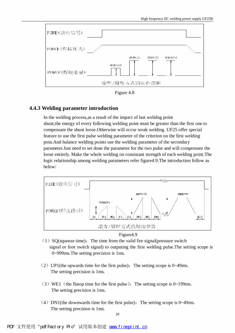
4.4.2 Welding action introduction In the‘ROLL/SPOT’mode,UF25 must be used together with the seam weld head and corresponding ‘ROLL/SPOT’weld head controller.Use the fire switch signal or pressure switch of the weld head controller to discharge.The action relationship of the weld head action,welding control signal FIRE and welding energy refer figure4.8.Due to need compensate the welding shunt phenomenon,so except the first welding point that have not sloder shunt phenomenon,all the balance welding points need to increase the welding energy to compensate the loss of welding shunt.
PDF 文件使用 "pdfFactory Pro" 试用版本创建 www.fineprint.cn
High frequency DC welding power supply UF25B
28
Figure 4.8
4.4.3 Welding parameter introduction In the welding process,as a result of the impact of last welidng point shunt,the energy of every following welding point must be greater than the first one to compensate the shunt loose.Otherwise will occur weak welding. UF25 offer special feature to use the first pulse welding parameter of the criterion on the first welding poin.And balance welding points use the welding parameter of the secondary parameter.Just need to set done the parameter for the two pulse and will compensate the loose entirely. Make the whole welding on consistant strength of each welding point.The logic relationship among welding parameters refer figure4.9.The introduction follow as below:
Figure4.9
(1)SQ(squeeze time):The time from the valid fire signal(pressure switch signal or foot switch signal) to outputing the first welding pulse.The setting scope is 0~999ms.The setting precision is 1ms.
(2)UP1(the upwards time for the first pulse):The setting scope is 0~49ms.
The setting precision is 1ms. (3)WE1(the flatop time for the first pulse):The setting scope is 0~199ms.
The setting precision is 1ms. (4)DN1(the downwards time for the first pulse):The setting scope is 0~49ms.
The setting precision is 1ms.
PDF 文件使用 "pdfFactory Pro" 试用版本创建 www.fineprint.cn
High frequency DC welding power supply UF25B
29
(5)COL(cooling time):The time between every welding point pulse. The setting scope
is 0~99ms.The setting precision is 1ms.
(6)UP2(the upwards time for the other welding point pulse):The setting scope is 0~49ms.The setting precision is 1ms.
(7)WE2(the flatop time for the other welding point pulse):The setting scope is
0~499ms.The setting precision is 1ms. (8)DN2(the downwards time for the other welding point pulse):The setting scope is
0~49ms.The setting precision is 1ms. (9)HLD(HOLD TIME)):The time that from the last welding pulse completed to the weld head left the workpiece. The setting scope is 0~999ms.The setting
precision is 1ms.
(10)ENREGY1(the energy of the first pulse):The parameter of the first pulse includes two parts:the control method and the capacity of the welding energy.When the output is CURRENT,the scope of the welding energy is 300A~2400A;when choose VOLTAGE,the scope is 0.3V~5.00V;When choose power,the scope is 500W~6000W.
(11)ENREGY2(the energy of the secondary pulse):The parameter of the secondary
pulse includes two parts:the control method and the capacity of the welding energy.When the output is CURRENT,the scope of the welding energy is 300A~2400A;when choose VOLTAGE,the scope is 0.3V~5.00V;When choose power,the scope is 500W~6000W.
4.5 ‘DOUBLE HEAD’work mode The double head mode is using one set UF25 with two sets pneumatic type weld head to
make single criterion timeshare point welding.The function effectively improve the efficiency of UF25 and reduce the investment cost. In the mode,one set UF25 must be used with two sets pneumatic type weld head. Each weld head need a pneumatic type weld head ,a fire switch and a foot switch.Both two sets weld head use the same welding criterion and timesharing weld. At the same time,just one set welding module is working working.Can use single or double pulse.
4.5.1 Installation and setting a) Cut downthe power supply of UF25. b) Connect the welding output terminal of UF25 with the energy input terminal
number A weld head by a set welding cable. c) Connect the welding output terminal of UF25 with the energy input terminal
number B weld head by another set welding cable.
PDF 文件使用 "pdfFactory Pro" 试用版本创建 www.fineprint.cn
High frequency DC welding power supply UF25B
30
d) Insert the specially welding control 3 pin line into the fire switch I/O interface back of UF25. e) Insert the pressure switch line plug of Number A weld head into the plug A of the welding control line. f) Insert the pressure switch line plug of Number B weld head into the plug B of the welding control line. g) Insert the specially foot switch connect 4 pin line into the foot switch input interface back of the UF25. h) Insert the foot switch plug of Number A weld head into the plug A of the foot switch connector. i) Insert the foot switch plug of Number B weld head into the plug B of the foot switch connector. j) Insert the specially 3 pin solenoid valve drive line into the solenoid valve drive interface back of the UF25. k) Insert the solenoid valve line plug of Number A weld head into the Number A interface of the solenoid valve line. l) Insert the solenoid valve line plug of Number B weld head into the Number B interface of the solenoid valve line. m) Connect the copressed air input interface of Number A weld head with the compressed air source by trachea. n) Connect the copressed air input interface of Number B weld head with with the compressed air source by trachea. o) Turn on the power supply of UF25. p) Select‘C.OPTION SETTING’in the main menu.
q) Press to enter the weld function setting interface.
r) Move the cursor and select‘f. WELD FUNCTION’.
s) Use or to select until displaying‘DOUBLE HEAD’.
t) Move the cursor and select‘d. FIRE SWITCH’.
u) Press or to select until displaying‘USE’.
v) Press and return to the main menu from the weld function setting interface.
w) The operation is completed.
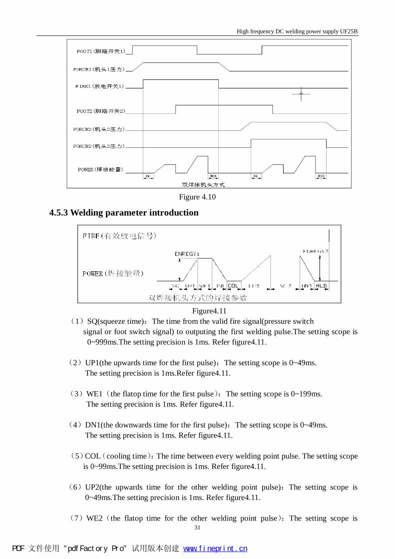
4.5.2 Welding action introduction UF25 can timesharing weld with two sets UF25 pneumatic typew weld head ,two pieces single foot switch and two pressure switch.When trample one of the foot switch,the corresponding weld head will finish the welding action,meanwhile another weld head is in a waiting state.After the last welding process completed,the next one just start.The specific logic relationship refer picutre4.10.
PDF 文件使用 "pdfFactory Pro" 试用版本创建 www.fineprint.cn
High frequency DC welding power supply UF25B
31
Figure 4.10
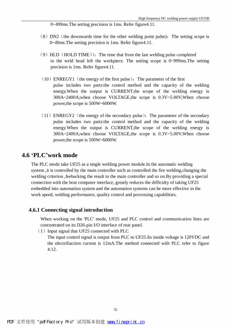
4.5.3 Welding parameter introduction
Figure4.11
(1)SQ(squeeze time):The time from the valid fire signal(pressure switch signal or foot switch signal) to outputing the first welding pulse.The setting scope is 0~999ms.The setting precision is 1ms. Refer figure4.11.
(2)UP1(the upwards time for the first pulse):The setting scope is 0~49ms.
The setting precision is 1ms.Refer figure4.11. (3)WE1(the flatop time for the first pulse):The setting scope is 0~199ms.
The setting precision is 1ms. Refer figure4.11. (4)DN1(the downwards time for the first pulse):The setting scope is 0~49ms.
The setting precision is 1ms. Refer figure4.11. (5)COL(cooling time):The time between every welding point pulse. The setting scope
is 0~99ms.The setting precision is 1ms. Refer figure4.11.
(6)UP2(the upwards time for the other welding point pulse):The setting scope is 0~49ms.The setting precision is 1ms. Refer figure4.11.
(7)WE2(the flatop time for the other welding point pulse):The setting scope is
PDF 文件使用 "pdfFactory Pro" 试用版本创建 www.fineprint.cn
High frequency DC welding power supply UF25B
32
0~499ms.The setting precision is 1ms. Refer figure4.11. (8)DN2(the downwards time for the other welding point pulse):The setting scope is
0~49ms.The setting precision is 1ms. Refer figure4.11. (9)HLD(HOLD TIME)):The time that from the last welding pulse completed to the weld head left the workpiece. The setting scope is 0~999ms.The setting
precision is 1ms. Refer figure4.11.
(10)ENREGY1(the energy of the first pulse):The parameter of the first pulse includes two parts:the control method and the capacity of the welding energy.When the output is CURRENT,the scope of the welding energy is 300A~2400A;when choose VOLTAGE,the scope is 0.3V~5.00V;When choose power,the scope is 500W~6000W.
(11)ENREGY2(the energy of the secondary pulse):The parameter of the secondary
pulse includes two parts:the control method and the capacity of the welding energy.When the output is CURRENT,the scope of the welding energy is 300A~2400A;when choose VOLTAGE,the scope is 0.3V~5.00V;When choose power,the scope is 500W~6000W.
4.6 ‘PLC’work mode The PLC mode take UF25 as a single welding power module.In the automatic welding system ,it is controlled by the main controller such as controlled the fire welding,changing the welding criterion ,feebacking the result to the main controller and so on.By providing a special connection with the host computer interface, greatly reduces the difficulty of taking UF25 embedded into automation system and the automation systems can be more effective in the work speed, welding performance, quality control and processing capabilities.
4.6.1 Connecting signal introduction When working on the 'PLC' mode, UF25 and PLC control and communication lines are concentrated on its D26-pin I/O interface of rear panel. (1)Input signal that UF25 connected with PLC The input control signal is output from PLC to UF25.Its inside voltage is 120VDC and
the electrifiaction current is 12mA.The method connected with PLC refer to figure 4.12.
PDF 文件使用 "pdfFactory Pro" 试用版本创建 www.fineprint.cn
High frequency DC welding power supply UF25B
33
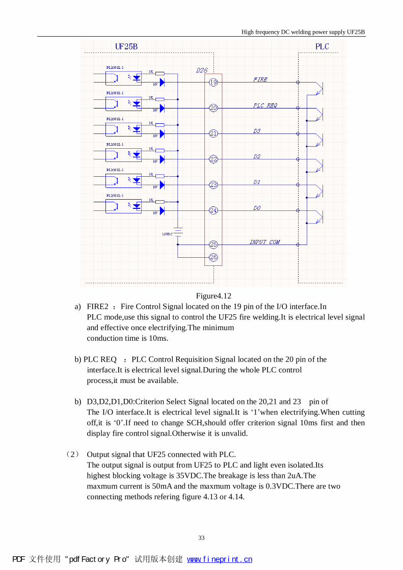
Figure4.12
a) FIRE2 :Fire Control Signal located on the 19 pin of the I/O interface.In PLC mode,use this signal to control the UF25 fire welding.It is electrical level signal and effective once electrifying.The minimum conduction time is 10ms.
b) PLC REQ :PLC Control Requisition Signal located on the 20 pin of the interface.It is electrical level signal.During the whole PLC control process,it must be available.
b) D3,D2,D1,D0:Criterion Select Signal located on the 20,21 and 23 pin of
The I/O interface.It is electrical level signal.It is ‘1’when electrifying.When cutting off,it is ‘0’.If need to change SCH,should offer criterion signal 10ms first and then display fire control signal.Otherwise it is unvalid.
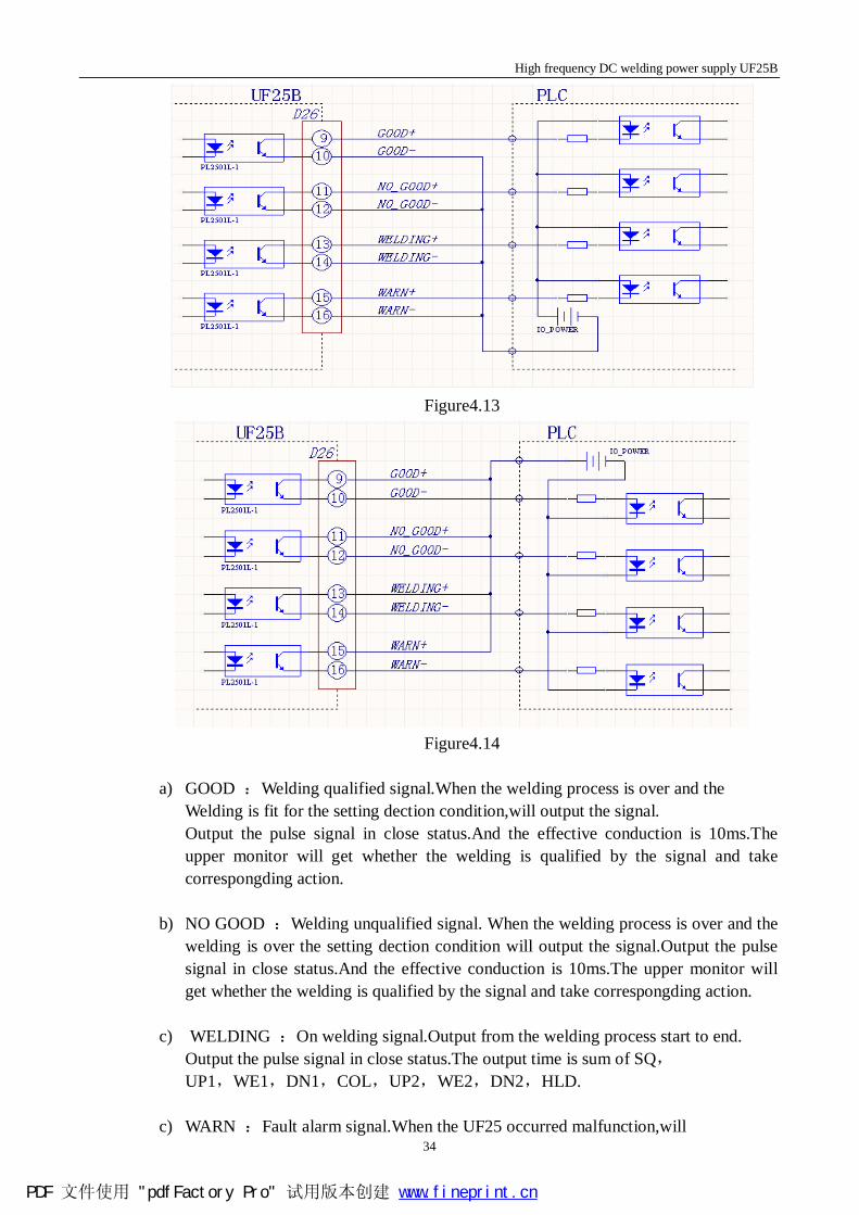
(2) Output signal that UF25 connected with PLC. The output signal is output from UF25 to PLC and light even isolated.Its highest blocking voltage is 35VDC.The breakage is less than 2uA.The maxmum current is 50mA and the maxmum voltage is 0.3VDC.There are two connecting methods refering figure 4.13 or 4.14.
PDF 文件使用 "pdfFactory Pro" 试用版本创建 www.fineprint.cn
High frequency DC welding power supply UF25B
34
Figure4.13
Figure4.14
a) GOOD :Welding qualified signal.When the welding process is over and the
Welding is fit for the setting dection condition,will output the signal. Output the pulse signal in close status.And the effective conduction is 10ms.The upper monitor will get whether the welding is qualified by the signal and take correspongding action.
b) NO GOOD :Welding unqualified signal. When the welding process is over and the welding is over the setting dection condition will output the signal.Output the pulse signal in close status.And the effective conduction is 10ms.The upper monitor will get whether the welding is qualified by the signal and take correspongding action.
c) WELDING :On welding signal.Output from the welding process start to end. Output the pulse signal in close status.The output time is sum of SQ,
UP1,WE1,DN1,COL,UP2,WE2,DN2,HLD.
c) WARN :Fault alarm signal.When the UF25 occurred malfunction,will
PDF 文件使用 "pdfFactory Pro" 试用版本创建 www.fineprint.cn
High frequency DC welding power supply UF25B
35
stop all the actions automaticly and output the signal until the fault or alarm solved.And UF25 will not accept any introduction.
4.6.2 Installation and setting a) Cut downthe power supply of the UF25. b) Use one set welding cable to connect the welding output terminal of UF25 with
energy input terminal of weld head. c) According actual demand,connect the I/O interface back of UF25 with PLC by
signal line. d) Turn on the powe supply of the UF25. e) Select‘C.OPTION SETTING’in the main menu.
f) Press to enter the weld function setting interface.
g) Move the cursor to select‘f. WELD FUNCTION’.
h) Press or to select until displaying ‘PLC’.
i) Use the to return to the main menu from the weld function setting interface.
j) The operation is complete.
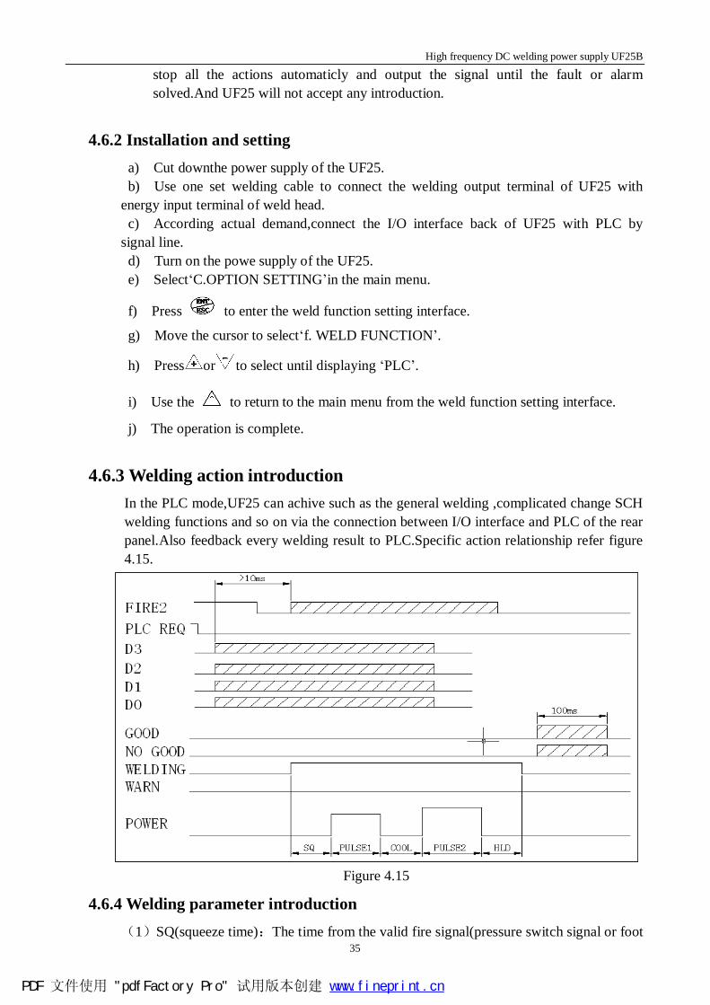
4.6.3 Welding action introduction In the PLC mode,UF25 can achive such as the general welding ,complicated change SCH welding functions and so on via the connection between I/O interface and PLC of the rear panel.Also feedback every welding result to PLC.Specific action relationship refer figure 4.15.
Figure 4.15
4.6.4 Welding parameter introduction (1)SQ(squeeze time):The time from the valid fire signal(pressure switch signal or foot
PDF 文件使用 "pdfFactory Pro" 试用版本创建 www.fineprint.cn
High frequency DC welding power supply UF25B
36
switch signal) to outputing the first welding pulse.The setting scope is 0~999ms.The setting precision is 1ms.
(2)UP1(the upwards time for the first pulse):The setting scope is 0~49ms.
The setting precision is 1ms. (3)WE1(the flatop time for the first pulse):The setting scope is 0~199ms.
The setting precision is 1ms. (4)DN1(the downwards time for the first pulse):The setting scope is 0~49ms.
The setting precision is 1ms. (5)COL(cooling time):The time between every welding point pulse. The setting scope
is 0~99ms.The setting precision is 1ms.
(6)UP2(the upwards time for the other welding point pulse):The setting scope is 0~49ms.The setting precision is 1ms.
(7)WE2(the flatop time for the other welding point pulse):The setting scope is
0~499ms.The setting precision is 1ms. (8)DN2(the downwards time for the other welding point pulse):The setting scope is
0~49ms.The setting precision is 1ms. (9)HLD(HOLD TIME)):The time that from the last welding pulse completed to the weld head left the workpiece. The setting scope is 0~999ms.The setting
precision is 1ms.
(10)ENREGY1(the energy of the first pulse):The parameter of the first pulse includes two parts:the control method and the capacity of the welding energy.When the output is CURRENT,the scope of the welding energy is 300A~2400A;when choose VOLTAGE,the scope is 0.3V~5.00V;When choose power,the scope is 500W~6000W.
(11)ENREGY2(the energy of the secondary pulse):The parameter of the secondary
pulse includes two parts:the control method and the capacity of the welding energy.When the output is CURRENT,the scope of the welding energy is 300A~2400A;when choose VOLTAGE,the scope is 0.3V~5.00V;When choose power,the scope is 500W~6000W.
PDF 文件使用 "pdfFactory Pro" 试用版本创建 www.fineprint.cn