Embed Size (px)
Citation preview
ARL-RP-0555 SEP 2015
US Army Research Laboratory
High Fidelity Simulation of Atomization in Diesel Engine Sprays by L Bravo, CB Ivey, D Kim, and ST Bose Reprinted from Center for Turbulence Research. [accessed 2015 Sep 14]. https://ctr.stanford .edu/proceedings-2014-summer-program. Proceedings of the 2014 Center for Turbulence Research Summer Program; 2014 Aug 26; Stanford, CA. Approved for public release; distribution is unlimited.

NOTICES
Disclaimers The findings in this report are not to be construed as an official Department of the Army position unless so designated by other authorized documents. Citation of manufacturer’s or trade names does not constitute an official endorsement or approval of the use thereof. Destroy this report when it is no longer needed. Do not return it to the originator.
ARL-RP-0555 SEP 2015
US Army Research Laboratory
High Fidelity Simulation of Atomization in Diesel Engine Sprays by L Bravo Vehicle Technology Directorate, ARL CB Ivey Center for Turbulence Research, Stanford University, Stanford, CA D Kim and ST Bose Cascade Technologies, Inc, Palo Alto, CA Reprinted from Center for Turbulence Research. [accessed 2015 Sep 14]. https://ctr.stanford.edu /proceedings-2014-summer-program. Proceedings of the 2014 Center for Turbulence Research Summer Program; 2014 August 26; Stanford, CA. Approved for public release; distribution is unlimited.
ii
REPORT DOCUMENTATION PAGE Form Approved OMB No. 0704-0188
Public reporting burden for this collection of information is estimated to average 1 hour per response, including the time for reviewing instructions, searching existing data sources, gathering and maintaining the data needed, and completing and reviewing the collection information. Send comments regarding this burden estimate or any other aspect of this collection of information, including suggestions for reducing the burden, to Department of Defense, Washington Headquarters Services, Directorate for Information Operations and Reports (0704-0188), 1215 Jefferson Davis Highway, Suite 1204, Arlington, VA 22202-4302. Respondents should be aware that notwithstanding any other provision of law, no person shall be subject to any penalty for failing to comply with a collection of information if it does not display a currently valid OMB control number. PLEASE DO NOT RETURN YOUR FORM TO THE ABOVE ADDRESS.
1. REPORT DATE (DD-MM-YYYY)
September 2015 2. REPORT TYPE
Reprint 3. DATES COVERED (From - To)
January 2014–September 2014 4. TITLE AND SUBTITLE
High Fidelity Simulation of Atomization in Diesel Engine Sprays 5a. CONTRACT NUMBER
5b. GRANT NUMBER
5c. PROGRAM ELEMENT NUMBER
6. AUTHOR(S)
L Bravo, CB Ivey, D Kim, and ST Bose 5d. PROJECT NUMBER
5e. TASK NUMBER 5f. WORK UNIT NUMBER
7. PERFORMING ORGANIZATION NAME(S) AND ADDRESS(ES)
US Army Research Laboratory ATTN: RDRL-VTP Aberdeen Proving Ground, MD 21005-5066
8. PERFORMING ORGANIZATION REPORT NUMBER
ARL-RP-0555
9. SPONSORING/MONITORING AGENCY NAME(S) AND ADDRESS(ES)
10. SPONSOR/MONITOR'S ACRONYM(S)
11. SPONSOR/MONITOR'S REPORT NUMBER(S)
12. DISTRIBUTION/AVAILABILITY STATEMENT
Approved for public release; distribution is unlimited. 13. SUPPLEMENTARY NOTES Reprinted from Center for Turbulence Research. [accessed 2015 Sep 14]. https://ctr.stanford.edu/proceedings-2014-summer -program. Proceedings of the 2014 Center for Turbulence Research Summer Program; 2014 August 26; Stanford, CA 14. ABSTRACT
A high fidelity numerical simulation of jet breakup and spray formation from a complex diesel fuel injector has been performed. A full understanding of the primary atomization process of diesel fuel injection has not been achieved for several reasons, including the difficulties in accessing the optically dense region. Due to recent advances in numerical methods and computing resources, high fidelity simulations of realistic atomizing flows are currently feasible, providing a new mechanism to study the jet breakdown process. In the present study, a novel volume-of-fluid (VOF) method coupled to a stochastic Lagrangian spray (LSP) model is employed to simulate the atomization process. A common rail fuel injector is modeled by a nozzle geometry provided by the engine combustion network (ECN). The working conditions correspond to a single 90 μm orifice JP-8 fueled injector operating at 90 bar and 373 K and releasing into a 100% nitrogen, 29 bar, 300 K ambient with a Rel = 16, 071 and Wel = 75, 334, putting the spray in the full atomization mode. The experimental dataset from Army Research Lab (ARL) is used for validation and the Kelvin-Helmholtz/Rayleigh-Taylor (KH-RT) breakup model (Reitz & Bracco 1979) is used for verification, both in terms of spray angle. Droplet distributions of the simulated spray are provided for future experimental comparisons and secondary atomization simulations using LSP modeling. 15. SUBJECT TERMS
turbulence, sprays, volume of fluids, CFD, diesel 16. SECURITY CLASSIFICATION OF:
17. LIMITATION OF ABSTRACT
UU
18. NUMBER OF PAGES
16
19a. NAME OF RESPONSIBLE PERSON
L Bravo a. REPORT
Unclassified b. ABSTRACT
Unclassified c. THIS PAGE
Unclassified 19b. TELEPHONE NUMBER (Include area code)
410-278-9525 Standard Form 298 (Rev. 8/98)
Prescribed by ANSI Std. Z39.18
Center for Turbulence ResearchProceedings of the Summer Program 2014
1
High fidelity simulation of atomization in dieselengine sprays
By L. Bravo†, C. B. Ivey, D. Kim‡, AND S. T. Bose‡
A high fidelity numerical simulation of jet breakup and spray formation from a complexdiesel fuel injector has been performed. A full understanding of the primary atomizationprocess of diesel fuel injection has not been achieved for several reasons, including thedifficulties in accessing the optically dense region. Due to recent advances in numericalmethods and computing resources, high fidelity simulations of realistic atomizing flowsare currently feasible, providing a new mechanism to study the jet breakdown process.In the present study, a novel volume-of-fluid (VOF) method coupled to a stochastic La-grangian spray (LSP) model is employed to simulate the atomization process. A commonrail fuel injector is modeled by a nozzle geometry provided by the engine combustion net-work (ECN). The working conditions correspond to a single 90 µm orifice JP-8 fueledinjector operating at 90 bar and 373 K and releasing into a 100% nitrogen, 29 bar, 300K ambient with a Rel = 16, 071 and Wel = 75, 334, putting the spray in the full at-omization mode. The experimental dataset from Army Research Lab (ARL) is used forvalidation and the Kelvin-Helmholtz/Rayleigh-Taylor (KH-RT) breakup model (Reitz &Bracco 1979) is used for verification, both in terms of spray angle. Droplet distributionsof the simulated spray are provided for future experimental comparisons and secondaryatomization simulations using LSP modeling.
1. Introduction
To date, one of the main bottlenecks in engineering spray modeling of combustionsystems is an accurate description of the primary atomization process. Several contem-porary numerical solvers adopt coarse approximations in the dense region based on in-jecting nozzle-sized particles subject to Kelvin-Helmholtz type instabilities coupled withLagrangian particle tracking techniques (Som & Aggarwal 2009; Senecal 2012). Signif-icant success has been achieved with these methods; however, they require a posterioriknowledge of the spray process to calibrate the model, making an a priori investiga-tion impossible. Historically, the advancement of primary atomization models has beenhindered by the well-known difficulties in measuring the optically dense spray region. Al-though experimentalists have had success with modern methods, such as ballistic imagingand x-ray techniques, extraction of full four dimensional information with sufficient spa-tial and temporal resolution for a detailed analysis is still infeasible (Linne et al. 2006;Wang et al. 2006; Coletti et al. 2014).
Remarkable progress has been made in recent years in the development of robust nu-merical methods for handling interfaces, enabling researchers to perform highly resolvedsimulations of multiphase flow (Gorokhovski & Herrmann 2008). Desjardins reportedon the development of the level set/ghost fluid method utilizing high order schemes to
† Vehicle Technology Directorate, Army Research Laboratory‡ Cascade Technologies, Inc.
2 Bravo et al.
study multiphase flows (Desjardins et al. 2008). The accuracy of the numerical techniquewas corroborated through several studies, including the atomization of a liquid dieseljet at moderately low Reynolds number, Re = 3000. In a related study, Desjardins con-ducted detailed numerical simulations (DNS) of primary atomization for several values ofReynolds and Weber numbers (2000 < Re < 3000, 500 < We < 2000), reporting on ve-locity statistics across the turbulent jet (Desjardins & Pitsch 2010). More recently, usinga refined level set grid approach, Herrmann discussed the impact of finite grid resolu-tion on the phase interface geometry of the liquid jet core under diesel engine conditionswith Re = 5000 and an injection velocity of 100 m/s (Herrmann 2011). In this work, itwas reported that turbulence is the driving mechanism of atomization within the first20 diameters downstream of the injector. It was also determined that 6 grid points areneeded to obtain grid-independence of larger scale drops. These studies provide a criti-cal database to drive the next-generation spray model development. Note that, as withmost other DNS studies, no quantitative comparison to experimental data is typicallyprovided.
The need to accurately model two phase atomizing flows in high speed jets is partic-ularly important in diesel injectors where the quality of the fuel and oxidizer mixing isessential for lean combustion. Fuel/air mixture formation is also a very important factorin increasing engine efficiencies and power densities. Spray and atomization characteris-tics have to be considered to optimize the design of the combustion chamber to reduceexhaust emissions and to improve combustion performance. Also, diesel spray charac-teristics can be influenced by the injector geometry, the injection parameters, and theflow mixing inside the combustion chamber. Therefore, simulations should account forsystem level complexities, including real injector features to accurately predict realisticspray dynamics.
Additionally, the computational expense of resolving all the critical length scales atlarge Weber number is prohibitively large, so the application of DNS to simulate realisticdiesel injector conditions has been severely limited. A liquid jet moving with an O(100)m/s relative velocity with respect to the quiescent gas can generate droplets with diam-eters as a small as a few microns (Desjardins & Pitsch 2010). Hence, there is a need todevelop more accurate engineering breakup spray models for the primary and secondarybreakup modes to reduce the computational cost when simulating a spray filled domain.
The objective of the current work is to investigate the atomization behavior of ahigh-speed single hole jet with complex internal geometry. A novel unstructured volume-of-fluid (VOF) method has been adopted, which is geometric and un-split, enforcingexact mass conservation on an unstructured grid (Kim et al. 2013, 2014). In this study,the VOF method is coupled to the Lagrangian spray (LSP) framework to increase thecomputational efficiency and to apply sub-grid atomization models. Hence, the phaseinterface resolved by the grid is captured by the VOF method, while the under resolvedsmall scale droplets are transferred from the VOF interface representation to the LSPparticle tracking and further breakup is handled by a stochastic breakup model. Mea-surements were conducted at the Spray and Combustion Research Facility of the ArmyResearch Lab (ARL) to qualitatively complement the simulation and to validate the sim-ulation in terms spray angle. The Kelvin-Helmholtz/Rayleigh-Taylor (KH-RT) breakupmodel (Reitz & Bracco 1979) is used to verify the simulation in terms of spray angle.Droplet distributions were generated for future experimental comparisons and secondaryatomization models.

Atomization in diesel engine sprays 3
2. Methods
2.1. Simulation
The detailed numerical simulation of the interface was performed using a novel geometricunsplit VOF method that is conservative on unstructured meshes coupled to a stochasticLagrangian spray (LSP) framework. The geometric VOF method ensures discrete con-servation and boundedness of the volume fraction, F , by utilizing non-overlapping fluxpolyhedra for donor volumes (see Ivey & Moin 2012 for a description of flux polyhedra).The volume-of-fluid method uses piecewise linear interface calculation (PLIC) represen-tation of the interface, requiring an interface normal, n. n is calculated from an auxiliarylevel set, G, that was updated using the geometric advection algorithm to keep it consis-tent with F . Curvature, κ is also calculated from the G using the direct front curvature
method (Herrmann 2006). After n and κ are calculated, G is reconstructed to strictlyfollow the PLIC representation using a bisection algorithm to calculate the local G field(to enforce F ) and the reconstructed distance function (Cummins et al. 2005) methodto propagate the G field throughout the band. For consistency (and stability), mass andmomentum are convected using the geometric VOF method. To diminish the strict over-flow time step requirements on VOF schemes, multiple frozen velocity advection updates(taken as 3 here) are performed for each momentum step. Several validation studies havebeen performed that tested the numerical accuracy and robustness of the solver (Kimet al. 2013, 2014).
For computational efficiency, the VOF representation is coupled to a stochastic La-grangian spray (LSP) representation. Interfacial features are characterized by contiguousregions of F > 0. Under resolved (taken < 53 cells here) interfacial flow structures are re-placed by a spherical droplet of equal volume. No additional breakup model is employedhere so as to capture the instabilities leading to atomization directly. LSP droplets fol-low particle drag laws and a stochastic breakup model based on critical Webber number(Ham et al. 2003).
The simulation was conducted on the nozzle geometry available through the engineercombustion network (ECN) with flow conditions corresponding to an injection pressureof 90 bar, a background pressure of 20 bar, and a bulk jet exit velocity of 127 m/s. TheReynolds and Weber number were calculated with JP-8 fuel properties database (at 373K) and yielded a value of Rel = 16, 071 and Wel = 75, 334. The critical length scales,determined from the problem configuration, range from the nozzle orifice integral scale(li = d = 90 µm), to the viscous scale (0.09 µm), and down to Kolmogorov critical radius(0.2 µm). The pipe flow viscous scale and the critical radius are defined as,
lv = 1/0.2Re−7/8 and lcr =(
σ3
ρ3ǫ2
)1/5
. (2.1)
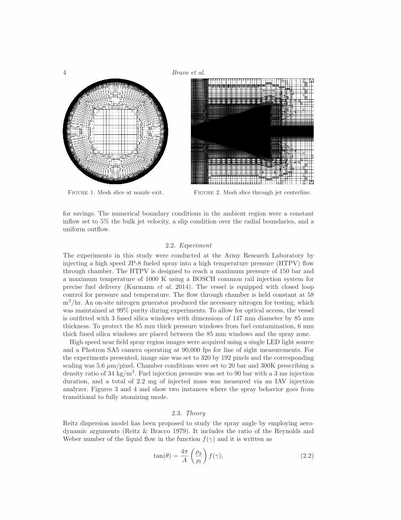
A large eddy simulation dynamic Smagorinsky model was adopted to treat the smallestflow structures and for computational efficiency. In the nozzle, a wall resolved approachwas utilized with ∆x+,∆y+ ∼ 1 near the wall (calculated from lv), ∆x+,∆y+ ∼ 50 nearthe center, and ∆z+ ∼ 70 (see Figure 1). The mesh refinement is cartesian in nature,forcing ∆x = ∆y = ∆r. A mesh of ∼ 60 million hexahedral control volumes was used todiscretize the domain. Mesh points were concentrated in the jet spray envelope to resolvethe interface, while coarse buffer regions were added in the radial and axial regions inorder to reduce the impact of the boundary conditions (see Figure 2). Within the sprayenvelope, ∆/lcr ∼ 0.5 near the unperturbed nominal interface to capture the instabilitiesand ∆/lcr ∼ 40 throughout the rest of the spray envelope to leverage the LSP framework
4 Bravo et al.
Figure 1. Mesh slice at nozzle exit. Figure 2. Mesh slice through jet centerline.
for savings. The numerical boundary conditions in the ambient region were a constantinflow set to 5% the bulk jet velocity, a slip condition over the radial boundaries, and auniform outflow.
2.2. Experiment
The experiments in this study were conducted at the Army Research Laboratory byinjecting a high speed JP-8 fueled spray into a high temperature pressure (HTPV) flowthrough chamber. The HTPV is designed to reach a maximum pressure of 150 bar anda maximum temperature of 1000 K using a BOSCH common rail injection system forprecise fuel delivery (Kurmann et al. 2014). The vessel is equipped with closed loopcontrol for pressure and temperature. The flow through chamber is held constant at 58m3/hr. An on-site nitrogen generator produced the necessary nitrogen for testing, whichwas maintained at 99% purity during experiments. To allow for optical access, the vesselis outfitted with 3 fused silica windows with dimensions of 147 mm diameter by 85 mmthickness. To protect the 85 mm thick pressure windows from fuel contamination, 6 mmthick fused silica windows are placed between the 85 mm windows and the spray zone.
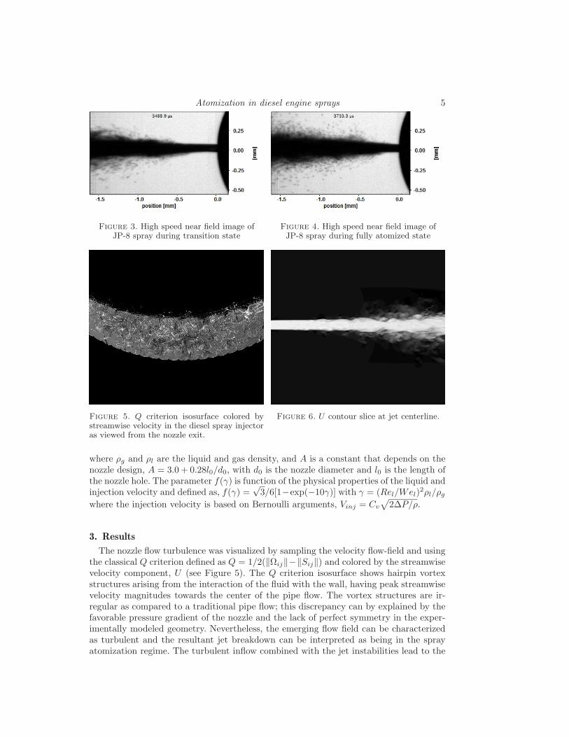
High speed near field spray region images were acquired using a single LED light sourceand a Photron SA5 camera operating at 90,000 fps for line of sight measurements. Forthe experiments presented, image size was set to 320 by 192 pixels and the correspondingscaling was 5.6 µm/pixel. Chamber conditions were set to 20 bar and 300K prescribing adensity ratio of 34 kg/m3. Fuel injection pressure was set to 90 bar with a 3 ms injectionduration, and a total of 2.2 mg of injected mass was measured via an IAV injectionanalyzer. Figures 3 and 4 and show two instances where the spray behavior goes fromtransitional to fully atomizing mode.
2.3. Theory
Reitz dispersion model has been proposed to study the spray angle by employing aero-dynamic arguments (Reitz & Bracco 1979). It includes the ratio of the Reynolds andWeber number of the liquid flow in the function f(γ) and it is written as
tan(θ) =4π
A
(
ρg
ρl
)
f(γ), (2.2)
Atomization in diesel engine sprays 5
Figure 3. High speed near field image ofJP-8 spray during transition state
Figure 4. High speed near field image ofJP-8 spray during fully atomized state
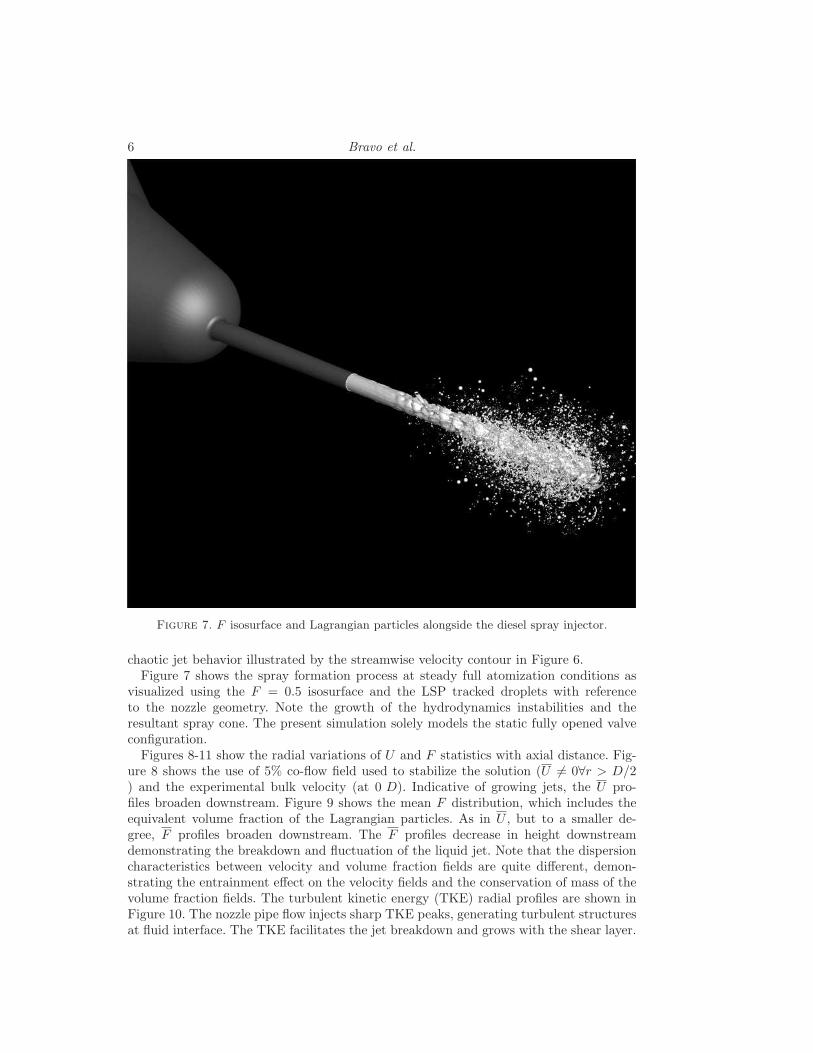
Figure 5. Q criterion isosurface colored bystreamwise velocity in the diesel spray injectoras viewed from the nozzle exit.
Figure 6. U contour slice at jet centerline.
where ρg and ρl are the liquid and gas density, and A is a constant that depends on thenozzle design, A = 3.0 + 0.28l0/d0, with d0 is the nozzle diameter and l0 is the length ofthe nozzle hole. The parameter f(γ) is function of the physical properties of the liquid andinjection velocity and defined as, f(γ) =
√3/6[1−exp(−10γ)] with γ = (Rel/Wel)
2ρl/ρg
where the injection velocity is based on Bernoulli arguments, Vinj = Cv
√
2∆P/ρ.
3. Results
The nozzle flow turbulence was visualized by sampling the velocity flow-field and usingthe classical Q criterion defined as Q = 1/2(‖Ωij‖−‖Sij‖) and colored by the streamwisevelocity component, U (see Figure 5). The Q criterion isosurface shows hairpin vortexstructures arising from the interaction of the fluid with the wall, having peak streamwisevelocity magnitudes towards the center of the pipe flow. The vortex structures are ir-regular as compared to a traditional pipe flow; this discrepancy can by explained by thefavorable pressure gradient of the nozzle and the lack of perfect symmetry in the exper-imentally modeled geometry. Nevertheless, the emerging flow field can be characterizedas turbulent and the resultant jet breakdown can be interpreted as being in the sprayatomization regime. The turbulent inflow combined with the jet instabilities lead to the
6 Bravo et al.
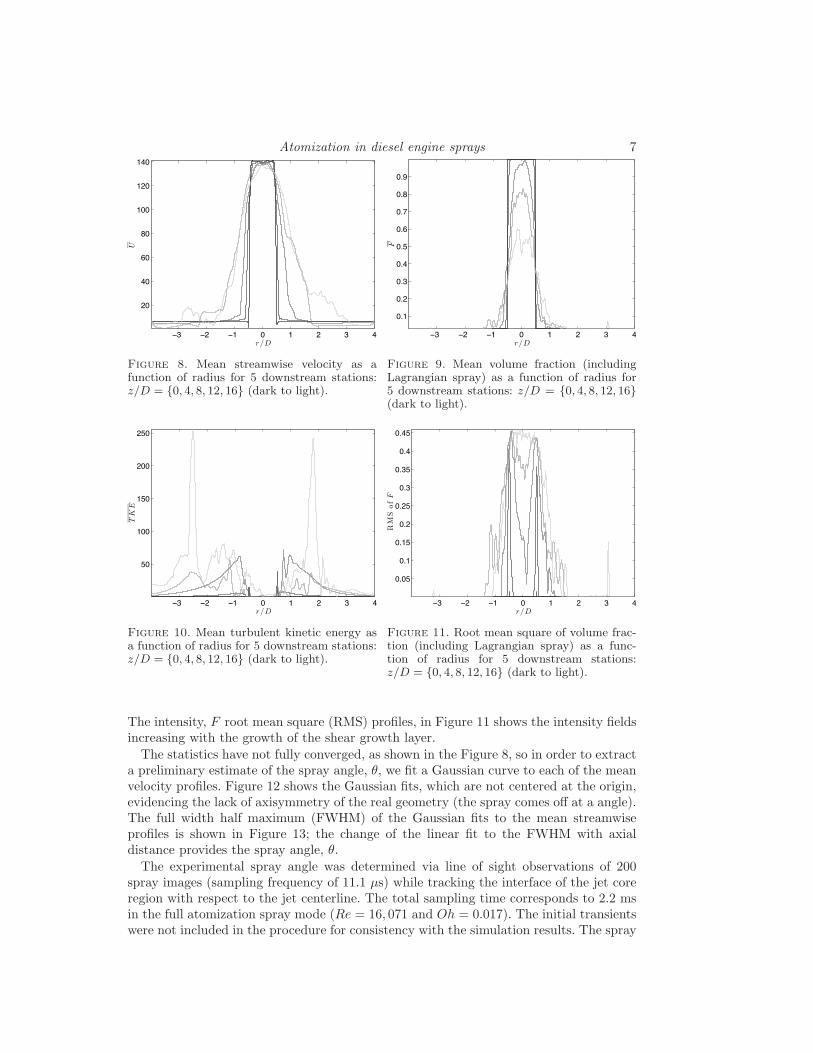
Figure 7. F isosurface and Lagrangian particles alongside the diesel spray injector.
chaotic jet behavior illustrated by the streamwise velocity contour in Figure 6.Figure 7 shows the spray formation process at steady full atomization conditions as
visualized using the F = 0.5 isosurface and the LSP tracked droplets with referenceto the nozzle geometry. Note the growth of the hydrodynamics instabilities and theresultant spray cone. The present simulation solely models the static fully opened valveconfiguration.
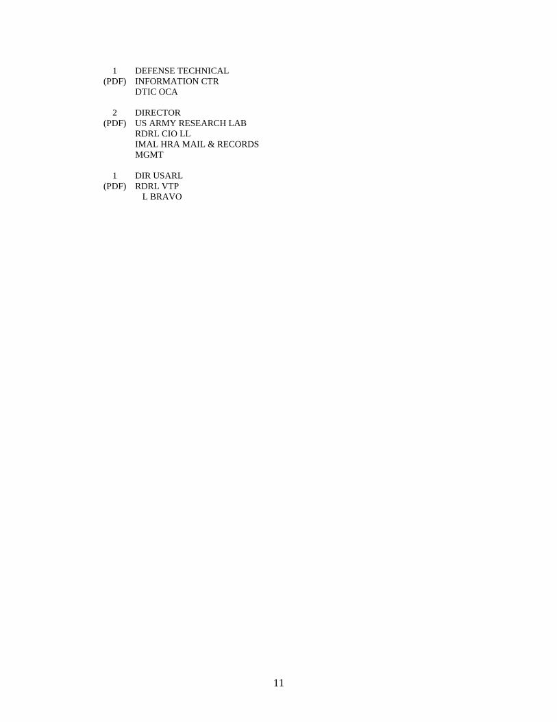
Figures 8-11 show the radial variations of U and F statistics with axial distance. Fig-ure 8 shows the use of 5% co-flow field used to stabilize the solution (U 6= 0∀r > D/2) and the experimental bulk velocity (at 0 D). Indicative of growing jets, the U pro-files broaden downstream. Figure 9 shows the mean F distribution, which includes theequivalent volume fraction of the Lagrangian particles. As in U , but to a smaller de-gree, F profiles broaden downstream. The F profiles decrease in height downstreamdemonstrating the breakdown and fluctuation of the liquid jet. Note that the dispersioncharacteristics between velocity and volume fraction fields are quite different, demon-strating the entrainment effect on the velocity fields and the conservation of mass of thevolume fraction fields. The turbulent kinetic energy (TKE) radial profiles are shown inFigure 10. The nozzle pipe flow injects sharp TKE peaks, generating turbulent structuresat fluid interface. The TKE facilitates the jet breakdown and grows with the shear layer.
Atomization in diesel engine sprays 7
ï! ï" ï# $ # " ! %
"$
%$
&$
'$
#$$
#"$
#%$
r/D
U
Figure 8. Mean streamwise velocity as afunction of radius for 5 downstream stations:z/D = 0, 4, 8, 12, 16 (dark to light).
ï! ï" ï# $ # " ! %
$&#
$&"
$&!
$&%
$&'
$&(
$&)
$&*
$&+
r/D
F
Figure 9. Mean volume fraction (includingLagrangian spray) as a function of radius for5 downstream stations: z/D = 0, 4, 8, 12, 16(dark to light).
ï! ï" ï# $ # " ! %
&$
#$$
#&$
"$$
"&$
r/D
TKE
Figure 10. Mean turbulent kinetic energy asa function of radius for 5 downstream stations:z/D = 0, 4, 8, 12, 16 (dark to light).
ï! ï" ï# $ # " ! %
$&$'
$&#
$&#'
$&"
$&"'
$&!
$&!'
$&%
$&%'
r/D
RMSofF
Figure 11. Root mean square of volume frac-tion (including Lagrangian spray) as a func-tion of radius for 5 downstream stations:z/D = 0, 4, 8, 12, 16 (dark to light).
The intensity, F root mean square (RMS) profiles, in Figure 11 shows the intensity fieldsincreasing with the growth of the shear growth layer.
The statistics have not fully converged, as shown in the Figure 8, so in order to extracta preliminary estimate of the spray angle, θ, we fit a Gaussian curve to each of the meanvelocity profiles. Figure 12 shows the Gaussian fits, which are not centered at the origin,evidencing the lack of axisymmetry of the real geometry (the spray comes off at a angle).The full width half maximum (FWHM) of the Gaussian fits to the mean streamwiseprofiles is shown in Figure 13; the change of the linear fit to the FWHM with axialdistance provides the spray angle, θ.
The experimental spray angle was determined via line of sight observations of 200spray images (sampling frequency of 11.1 µs) while tracking the interface of the jet coreregion with respect to the jet centerline. The total sampling time corresponds to 2.2 msin the full atomization spray mode (Re = 16, 071 and Oh = 0.017). The initial transientswere not included in the procedure for consistency with the simulation results. The spray

8 Bravo et al.
ï! ï" ï# $ # " ! %
"$
%$
&$
'$
#$$
#"$
#%$
#&$
r/D
GaussianFitofU
Figure 12. Gaussian fit to mean streamwisevelocity as a function of radius for 5 down-stream stations: z/D = 0, 4, 8, 12, 16 (darkto light).
0 5 10 15
0.8
1
1.2
1.4
1.6
1.8
2
z/D
FW
HM
ofG
auss
ian
Fit
of
UFigure 13. Full width half maximum of gaus-sian fit to mean stream wise velocity as a func-tion of downstream location. θ is the angleof linear fit to the full width half maximum(shown in gray).
angles extracted from Reitz theory, simulation, and experiment are respectively
θReitz = 5.8325 , θsim = 5.1125 and θexp ∼ 4. (3.1)
The simulation and theoretical dispersion results appear to be in good agreement.However, there is a 1 discrepancy with the experiments featuring a spray angle of 4.The differences can be in part due to variations in the nozzle orifice diameter and nozzleshape that arise from manufacturer fabrication eccentricities. This has been reported inthe literature previously for ECN type injectors where geometric inconsistencies werethoroughly reported (Kastengran et al. 2012). The impact of these discrepancies canclearly affect the spray parameters.
Secondary atomization models require an initial droplet spray profile, parameterizedby droplet diameter and distance away from jet. Droplet sizes and counts are calculatedfrom the combination of the LSP particles and the resolved VOF features (calculatedusing the same method to transfer from VOF to LSP for under resolved features, butwith a larger domain cell count). Figure 14 shows the average number of droplets for agiven droplet diameter. The droplets range from approximately 1 − 10 µm, the averagedroplet diameter is 2.9786 µm, and the most likely droplet diameter is 1.5055 µm. Dropletdiameters < 1 µm were spontaneously evaporated and were not tracked. Figure 15 showsthe average droplet diameter at a given distance away from the jet center. The averagedroplet size increases away from the jet going from approximately 2 − 7 µm.
4. Conclusions
In this investigation a high fidelity simulation approach was adopted to study the atom-ization physics of a diesel injector with detailed nozzle internal geometry. The nozzle flowfield was characterized through visualizations of Q isosurfaces for turbulence patterns.The complexity of the geometry and system dynamics was characterized by a snapshot ofthe volume fraction isosurface and Lagrangian droplets. Also, mean streamwise velocityand volume fraction statistics show the structure of the high speed jet. The turbulent

Atomization in diesel engine sprays 9
!"# $ $"# % %"#
&'$!ï#
!
$!!!
%!!!
(!!!
)!!!
#!!!
*!!!
+!!!
,!!!
-!!!
Dp
Np
Figure 14. Number of droplets as a functionof diameter
!"# $ $"# % %"# & &"# ' '"#
()$!ï'
!
$
%
&
'
#
*
+
,
-()$!
ï*
r
Dp(r
)Figure 15. Mean droplet diameter as a
function of radius
kinetic energy and volume fraction inensitity profiles characterize the interfacial mixingprocesses. Comparison with Reitz spray theory and ARL measurements of the near noz-zle flow field show that the simulation captures the correct dispersion characteristics.The spray was further characterized using droplet size and spatial distribution plots.Further work is presently on the way, using higher resolution to establish numerical con-vergence and to capture the hydrodynamic flow instabilities for comparison with classicalinstability models.
Acknowledgments
The authors acknowledge the following award for providing computing, visualizationresources that have contributed to the research results reported within this report: MRI-R2: Acquisition of a Hybrid CPU/GPU and Visualization Cluster for MultidisciplinaryStudies in Transport Physics with Uncertainty Quantification (http://www.nsf.gov/awardsearch/showAward.do?AwardNumber=0960306). This award is funded under theAmerican Recovery and Reinvestment Act of 2009 (Public Law 111-5).
An award of computer time was provided by the Innovative and Novel ComputationalImpact on Theory and Experiment (INCITE) program. This research used resources ofthe Argonne Leadership Computing Facility at Argonne National Laboratory, which issupported by the Office of Science of the U.S. Department of Energy under contractDE-AC02-06CH11357.
This research was supported in part by an appointment to the U.S. Army ResearchLaboratory Postdoctoral Fellowship Program administered by the Oak Ridge AssociatedUniversities through a contract with ARL.
REFERENCES
Coletti, F., Benson, M. J., Sagues, A. L., Miller, B. H., Fahrig, R. & Eaton,
J. K. 2014 Three-dimensional mass fraction distribution of a spray measured byx-ray computed tomography. Journal of Engineering for Gas Turbines and Power
136 (5), 051508.
Cummins, S. J., Francois, M. M. & Kothe, D. B. 2005 Estimating curvature fromvolume fractions. Computers & Structures 83 (6–7), 425 – 434.

10 Bravo et al.
Desjardins, O., Moureau, V. & Pitsch, H. 2008 An accurate conservative levelset/ghost fluid method for simulating turbulent atomization. Journal of Compua-
tional Physics 227 (18), 8395–8416.
Desjardins, O. & Pitsch, H. 2010 Detailed numerical investigation of turbulent at-omization of liquid jets. Atomization and Sprays 20 (4), 311–336.
Gorokhovski, M. & Herrmann, M. 2008 Modeling primary atomization. Annual
Review of Fluid Mechanics 40 (1), 343–366.
Ham, F., Apte, S., Iaccarino, G., Wu, X., Herrmann, M., Constantinescu,
G., Mahesh, K. & Moin, P. 2003 Unstructured les of reacting multiphase flows inrealistic gas turbine combustors. Center for Turbulence Research Annual Research
Briefs pp. 139–160.
Herrmann, M. 2006 A balanced force refined level set grid method for two-phase flowson unstructured flow solver grids. Center for Turbulence Research Annual Research
Briefs pp. 167–184.
Herrmann, M. 2011 On simulating primary atomization using the refined level set gridmethod. Atomization and Sprays 21 (4), 283–301.
Ivey, C. B. & Moin, P. 2012 Conservative volume of fluid advection method on unstruc-tured grids in three dimensions. Center for Turbulence Research Annual Research
Briefs pp. 179–192.
Kastengran, A. L., Tilocco, F. Z., Duke, D. J., Manin, J., Pickett, L. M.,
Payri, R. & Bazyn, T. 2012 Engine combustion network (ecn): measurements ofnozzle geometry and hydraulic behavior. Atomization and Sprays 22 (12), 1011–1052.
Kim, D., Ham, F., Bose, S., Le, H., Herrmann, M., Li, X., Soteriou, C. &
Kim, W. 2014 High fidelity atomization in a gas turbine injector high shear nozzle.In Institute for Liquid Atomization and Spray Systems, 26th Annual Conference.Portland, Oregon.
Kim, D., Mani, A. & Moin, P. 2013 Numerical simulation of bubble formation bybreaking waves in turbulent two-phase couette flow. Center for Turbulence Research
Annual Research Briefs .
Kurmann, M., Bravo, L., Kweon, C. B. & Tess, M. 2014 The effect of fuel injectornozzle configuration on jp-8 sprays at diesel engine conditions. In Institute for Liquid
Atomization and Spray Systems, 26th Annual Conference. Portland, Oregon.
Linne, M., Paciaroni, M., Hall, T. & Parker, T. 2006 Ballistic imaging of thenear field in a diesel spray. Experiments in Fluids 40 (6), 836–846.
Reitz, R. D. & Bracco, F. B. 1979 On the dependence of spray angle and otherspray parameters on nozzle design and operating conditions. SAE Technical Paper
p. 790494.
Senecal, P. 2012 Grid convergent spray models for internal combustion engine cfd sim-ulations. In Proceedings fo the ASME 2012 ICE Division Fall Technical Conference.
Som, S. & Aggarwal, S. K. 2009 Assessment of atomization models for diesel enginesimulations. Atomization and Sprays 19 (9), 885–903.
Wang, Y. J., Im, K. S., Fezzaa, K., Lee, W. K., Wang, J., Micheli, P. & Laub,
C. 2006 Quantitative x-ray phase contrast imaging of air-assisted water sprays withhigh weber numbers. Applied Physics Letters 89 (15), 151913.
11
1 DEFENSE TECHNICAL (PDF) INFORMATION CTR DTIC OCA 2 DIRECTOR (PDF) US ARMY RESEARCH LAB RDRL CIO LL IMAL HRA MAIL & RECORDS MGMT 1 DIR USARL (PDF) RDRL VTP L BRAVO

12
INTENTIONALLY LEFT BLANK