Embed Size (px)
Citation preview

TPS22915B
TPD6F003 TPD2EUSB30
TPD1E10B06
TPS22915B
SN74LVC1G126
DSP Board
SDRAM
Speaker for Audio Output
SD Card with Pre-loaded DSP Firmware
SN74LVC1G126SN74LVC1G126
TAS2557
I2C/I2S
5 V
3.3 V_A
1.8 V
BBB_5V
RESET
I2C/I2S
GPIO
USB_BUS
I2S
I2S
To MIC Board
D+/D-
3.3 V_D
1.8 V
Micro USB Connector
5 V
TPS22912C12.288 MHz
TMS320C5517
TPS386000
TPS65023
TPS3850
%HDJOH%RQH�
Black Wireless(BBB-W)
MIC Board
TLV320ADC3101
MICBIAS1
MICBIAS2
BBB_5V
SPI
1.3 V1.4 V1.8 V
3.3 V_A
3. 3 V_D
1TIDUE77–October 2018Submit Documentation Feedback
Copyright © 2018, Texas Instruments Incorporated
High Fidelity, Near-Field Two-Way Audio Reference Design With NoiseReduction and Echo Cancellation
TI Designs: TIDA-01589High Fidelity, Near-Field Two-Way Audio ReferenceDesign With Noise Reduction and Echo Cancellation
DescriptionMan machine interaction requires an acoustic interfacefor providing full duplex hands-free communication. Inhands-free mode, part of the far-end or near-end audiosignal from the speaker is coupled to the microphones.Furthermore, in noisy environments the microphonesalso capture ambient noise in addition to the usefulnear-end audio signal. The captured multi-microphoneaudio signals are corrupted by acoustic backgroundnoise as well as by echoic signals that significantlydegrade the intelligibility of the desired signal, andrestrict the performance of subsequent audioprocessing systems. This reference designdemonstrates dual microphones for audio input viastereo ADC, low-power DSP performing noisereduction, acoustic echo cancellation, and other audioquality enhancement algorithms. This design alsofeatures TI’s Smart Amp technology for high-qualityand high-SPL audio output from a micro-speaker.
Resources
TIDA-01589 Design FolderTPS65023 Product FolderTLV320ADC3101 Product FolderTPS386000 Product FolderTPS3850 Product FolderTMS320C5517 Product FolderTAS2557 Product Folder
ASK Our E2E™ Experts
Features• Two-way audio modular platform supporting analog
or digital microphone for audio capture andplayback on micro-speaker using TI Smart Amptechnology
• TLV320ADC3101 Stereo ADC with 92-dBA SNR,0.003% THD integrated PGA, AGC, and mini-DSPfor implementing decimation filtering
• Powerful TMS320C5517 DSP for implementingvarious audio-processing algorithms like: AdaptiveSpectral Noise Reduction (ASNR) and AcousticEcho Cancellation (AEC) handling echo tails up-to128 ms
• Smart Amp TAS2557 with integrated ultra-low-noise audio DAC, class-D power amplifier andbuilt-in speaker sensing and protection to deliverhigh SPL using micro-speaker
• Attaches to AM335x-based BeagleBone™ BlackWireless to support optional Cloud connectivity
Applications• Video Doorbell• Thermostat• IP Network Camera• Wi-Fi® Camera• Smart Home Alarm Systems

System Description www.ti.com
2 TIDUE77–October 2018Submit Documentation Feedback
Copyright © 2018, Texas Instruments Incorporated
High Fidelity, Near-Field Two-Way Audio Reference Design With NoiseReduction and Echo Cancellation
An IMPORTANT NOTICE at the end of this TI reference design addresses authorized use, intellectual property matters and otherimportant disclaimers and information.
1 System DescriptionAudio as Human Machine Interface (HMI) is an emerging trend in many building automation end-equipment such as IP network camera, Wi-Fi security camera, video doorbell, thermostat, smoke detector,intercom panel, smart speaker, audio and video conferencing systems, and others. The whole idea ofhaving audio in smart home devices is to provide full duplex hands-free communication making the userexperience more simple, comfortable, and reliable. The ability of the system to extract clear speech oraudio from a noisy environment is important to applications that use voice activation and speechrecognition. Particularly, hands-free systems implementing voice-activation and speech recognition alsoincorporate an audio playback path. This represents another challenge to voice recognition systems, as itadds other noise components. The realization of a hands-free communication system requires solutions toseveral fundamental challenges:• Noise reduction: Handling background noise to extract clear audio• Echo cancellation: Ensuring that there is no echo under any usage condition• De-reverberation: Ensuring consistent performance even during changes to echo path• Ensuring a full-duplex performance during double talk• Limited on-chip resources to process audio data and running several algorithms to improve system
performance• Real-time processing of captured audio data along with additional features like voice activation and
speech recognition• Higher sound pressure level (SPL) using micro-speaker and speaker protection
There are various ways that audio artifacts can be introduced to the system degrading the quality ofcaptured audio. Ambient noise in the environment picked up by the microphones can create problems thatcorrupt the audio signal being transmitted and heard on the other end. Signal processing techniques suchas adaptive spectral noise reduction (ASNR) and automatic gain control (AGC) are used to improveoverall system performance ensuring high fidelity communication. ASNR helps to reduce background andbroadband noise with a minimal reduction in signal quality and automatic gain control (AGC) helps toboost lower level speech signals in hands-free environments. Spectral noise reduction uses the frequencydomain to effectively remove ambient and unwanted noise components from an audio signal, making iteasier to hear the desired signal. Using adaptive filtering techniques creates an estimate of the signal’snoise component. This noise component, when subtracted from the composite signal, reveals the bestpossible representation of the actual speech signal.
Acoustic echo occurs when the audio being played back is picked up directly or indirectly by themicrophones and fed back in to the system. It can be exacerbated when the audio playback volume ishigh or the speaker and microphones are in close proximity. While some of the echo can be mitigated bykeeping distance between the microphone and speaker however, this might not be possible in small spaceconstrained systems. A more robust answer is to use acoustic echo cancellation (AEC) algorithms. Inbrief, an AEC samples audio from the far side as it comes in and compares it to audio from captured bymicrophones. If any of the audio matches, the AEC removes it by creating adaptive filters to prevent effectof echo in real time. A critical attribute of the acoustic echo cancellation is its ability to quickly detect thetime variances and the reflected audio signals and adapt to a changing environment while minimizing anyaudio distortion. In real-life, this could be introduced by a participant who is moving while speaking or is ina dynamic environment that might have changing attributes like a door opening and closing. Figure 1shows the effect of how echo and reverberation complicate the capture of a clean voice signal at themicrophone.

www.ti.com System Description
3TIDUE77–October 2018Submit Documentation Feedback
Copyright © 2018, Texas Instruments Incorporated
High Fidelity, Near-Field Two-Way Audio Reference Design With NoiseReduction and Echo Cancellation
Figure 1. Effect of Echo and Reverberation When Speaker and Microphone Elements are in CloseProximity
Protecting the speaker requires controlling the voice-coil temperature and keeping the cone/diaphragmexcursion within safe limits. Conventional hardware-based speaker protection matches the continuouspower output of the audio amplifier with the speaker output rating and sometimes incorporates high passfiltering to prevent over-excursion. Unfortunately, imposing a hard limit on speaker output suppressesaudio peaks and also reduces clarity. A more sophisticated approach uses an in-depth understanding ofspeaker behavior to protect it from failure while simultaneously increasing loudness and preserving audioquality. PurePath™ Smart Amp technology replaces hardware-based speaker protection methods withpredictive algorithms, speaker characterization tools and real-time signal monitoring to increase the peakoutput of the speaker without damage. IV Sense amplifiers or Smart Amps from Texas Instruments™ buildupon the classic Class-D audio amplifier by adding the ability to monitor the temperature and excursion ofthe speaker in real time. This is controlled by an algorithm running in the DSP inside the device. Thisfeedback allows the device to monitor the health of the speaker and optimize the sound quality to enablegreat audio.
TIDA-01589 features multi-microphone capable advanced audio processing algorithms from AdaptiveDigital Technologies running on C5517 DSP such as beamforming, adaptive spectral noise reduction,acoustic echo cancellation, anti-howling, adaptive filtering, nonlinear processing, and double talk detectionto produce a high-quality, full-duplex communication. This design also provides a scalable platform forimplementing new features like voice activation, speech recognition and directional of arrival (DOA) ofsound. TI has a suite of silicon and third party based software algorithms, from the analog front end toprocessed speech output that you can integrate into a complete yet efficient solution for a givenapplication.

System Description www.ti.com
4 TIDUE77–October 2018Submit Documentation Feedback
Copyright © 2018, Texas Instruments Incorporated
High Fidelity, Near-Field Two-Way Audio Reference Design With NoiseReduction and Echo Cancellation
1.1 Key System Specifications
Table 1. Key System Specifications
PARAMETERS SPECIFICATIONS DetailsMicrophone Number of microphones : Two Section 2.3.2.1
Type of microphone : AnalogICS-40618: High dynamic range microphone with differential output and lowpower
Boot image DSP board boot image - Contact Adaptive Digital for Boot image C5517 Boot ImageExplained in Section 2.3.3
BeagleBone Black wireless boot image - Contact Adaptive Digital for Boot image Section 2.3.5Speaker SPS0916B-J-01 mounted on DSP board Section 2.3.4.1Code ComposerStudio version
Code Composer Studio 8
External InterfacesInput voltage(VDD_5V)
Input DC voltage (4.5V to 5.5V, Typical 5V) Section 2.3.1
JTAG 7 × 2 male header J7 on DSP board JTAG Interface inSection 2.3.3
MIC boardconnector
Male header J1 on DSP board
BeagleBonecape connectors
Male headers J4 and J5 to connect BeagleBone Black wireless
Speakerconnector
Terminal connector (J15) to connect speaker terminals

TPS22915B
TPD6F003 TPD2EUSB30
TPD1E10B06
TPS22915B
SN74LVC1G126
DSP Board
SDRAM
Speaker for Audio Output
SD Card with Pre-loaded DSP Firmware
SN74LVC1G126SN74LVC1G126
TAS2557
I2C/I2S
5 V
3.3 V_A
1.8 V
BBB_5V
RESET
I2C/I2S
GPIO
USB_BUS
I2S
I2S
To MIC Board
D+/D-
3.3 V_D
1.8 V
Micro USB Connector
5 V
TPS22912C12.288 MHz
TMS320C5517
TPS386000
TPS65023
TPS3850
%HDJOH%RQH�
Black Wireless(BBB-W)
MIC Board
TLV320ADC3101
MICBIAS1
MICBIAS2
BBB_5V
SPI
1.3 V1.4 V1.8 V
3.3 V_A
3. 3 V_D
www.ti.com System Overview
5TIDUE77–October 2018Submit Documentation Feedback
Copyright © 2018, Texas Instruments Incorporated
High Fidelity, Near-Field Two-Way Audio Reference Design With NoiseReduction and Echo Cancellation
2 System Overview
2.1 Block Diagram
Figure 2. TIDA-01589 Block Diagram
2.2 Highlighted Products
2.2.1 TPS65023 - Power Management IC (PMIC) With 3 DC/DCs, 3 LDOs, I2C Interface and DVSTPS65023x has 5 regulator channels, 3 DC/DCs and 2 LDOs. DCDC3 has dynamic voltage scalingfeature (DVS) that allows for power reduction to CORE supplies during idle operation or overvoltageduring heavy-duty operation. With DVS and 2 more DC/DCs plus 2 LDOs, the TPS65023x is ideal forCORE, Memory, IO, and peripheral power for the entire system.
For noise-sensitive circuits, the DC/DCs can be synchronized out of phase from one another, reducing thepeak noise at the switching frequency. Each converter can be forced to operate in PWM mode to ensureconstant switching frequency across the entire load range. However, for low load efficiency performancethe DC/DCs automatically enter PSM mode which reduces the switching frequency when the load currentis low, saving power at idle operation.
2.2.2 TLV320ADC3101 - Low-Power Stereo ADC With Embedded miniDSP for Wireless Handsets andPortable Audio
TLV320ADC3101 is a flexible, low-power, stereo audio ADC device with extensive feature integrationsupporting sampling rates from 8 kHz to 96 kHz and has provision for both analog and PDM microphonesinput. Audio data is transferred between the host processor and the TLV320ADC3101 via the digital-audioserial-data interface, or audio bus.
2.2.3 TPS386000 - Quad Supply Voltage Supervisors With Adjustable Delay and Watchdog TimerThe TPS3860x0 multi-channel supervisory family of devices combines four complete SVS function setsinto one IC, along with a watchdog timer, a window comparator, and negative voltage sensing.TPS386000 is used to monitor voltage rails powering C5517 DSP.

System Overview www.ti.com
6 TIDUE77–October 2018Submit Documentation Feedback
Copyright © 2018, Texas Instruments Incorporated
High Fidelity, Near-Field Two-Way Audio Reference Design With NoiseReduction and Echo Cancellation
2.2.4 TPS3850 - Precision Voltage Supervisor With Window Watchdog Timer and Programmable DelayThe TPS3850 is a high-accuracy voltage supervisor with an integrated watchdog timer. It is used tomonitor voltage rail powering C5517 DSP.
2.2.5 TMS320C5517- Fixed-Point Digital Signal ProcessorTMS320C5517 is a member of TI's C5000™ fixed-point Digital Signal Processor (DSP) product family andis designed for low active and standby power consumption. It is used to process audio data coming fromstereo ADC and perform audio quality enhancement algorithms like Adaptive Spectral Noise Reduction(ASNR) , Acoustic Echo Cancellation (AEC) and Beamforming (BF).
2.2.6 TAS2557 - 5.7-W Class-D Mono Audio Amplifier with Class-H Boost and Speaker SenseThe TAS2557 device is a state-of-the-art Class-D audio amplifier which is a full system on a chip (SoC).The device features a ultra low-noise audio DAC and Class-D power amplifier which incorporates speakervoltage and current sensing feedback. An on-chip, low-latency DSP supports Texas Instruments' SmartAmp speaker protection algorithms to maximize loudness while maintaining safe speaker conditions.
2.2.7 TPS22915- 5.5-V, 2-A, 38-mΩ Load Switch With Quick Output DischargeTPS22915 is a 5.5-V, 2-A load switch in a 4-pin YFP package. To reduce voltage drop for low voltage andhigh current rails, the device implements an ultra-low resistance N-channel MOSFET which reduces thedrop out voltage through the device. It is used for power sequencing in this design.
2.2.8 TPS22912C- Ultra-small, Low On Resistance Load Switch With Controlled Turn-onTPS22912C is single channel, 2-A load switches in ultra-small, space saving 4-pin WCSP package. Thesedevices implement a low resistance P-channel MOSFET with a controlled rise time for applications thatneed to limit the inrush current and has Full time reverse current protection. It is used to powerBeagleBone from DSP board.
2.2.9 SN74LVC1G126- Single Bus Buffer Gate With 3-State OutputsThe SN74LVC1G126 device contains a dual buffer gate with output enable control and performs theBoolean function Y = A
2.2.10 TPD6F003- 6-Channel EMI Filter for Display InterfaceThe TPDxF003 family is a series of highly integrated devices designed to provide EMI filtering in allsystems subjected to electromagnetic interference. These filters also provide a Transient VoltageSuppressor (TVS) diode circuit for ESD protection which prevents damage to the application whensubjected to ESD stress far exceeding IEC 61000-4-2 (Level 4).
2.2.11 TPD2EUSB30- 2-Channel ESD Solution for SuperSpeed USB 3.0 InterfaceThe TPD2EUSB30, TPD2EUSB30A, and TPD4EUSB30 are 2 and 4 channel Transient VoltageSuppressor (TVS) based Electrostatic Discharge (ESD) protection diode arrays. The TPDxEUSB30/Adevices are rated to dissipate ESD strikes at the maximum contact level specified in the IEC 61000-4-2international standard (Contact). These devices also offer 5 A (8/20 μs) peak pulse current ratings per IEC61000-4-5 (surge) specification.
2.2.12 TPD1E10B06- Single-Channel ESD in 0402 Package With 10-pF Capacitance and 6-V BreakdownThe TPD1E10B06 is a single-channel ESD TVS diode in a small 0402 package. This TVS protectionproduct offers ±30-kV IEC air-gap, ±30-kV contact ESD protection, and has an ESD clamp circuit with aback-to-back TVS diode for bipolar or bidirectional signal support. The 12-pF line capacitance of this ESDprotection diode is suitable for a wide range of applications supporting data rates up to 400 Mbps.

%HDJOH%RQH�
Black Wireless(BBB-W)
Acoustic Echo Canceller
Noise Reduction
Pre-AEC Digital Gain
Post AEC Digital Gain
Digital GainI2S2RX Out
TMS320C5517
MSS
ExternalMemory
I2S0
BF 18°
BF 36°
BF 54°
BF 72°
Near-side Talker
Far-side Talker
- Adaptive Digital VQE Software
DSP Board
TAS2557
I2S3
MIC Board
TLV320ADC3101
Speaker for Audio Output
xx
x
x x
x
www.ti.com System Overview
7TIDUE77–October 2018Submit Documentation Feedback
Copyright © 2018, Texas Instruments Incorporated
High Fidelity, Near-Field Two-Way Audio Reference Design With NoiseReduction and Echo Cancellation
2.3 System Design TheoryThis section explains the design theory for the key devices used in the design. The TIDA-01589demonstration setup highlights modular architecture with three boards:• DSP board with Power management, TMS320C5517 DSP, TAS2557 Smart Amp, and micro-speaker• MIC board with two microphones and TLV320ADC3101 stereo ADC• BeagleBone black wireless (BBB-W)
TIDA-01589 features the High-Definition Acoustic Echo Canceller (HD AEC™) from Adaptive DigitalTechnologies which is multi-microphone capable and includes beamforming, noise reduction, anti-howling,adaptive filtering, nonlinear processing, and double talk detection to produce a high-quality, full-duplexreal-time communication between two participants.
Figure 3 shows a diagram with the signal flow for this application. The “near side” participant’s voice isinput through the 2-mic array on MIC board and sampled at 16-kHz (wideband) rate by theTLV320ADC3101 low-power stereo ADC. Digital PCM audio samples are passed from the audio ADC tothe TMS320C5517 DSP over I2S where beamforming (BF) is performed and the HD AEC™ is running.Processed (clean) audio samples from DSP are passed as PCM data over I2S to the BeagleBone BlackWireless (BBB-W). BBB-W is used to tie in the “far side” participant and provides audio playback overUSB to a headset attached to it. A microphone in the headset of the far-side participant will take voiceinput and pass it via BBB-W to the DSP over I2S interface.
The DSP application provides a clean audio signal to TAS2557 over I2S which drives micro-speakerattached to the DSP board. TAS2557 features an ultra-low noise digital-to-analog converter (DAC) andClass-D power amplifier with speaker voltage and current sensing feedback. An on-chip DSP providesspeaker protection algorithms, tuned to the micro-speaker for maximizing audio output while maintainingsafe speaker operation.
Figure 3. HD AEC™ Signal Flow on TIDA-01589 Hardware
2.3.1 Power ManagementThe input power to TIDA-01589 is provided by connecting a DC adapter of 5 V, with 6.5-A current ratingthrough the DC Jack (J10) available on the DSP board. All the required power rails are generated from theTPS65023 PMIC which has 3 DC/DCs and 2 LDOs integrated. Figure 4 shows power tree for TIDA-01589:
TLV320ADC3101
%HDJOH%RQH�
Black Wireless(BBB-W)
AS4C32M16MS-7BCNSDRAM
SN74LVC1G126
12.288-MHz Oscillator
TPS22915B
TPS65023
TPS22915B TMS320C5517
TAS2557
SN74LVC1G126SN74LVC1G126
5-V DC Input
5-A Fuse
DSP Board
MIC Board
Universal 5-V DC Adapter
TPS386000
TPS3850
Micro USB Connector
TPS22912C
1.5-A Fuse
CPU_3V3_USB
USB_LDO_OUT_1V3
VCCD_3V3
VCC_CORE_1V4
VCC_1V8VCC_1V3
VCCA_3V3
VDD_5V0_BBB
VDD_5V
MICBIAS1
MICBIAS2
S
S
System Overview www.ti.com
8 TIDUE77–October 2018Submit Documentation Feedback
Copyright © 2018, Texas Instruments Incorporated
High Fidelity, Near-Field Two-Way Audio Reference Design With NoiseReduction and Echo Cancellation
Figure 4. TIDA-01589 Power Tree
NOTE: The BeagleBone Black Wireless (BBB-W) gets power from the TIDA-01589 DSP board sothere is no need to connect a DC adapter to BBB-W. The TPS22912C load switch with fulltime reverse current blocking powers the BBB-W with 5-V DC input from the DSP board.
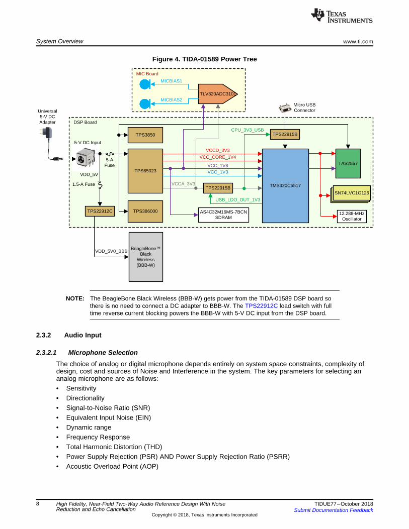
2.3.2 Audio Input
2.3.2.1 Microphone SelectionThe choice of analog or digital microphone depends entirely on system space constraints, complexity ofdesign, cost and sources of Noise and Interference in the system. The key parameters for selecting ananalog microphone are as follows:• Sensitivity• Directionality• Signal-to-Noise Ratio (SNR)• Equivalent Input Noise (EIN)• Dynamic range• Frequency Response• Total Harmonic Distortion (THD)• Power Supply Rejection (PSR) AND Power Supply Rejection Ratio (PSRR)• Acoustic Overload Point (AOP)
www.ti.com System Overview
9TIDUE77–October 2018Submit Documentation Feedback
Copyright © 2018, Texas Instruments Incorporated
High Fidelity, Near-Field Two-Way Audio Reference Design With NoiseReduction and Echo Cancellation
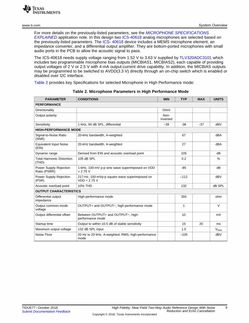
For more details on the previously-listed parameters, see the MICROPHONE SPECIFICATIONSEXPLAINED application note. In this design two ICS-40618 analog microphones are selected based onthe previously-listed parameters. The ICS- 40618 device includes a MEMS microphone element, animpedance converter, and a differential output amplifier. They are bottom-ported microphones with smallaudio ports in the PCB to allow the acoustic signal to pass.
The ICS-40618 needs supply voltage ranging from 1.52 V to 3.63 V supplied by TLV320ADC3101 whichincludes two programmable microphone bias outputs (MICBIAS1, MICBIAS2), each capable of providingoutput voltages of 2 V or 2.5 V with 4-mA output-current drive capability. In addition, the MICBIAS outputsmay be programmed to be switched to AVDD(3.3 V) directly through an on-chip switch which is enabled ordisabled over I2C interface.
Table 2 provides key Specifications for selected Microphone in High Performance mode:
Table 2. Microphone Parameters in High Performance Mode
PARAMETER CONDITIONS MIN TYP MAX UNITSPERFORMANCEDirectionality OmniOutput polarity Non-
InvertedSensitivity 1 kHz, 94 dB SPL, differential –39 -38 –37 dBVHIGH-PERFORMANCE MODESignal-to-Noise Ratio(SNR)
20-kHz bandwidth, A-weighted 67 dBA
Equivalent Input Noise(EIN)
20-kHz bandwidth, A-weighted 27 dBA
Dynamic range Derived from EIN and acoustic overload point 105 dBTotal Harmonic Distortion(THD)
105 dB SPL 0.2 %
Power Supply RejectionRatio (PSRR)
1-kHz, 100-mV p-p sine wave superimposed on VDD= 2.75 V
-85 dB
Power Supply Rejection(PSR)
217-Hz, 100-mVp-p square wave superimposed onVDD = 2.75 V
–112 dBV
Acoustic overload point 10% THD 132 dB SPLOUTPUT CHARACTERISTICSDifferential outputimpedance
High-performance mode 355 ohm
Output common-modevoltage
OUTPUT+ and OUTPUT−, high-performance mode 1 V
Output differential offset Between OUTPUT+ and OUTPUT−, high-performance mode
10 mV
Startup time Output to within ±0.5 dB of stable sensitivity 15 20 msMaximum output voltage 132 dB SPL input 1.0 VRMS
Noise Floor 20 Hz to 20 kHz, A-weighted, RMS, high-performancemode
–105 dBV

System Overview www.ti.com
10 TIDUE77–October 2018Submit Documentation Feedback
Copyright © 2018, Texas Instruments Incorporated
High Fidelity, Near-Field Two-Way Audio Reference Design With NoiseReduction and Echo Cancellation
Two analog microphones are mounted at a distance of 21.25 mm in a linear geometry on the MIC boardas Figure 5 shows.
Figure 5. MIC Board
2.3.2.2 Stereo ADC - TLV320ADC3101The TLV320ADC3101 device samples the captured audio signal from microphones and streams the digitalvalues to TMS320C5517 DSP over I2S interface. The MIC board gets power and ground from the DSPboard. The TLV320ADC3101 device consists of the following blocks:• Stereo audio multi-bit delta-sigma ADC (8 kHz–96 kHz)• Programmable digital audio effects processing (3-D, bass, treble, mid-range, EQ, de-emphasis)• Register-configurable combinations of up to six single-ended or three differential audio inputs• Fully programmable PLL with extensive ADC clock-source and divider options for maximum end-
system design flexibility
Figure 6 shows the TLV320ADC3101 functional block diagram:

Analog Signal Input
Switching and
Attenuation
AGC
PGA0 to 40 dB
0.5-dBSteps
ADC
DIN
L
DIN
R
Digital Microphone
Interface
AGC
PGA0 to 40 dB
0.5-dBSteps
ADC
mini DSP Processing
Blocks
I2C TDM Serial Bus
Interface
DOUT
BCLK
WCLK
DMCLK/GPIO2
DMDIN/GPIO1
IN1L(P)
IN2L(P)
IN3L(M)
IN1R(M)
IN2R(P)
IN3R(M)
Current Bias/Reference
Mic Bias 1
Mic Bias 2
Audio Clock Generation PLL
I2C Serial Control Bus
I2C_ADR1
I2C_ADR0
SD
A
SC
L
RE
SE
T
MC
LK
MIC
BIA
S2
MIC
BIA
S1
DV
SS
IOV
DD
DV
DD
AV
SS
AV
DD
www.ti.com System Overview
11TIDUE77–October 2018Submit Documentation Feedback
Copyright © 2018, Texas Instruments Incorporated
High Fidelity, Near-Field Two-Way Audio Reference Design With NoiseReduction and Echo Cancellation
Figure 6. TLV320ADC3101 Block Diagram
In this design, TLV320ADC3101 initializes with following configuration settings after reset state:• Control Interface: I2C Interface with C5517 DSP
– Configured as I2C slave and TMS320C5517 DSP as Master– I2C address for TLV320ADC3101: 0x18h– I2C interface supports both standard and fast communication modes
• Source reference clock: 12.288 MHz– Internally generated using integrated PLL– This reference clock is used to generate Internal ADC Clocks.
• Internal PLL Powered up• ADC sampling frequency: 16 kHz• Audio Interface: I2S interface with TMS320C5517 DSP
– Configured as I2S slave and TAS2557 Smart Amp as Master as default setting– BCLK: 1.024 MHz– WCLK: 16 kHz– I2S word length: 24 bits
• MICBIAS1 and MICBIAS2 Outputs: 2.5 V– High Performance mode for ICS-40618
• Selected Processing Block: PRB_R1
2.3.3 Audio Processing - TMS320C5517The C5517 DSP-based processor supports the real-time processing necessary along with the scalabilitydesirable for voice triggering and related products. Figure 7 shows the functional block diagram of thedevice.

DSP System
JTAG Interface
PLL/Clock Generator
Power Management
Pin Multiplexing
C55x DSP CPU
FFT Hardware Accelerator
64 KB DARAM
256 KB SARAM
128 KB ROM
Input Clocks
Switched Central Resource (SCR)
Peripherals
DMA (x4)
I2S(x3)
I2C SPI McBSP McSPI UART10-Bit
SAR ADC
USB 2.0 PHY (HS)(Device)
UHPINAND, NOR,
SRAM, mSDRAM
MMC/SD(x2)
RTCGP Timer
(x2)GP Timer
or WDLDOs
Connectivity Program/ Data Storage System
App-SpecSerial InterfacesInterconnect
System Overview www.ti.com
12 TIDUE77–October 2018Submit Documentation Feedback
Copyright © 2018, Texas Instruments Incorporated
High Fidelity, Near-Field Two-Way Audio Reference Design With NoiseReduction and Echo Cancellation
Figure 7. TMS320C5517 Block diagram
The device includes four core voltage-level supplies (CVDD, CVDDRTC, USB_VDD1P3, USB_VDDA1P3),and several I/O supplies including—DVDDIO, DVDDEMIF, DVDDRTC, USB_VDDOSC, andUSB_VDDA3P3. Figure 8 highlights the set of peripherals available on the C5517 DSP used in this designand their I/O Power supplies:
TMS320C5517
TPS65023
DCDC1
DCDC2
VDDPLL
VDDOSC
VDDA3P3
Oscillator
Reset, JTAG
I2S
SD
I2C
SPI
LCD
VDDA_PLL
CVDDRTC
DVDDEMIF
CVDD
DCDC3
LDO1
LDO2
USB2.0USB CORE
McBSP
McSPI
UHPI
GPIOVDD1P3
VDDA1P3
PMIC Voltage SourcesIntegrated LDOs in DSP
Input DC Voltage from 5V Adapter
Core & I/O SuppliesPeripherals
DVDDIO
DVDDRTC
VDDA_ANA
RTC I/O
DSP CORE
EMIF
SAR ADC
SYSTEM PLL
RTC Core
5 V
1.3 V
3.3 V
1.8 V
1.4 V
3.3 V
DSP_LDOO
USB_LDOO
ANA_LDO
www.ti.com System Overview
13TIDUE77–October 2018Submit Documentation Feedback
Copyright © 2018, Texas Instruments Incorporated
High Fidelity, Near-Field Two-Way Audio Reference Design With NoiseReduction and Echo Cancellation
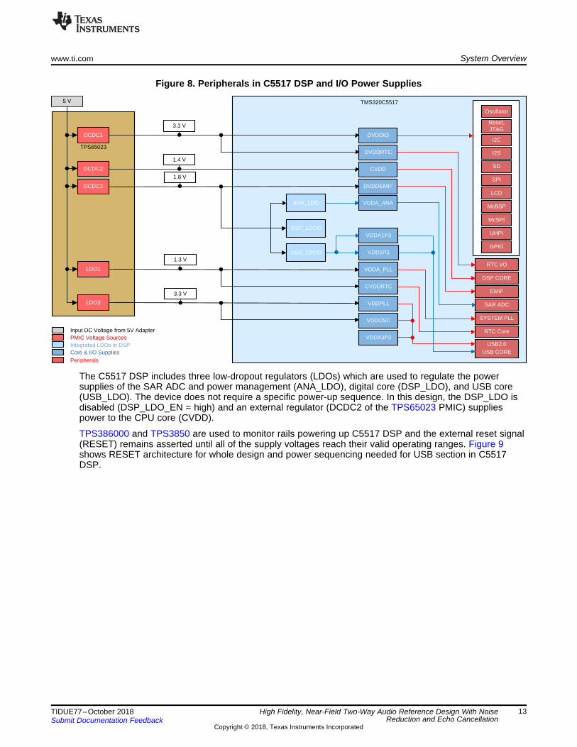
Figure 8. Peripherals in C5517 DSP and I/O Power Supplies
The C5517 DSP includes three low-dropout regulators (LDOs) which are used to regulate the powersupplies of the SAR ADC and power management (ANA_LDO), digital core (DSP_LDO), and USB core(USB_LDO). The device does not require a specific power-up sequence. In this design, the DSP_LDO isdisabled (DSP_LDO_EN = high) and an external regulator (DCDC2 of the TPS65023 PMIC) suppliespower to the CPU core (CVDD).
TPS386000 and TPS3850 are used to monitor rails powering up C5517 DSP and the external reset signal(RESET) remains asserted until all of the supply voltages reach their valid operating ranges. Figure 9shows RESET architecture for whole design and power sequencing needed for USB section in C5517DSP.

TPS386000
TPS3850
TPS22915B
5-V DC InputUSB_VBUS
TPS22915B
Micro USB ConnectorRESET
Push Button
%HDJOH%RQH�
Black Wireless(BBB-W)
MIC Board
TLV320ADC3101
TPS22912C
TAS2557TMS320C5517
Enable Signals
Reset Signal
DC Voltages
Reset Input
TPS650231.3 V1.4 V1.8 V
3.3 V_D
3.3 V_A
RESET
RESET
CPU_3V3_USB
USB_LDO_OUT_1V3
VDD_5V0_BBB
VDD_5V
System Overview www.ti.com
14 TIDUE77–October 2018Submit Documentation Feedback
Copyright © 2018, Texas Instruments Incorporated
High Fidelity, Near-Field Two-Way Audio Reference Design With NoiseReduction and Echo Cancellation
Figure 9. Reset and Power Sequencing
The I/O design allows either the core supplies (CVDD, CVDDRTC, USB_VDD1P3, USB_VDDA1P3) or theI/O supplies (DVDDIO, DVDDEMIF, DVDDRTC, USB_VDDOSC, and USB_VDDA3P3) to be powered upfor an indefinite period of time while the other supply is not powered if the following constraints are met:1. All maximum ratings and recommended operating conditions are satisfied.2. All warnings about exposure to maximum rated and recommended conditions, particularly junction
temperature are satisfied. These apply to power transitions as well as normal operation3. Bus contention while core supplies are powered must be limited to 100 hours over the projected
lifetime of the device4. Bus contention while core supplies are powered down does not violate the absolute maximum ratings
The USB subsystem in C5517 DSP must be powered up in the following sequence:1. USB_VDDA1P3 and USB_VDD1P32. USB_VDDA3P33. USB_VBUS
A supply bus is powered up when the voltage is within the recommended operating range. The supply busis powered down when the voltage is below that range, either stable or while in transition.
HD AEC™ Running on C5517 DSPThe algorithms and processing written by Adaptive Digital Technologies for this demonstration correct forthe problems that are found in microphone array and loud-speaker applications. Beamforming (BF), noisereduction (NR) and adaptive filtering algorithms focus the processing system on speech as the criticalaudio signal, and filter out other high-frequency and low-frequency signals in the environment. Non-linearprocessing helps account for the artifacts introduced by the acoustic characteristics of the system. The HDAEC is responsible for removing the echo coming from the 2-way real-time nature of the communication.Anti-howling and double talk detection work to balance audio signals, remove jitter in the transmittedsignal and improve the overall quality of the final signal.
TMS320C5517
I2C
TPS65023
I2C_SCL
I2C_SDA
AS4C32M16MS-7BCNSDRAM
A0 ± A15 D0 ± D15
EMIF_CS0
MMC1
Address and Data Lines
I2S0
I2S2
CS0_TAS2557
SPI_CLK
SPI_MOSI
SPI_MISO
BCLK
WCLK
DIN/DOUT
BCLK
WCLK
DIN/DOUT
TAS2557
TLV320ADC3101
DIN/DOUT
I2S3%HDJOH%RQH�
Black Wireless(BBB-W)
JTA
G
JTAG Connector (Connects to XDS510 or XDS200 Emulator)
JTAG Signals
USB2.0
USB SignalsUSB Connector
(Optional ConnectionWith PC)
SPI
GP
IO
Two LEDs for User Indication
I2C Slave Addresses in Hex:TLV320ADC310: 0x18hTPS65023: 0x48h
MIC Board
Four push buttons for
RESET, Wakeup, and AEC control
WCLK
BCLK
www.ti.com System Overview
15TIDUE77–October 2018Submit Documentation Feedback
Copyright © 2018, Texas Instruments Incorporated
High Fidelity, Near-Field Two-Way Audio Reference Design With NoiseReduction and Echo Cancellation
The HD AEC features very fast convergence, and demonstrates virtually no audio artifacts beingtransmitted based on a changing environment on the near-side. The HD AEC handles echo tails of up to128 ms. A long echo tail allows the echo canceller to listen longer for audio reflections to remove. Shorttail lengths mean a greater likelihood that acoustic echoes will be transmitted. Being a programmableDSP-based solution, the HD AEC is customizable for shorter or longer tail lengths (based on availableprocessing resources) to more accurately suit the system environment.
C5517 Boot Image ExplainedThe C5517 DSP boots from the uSD card as SD Card is the default boot option for TIDA-01589. The SDcard boot image on the C5517 DSP board contains the required software to run the audio processingapplication. The binary contents are as follows:• Acoustic Echo Cancellation (AEC)• Beamforming• Acoustic Spectral Noise Reduction (ASNR)• Dynamic Range Control (DRC)• Drivers to control the TLV320ADC3101 ADC, TAS2557 Smart Amp and audio to and from the
BeagleBone Black Wireless
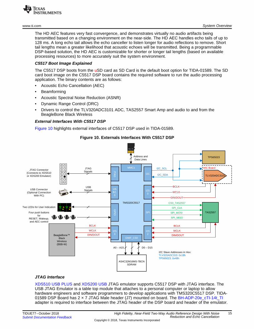
External Interfaces With C5517 DSPFigure 10 highlights external interfaces of C5517 DSP used in TIDA-01589.
Figure 10. Externals Interfaces With C5517 DSP
JTAG InterfaceXDS510 USB PLUS and XDS200 USB JTAG emulator supports C5517 DSP with JTAG interface. TheUSB JTAG Emulator is a table top module that attaches to a personal computer or laptop to allowhardware engineers and software programmers to develop applications with TMS320C5517 DSP. TIDA-01589 DSP Board has 2 × 7 JTAG Male header (J7) mounted on board. The BH-ADP-20e_cTI-14t_TIadapter is required to interface between the JTAG header of the DSP board and header of the emulator.

System Overview www.ti.com
16 TIDUE77–October 2018Submit Documentation Feedback
Copyright © 2018, Texas Instruments Incorporated
High Fidelity, Near-Field Two-Way Audio Reference Design With NoiseReduction and Echo Cancellation
The adapter plugs onto the 2 × 7 female connector of the emulator on one side and the 2 × 7 maleconnector of the DSP board on the other. This adapter resolves the voltage differences required forcorrect operation. Figure 27 shows the hardware connections for the JTAG connector on the DSP boardwith the emulator. JTAG connection with DSP board is not required to run the demonstration. It is onlyrequired for debugging and development purposes.
For more information on the JTAG interface implemented in this design, see the XDS510 USB JTAGEmulator Installation Guide.• I2S InterfaceThe C5517 DSP has a total of three I2S ports of which one is used to receive digital audio data from twomicrophones via the TLV320ADC3101 device, the second port is used to exchange audio data with theTAS2557 device to be played on the speaker and the third I2S port is used to pipe the audio in and out ofthe system to the BeagleBone black wireless.
2.3.4 Audio Out
2.3.4.1 Selection of SpeakerOne of the first steps in an audio design is to decide which speaker to use. There are many differentparameters to look at when making this decision: output power, SPL, size, cost, and more. TI’s SmartAmp products work with a wide variety of speakers on the market, and it is important to confirm thefollowing items to ensure highest audio quality:• Nominal speaker impedance: 4 to 32 Ω• Resonant frequency: 200 to 1400 Hz
If the speaker follows these guidelines, it will allow for the highest quality of TI audio at the maximumsound pressure level.
Speaker key specifications are as follows:1. Power rating2. Speaker impedance3. Sensitivity4. Rated frequency range5. Frequency response6. THD variation over frequency range7. Resonance frequency8. Speaker dispersion or directivity
For this design, SPS0916B-J-01 speaker is selected and the speaker wires connect to TerminalConnector (J15) mounted on TIDA-01589 DSP board. If any other speaker is selected for integrating inEnd system then speaker parameter should be obtained for selected speaker. TIDA-01589 SoftwarePackage already includes characterization files for SPS0916B-J-01 speaker.
Figure 13 highlights the step-by-step process from speaker characterization to end-system integration.
2.3.4.2 TAS2557 Smart Amp - 5.7-W Class-D Mono Audio Amplifier With Class-H Boost and SpeakerSense
The TAS2557 smart amplifier is a hybrid analog or digital device that includes several digital-signal-processing (DSP) blocks. A smart integrated multilevel Class-H boost converter maximizes systemefficiency at all times by tracking the required output voltage. The TAS2557 can drive up to 3.8 W from a4.2-V supply into an 8-Ω speaker with 1% THD, or up to up 5.7 W into a 4-Ω speaker with 1% THD. TheClass-D output switching frequency is synchronous with the digital input audio sample rate to avoid leftand right PWM frequency differences from beating in stereo applications. The PWM Edge rate control andSpread Spectrum features are available if further EMI reduction is desired. The TAS2557 internalprocessing algorithm automatically enables the boost when needed. A look-ahead algorithm monitors theinput voltage and the digital audio stream. When the speaker output approaches the input voltage the

www.ti.com System Overview
17TIDUE77–October 2018Submit Documentation Feedback
Copyright © 2018, Texas Instruments Incorporated
High Fidelity, Near-Field Two-Way Audio Reference Design With NoiseReduction and Echo Cancellation
boost is enabled in-time to supply the required speaker output voltage. When the boost is no longerrequired it is disabled and bypassed to maximize efficiency. The boost can be configured in one of twomodes. The first is low in-rush (Class-G) supporting only boost on-off and has the lowest in-rush current.The second is high-efficiency (Class-H) where the boost voltage level is adjusted to a value just abovewhat is needed. This mode is more efficient but has a higher in-rush current to quickly transition the levels.
Figure 11. Smart Amp Features Two Selectable Boost Functions
Figure 12 shows the TAS2557 functional block diagram:

BaseBand and
Application Processor
DIN1
Echo Canceller
Noise Canceller
DOUT1
WCLK1
BCLK1
DOUT2
WCLK2
BCLK2
MCLK
/RESET
ADR1
ADR0
SCL
SDA
IRQ_GPIO4
I2C Control
I/F
Control Registers
MUX
OC TripOver Temp
VBAT LOW
VBOOST
VBAT
PGND
+
-
2.2 µH
Boost Converter
SW SW
10-BitSAR ADC
OSCRC CLK
Temp Sensor
IV-Sense and Post-Filter Feedback
VBOOST LOW
BCLK1
BCLK2
MCLK
VBOOST
22 µF 10 nF
PVDD VREG
Class-D Amplifier
System Control
Missing Clock Detection and De-Pop and
Soft-Start
Audio Clocks
MCLK
VO
L_R
AM
P_D
own
Cla
ss-D
_PW
R_D
OW
N
SPK_P
SPK_M
4 ��WR�8 ��Speaker
VSENSE_P
VSENSE_M
Programmable PLL
DSPSound EnhancementVolume ControlSpeaker Excursion ProtectionSpeaker Temperature ProtectionDigital Interpolation FilteringDigital Decimation Filtering
Audio Serial Interface Port #1Programmable FormatMaster / SlaveI2S / TDM / DSP / PDMFs: 8 kHz to 96 kHz
Audio Serial Interface Port #2Programmable FormatMaster / SlaveI2S / TDM / DSP / PDMFs: 8 kHz to 96 kHz
�-¨ADC
VOL_RAMP_Down
Audio Serial Interface for Multi-Channel (ASIM)Programmable FormatMaster / SlaveI2S / TDM / DSP-LinkFs: 8 kHz to 96 kHz
�-¨ADC
AVDD DVDD IOVDD AGND DGND IOGND
System Overview www.ti.com
18 TIDUE77–October 2018Submit Documentation Feedback
Copyright © 2018, Texas Instruments Incorporated
High Fidelity, Near-Field Two-Way Audio Reference Design With NoiseReduction and Echo Cancellation
Figure 12. TAS2557 Block Diagram
Table 3 highlights recommended external components used for the TAS2557 design:
Table 3. Recommended External Components
COMPONENT DESCRIPTION SPECIFICATION MIN TYP MAX UNITSL16 Boost converter inductor Inductance, 20%
tolerance1 2.2 µH
Saturation current 3.1 AC108 Boost converter input
capacitorCapacitance, 20%tolerance
10 µF
L61 and L62 EMI filter inductors (optional).These are not recommendedbecause they degrade THD+Nperformance. The TAS2557device is a filter-less Class-Dand does not require thesebead inductors.
Impedance at 100 MHz 120 Ω
DC resistance 0.095DC current 2 ASize 0402
www.ti.com System Overview
19TIDUE77–October 2018Submit Documentation Feedback
Copyright © 2018, Texas Instruments Incorporated
High Fidelity, Near-Field Two-Way Audio Reference Design With NoiseReduction and Echo Cancellation
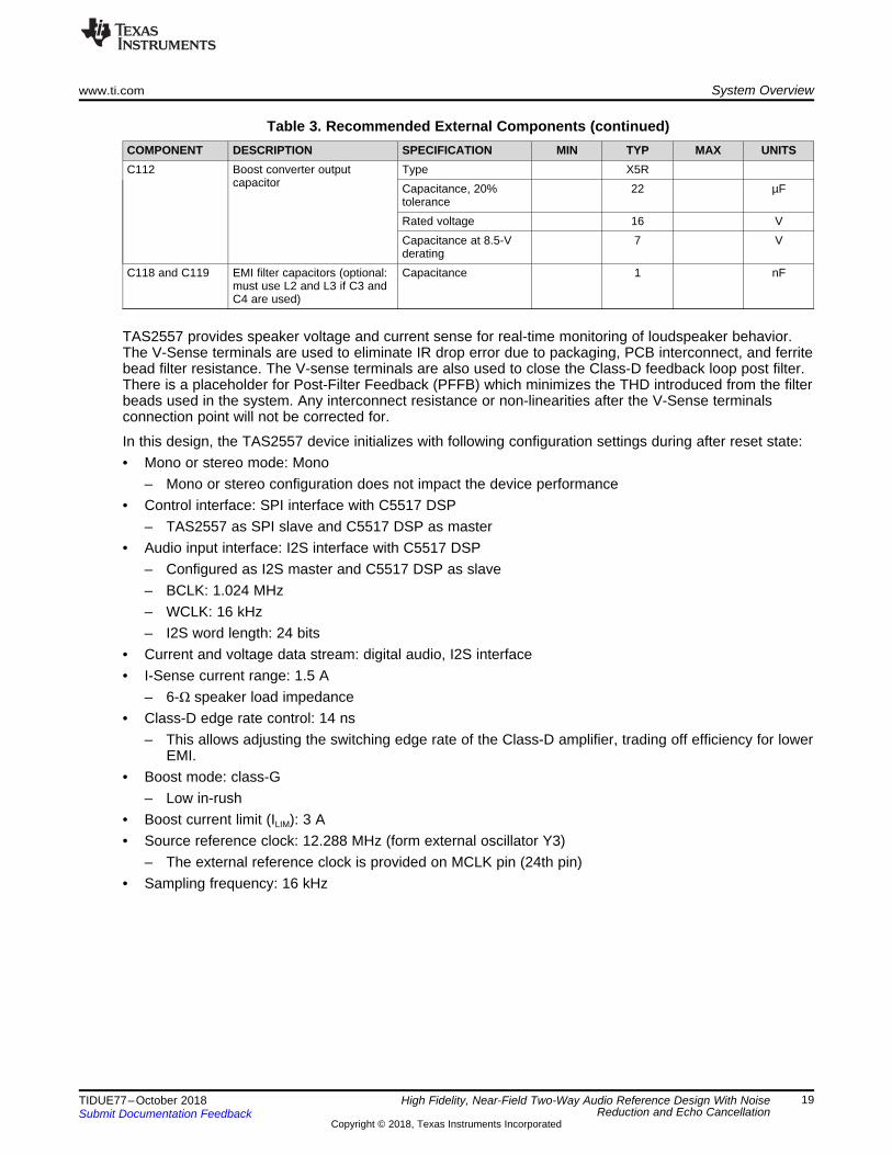
Table 3. Recommended External Components (continued)COMPONENT DESCRIPTION SPECIFICATION MIN TYP MAX UNITSC112 Boost converter output
capacitorType X5RCapacitance, 20%tolerance
22 µF
Rated voltage 16 VCapacitance at 8.5-Vderating
7 V
C118 and C119 EMI filter capacitors (optional:must use L2 and L3 if C3 andC4 are used)
Capacitance 1 nF
TAS2557 provides speaker voltage and current sense for real-time monitoring of loudspeaker behavior.The V-Sense terminals are used to eliminate IR drop error due to packaging, PCB interconnect, and ferritebead filter resistance. The V-sense terminals are also used to close the Class-D feedback loop post filter.There is a placeholder for Post-Filter Feedback (PFFB) which minimizes the THD introduced from the filterbeads used in the system. Any interconnect resistance or non-linearities after the V-Sense terminalsconnection point will not be corrected for.
In this design, the TAS2557 device initializes with following configuration settings during after reset state:• Mono or stereo mode: Mono
– Mono or stereo configuration does not impact the device performance• Control interface: SPI interface with C5517 DSP
– TAS2557 as SPI slave and C5517 DSP as master• Audio input interface: I2S interface with C5517 DSP
– Configured as I2S master and C5517 DSP as slave– BCLK: 1.024 MHz– WCLK: 16 kHz– I2S word length: 24 bits
• Current and voltage data stream: digital audio, I2S interface• I-Sense current range: 1.5 A
– 6-Ω speaker load impedance• Class-D edge rate control: 14 ns
– This allows adjusting the switching edge rate of the Class-D amplifier, trading off efficiency for lowerEMI.
• Boost mode: class-G– Low in-rush
• Boost current limit (ILIM): 3 A• Source reference clock: 12.288 MHz (form external oscillator Y3)
– The external reference clock is provided on MCLK pin (24th pin)• Sampling frequency: 16 kHz

Obtain Hardware and Software
Obtain Speaker Parameters
Speaker Tuning
End-System Integration
Complete
Start
Plan for Development
System Overview www.ti.com
20 TIDUE77–October 2018Submit Documentation Feedback
Copyright © 2018, Texas Instruments Incorporated
High Fidelity, Near-Field Two-Way Audio Reference Design With NoiseReduction and Echo Cancellation
2.3.4.2.1 TAS2557 Development OverviewFigure 13 summarizes step-by-step Smart Amp evaluation, planning, characterization, tuning and endsystem integration:
Figure 13. Smart Amp Development Flow
Obtaining TI Hardware and Software:Speaker characterization and tuning are performed using the PurePath™ Console 3 software. The TILearning Board 2 and the TAS2557EVM are needed to fully evaluate and develop with TAS2557 SmartAmp.• Order Learning Board 2 and TAS2557EVM from ti store.• TI approval is required to download Smart Amp-related hardware software. Click the button in the
TAS2557 device web site to begin the approval process. Once approved, the user receives an emailconfirming access to the mySecureSoftware web site. Download the PurePath™ Console 3 (PPC3)software from the PUREPATHCONSOLE software product page and TAS2557 App for PurePath™Console 3 on mySecureSoftware.
All the resources are available on TAS2557 Device and EVM folders.
NOTE: There is no need to download separate plugins – Smart Amp Applications are automaticallyavailable within the PurePath™ Console 3 once access is provided to the proper softwareproduct.
Contact [email protected] for any issues related to software access.
Plan for development:Developing Smart Amp-based systems for the first time is different than working with conventionalamplifiers. Information obtained during the speaker characterization process often leads to changes to thespeaker or enclosure to maximize output and quality.
www.ti.com System Overview
21TIDUE77–October 2018Submit Documentation Feedback
Copyright © 2018, Texas Instruments Incorporated
High Fidelity, Near-Field Two-Way Audio Reference Design With NoiseReduction and Echo Cancellation
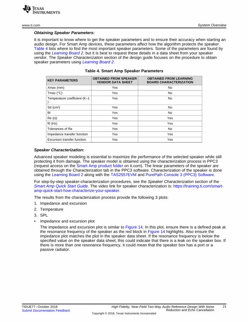
Obtaining Speaker Parameters:It is important to know where to get the speaker parameters and to ensure their accuracy when starting anaudio design. For Smart Amp devices, these parameters affect how the algorithm protects the speaker.Table 4 lists where to find the most important speaker parameters. Some of the parameters are found byusing the Learning Board 2, but it is best to request these details in a data sheet from your speakervendor. The Speaker Characterization section of the design guide focuses on the procedure to obtainspeaker parameters using Learning Board 2.
Table 4. Smart Amp Speaker Parameters
KEY PARAMETERS OBTAINED FROM SPEAKERVENDOR DATA SHEET
OBTAINED FROM LEARNINGBOARD CHARACTERIZATION
Xmax (mm) Yes NoTmax (°C) Yes NoTemperature coefficient (K–1)
Yes No
Sd (cm²) Yes NoBI Yes NoRe (Ω) Yes Yesf0 (Hz) Yes YesTolerances of Re Yes NoImpedance transfer function Yes YesExcursion transfer function Yes Yes
Speaker Characterization:Advanced speaker modeling is essential to maximize the performance of the selected speaker while stillprotecting it from damage. The speaker model is obtained using the characterization process in PPC3(request access on the Smart Amp product folder on ti.com). The linear parameters of the speaker areobtained through the Characterization tab in the PPC3 software. Characterization of the speaker is doneusing the Learning Board 2 along with the TAS2557EVM and PurePath Console 3 (PPC3) Software.
For step-by-step speaker-characterization procedures, see the Speaker Characterization section of theSmart Amp Quick Start Guide. The video link for speaker characterization is: https://training.ti.com/smart-amp-quick-start-how-characterize-your-speaker.
The results from the characterization process provide the following 3 plots:1. Impedance and excursion2. Temperature3. SPL• Impedance and excursion plot
The impedance and excursion plot is similar to Figure 14. In this plot, ensure there is a defined peak atthe resonance frequency of the speaker as the red block in Figure 14 highlights. Also ensure theimpedance plot matches the plot in the speaker data sheet. If the resonance frequency is below thespecified value on the speaker data sheet, this could indicate that there is a leak on the speaker box. Ifthere is more than one resonance frequency, it could mean that the speaker box has a port or apassive radiator.

System Overview www.ti.com
22 TIDUE77–October 2018Submit Documentation Feedback
Copyright © 2018, Texas Instruments Incorporated
High Fidelity, Near-Field Two-Way Audio Reference Design With NoiseReduction and Echo Cancellation
Figure 14. Impedance and Excursion Plot
• Temperature PlotThe temperature plot from the characterization will look similar to Figure 15. Ensure there the speakerheats up to the maximum temperature of the speaker which is 75°C in Figure 15
Figure 15. Temperature Plot
• SPL PlotThe SPL plot will look similar to the plot in Figure 16. Lower frequencies (< 100 Hz) in the SPL plotshow room noise, but they will not be used by the Smart Amp. To ensure the speaker is in a sealedenclosure (closed box), check to see if there is a peak at the resonance frequency of the speakers.
Figure 16. SPL Measurement Plot
Speaker Tuning:Micro-speakers are especially limited in maximum SPL and bass response due to the small diaphragmsize; however, the smart amp allows the user to tune the speaker to achieve the maximum audio qualityfrom a limited speaker. Application specific speaker tuning is important to optimize the sound quality andSPL of a speaker. An example of this may be to have the highest quality sound for voice in a videodoorbell, thermostat, and so forth. The TAS2557 Smart Amp allows custom speaker tuning all within thePPC3 Software GUI. PPC3 enables speaker tuning using 10 biquads and features like PsychoacousticBass Enhancer, and Dynamic Range Compression to mention a few.

www.ti.com System Overview
23TIDUE77–October 2018Submit Documentation Feedback
Copyright © 2018, Texas Instruments Incorporated
High Fidelity, Near-Field Two-Way Audio Reference Design With NoiseReduction and Echo Cancellation
It is assumed that the speaker parameters, such as the Re, Bl, Xmax, Tmax, Sd, Thiele-Small model, andtemperature model are measured and loaded correctly into the .ppc3 file before proceeding with thetuning. Import parameters from one .ppc3 file to another or enter them manually, if acquired by othermeans. For step-by-step speaker-tuning procedures, see the Speaker Tuning section of the Smart AmpTuning Guide.
End System Integration:The End System Integration step creates the final binary file for the end system driver to load. The finalstep of the Smart Amp Process is the End System Integration Step. Once this step is complete, users willbe on your way in using TAS2557 to drive the audio requirements of the system. For step-by-stepprocedures on end-system integration, see the System Integration Guidance section of the Smart AmpTuning Guide.
NOTE: For more information on the end-system integration process, refer to the TAS2555 End-System Integration Guide.
Speaker parameters may vary from the vendor data sheet. This can lead to inaccurate speaker protectionin situations where one speaker model is used to fit all speakers. For this reason, the TAS2557 SmartAmp algorithm can be calibrated to the specific speaker parameters to ensure protection of the speaker ona speaker by speaker basis. The Factory Test and Calibration (FTC) is performed to calibrate the SmartAmp algorithm and protect the speaker from speaker parameter variations. The FTC obtains the speakerRe0, f0, Q, and voice coil temperature. TI recommends the FTC is performed on all units to ensureprotection of the speaker. For step-by-step procedures on Factory Test and Calibration (FTC), see theFactory Test and Calibration (FTC) Implementation section of the Smart Amp Tuning Guide.
NOTE: For more information on the tuning factory test and calibration, see the TAS2555, TAS2557,and TAS2559 Factory Test and Calibration Guide.
2.3.5 Connectivity With BeagleBone™ Black WirelessTIDA-01589 DSP board is designed as a “cape” for BeagleBone Black Wireless (BBB-W), which is usedwith this design to complete the two-way audio demonstration. AM335x Linux Processor SoftwareDevelopment Kit 5.0 (PSDK-Linux) supports the BeagleBone Black-Wireless and is used as the baselinekit for development of this demo. To run this demo, a dummy codec driver in Linux called “generic 2-way”is created to provide support for audio input and audio output. The device is referred to as a dummy codecbecause there is no specific hardware codec device being used. The main purpose of this driver is tofacilitate moving audio from the audio serial port (McASP) driver level to the ALSA layer. In addition toadding a codec driver, Linux device tree changes are also required in order to configure the audio I/Oconnections between the AM335x and the codec. The McASP on the AM335x processor must beconfigured as a slave since the TAS2557 is responsible for generating the clocks in this design.
A multimedia framework called Gstreamer is used to capture and playback real time audio on the BBB-W.Upon boot, the USB dongle is detected by the BBB-W and two Linux audio services are startedconcurrently. Each service calls a python script that is responsible for calling a Gstreamer command. OneGstreamer command transfers audio from the DSP board to be played back over the headphone. Thesecond command moves captured audio from the headset microphone to the DSP board. The flow fromthese commands are depicted in Figure 17, as the green line and black line, respectively.

%HDJOH%RQH�
Black Wireless(BBB-W)
Acoustic Echo Canceller
Noise Reduction
Pre-AEC Digital Gain
Post AEC Digital Gain
Digital GainI2S2RX Out
TMS320C5517
MSS
ExternalMemory
I2S0
BF 18°
BF 36°
BF 54°
BF 72°
Near-side Talker Far-side Talker
- Adaptive Digital VQE Software
DSP Board
TAS2557
I2S3
MIC Board
TLV320ADC3101
Speaker for Audio Output
xxx
x
x xx
x
System Overview www.ti.com
24 TIDUE77–October 2018Submit Documentation Feedback
Copyright © 2018, Texas Instruments Incorporated
High Fidelity, Near-Field Two-Way Audio Reference Design With NoiseReduction and Echo Cancellation
Figure 17. Gstreamer Script Flow
The TAS2557 on the DSP board is required to be initialized before the “USR3” LED illuminates on theBeagleBone black wireless. This allows the proper clocks to be provided to the BeagleBone black wirelessfrom the system master, and subsequently start the audio application by calling the Gstreamer commands.

www.ti.com Hardware, Software, Testing Requirements, and Test Results
25TIDUE77–October 2018Submit Documentation Feedback
Copyright © 2018, Texas Instruments Incorporated
High Fidelity, Near-Field Two-Way Audio Reference Design With NoiseReduction and Echo Cancellation
3 Hardware, Software, Testing Requirements, and Test Results
3.1 Required Hardware and Software
3.1.1 Getting Started Hardware
3.1.1.1 PrerequisitesTo properly setup the hardware connections with TIDA-01589, the following tools are required:• DC adapter with 5-V, 6.5-A output rating• BeagleBone Black Wireless (BBB-W)• XDS200 USB or XDS510 USB PLUS JTAG Emulator (Optional: Not required to run demo)• 20-pin compact TI (cTI) header to the standard 14-pin target JTAG header (Optional: Not required to
run demo)– Manufacturer part number: BH-ADP-20e_cTI-14t_TI
• Two Micro SD Cards for Booting TIDA-01589 DSP Board and Beaglebone black wireless• USB Audio Adapter
– Manufacturer part number: SD-CM-UAUD• External Headset with microphone with separate microphone and headphone cable or Normal
Headset/earphone with Microphone along with MIC and Headphone splitter cable– Manufacturer part number for Headset with separate microphone and headphone cable: 87070
• Two 3.5-mm male auxiliary to 3.5-mm female stereo audio extension cables– Manufacture part number: 25 Feet cable or 15 Feet cable
• TIDA-01589 Smartkit– TIDA-01589 MIC Board– TIDA-01589 DSP Board with Micro-speaker attached– Ribbon Cable to connect MIC and DSP Board
3.1.2 Getting Started Firmware
3.1.2.1 PrerequisitesTo run the audio demonstration on the DSP board and BeagleBone Black Wireless, there are twosoftware images that are required:1. bootimg.bin – This is the binary that needs to be flash on the SD card for the TMS320C5517 DSP on
DSP board.2. BBB-W.zip – This directory needs to decompressed and the files are written on SD card for the
BeagleBone Black Wireless.
NOTE: Software images for BeagleBone black wireless and TIDA-01589 DSP board are provided byAdaptive Digital. Contact Adaptive Digital for getting Boot images.

SD Card With Preloaded Boot Image Inserted Into TIDA-01589 DSP Board
Hardware, Software, Testing Requirements, and Test Results www.ti.com
26 TIDUE77–October 2018Submit Documentation Feedback
Copyright © 2018, Texas Instruments Incorporated
High Fidelity, Near-Field Two-Way Audio Reference Design With NoiseReduction and Echo Cancellation
3.2 Testing and Results
3.2.1 TIDA-01589 DSP board Software Setup• Download Boot image for DSP board in PC and format the SD card in either FAT32 or FAT16 format• Copy the downloaded ".bin" (ex: bootimg.bin) file to the formatted SD Card under root partition
(filename MUST BE "bootimg.bin")
3.2.2 BeagleBone™ Black Wireless Software SetupSD Card setup:• Download Boot image for BeagleBone black wireless in PC and use this image file to create a SD
Card containing the embedded Linux system provided with the Linux SDKTo create the SD card, see Windows SD Card Creation Guide. In short, SD card creation processinvolves writing download image to uSD card.
• After SD card creation, eject the SD card from PC and Insert SD card with preloaded boot image intoBeagleBone™ Black Wireless as shown in Figure 18
Figure 18. SD Card With Pre-Loaded Boot Image Inserted Into BeagleBone™ Black Wireless
BeagleBone Black Wireless Terminal Setup:• Connect a FTDI cable to BeagleBone Black Wireless as shown in Figure 19

www.ti.com Hardware, Software, Testing Requirements, and Test Results
27TIDUE77–October 2018Submit Documentation Feedback
Copyright © 2018, Texas Instruments Incorporated
High Fidelity, Near-Field Two-Way Audio Reference Design With NoiseReduction and Echo Cancellation
Figure 19. FTDI Cable Connected to BeagleBone™ Black Wireless
NOTE: The black wire will be next to the TP6/X1 marker and connects the USB to the PC.
• Users can connect to the BeagleBone Black Wireless via a serial console of their choice and boot thedevice. The settings are shown in Figure 20
Figure 20. Serial Port Settings
BeagleBone Black Wireless (BBB-W) SD card boot:• By default, BeagleBone Black Wireless boots from the External MMC. To boot from the SD card, press
and hold the S2 switch on BeagleBone Black Wireless and apply 5-V power to the BBB-W using DCAdapter.
Hardware, Software, Testing Requirements, and Test Results www.ti.com
28 TIDUE77–October 2018Submit Documentation Feedback
Copyright © 2018, Texas Instruments Incorporated
High Fidelity, Near-Field Two-Way Audio Reference Design With NoiseReduction and Echo Cancellation
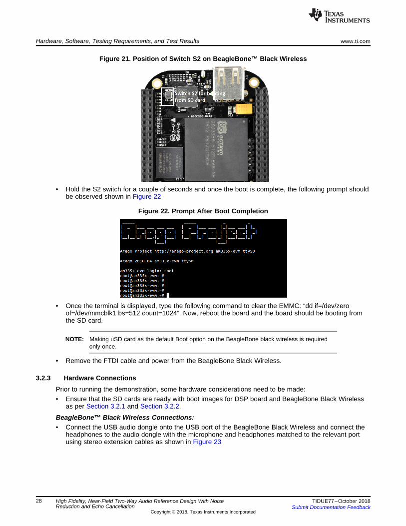
Figure 21. Position of Switch S2 on BeagleBone™ Black Wireless
• Hold the S2 switch for a couple of seconds and once the boot is complete, the following prompt shouldbe observed shown in Figure 22
Figure 22. Prompt After Boot Completion
• Once the terminal is displayed, type the following command to clear the EMMC: “dd if=/dev/zeroof=/dev/mmcblk1 bs=512 count=1024”. Now, reboot the board and the board should be booting fromthe SD card.
NOTE: Making uSD card as the default Boot option on the BeagleBone black wireless is requiredonly once.
• Remove the FTDI cable and power from the BeagleBone Black Wireless.
3.2.3 Hardware ConnectionsPrior to running the demonstration, some hardware considerations need to be made:• Ensure that the SD cards are ready with boot images for DSP board and BeagleBone Black Wireless
as per Section 3.2.1 and Section 3.2.2.
BeagleBone™ Black Wireless Connections:• Connect the USB audio dongle onto the USB port of the BeagleBone Black Wireless and connect the
headphones to the audio dongle with the microphone and headphones matched to the relevant portusing stereo extension cables as shown in Figure 23

SD Card With Preloaded Boot Image Inserted Into TIDA-01589 DSP Board
%HDJOH%RQH��%ODFN�:LUHOHVV
USB Audio Adapter
MIC input and Headphone output
connected to %HDJOH%RQH��YLD�
USB Audio Adapter
www.ti.com Hardware, Software, Testing Requirements, and Test Results
29TIDUE77–October 2018Submit Documentation Feedback
Copyright © 2018, Texas Instruments Incorporated
High Fidelity, Near-Field Two-Way Audio Reference Design With NoiseReduction and Echo Cancellation
Figure 23. Headset Connected to BeagleBone™ Black Wireless via USB Audio Adapter
DSP Board connections:• Insert other SD card with preloaded boot image into DSP board as Figure 24 shows.
Figure 24. SD Card With Pre-Loaded Boot Image Inserted Into DSP Board
• Couple the BeagleBone Black Wireless (BBB-W) and the DSP board by placing the DSP board on topof the BBB-W. Ensure the orientation of the boards prior to combining are correct as shown inFigure 25. The DC Jack of BBB-W and DSP board should be aligned vertically after proper mating asshown in Figure 26

DSP Board
JTAG connection is only required for debugging/development purposes
Ribbon cable connected to MIC Board Speaker wires connected
to Terminal connector J15
Ribbon cable connected to DSP Board
JTAG Emulator connected to DSP Board
MIC Board
Hardware, Software, Testing Requirements, and Test Results www.ti.com
30 TIDUE77–October 2018Submit Documentation Feedback
Copyright © 2018, Texas Instruments Incorporated
High Fidelity, Near-Field Two-Way Audio Reference Design With NoiseReduction and Echo Cancellation
Figure 25. DSP Board Sitting on top of BeagleBone™ BlackWireless
Figure 26. DSP Board Sitting on top of BeagleBone™ BlackWireless With DC Jacks Aligned
• Attach the speaker on the DSP audio board by screwing in the wires from the speaker onto theterminal connector J15 as shown in Figure 27. The polarity is not important for the speaker wires.
• Connect one end of the ribbon cable on the J1 connector of the DSP board as Figure 27 shows.
Figure 27. MIC Board and Speaker Wires Connected to DSP Board
NOTE: The JTAG connection with the DSP board is not required to run the demonstration. It is onlyrequired for debugging and development purposes.

External MIC Attached to Headset
USB Audio Adapter$WWDFKHG�WR�%HDJOH%RQH��
Black Wireless
Ribbon CableConnecting to MIC
and DSP Board
5-V DC AdapterConnected to DSP Board
MIC Input and Headphone Output Connected to Adapter
Using Stereo Extension Cables
www.ti.com Hardware, Software, Testing Requirements, and Test Results
31TIDUE77–October 2018Submit Documentation Feedback
Copyright © 2018, Texas Instruments Incorporated
High Fidelity, Near-Field Two-Way Audio Reference Design With NoiseReduction and Echo Cancellation
MIC board Connections:• Connect other end of the ribbon cable on the microphone board as shown in Figure 27. The cable can
only be inserted in a fixed direction and not be reversed.• At last, connect a 5-V DC Adapter to Power Jack J10 on the DSP board. This will ensure both the
BeagleBone Black Wireless and DSP board are powered.
Figure 28. TIDA-01589 Demonstration Setup

Power Indication LEDs on DSP
board
Power on Beaglebone
Black Wireless
Hardware, Software, Testing Requirements, and Test Results www.ti.com
32 TIDUE77–October 2018Submit Documentation Feedback
Copyright © 2018, Texas Instruments Incorporated
High Fidelity, Near-Field Two-Way Audio Reference Design With NoiseReduction and Echo Cancellation
3.2.4 Test Board PreparationAfter connecting a 5-V DC adapter to the DSP board, the following LEDs are present onboard forindicating user on proper power-up and booting operation:
LED indications of power:• Two green power LEDs Vin_5V and VDD_BBB will indicate power being supplied to the DSP board
and BBB-W respectively as shown in Figure 29• The blue power LED on the BeagleBone Black Wireless indicates power on the BBB-W as Figure 30
shows.
Figure 29. Power Indication LEDs on DSP Board Figure 30. Power Indication LED BeagleBone™ Black Wireless
• The Blue power LED on the MIC board indicates the power on the board as Figure 31 shows.
Figure 31. Power Indication LED on MIC Board

Boot Indication LED on Beaglebone
www.ti.com Hardware, Software, Testing Requirements, and Test Results
33TIDUE77–October 2018Submit Documentation Feedback
Copyright © 2018, Texas Instruments Incorporated
High Fidelity, Near-Field Two-Way Audio Reference Design With NoiseReduction and Echo Cancellation
LED indications of Booting and Initialization:• The Linux image will be boot of the SD card on the BeagleBone Black Wireless and USRx LEDs on
the BeagleBone Black Wireless will indicate successful boot of the Linux Kernel as shown in Figure 32
Figure 32. Boot Indication LEDs on BeagleBone™ Black Wireless
NOTE: After a successful boot, the USR3 LED on the BeagleBone black wireless glowscontinuously. DSP board boots much faster than Beaglebone Black Wireless.
• Two red LEDs D1 and D2 on the MIC board glow continuously indicating the presence of MIC BIAS asFigure 33 shows.
Figure 33. MIC BIAS and ADC3101 Initialization Indication LEDs on MIC Board
• Blue LEDs D3 and D4 on MIC board will illuminate indicating a successful initialization of theTLV320ADC3101 as shown in Figure 33
AEC and NR Enable/Disable Indication LEDs:• Green LED LED0 on DSP board indicates enable or disable status of Acoustic Echo Cancellation
(AEC) running on C5517 DSP. LED0 glows continuously when AEC is enabled.• Green LED LED1 on DSP board indicates enable or disable status of Noise Reduction (NR) running on
C5517 DSP. LED1 glows continuously when NR is enabled.

xxxx
%HDJOH%RQH��%ODFN
Wireless (BBB-W)
TIDA-01589 DSP Board
TIDA-01589 MIC Board
MIC1 MIC2
5-V DC Jack
Universal 5-V DC Adapter
Ribbon Cable Connecting MIC and
DSP Board
Near-side Talker Far-side Talker
USB Audio
Adapter
MIC Input From Headset to BBB-W via USB Audio
Adapter
Headphone Output from BBB-W to Headset via
USB Audio Adapter
15 ± 25 Feet long
cable
Optional JTAG Connectivity With TMS320C5517: Not Required to run Demo
SD Card for Booting DSP board
SD Card for %RRWLQJ�%HDJOH%RQH�
20 to 14 pin Adapter
10 × 2 JTAG Male Header
Mating Connectors
Speaker Connector
Dynamic Speaker
*Dynamic Speaker is attached to DSP board
AEC and NR Control Push
Buttons
XDS200/XDS510
JTAG Emulator
CCS Running on PC
xxxx
7 × 2 JTAG Male Header
LED0 and LED1on DSP board
Hardware, Software, Testing Requirements, and Test Results www.ti.com
34 TIDUE77–October 2018Submit Documentation Feedback
Copyright © 2018, Texas Instruments Incorporated
High Fidelity, Near-Field Two-Way Audio Reference Design With NoiseReduction and Echo Cancellation
Figure 34. LED0 and LED1 for Enable or Disable Status of AEC and NR
3.2.5 Test Setup
Figure 35. TIDA-01589 Test Setup
3.2.6 Test ProcedureOnce the DSP board and beaglebone black wireless are able to boot successfully, verify proper operationby following procedure:1. Speak in normal tones from a normal distance into the MIC board. The audio captured by the MIC
board should be transmitted and audible through the headset attached to the beaglebone blackwireless via audio adapter.
2. Speak in normal tones into the microphone that is part of the headset. The audio should be heardthrough the external speaker attached to the DSP board.
If each of these tests are successful, the boards and demonstration is operating properly. Proceed toSection 3.2.6.1 and Section 3.2.6.2 for further testing.

AEC and NR enable/disable push buttons on DSP board
www.ti.com Hardware, Software, Testing Requirements, and Test Results
35TIDUE77–October 2018Submit Documentation Feedback
Copyright © 2018, Texas Instruments Incorporated
High Fidelity, Near-Field Two-Way Audio Reference Design With NoiseReduction and Echo Cancellation
If the tests are not successful, remove power from DSP board and review the steps in Section 3.2.1,Section 3.2.2 and Section 3.2.3 to make sure each connection is correct and robust. Proceed to reviewingthe software setup steps and try again.
3.2.6.1 Audio Echo Cancellation testing1. With both boards booted successfully, test the functionality of audio echo canceller running on C5517
DSP.2. By default, the AEC is enabled. Speak into the far-end microphone(attached to Headset) and the near-
end speaker(attached to DSP board) outputs the audio without any echo being heard on the far-endspeaker. Test the same in the reverse direction by speaking into the mic board on the near-end, andthe spoken audio is heard out of the far-end headphones without hearing any echo back on the near-end.
3. LED0 on DSP board glows continuously when AEC is enabled.4. Press switch S1 on the DSP board to disable the AEC functionality. Speak into either microphone and
echoed speech should now be observed. Press switch S1 to enable AEC again.
Figure 36. Enable and Disable AEC Push Buttons on DSP Board
3.2.6.2 Noise Reduction Testing1. By default, NR is enabled, With a source of white noise playing close to the MIC board (near-end),
speak into the MIC board and observe the output of the audio on micro-speaker attached to speaker.The audio will have noise eliminated from the speech as a result of the Adaptive Spectral NoiseReduction (ASNR) algorithm executing on the C5517 DSP. To better observe the noise suppressionlevels, it is recommended to record the audio on a PC and use software such as Audacity to evaluatethe audio spectrum.
2. LED1 on DSP board glows continuously when NR is enabled.3. Press switch S2 on the DSP board to disable the NR functionality and notice the difference. Press
switch S2 to enable NR again.

Hardware, Software, Testing Requirements, and Test Results www.ti.com
36 TIDUE77–October 2018Submit Documentation Feedback
Copyright © 2018, Texas Instruments Incorporated
High Fidelity, Near-Field Two-Way Audio Reference Design With NoiseReduction and Echo Cancellation
3.2.7 Test ResultsTable 5 provides MIPS and memory usage data of different algorithms running on C5517 DSP
Table 5. MIPS and Memory Usage Data
DSPALGORITHM
MIPSAVERAGE,
PEAK
MEMORY (BYTES) INSTANCE DATA (BYTES)PROGRAM DATA TOTAL INSTANCE
SIZENUMBER
INSTANCESTOTAL
FixedBeamformer
9.2 avg 6844 344 7188 1360 2 27209.3 peak
Noisereduction
13.2 avg 7429 1926 9355 4886 2 977213.5 peak
HD AEC 113.1 avg 54617 11608 66225 67120 1 67120131.1 peak
Full DSPApplication
136.6 avg 308142157.3 peak
NOTE: All program and data fits on the internal memory of the C5517 DSP. The external SDRAM isused to only store uninitialized data capture buffers.

www.ti.com Design Files
37TIDUE77–October 2018Submit Documentation Feedback
Copyright © 2018, Texas Instruments Incorporated
High Fidelity, Near-Field Two-Way Audio Reference Design With NoiseReduction and Echo Cancellation
4 Design Files
4.1 SchematicsTo download the schematics, see the design files at TIDA-01589.
4.2 Bill of MaterialsTo download the bill of materials (BOM), see the design files at TIDA-01589.
4.3 PCB Layout Recommendations
4.3.1 Layout PrintsTo download the layer plots, see the design files at TIDA-01589.
4.4 Altium ProjectTo download the Altium Designer® project files, see the design files at TIDA-01589.
4.5 Gerber FilesTo download the Gerber files, see the design files at TIDA-01589.
4.6 Assembly DrawingsTo download the assembly drawings, see the design files at TIDA-01589.
5 Software FilesTo download the software files, see the design files at TIDA-01589.
6 Related Documentation
1. MICROPHONE SPECIFICATIONS EXPLAINED Application Note2. XDS510 USB JTAG Emulator Installation Guide3. Texas Instruments, TMS320C5517 Digital Signal Processor Technical Reference Manual4. Texas Instruments, C55x v3.x CPU Reference Guide5. Texas Instruments, Power Estimation and Power Consumption Summary for TMS320C5517 Device
Application Report6. Texas Instruments, Sitara™ Linux ALSA DSP Microphone Array Voice Recognition Application Report7. Texas Instruments, Usage Guidelines for C55x On-Chip Low Dropout Regulators (LDOs) Application
Report8. Texas Instruments, Smart Amp Quick Start Guide Application Report9. Texas Instruments, Getting Started with Smart Amp Development10. Texas Instruments, Smart Amp Tuning Guide Application Report11. Texas Instruments, TAS2557 and TAS2559 End-System Integration Guide Application Report12. Texas Instruments, TAS2555, TAS2557, and TAS2559 Factory Test and Calibration Guide Application
Report13. Make Your Audio System Sound Better with Smart Amp Technology14. Texas Instruments, SmartPA Speaker Protection Algorithm Application Report

About the Author www.ti.com
38 TIDUE77–October 2018Submit Documentation Feedback
Copyright © 2018, Texas Instruments Incorporated
High Fidelity, Near-Field Two-Way Audio Reference Design With NoiseReduction and Echo Cancellation
6.1 TrademarksE2E, PurePath, C5000 are trademarks of Texas Instruments.HD AEC is a trademark of Adaptive Digital Technologies, Inc..Altium Designer is a registered trademark of Altium LLC or its affiliated companies.Wi-Fi is a registered trademark of Wi-Fi Alliance.BeagleBone is a trademark of beagleboard.org.All other trademarks are the property of their respective owners.
7 About the AuthorSURYA MISHRA is a systems engineer at Texas Instruments where he is responsible for developingreference design solutions for the Building Automation, Industrial Segment. Surya earned his bachelor ofelectronics and communication engineering from the Motilal Nehru National Institute of Technology(MNNIT), Allahabad.

IMPORTANT NOTICE AND DISCLAIMER
TI PROVIDES TECHNICAL AND RELIABILITY DATA (INCLUDING DATASHEETS), DESIGN RESOURCES (INCLUDING REFERENCEDESIGNS), APPLICATION OR OTHER DESIGN ADVICE, WEB TOOLS, SAFETY INFORMATION, AND OTHER RESOURCES “AS IS”AND WITH ALL FAULTS, AND DISCLAIMS ALL WARRANTIES, EXPRESS AND IMPLIED, INCLUDING WITHOUT LIMITATION ANYIMPLIED WARRANTIES OF MERCHANTABILITY, FITNESS FOR A PARTICULAR PURPOSE OR NON-INFRINGEMENT OF THIRDPARTY INTELLECTUAL PROPERTY RIGHTS.These resources are intended for skilled developers designing with TI products. You are solely responsible for (1) selecting the appropriateTI products for your application, (2) designing, validating and testing your application, and (3) ensuring your application meets applicablestandards, and any other safety, security, or other requirements. These resources are subject to change without notice. TI grants youpermission to use these resources only for development of an application that uses the TI products described in the resource. Otherreproduction and display of these resources is prohibited. No license is granted to any other TI intellectual property right or to any thirdparty intellectual property right. TI disclaims responsibility for, and you will fully indemnify TI and its representatives against, any claims,damages, costs, losses, and liabilities arising out of your use of these resources.TI’s products are provided subject to TI’s Terms of Sale (www.ti.com/legal/termsofsale.html) or other applicable terms available either onti.com or provided in conjunction with such TI products. TI’s provision of these resources does not expand or otherwise alter TI’s applicablewarranties or warranty disclaimers for TI products.
Mailing Address: Texas Instruments, Post Office Box 655303, Dallas, Texas 75265Copyright © 2018, Texas Instruments Incorporated