Embed Size (px)
Citation preview

High-end solution
STEP-BY-STEP USER GUIDE
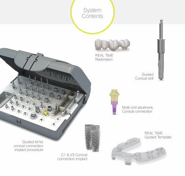
System Contents
Guided kit for conical connection implant procedure
Guided Conical drill
REAL TIME Restoration
Multi-Unit abutment, Conical connection
C1 & V3 Conical connection implant
REAL TIME Guided Template
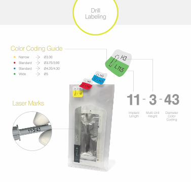
Color Coding GuideNarrow Ø3.30
Standard Ø3.75/3.90
Standard Ø4.20/4.30
Wide Ø5
ImplantLength
Multi-Unit Height
DiameterColor
Coding
Laser Marks - -
Drill Labeling
MG
1-D
0602
4
MG
1-D
1132
4
MG
1-D
1133
3
MG
1-D
1133
9
Ø4.20 / L11.5
MG
1-D
1134
3
MG
1-D
0602
4
MG
1-B
M04
8
MG
1-D
1132
4
MG
1-D
1133
3
MG
1-D
1133
9
Ø4.20 / L11.5
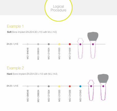
Soft Bone Implant Ø4.20/4.30 L11.5 with M.U. H=3;
Hard Bone Implant Ø4.20/4.30 L11.5 with M.U. H=3;
Example 1
Example 2
MG
1-B
M04
8
Logical Procedure
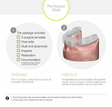
Initial try-inIt is essential to try-in the template in the patient’s mouth, prior to surgery. Correct seating and stability of the template must be confirmed.
2The package includes:
A surgical template Final drills Multi-Unit abutments Implants Restoration Documentation
(Including information specific to each planned implant.)
1
VerificationPrior to surgery, verify that you have all necessary components.
Pre-Surgical Steps
• Ensure that guide, plan and documentation are all made according to the specifications. • In rare cases, minor adjustments may be required.
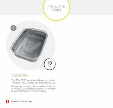
The REAL TIME template is shipped non-sterile. Therefore, it must undergo disinfection prior to use.
Recommended protocol: completely immerse in a 0.2% Chlorhexidine solution for 10 minutes at room temperature prior to surgery.
Disinfection
Caution! Do not autoclave.
3
Pre-Surgical Steps
10min.
Precautions
General • All REAL TIME drills and instruments are for use ONLY with the REAL TIME surgical template.
• Inspect all instruments prior to each surgery and replace if broken or dull.
• Ensure cooling of cutting instruments with sterile saline solution.
• Replace cutting instruments after 30 uses.
• Implants should be loaded only if significant primary stability is achieved.
• Guided conical drills should be used for a single surgery, do not autoclave single use drills!
Handling • Hold the template firmly while drilling.
• Avoid any lateral pressure on the instruments, as it may result in a shift in template position, detachment of the template or damage to instruments.
• Use an ‘in-out’ motion while drilling, slowly inserting the drill until the built-in stopper touches the top part of the template.
• Do not over-tighten implant insertion tools. It may result in a shift in template position or damage to the template.
• Make sure that the cross pin is fully inserted into the template and insertion tool.

1
2
Drills and tools MUST engage the template before turning is started.
Precautions
1
22
1
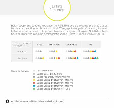
Built-in stopper and centering mechanism: All REAL TIME drills are designed to engage a guide template for correct function. Drills and tools MUST engage the template before turning is started. Follow drill sequence based on the planned diameter and length of each implant, Multi-Unit abutment height and bone type. Sequence is demonstrated using a 11.5mm C1 implant with Multi-Unit H3:
Drilling Sequence
All drills are laser marked to ensure the correct drill length is used.
Implant Ø Bone Type Ø3.30 Ø3.75/3.90 Ø4.20/4.30 Ø5
Soft Bone
Hard Bone
Key to codes use: Bone Mill Ø5.0mm
Guided Starter drill Ø2.40mm
Guided Pilot drill Ø2.40mm x 11+3mm
Guided Conical drill Ø3.30mm x 11+3mm
Guided Conical drill Ø3.90mm x 11+3mm
Guided Conical drill Ø4.30mm x 11+3mm
Guided Conical drill Ø5mm x 11+3mm
• Do not use the last drill for Soft bone (type 3&4). • The drilling sequence is demonstrated using an 11.5mm C1 implant with Multi-Unit H3. • Procedure recommended by MIS cannot replace the judgment and professional experience of the surgeon. • Multi-Unit abutment should be torqued to a min. 20Ncm during surgery (30Ncm after implant have osseointegrated).
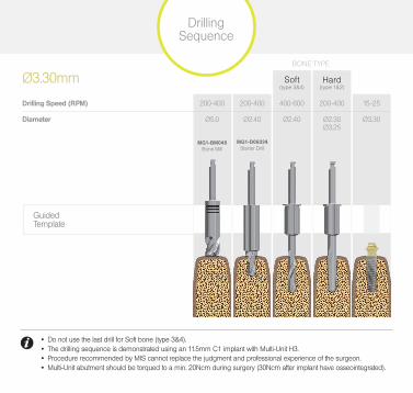
Ø3.30mm
Drilling Speed (RPM)
Diameter
(type 1&2)(type 3&4)Soft Hard
200-400
Ø5.0
MG1-BM048 Bone Mill
200-400
Ø2.40
MG1-D06024 Starter Drill
400-600
Ø2.40
200-400
Ø2.30Ø3.25
15-25
Ø3.30
Drilling Sequence
BONE TYPE
Guided Template
• Do not use the last drill for Soft bone (type 3&4). • The drilling sequence is demonstrated using an 11.5mm C1 implant with Multi-Unit H3. • Procedure recommended by MIS cannot replace the judgment and professional experience of the surgeon. • Multi-Unit abutment should be torqued to a min. 20Ncm during surgery (30Ncm after implant have osseointegrated).
• Do not use the last drill for Soft bone (type 3&4). • The drilling sequence is demonstrated using an 11.5mm C1 implant with Multi-Unit H3. • Procedure recommended by MIS cannot replace the judgment and professional experience of the surgeon. • Multi-Unit abutment should be torqued to a min. 20Ncm during surgery (30Ncm after implant have osseointegrated).
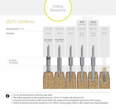
Ø3.75 / Ø3.90mm
Diameter
Drilling Speed (RPM)
(type 3&4)Soft
(type 1&2)Hard
200-400
Ø5.0
MG1-BM048 Bone Mill
200-400
Ø2.40
MG1-D06024 Starter Drill
400-600
Ø2.40
200-400
Ø2.30Ø3.25
200-400
Ø2.90Ø3.85
15-25
Ø3.75
Guided Template
Drilling Sequence
BONE TYPE
• Do not use the last drill for Soft bone (type 3&4). • The drilling sequence is demonstrated using an 11.5mm C1 implant with Multi-Unit H3. • Procedure recommended by MIS cannot replace the judgment and professional experience of the surgeon. • Multi-Unit abutment should be torqued to a min. 20Ncm during surgery (30Ncm after implant have osseointegrated).
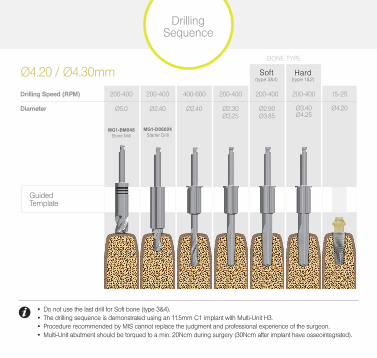
Ø4.20 / Ø4.30mm
Drilling Sequence
BONE TYPE
Guided Template
200-400
Ø5.0
MG1-BM048 Bone Mill
200-400
Ø2.40
MG1-D06024 Starter Drill
400-600
Ø2.40
200-400
Ø2.30Ø3.25
200-400
Ø2.90Ø3.85
200-400
Ø3.40Ø4.25
15-25
Ø4.20
Drilling Speed (RPM)
Diameter
(type 1&2)(type 3&4)Soft Hard

• Do not use the last drill for Soft bone (type 3&4). • The drilling sequence is demonstrated using an 11.5mm C1 implant with Multi-Unit H3. • Procedure recommended by MIS cannot replace the judgment and professional experience of the surgeon. • Multi-Unit abutment should be torqued to a min. 20Ncm during surgery (30Ncm after implant have osseointegrated).
• Do not use the last drill for Soft bone (type 3&4). • The drilling sequence is demonstrated using an 11.5mm C1 implant with Multi-Unit H3. • Procedure recommended by MIS cannot replace the judgment and professional experience of the surgeon. • Multi-Unit abutment should be torqued to a min. 20Ncm during surgery (30Ncm after implant have osseointegrated).
Ø5mm
Drilling Speed (RPM)
Drilling Sequence
BONE TYPE
Guided Template
400-600
Ø2.40
200-400
Ø2.30Ø3.25
200-400
Ø2.90Ø3.85
Diameter
200-400
Ø5.0
MG1-BM048 Bone Mill
200-400
Ø3.40Ø4.25
200-400
Ø3.90Ø4.95
15-25
Ø5
200-400
Ø2.40
MG1-D06024 Starter Drill
(type 3&4)Soft
(type 1&2)Hard

Bone Mill Laser MarksBone mill tool has built-in laser marks for depth control. Each line represents a Multi-Unit height. (For Multi-Unit abutment H=1mm, drill until the middle of the first line).
The bone mill is designed to flatten the alveolar ridge, when needed, prior to drilling. It enables better drilling accuracy in sharp alveolar ridges. In addition it allows an easy path of insertion for the Multi-Unit abutment.
Bone Mill
BA
500rpm. max.
Use of a bone mill should be part of the planning stage.

Starter DrillThe starter drill MG1-D06024 is the first drill in the procedure and has two main functions:
• Creating a centered hole for subsequent drills. • Determining the bone density.
Pilot DrillThe pilot drill is the second drill used in the procedure. The main function is to deepen the osteotomy to the correct depth.
Starter Drill & Pilot Drill
Use of a bone mill should be part of the planning stage.
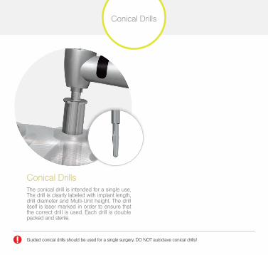
Conical DrillsThe conical drill is intended for a single use. The drill is clearly labeled with implant length, drill diameter and Multi-Unit height. The drill itself is laser marked in order to ensure that the correct drill is used. Each drill is double packed and sterile.
Conical Drills
Guided conical drills should be used for a single surgery. DO NOT autoclave conical drills!

Assembly of Multi-Unit to Insertion ToolThe Direct Insertion Tool MG1-INSDR1, is used to secure the template into the placed implant. After removal of the Multi-Unit grip handle, connect the designated insertion tool to the Multi-Unit abutment, tighten by hand.
Assembly of Insertion Tool to ImplantThe Direct Insertion Tool should be attached to the implant manually prior to implant placement. Open implant inner tube and screw the mounted insertion tool (attached to the Multi-Unit) into the implant, tighten by hand.
BA
Insertion Tool Assembly
Multi-Unit abutments are double packed and sterile.
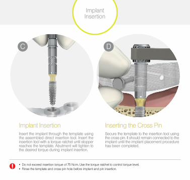
Implant InsertionInsert the implant through the template using the assembled direct insertion tool. Insert the insertion tool with a torque ratchet until stopper reaches the template. Abutment will tighten to the desired torque during implant insertion.
Secure the template to the insertion tool using the cross pin. It should remain connected to the implant until the implant placement procedure has been completed.
Inserting the Cross Pin
• Do not exceed insertion torque of 75 Ncm. Use the torque ratchet to control torque level. • Rinse the template and cross pin hole before implant and pin insertion.
C D
Implant Insertion
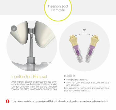
After implant placement procedure has been completed, remove the insertion tool by removing its internal screw. Then remove the template, together with all the insertion tools and cross pins.
In cases of:
• Non parallel implants. • Insertion path deviation between template
and implants.First remove the fixation pins and insertion tools, then remove the template.
Insertion Tool Removal^
^
α°E
Insertion Tool Removal
If clamping occurs between insertion tool and Multi-Unit, release by gently applying reverse torque to the insertion tool.
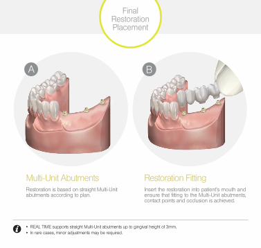
Multi-Unit AbutmentsRestoration is based on straight Multi-Unit abutments according to plan.
Insert the restoration into patient’s mouth and ensure that fitting to the Multi-Unit abutments, contact points and occlusion is achieved.
Restoration Fitting
BA
Final Restoration Placement
• REAL TIME supports straight Multi-Unit abutments up to gingival height of 3mm. • In rare cases, minor adjustments may be required.
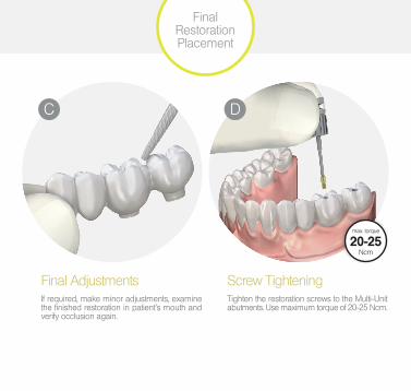
Final AdjustmentsTighten the restoration screws to the Multi-Unit abutments. Use maximum torque of 20-25 Ncm.
If required, make minor adjustments, examine the finished restoration in patient’s mouth and verify occlusion again.
Screw Tightening
C
Final Restoration Placement
D
max. torque
20-25Ncm
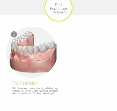
Final RestorationFill in the screw channel opening with blocking material (e.g Teflon, Cotton rolls) and complete with composite resin. Verify occlusion again.
Final Restoration Placement
E
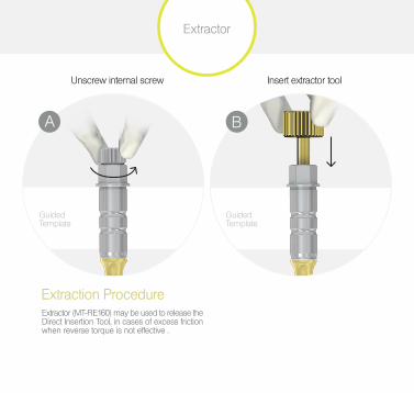
Extraction Procedure
Extractor
Extractor (MT-RE160) may be used to release the Direct Insertion Tool, in cases of excess friction when reverse torque is not effective .
Unscrew internal screw Insert extractor tool
A
Guided Template
B
Guided Template
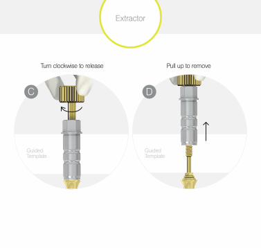
Turn clockwise to release Pull up to remove
Extractor
D
Guided Template
C
Guided Template

MIS Implants Technologies Ltd.P.O.Box 7, Bar Lev Industrial Park, 2015600, IsraelWebsite: www.mis-implants.com
MIS Implants Technologies GmbHSimeonscarre 2, 32423 Minden, GermanyTel: +49 571-972-7620Email: [email protected]
The MIS Quality System and Modern Lab systems
comply with the following international quality standards:
ISO 13485:2003 – Quality Management System
for Medical Devices and ISO 9001: 2008 – Quality
Management System. In addition, the MIS Quality
System complies with Medical Device Directive
93/42/EEC. Please note that not all products are
registered or available in every country or region.
© MIS Implant s Technologies Ltd. Al l Rights Reserved.
MP-MG101 Rev.2
&powered by:
Developed by DDS Renaat De Clerck