Embed Size (px)
Citation preview
High-Efficiency, Medium-Voltage-Input, Solid-State-Transformer-Based 400-kW/1000-V/400-A Extreme Fast Charger for Electric Vehicles
DE-EE0008361
Dr. Charles Zhu, Principal InvestigatorDelta Electronics (Americas) LtdJune 13, 2019
ELT241
2
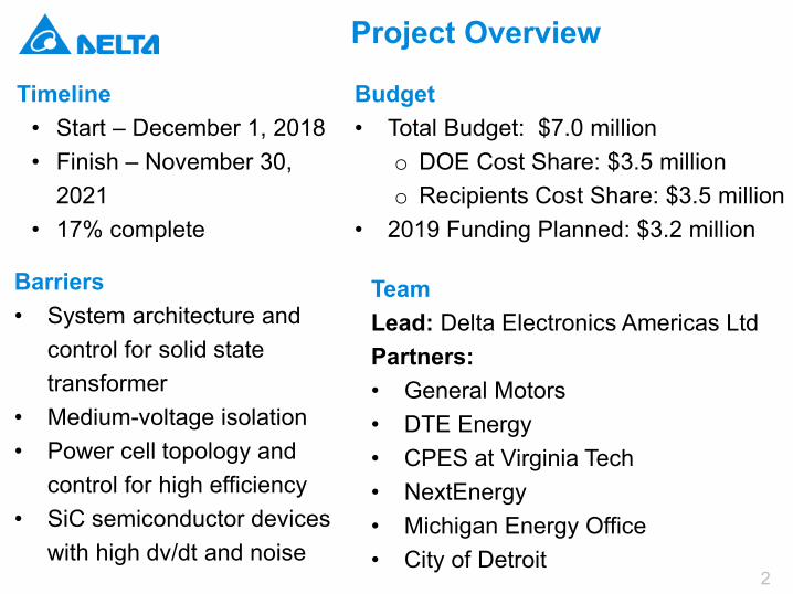
Project Overview
Timeline• Start – December 1, 2018• Finish – November 30,
2021• 17% complete
Budget• Total Budget: $7.0 million
o DOE Cost Share: $3.5 milliono Recipients Cost Share: $3.5 million
• 2019 Funding Planned: $3.2 million
Barriers• System architecture and
control for solid state transformer
• Medium-voltage isolation• Power cell topology and
control for high efficiency• SiC semiconductor devices
with high dv/dt and noise
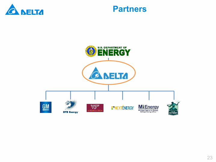
TeamLead: Delta Electronics Americas LtdPartners:• General Motors• DTE Energy• CPES at Virginia Tech • NextEnergy• Michigan Energy Office• City of Detroit
3
Relevance Project Objectives
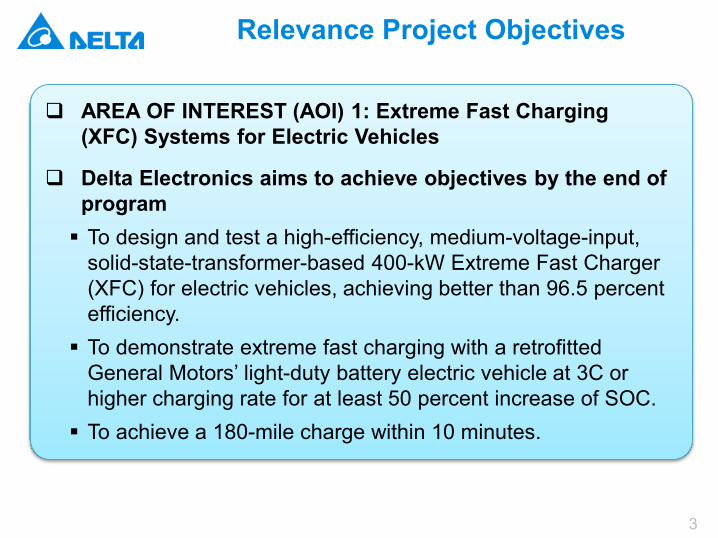
AREA OF INTEREST (AOI) 1: Extreme Fast Charging (XFC) Systems for Electric Vehicles
Delta Electronics aims to achieve objectives by the end of program To design and test a high-efficiency, medium-voltage-input,
solid-state-transformer-based 400-kW Extreme Fast Charger (XFC) for electric vehicles, achieving better than 96.5 percent efficiency. To demonstrate extreme fast charging with a retrofitted
General Motors’ light-duty battery electric vehicle at 3C or higher charging rate for at least 50 percent increase of SOC. To achieve a 180-mile charge within 10 minutes.
4
Budget Period 1 Milestones
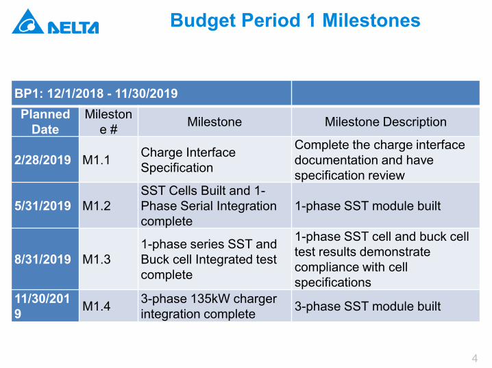
BP1: 12/1/2018 - 11/30/2019Planned
DateMileston
e # Milestone Milestone Description
2/28/2019 M1.1 Charge Interface Specification
Complete the charge interface documentation and have specification review
5/31/2019 M1.2SST Cells Built and 1-Phase Serial Integration complete
1-phase SST module built
8/31/2019 M1.31-phase series SST and Buck cell Integrated test complete
1-phase SST cell and buck cell test results demonstrate compliance with cell specifications
11/30/2019 M1.4 3-phase 135kW charger
integration complete 3-phase SST module built
5
Approaches
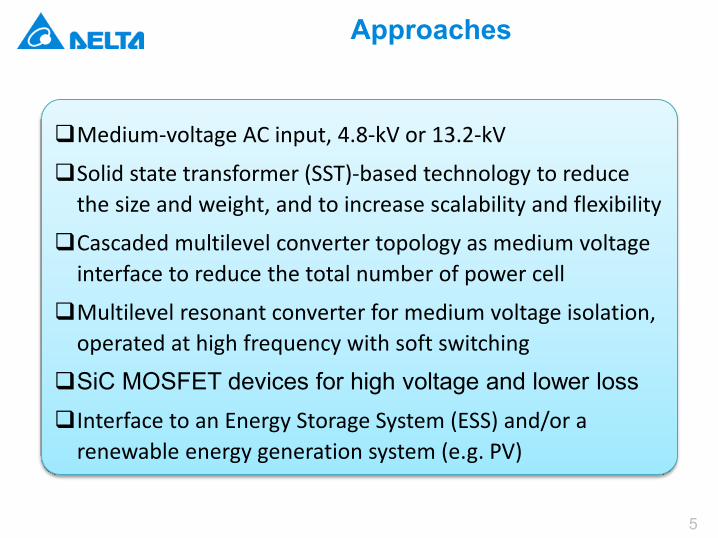
Medium-voltage AC input, 4.8-kV or 13.2-kV
Solid state transformer (SST)-based technology to reduce the size and weight, and to increase scalability and flexibility
Cascaded multilevel converter topology as medium voltage interface to reduce the total number of power cell
Multilevel resonant converter for medium voltage isolation, operated at high frequency with soft switching
SiC MOSFET devices for high voltage and lower lossInterface to an Energy Storage System (ESS) and/or a
renewable energy generation system (e.g. PV)
6
Conventional DC Fast Charger Solution
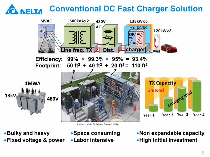
Efficiency: 99% × 99.3% × 95% = 93.4%Footprint: 50 ft2 + 40 ft2 + 20 ft2 = 110 ft2
•Non expandable capacity•High initial investment
•Bulky and heavy•Fixed voltage & power
Line freq. TX×
Dist.=~
3Φ ==
PFC DC/DC
charger
MVAC 480V AC
120kW×8
135kW×6500kVA×2
Year 1 Year 2 Year 3 Year 4
unusedTX Capacity
Installation site for Tesla Super Charger in U.S.A
13kV 480V
1MWA
•Space consuming •Labor intensive
7
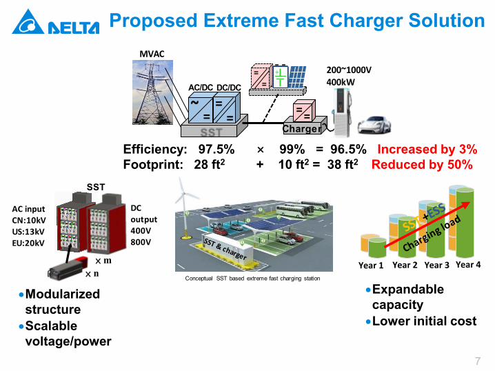
Proposed Extreme Fast Charger Solution
Efficiency: 97.5% × 99% = 96.5% Increased by 3% Footprint: 28 ft2 + 10 ft2 = 38 ft2 Reduced by 50%
•Modularized structure•Scalable voltage/power
•Expandable capacity•Lower initial cost
MVAC
===
~AC/DC DC/DC
==Charger
==
+
200~1000V400kW
Year 1 Year 2 Year 3 Year 4
SST
× n× m
AC inputCN:10kVUS:13kVEU:20kV
DC output400V800V
Conceptual SST based extreme fast charging station
8
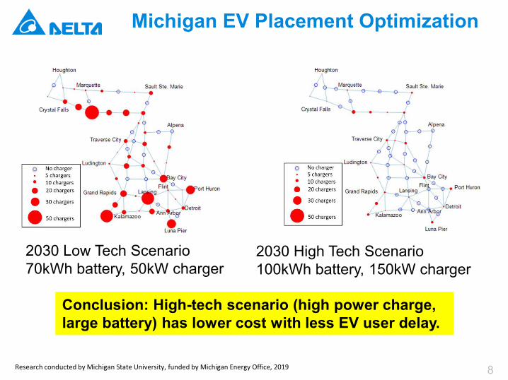
Michigan EV Placement Optimization
Research conducted by Michigan State University, funded by Michigan Energy Office, 2019
2030 Low Tech Scenario70kWh battery, 50kW charger
2030 High Tech Scenario100kWh battery, 150kW charger
Conclusion: High-tech scenario (high power charge, large battery) has lower cost with less EV user delay.
9
Technical Progress
10
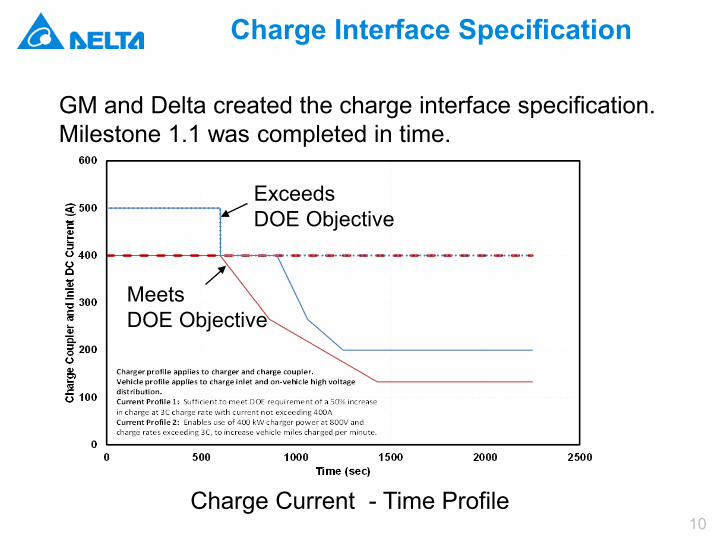
Charge Interface Specification
GM and Delta created the charge interface specification. Milestone 1.1 was completed in time.
Charge Current - Time Profile
Meets DOE Objective
ExceedsDOE Objective
11
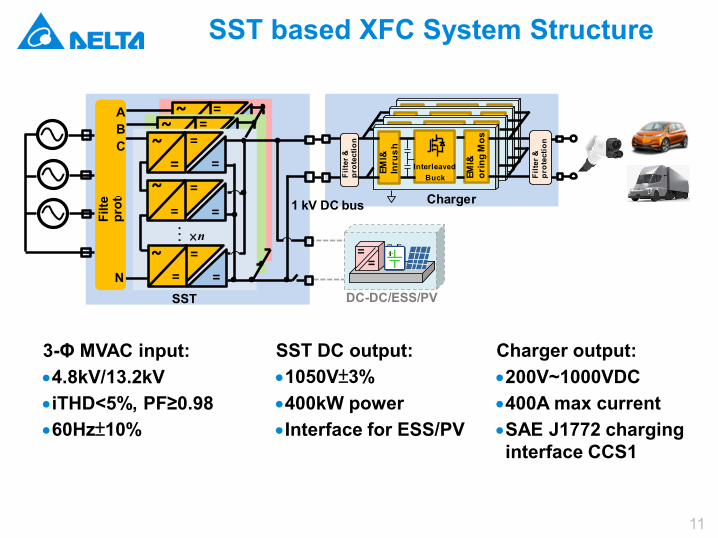
SST based XFC System Structure
=~
==
=~
==
=~
==
=~
==
=~
==
=~
==
=~
==
×n
=~
==
=~
==
…Filte
prot
e
SST
1 kV DC bus
DC-DC/ESS/PVN
==
A B C Interleave
dBuck
MCU
Com.
InterleavedBuck
MCU
Filte
r &
prot
ectio
n
EMI&
Inru
sh
InterleavedBuck EM
I&or
ing
Mos
Filte
r &
prot
ectio
n
Charger
3-Φ MVAC input:•4.8kV/13.2kV•iTHD<5%, PF≥0.98•60Hz±10%
SST DC output:•1050V±3%•400kW power•Interface for ESS/PV
Charger output:•200V~1000VDC•400A max current•SAE J1772 charging interface CCS1
12
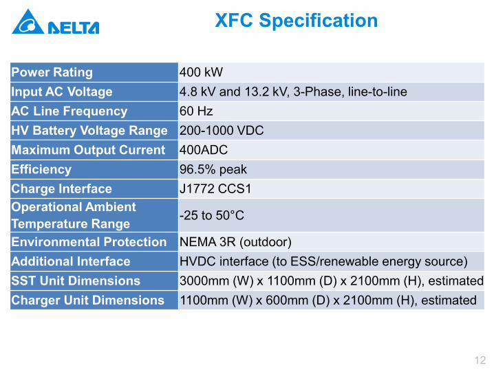
XFC Specification
Power Rating 400 kWInput AC Voltage 4.8 kV and 13.2 kV, 3-Phase, line-to-lineAC Line Frequency 60 HzHV Battery Voltage Range 200-1000 VDCMaximum Output Current 400ADCEfficiency 96.5% peakCharge Interface J1772 CCS1Operational Ambient Temperature Range -25 to 50°C
Environmental Protection NEMA 3R (outdoor)Additional Interface HVDC interface (to ESS/renewable energy source)SST Unit Dimensions 3000mm (W) x 1100mm (D) x 2100mm (H), estimatedCharger Unit Dimensions 1100mm (W) x 600mm (D) x 2100mm (H), estimated
13
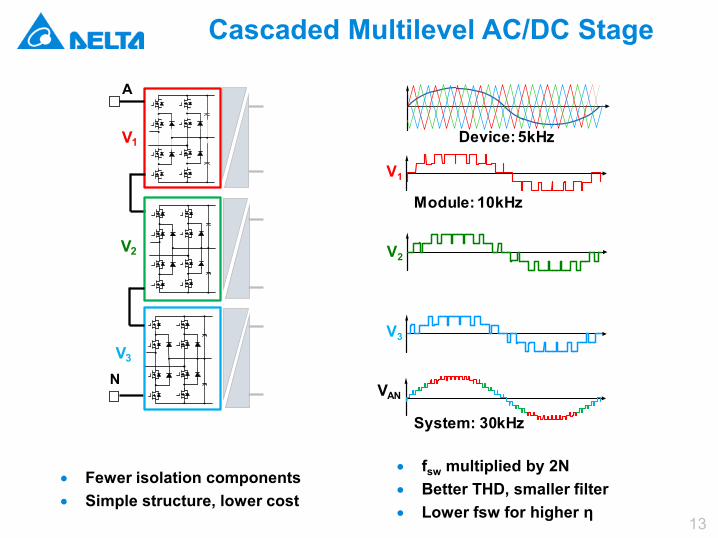
Cascaded Multilevel AC/DC Stage
N
A
V3
V2
V1
• Fewer isolation components• Simple structure, lower cost
Device: 5kHz
VAN
System: 30kHz
Module: 10kHz
V3
V2
V1
• fsw multiplied by 2N• Better THD, smaller filter• Lower fsw for higher η
14
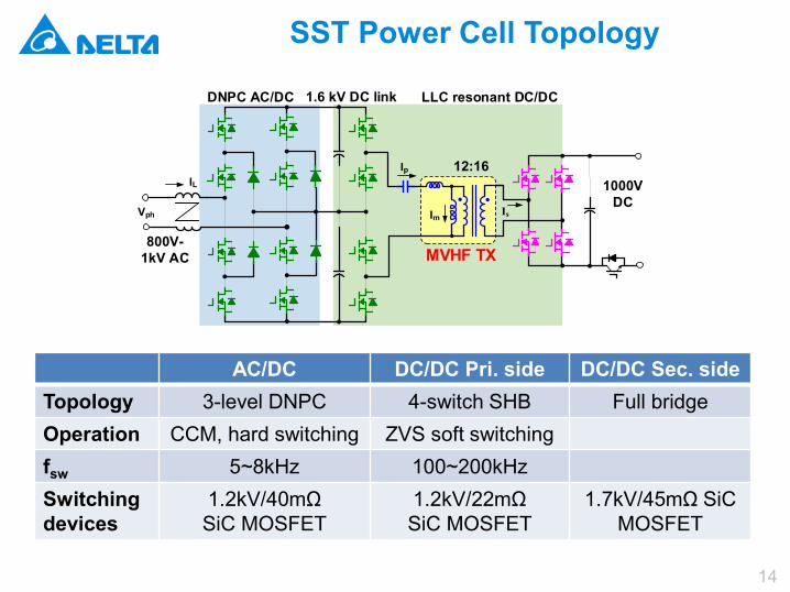
SST Power Cell Topology
AC/DC DC/DC Pri. side DC/DC Sec. sideTopology 3-level DNPC 4-switch SHB Full bridgeOperation CCM, hard switching ZVS soft switchingfsw 5~8kHz 100~200kHzSwitching devices
1.2kV/40mΩSiC MOSFET
1.2kV/22mΩSiC MOSFET
1.7kV/45mΩ SiC MOSFET
800V-1kV AC
1.6 kV DC link
1000V DC
MVHF TX
DNPC AC/DC LLC resonant DC/DC
Vph
Ip
Im Is
IL12:16
15
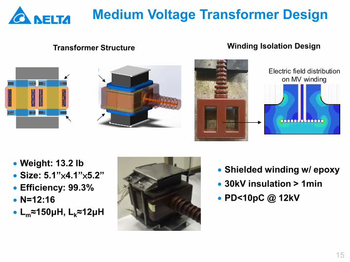
Medium Voltage Transformer Design
Transformer Structure Winding Isolation Design
ng in
g
Electric field distribution on MV winding
• Weight: 13.2 lb• Size: 5.1”×4.1”×5.2”• Efficiency: 99.3%• N=12:16• Lm≈150μH, Lk≈12μH
• Shielded winding w/ epoxy • 30kV insulation > 1min• PD<10pC @ 12kV
16
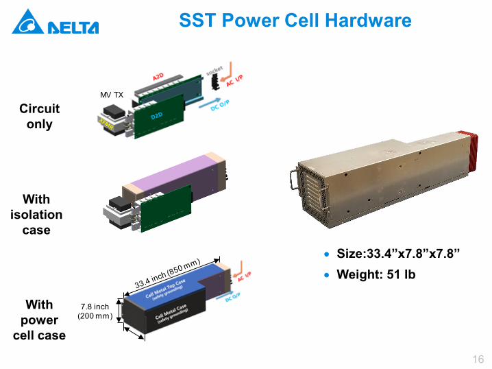
SST Power Cell Hardware
Circuit only
With isolation
case
With power
cell case
• Size:33.4”x7.8”x7.8”• Weight: 51 lb
MV TX
7.8 inch (200 mm)
17
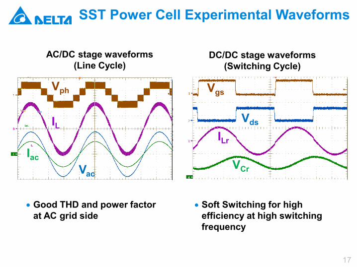
SST Power Cell Experimental Waveforms
• Good THD and power factor at AC grid side
• Soft Switching for high efficiency at high switching frequency
AC/DC stage waveforms (Line Cycle)
IacVac
IL
Vph
VCr
Vds
ILr
Vgs
DC/DC stage waveforms (Switching Cycle)
18
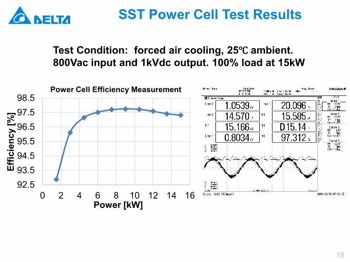
SST Power Cell Test Results
92.593.594.595.596.597.598.5
0 2 4 6 8 10 12 14 16
Effic
ienc
y [%
]
Power [kW]
Power Cell Efficiency Measurement
Test Condition: forced air cooling, 25℃ ambient. 800Vac input and 1kVdc output. 100% load at 15kW
19
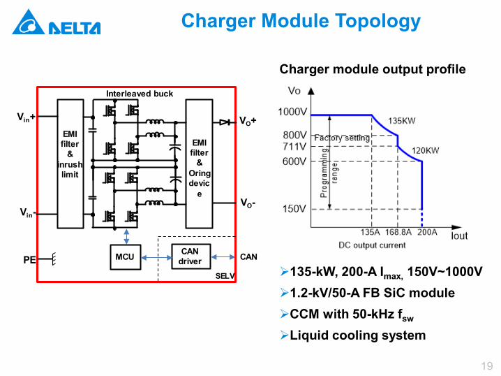
Charger Module Topology
EMIfilter
&inrushlimit
EMIfilter
& Oringdevic
e
Vin+
Vin-
VO+
VO-
Interleaved buck
MCU CAN driver
SELV
CANPE
Charger module output profile
135-kW, 200-A Imax, 150V~1000V1.2-kV/50-A FB SiC moduleCCM with 50-kHz fsw
Liquid cooling system
20
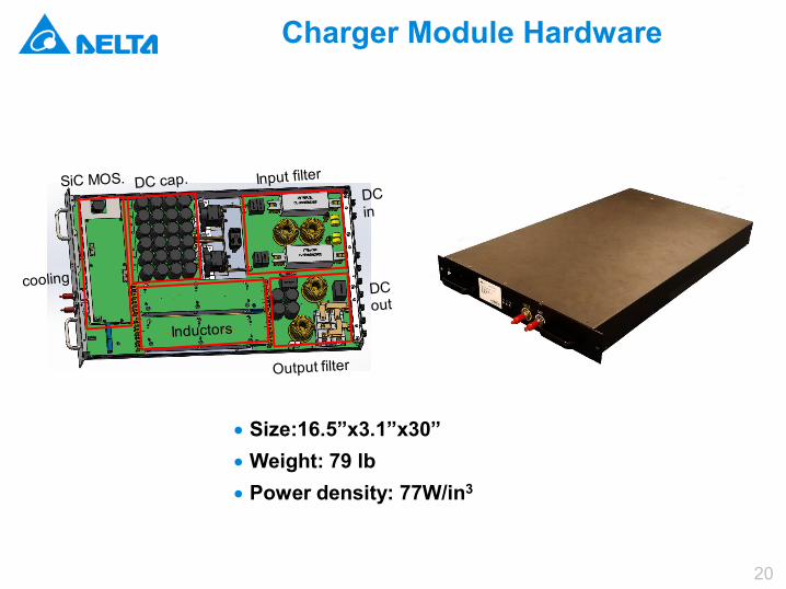
Charger Module Hardware
• Size:16.5”x3.1”x30”• Weight: 79 lb• Power density: 77W/in3
21
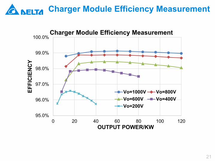
Charger Module Efficiency Measurement
95.0%
96.0%
97.0%
98.0%
99.0%
100.0%
0 20 40 60 80 100 120
EFFI
CIE
NC
Y
OUTPUT POWER/KW
Charger Module Efficiency Measurement
Vo=1000V Vo=800VVo=600V Vo=400VVo=200V
22
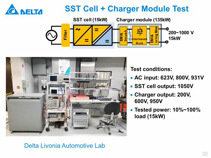
SST Cell + Charger Module Test
Test conditions:• AC input: 623V, 800V, 931V• SST cell output: 1050V• Charger output: 200V,
600V, 950V• Tested power: 10%~100%
load (15kW)
=~
==
200~1000 V15kWEM
I&In
rush
InterleavedBuck EM
I&or
ing
Mos
Filte
r
SST cell (15kW) Charger module (135kW)
Delta Livonia Automotive Lab
23
Partners
24
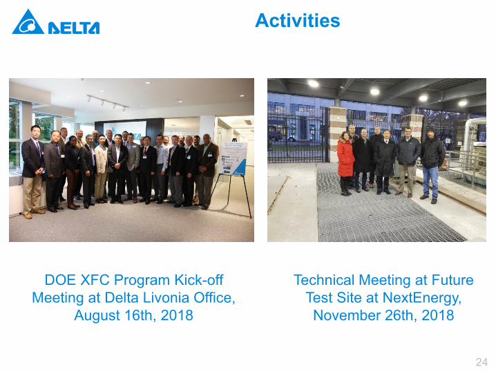
Activities
Technical Meeting at Future Test Site at NextEnergy, November 26th, 2018
DOE XFC Program Kick-off Meeting at Delta Livonia Office,
August 16th, 2018
25
Proposed Future Works
• Remainder of FY 2019• Test 1-phase 45kW charger integrated.• Build 3-phase 135kW charger.
• FY 2020• Test vehicle HVDS/RESS.• Test integrated 3-phase 135kW charger.• Test 4.8kV XFC system in lab.
• FY 2021• Build test vehicle.• Test 4.8kV XFC charging test with vehicle.• Test 13.2kV XFC charging test with vehicle.

Smarter. Greener. Together.
To learn more about Delta, please visit www.deltaww.comor scan the QR code
English Traditional
Chinese
Simplified Chinese