Embed Size (px)
Citation preview

High-Efficiency, Medium-Voltage
Input, Solid-State, Transformer-
Based 400-kW/1000-V/400-A Extreme
Fast Charger for Electric Vehicles
DE-EE0008361
Dr. Charles Zhu, Principal Investigator
Delta Electronics (Americas) Ltd
June, 2021
ELT241
“This presentation does not contain any proprietary,
confidential, or otherwise restricted information”
2
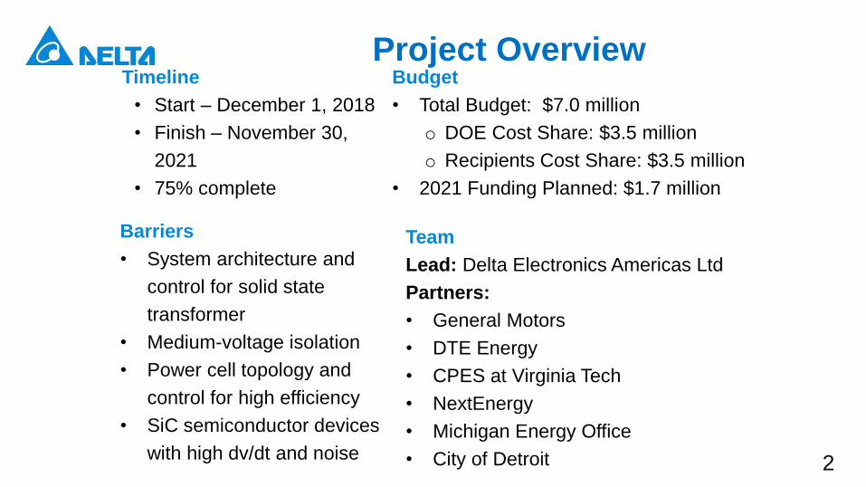
Project OverviewTimeline
• Start – December 1, 2018
• Finish – November 30,
2021
• 75% complete
Budget
• Total Budget: $7.0 million
o DOE Cost Share: $3.5 million
o Recipients Cost Share: $3.5 million
• 2021 Funding Planned: $1.7 million
Barriers
• System architecture and
control for solid state
transformer
• Medium-voltage isolation
• Power cell topology and
control for high efficiency
• SiC semiconductor devices
with high dv/dt and noise
Team
Lead: Delta Electronics Americas Ltd
Partners:
• General Motors
• DTE Energy
• CPES at Virginia Tech
• NextEnergy
• Michigan Energy Office
• City of Detroit
3
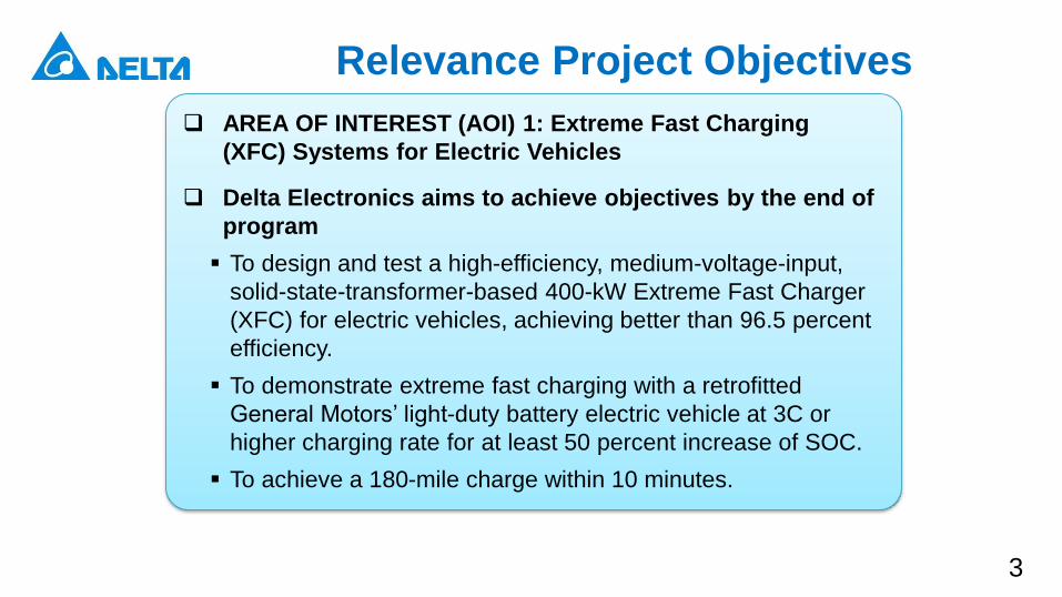
Relevance Project Objectives
AREA OF INTEREST (AOI) 1: Extreme Fast Charging
(XFC) Systems for Electric Vehicles
Delta Electronics aims to achieve objectives by the end of
program
To design and test a high-efficiency, medium-voltage-input,
solid-state-transformer-based 400-kW Extreme Fast Charger
(XFC) for electric vehicles, achieving better than 96.5 percent
efficiency.
To demonstrate extreme fast charging with a retrofitted
General Motors’ light-duty battery electric vehicle at 3C or
higher charging rate for at least 50 percent increase of SOC.
To achieve a 180-mile charge within 10 minutes.
4
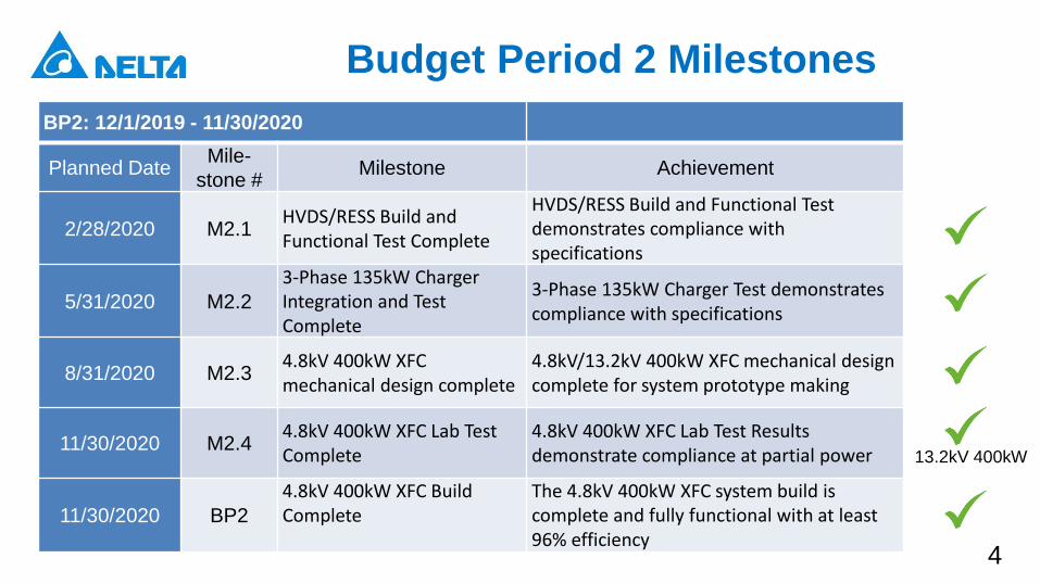
Budget Period 2 Milestones
BP2: 12/1/2019 - 11/30/2020
Planned DateMile-
stone #Milestone Achievement
2/28/2020 M2.1HVDS/RESS Build and Functional Test Complete
HVDS/RESS Build and Functional Test demonstrates compliance with specifications
5/31/2020 M2.2
3-Phase 135kW Charger Integration and Test Complete
3-Phase 135kW Charger Test demonstrates compliance with specifications
8/31/2020 M2.34.8kV 400kW XFC mechanical design complete
4.8kV/13.2kV 400kW XFC mechanical design complete for system prototype making
11/30/2020 M2.44.8kV 400kW XFC Lab Test Complete
4.8kV 400kW XFC Lab Test Results demonstrate compliance at partial power
11/30/2020 BP2
4.8kV 400kW XFC Build Complete
The 4.8kV 400kW XFC system build is complete and fully functional with at least 96% efficiency
13.2kV 400kW
5
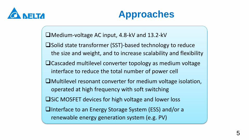
Approaches
Medium-voltage AC input, 4.8-kV and 13.2-kV
Solid state transformer (SST)-based technology to reduce
the size and weight, and to increase scalability and flexibility
Cascaded multilevel converter topology as medium voltage
interface to reduce the total number of power cell
Multilevel resonant converter for medium voltage isolation,
operated at high frequency with soft switching
SiC MOSFET devices for high voltage and lower loss
Interface to an Energy Storage System (ESS) and/or a
renewable energy generation system (e.g. PV)
6
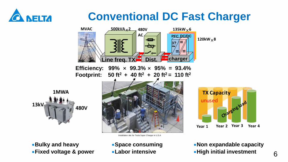
Conventional DC Fast Charger
Efficiency: 99% × 99.3% × 95% = 93.4%
Footprint: 50 ft2 + 40 ft2 + 20 ft2 = 110 ft2
Non expandable capacity
High initial investment
Bulky and heavy
Fixed voltage & power
Year 1 Year 2 Year 3 Year 4
unused
TX Capacity
Installation site for Tesla Super Charger in U.S.A
13kV480V
1MWA
Space consuming
Labor intensive
Line freq. TX
×
Dist.
=~3? =
=
PFC DC/DC
charger
MVAC 480V
AC120kW×8
135kW×6500kVA ×2
7
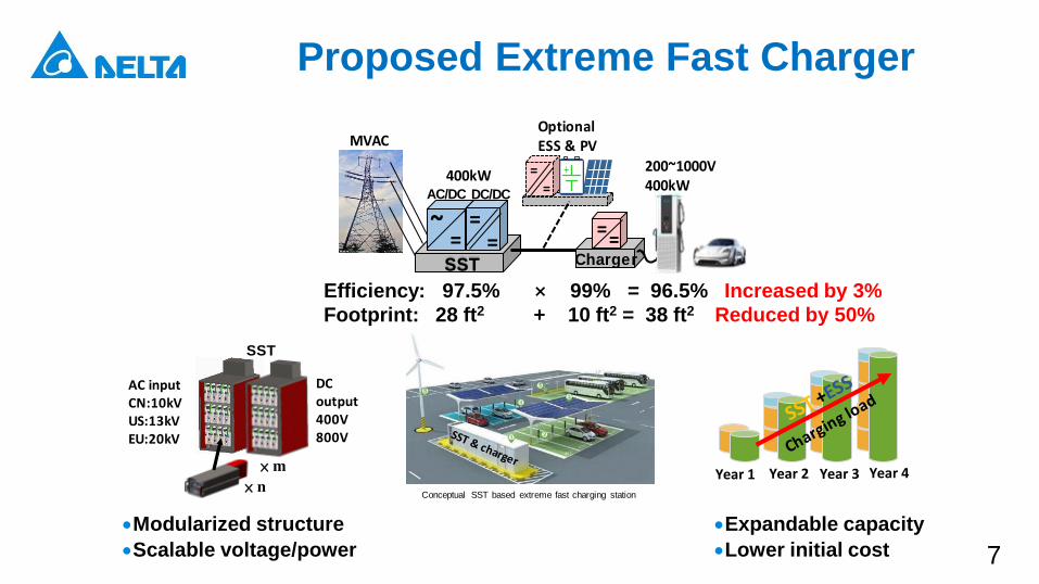
Proposed Extreme Fast Charger
Efficiency: 97.5% × 99% = 96.5% Increased by 3%
Footprint: 28 ft2 + 10 ft2 = 38 ft2 Reduced by 50%
Modularized structure
Scalable voltage/power
Expandable capacity
Lower initial cost
MVAC
===
~AC/DC DC/DC
==Charger
==
+
Optional ESS & PV
200~1000V400kW
SST
400kW
Year 1 Year 2 Year 3 Year 4
SST
× n
× m
AC inputCN:10kVUS:13kVEU:20kV
DC output400V800V
Conceptual SST based extreme fast charging station
8
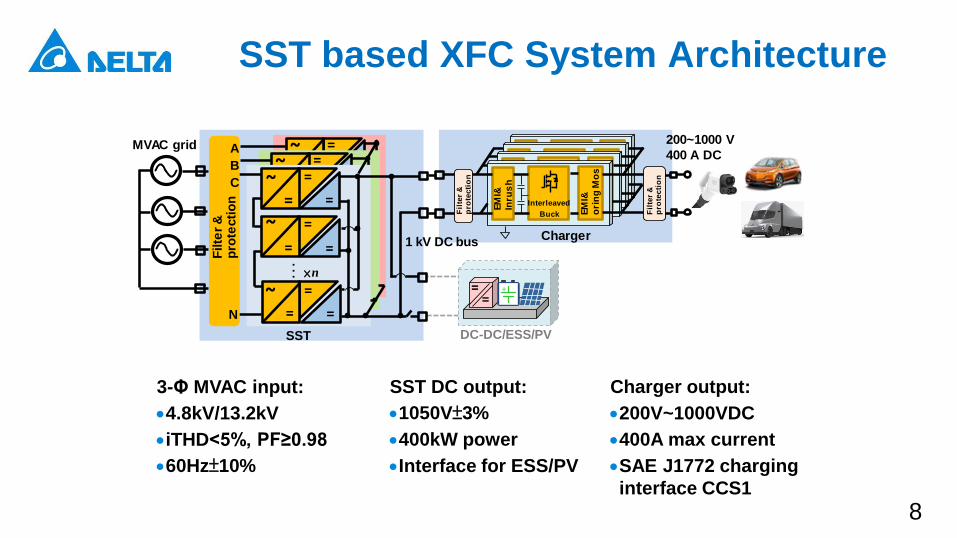
SST based XFC System Architecture
=~
=
=
=
~=
=
=
~=
=
=~
=
=
=
~=
=
=
~=
=
=~
=
=
×n
=
~=
=
=~
=
=
…Filte
r &
p
rote
cti
on
SST
MVAC grid
1 kV DC bus
200~1000 V
400 A DC
DC-DC/ESS/PV
N
==
+
A
B
C Interleave
d
Buck
MCU
Com
.
Interleave
d
Buck
MCU
Fil
ter
&
pro
tec
tio
n
EM
I&
Inru
sh
Interleaved
Buck EM
I&
ori
ng
Mo
s
Fil
ter
&
pro
tec
tio
n
Charger
3-Φ MVAC input:
4.8kV/13.2kV
iTHD<5%, PF≥0.98
60Hz±10%
SST DC output:
1050V±3%
400kW power
Interface for ESS/PV
Charger output:
200V~1000VDC
400A max current
SAE J1772 charging
interface CCS1
9
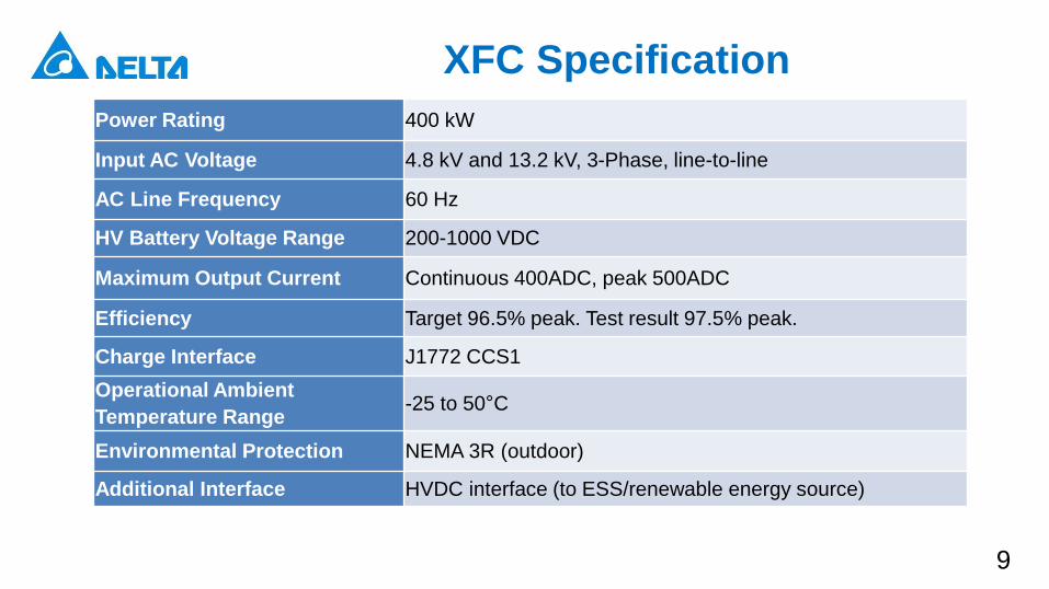
XFC Specification
Power Rating 400 kW
Input AC Voltage 4.8 kV and 13.2 kV, 3-Phase, line-to-line
AC Line Frequency 60 Hz
HV Battery Voltage Range 200-1000 VDC
Maximum Output Current Continuous 400ADC, peak 500ADC
Efficiency Target 96.5% peak. Test result 97.5% peak.
Charge Interface J1772 CCS1
Operational Ambient
Temperature Range-25 to 50°C
Environmental Protection NEMA 3R (outdoor)
Additional Interface HVDC interface (to ESS/renewable energy source)
10
Technical Progress
11
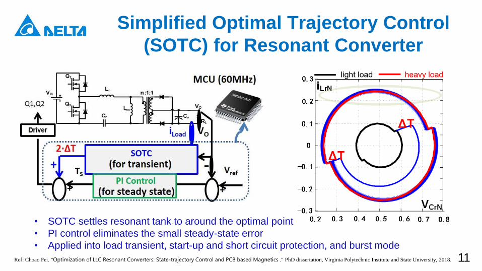
• SOTC settles resonant tank to around the optimal point
• PI control eliminates the small steady-state error
• Applied into load transient, start-up and short circuit protection, and burst mode
Ref: Choao Fei. "Optimization of LLC Resonant Converters: State-trajectory Control and PCB based Magnetics ." PhD dissertation, Virginia Polytechnic Institute and State University, 2018.
Simplified Optimal Trajectory Control
(SOTC) for Resonant Converter
12
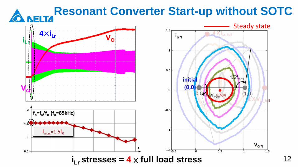
Resonant Converter Start-up without SOTCSteady state
iLr stresses = 4 × full load stress
13
0 t4ms1ms 2ms 3ms
Vo
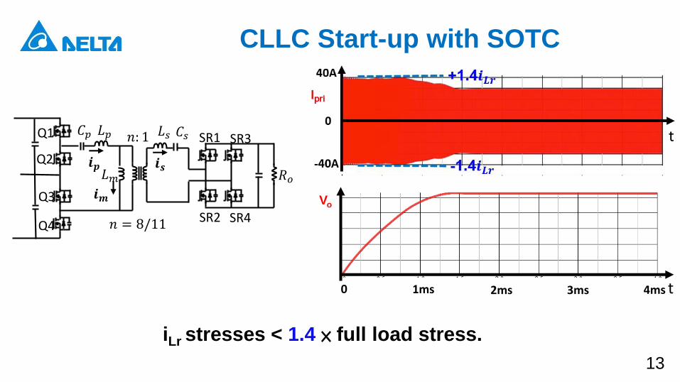
𝐿𝑝 𝐿𝑠
𝐿𝑚
𝐶𝑝Q1
Q2
SR1
SR2
SR3
SR4
𝒊𝒎Q3
Q4
𝐶𝑠𝑛: 1
𝒊𝒑 𝒊𝒔𝑅𝑜
𝑛 = 8/11
iLr stresses < 1.4 × full load stress.
CLLC Start-up with SOTC
14
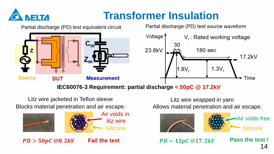
Partial discharge (PD) test equivalent circuit
IEC60076-3 Requirement: partial discharge < 50pC @ 17.2kV
Litz wire jacketed in Teflon sleeve
Blocks material penetration and air escape.
Litz wire wrapped in yarn
Allows material penetration and air escape.
Air voids in
litz wire
Silicone
Air voids free
Silicone
𝑷𝑫 > 𝟓𝟎𝒑𝑪@𝟖. 𝟐𝒌𝑽 𝑷𝑫 = 𝟏𝟐𝒑𝑪@𝟏𝟕. 𝟐𝒌𝑽Fail the test Pass the test !
Transformer Insulation
15
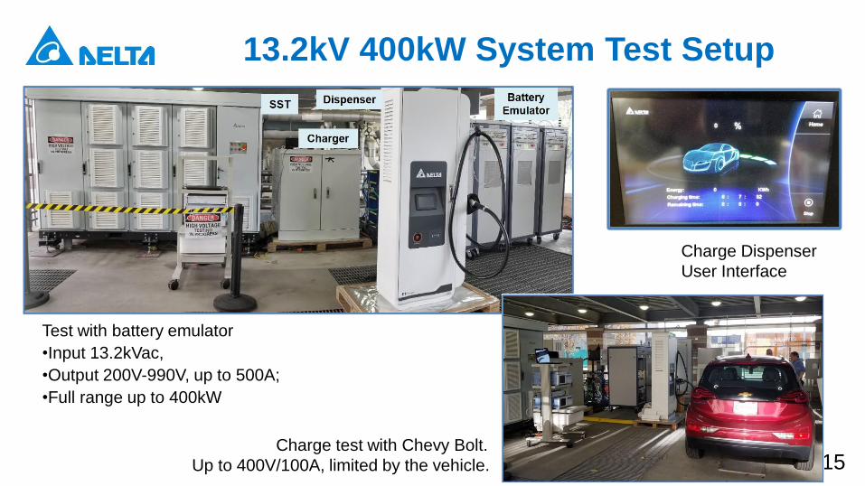
13.2kV 400kW System Test Setup
Test with battery emulator
•Input 13.2kVac,
•Output 200V-990V, up to 500A;
•Full range up to 400kW
Charge test with Chevy Bolt.
Up to 400V/100A, limited by the vehicle.
Charge Dispenser
User Interface
16
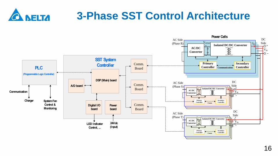
3-Phase SST Control Architecture
SST System
Controller
DSP (Main) board
Digital I/O
board
A/D board
Power
board
Comm.
Board
AC/DC
Converter
Primary
Controller
Secondary
Controller
+
Communication
AC Side
(Phase R)
DC
SideIsolated DC/DC Converter+
Vdclink
Vdc
Idc
Power Cells
Comm.
Board
Comm.
Board
AC/DC
Converter
Primary
Controller
Secondary
Controller
+
DC
SideIsolated DC/DC Converter+
Vdclink
Vdc
Idc
Comm.
AC/DC
Converter
Primary
Controller
Secondary
Controller
+
DC
SideIsolated DC/DC Converter+
Vdclink
Vdc
Idc
Comm.
AC Side
(Phase S)
AC Side
(Phase T)
24Vdc
(Input)LED Indicator
Control, ...
PLC
(Programmable Logic Controller)
Charger
Communication
System Fan
Control &
Monitoring
17
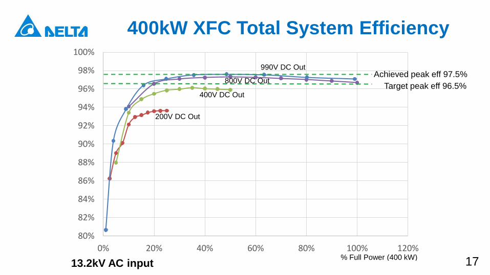
400kW XFC Total System Efficiency
80%
82%
84%
86%
88%
90%
92%
94%
96%
98%
100%
0% 20% 40% 60% 80% 100% 120%% Full Power (400 kW)
Target peak eff 96.5%
200V DC Out
990V DC Out
800V DC Out
400V DC Out
13.2kV AC input
Achieved peak eff 97.5%
18
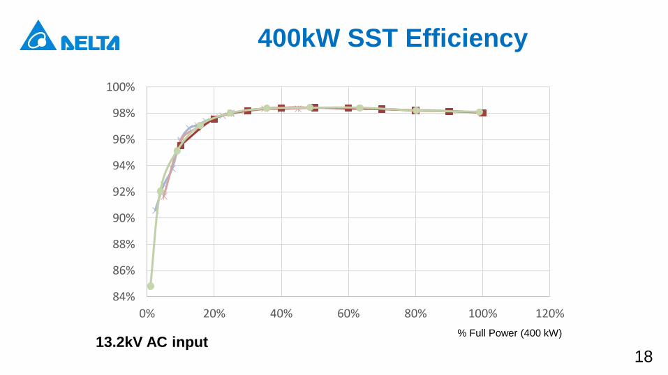
400kW SST Efficiency
13.2kV AC input
84%
86%
88%
90%
92%
94%
96%
98%
100%
0% 20% 40% 60% 80% 100% 120%
% Full Power (400 kW)
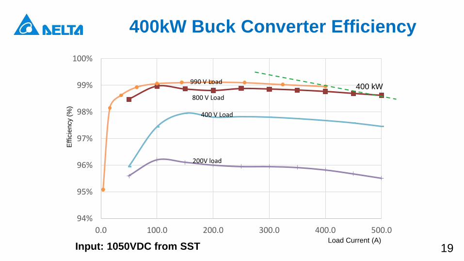
19Load Current (A)
Eff
icie
ncy (
%)
Input: 1050VDC from SST
94%
95%
96%
97%
98%
99%
100%
0.0 100.0 200.0 300.0 400.0 500.0
200V load
400 V Load
990 V Load
800 V Load
400 kW
400kW Buck Converter Efficiency
20
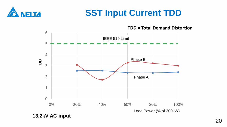
SST Input Current TDD
0
1
2
3
4
5
6
0% 20% 40% 60% 80% 100%
TDD = Total Demand Distortion
TD
D
Load Power (% of 200kW)
IEEE 519 Limit
Phase A
Phase B
13.2kV AC input
21
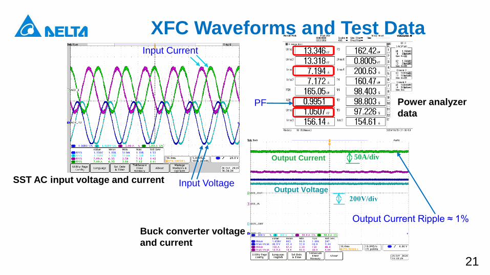
Input Voltage
Input Current
Output Voltage
Output Current 50A/div
Output Current Ripple ≈ 1%
PF
XFC Waveforms and Test Data
SST AC input voltage and current
Buck converter voltage
and current
Power analyzer
data
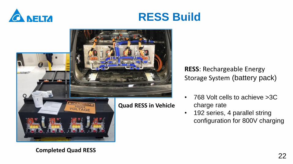
22Completed Quad RESS
RESS Build
• 768 Volt cells to achieve >3C
charge rate
• 192 series, 4 parallel string
configuration for 800V charging
RESS: Rechargeable Energy Storage System (battery pack)
Quad RESS in Vehicle
23
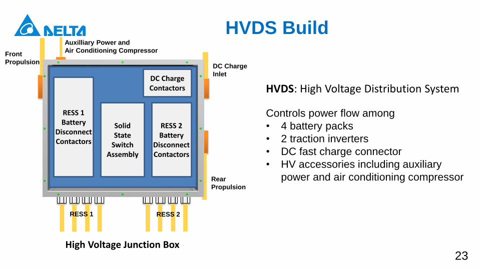
HVDS Build
High Voltage Junction Box
HVDS: High Voltage Distribution System
Controls power flow among
• 4 battery packs
• 2 traction inverters
• DC fast charge connector
• HV accessories including auxiliary
power and air conditioning compressor
RESS 1Battery
DisconnectContactors
RESS 2Battery
Disconnect Contactors
SolidState
SwitchAssembly
DC Charge Contactors
Auxilliary Power and
Air Conditioning CompressorFront
Propulsion
Rear
Propulsion
DC Charge
Inlet
RESS 1 RESS 2
24
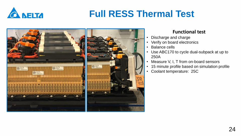
Full RESS Thermal Test
Functional test• Discharge and charge
• Verify on board electronics
• Balance cells
• Use ABC170 to cycle dual-subpack at up to
250A
• Measure V, I, T from on-board sensors
• 15 minute profile based on simulation profile
• Coolant temperature: 25C
25
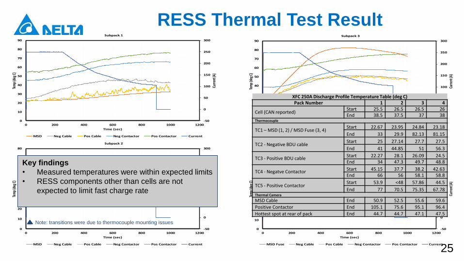
RESS Thermal Test Result
-50
0
50
100
150
200
250
300
0
10
20
30
40
50
60
70
80
90
0 200 400 600 800 1000 1200
Curr
ent (
A)
Tem
p (d
eg C
)
Time (sec)
Subpack 1
MSD Neg Cable Pos Cable Neg Contactor Pos Contactor Current
-50
0
50
100
150
200
250
300
0
10
20
30
40
50
60
70
80
0 200 400 600 800 1000 1200
Curr
ent (
A)
Tem
p (d
eg C
)
Time (sec)
Subpack 2
MSD Neg Cable Pos Cable Neg Contactor Pos Contactor Current
-50
0
50
100
150
200
250
300
0
10
20
30
40
50
60
70
80
90
0 200 400 600 800 1000 1200
Curr
ent (
A)
Tem
p (d
eg C
)
Time (sec)
Subpack 3
MSD Fuse Neg Cable Pos Cable Neg Contactor Pos Contactor Current
-50
0
50
100
150
200
250
300
0
10
20
30
40
50
60
70
80
90
0 200 400 600 800 1000 1200
Curr
ent (
A)
Tem
p (d
eg C
)
Time (sec)
Subpack 4
MSD Fuse Neg Cable Pos Cable Neg Contactor Pos Contactor Current
Note: transitions were due to thermocouple mounting issues
Key findings
• Measured temperatures were within expected limits
• RESS components other than cells are not
expected to limit fast charge rate
XFC 250A Discharge Profile Temperature Table (deg C)Pack Number 1 2 3 4
Cell (CAN reported)Start 25.5 26.5 26.5 26End 38.5 37.5 37 38
Thermocouple
TC1 – MSD (1, 2) / MSD Fuse (3, 4)Start 22.67 23.95 24.84 23.18
End 33 29.9 82.13 81.15
TC2 - Negative BDU cableStart 25 27.14 27.7 27.5
End 41 44.85 51 56.3
TC3 - Positive BDU cableStart 22.27 28.1 26.09 24.5End 34 47.3 49.7 48.8
TC4 - Negatve ContactorStart 45.15 37.7 38.2 42.63End 66 56 58.1 58.8
TC5 - Positive ContactorStart 53.9 <48 57.86 44.5
End 77 70.5 75.35 67.78Thermal Camera
MSD Cable End 50.9 52.5 55.6 59.6
Positive Contactor End 105.1 75.6 95.1 96.4
Hottest spot at rear of pack End 44.7 44.7 47.1 47.5
26
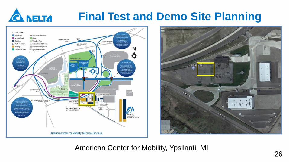
Final Test and Demo Site Planning
American Center for Mobility, Ypsilanti, MI

27
Final Test and Demo Site Planning
Site Plan Test Setup Electric Diagram
28
Collaboration and CoordinationDelta Electronics (Americas) Ltd. -Primary Recipient
• Administrative responsible to DOE, single point of contact.
• Technical direction and program management (timing, deliverables, budget).
• XFC prototypes development, testing, and system integration
• Commercialization.
General Motors
• Provide a retrofit BEV capable of XFC at 800-V or higher at 3C charging
CPES at Virginia Tech
• Conduct advanced research of power stage topology for the XFC.
• Conduct advanced research of the system level control for both AC/DC and DC/DC stages.
DTE Energy
• Contribute the use of a test facility for XFC testing, vehicle charging test and demonstration.
• Consult on grid impact and operation safety, voltage specifications, standards conformance and
certification.
NextEnergy
• Support XFC installation, integration, testing with battery emulator and EV, demonstration within
its medium-voltage Microgrid Power Pavilion Platform.
Michigan Energy Office
• Engage state-level public sector stakeholders supporting XFC deployment.
City of Detroit
• Strengthen coordination and fostering partnerships among business, neighborhood and
municipal departments.
29
Future Works
Remainder of FY 2021
• Test site construction and equipment installation.
• Build and verify retrofit vehicle.
• Test 400kW XFC system with Chevy Bolt.
• Test 400kW XFC system with retrofit vehicle.
• Final operation demonstration.

To learn more about Delta, please visit www.deltaww.com
or scan the QR code
English Tradition
al
Chinese
Simplified
Chinese
Smarter. Greener. Together.