Embed Size (px)
Citation preview
High Dynamic E-Motor-HiL-Testing: PC-based vs. FPGA l Dr. Wolfgang Eismann l ETAS-STV/MKT l 22. Juni 2010© ETAS GmbH 2009. All rights reserved. The names and designations used in this document are trademarks or brands belonging to their respective owners.
1
High Dynamic E-Motor-HiL-Testing: PC-based vs. FPGAOpen Technology Forum, 2010 Testing Expo Stuttgart, Germany, 22-06-2010
High Dynamic E-Motor-HiL-Testing: PC-based vs. FPGA l Dr. Wolfgang Eismann l ETAS-STV/MKT l 22. Juni 2010© ETAS GmbH 2009. All rights reserved. The names and designations used in this document are trademarks or brands belonging to their respective owners.
2
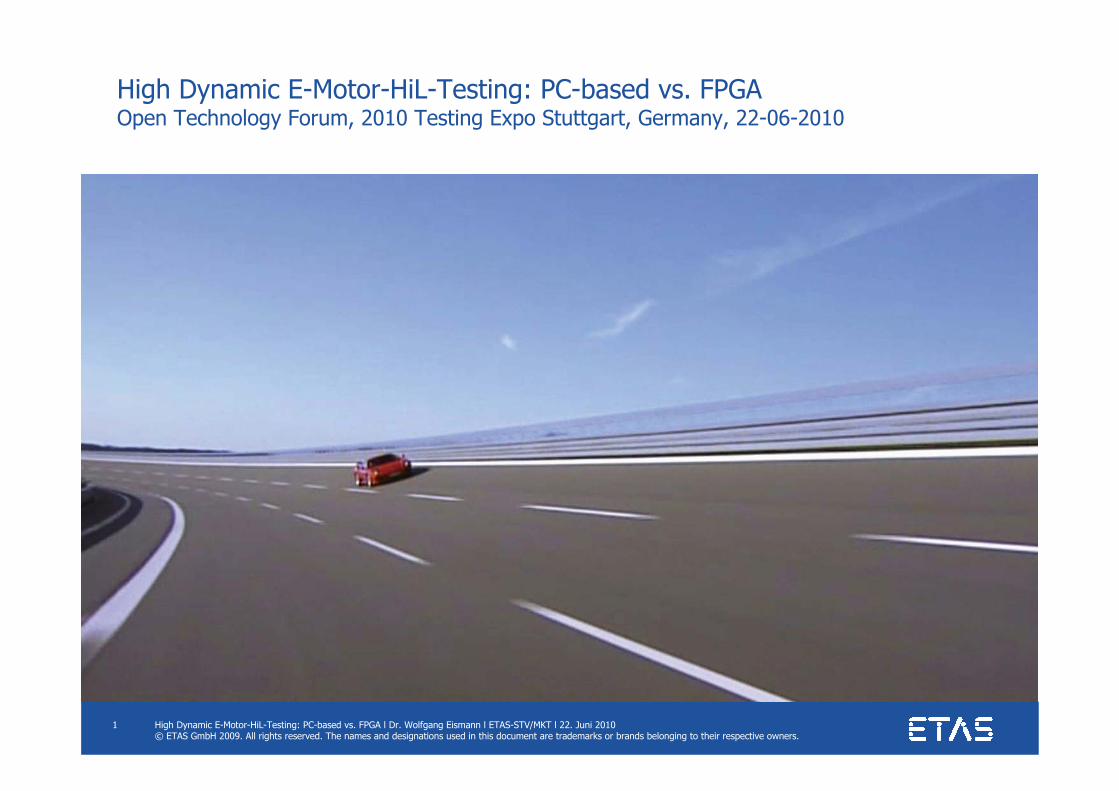
Challenges with HiL-testing of E-motor control in the lab
• Electric propulsion of passenger cars requirescontrol of power electronics in the range of 50 to >100 kW
• Typically, integrated housing of control unit and inverter(high electric power interfaces)
• Hence, HiL-testing needs handlingof electric power, that is significantlyhigher than in traditionalECU-HiL-applications(power-level HiL)
• Highly dynamic electro-magneticinverter-/E-motor system for electricpropulsion of passenger cars requires to computeupdate-frequency for control signals in the range of 10-25 kHz
• This is significantly higher update frequency compared to traditionalECU-HiL-applications in power-train or chassis control domain
Source: RealTimes - 1/2010
High Dynamic E-Motor-HiL-Testing: PC-based vs. FPGA l Dr. Wolfgang Eismann l ETAS-STV/MKT l 22. Juni 2010© ETAS GmbH 2009. All rights reserved. The names and designations used in this document are trademarks or brands belonging to their respective owners.
3
High dynamic E-motor HiL-testingAgenda
• Benefits of PC-based signal-level-HiL
• The need for low latency plant simulation
• Main advantages of FPGA-based model execution
• Switching between PC-based and FPGA
High Dynamic E-Motor-HiL-Testing: PC-based vs. FPGA l Dr. Wolfgang Eismann l ETAS-STV/MKT l 22. Juni 2010© ETAS GmbH 2009. All rights reserved. The names and designations used in this document are trademarks or brands belonging to their respective owners.
4
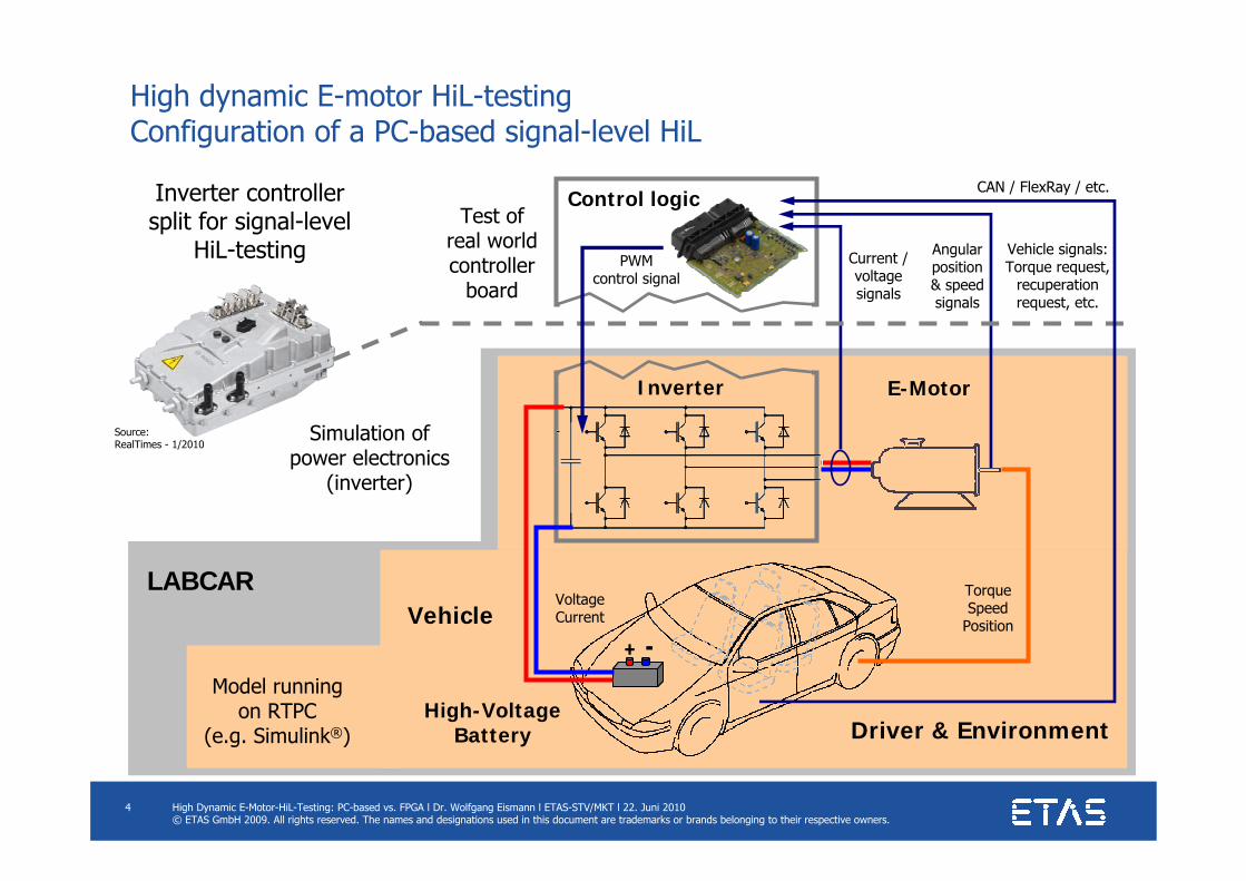
High dynamic E-motor HiL-testing Configuration of a PC-based signal-level HiL
Control logic
Inverter
Current /voltagesignals
Angularposition& speedsignals
TorqueSpeed
Position
E-Motor
High-VoltageBattery
Vehicle
Driver & Environment
Vehicle signals:Torque request,
recuperation request, etc.
CAN / FlexRay / etc.
LABCAR
--
+ --
+
Simulation ofpower electronics
(inverter)
Test ofreal worldcontroller
board
Inverter controllersplit for signal-level
HiL-testing PWMcontrol signal
Model runningon RTPC
(e.g. Simulink®)
VoltageCurrent
Source:RealTimes - 1/2010
High Dynamic E-Motor-HiL-Testing: PC-based vs. FPGA l Dr. Wolfgang Eismann l ETAS-STV/MKT l 22. Juni 2010© ETAS GmbH 2009. All rights reserved. The names and designations used in this document are trademarks or brands belonging to their respective owners.
5
High dynamic E-motor HiL-testing PC-based signal-level HiL
Configuration• Extract the control logic from integrated control/inverter housing• Interface on the level of inverter control signals and sensor signals• Replace E-motor and inverter power electronics by a model
Benefits of signal-level HiL++ Significantly lower cost for the test system compared to power-level HiL
(no need for high-voltage cabinet and management of high electric power)
Benefits of PC-based model execution++ Flexible PC-based execution of plant model (e.g. standard Simulink®-based)
+ No need for special (costly) VHDL-implementation of the model+ Almost unlimited compute power for high model granularity
Limitation― Test of power electronics hardware not covered― Risk of raster delay under certain conditions
(e.g. left-aligned control signal close to 100% DC)
High Dynamic E-Motor-HiL-Testing: PC-based vs. FPGA l Dr. Wolfgang Eismann l ETAS-STV/MKT l 22. Juni 2010© ETAS GmbH 2009. All rights reserved. The names and designations used in this document are trademarks or brands belonging to their respective owners.
6
High dynamic E-motor HiL-testingAgenda
• Benefits of PC-based signal-level-HiL
• The need for low latency plant simulation
• Main advantages of FPGA-based model execution
• Switching between PC-based and FPGA
High Dynamic E-Motor-HiL-Testing: PC-based vs. FPGA l Dr. Wolfgang Eismann l ETAS-STV/MKT l 22. Juni 2010© ETAS GmbH 2009. All rights reserved. The names and designations used in this document are trademarks or brands belonging to their respective owners.
7
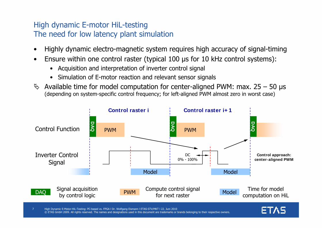
High dynamic E-motor HiL-testing The need for low latency plant simulation
Control approach:center-aligned PWM
DA
Q
PWM
Control raster i+1Control raster i
Inverter ControlSignal
DC0% - 100%
• Highly dynamic electro-magnetic system requires high accuracy of signal-timing• Ensure within one control raster (typical 100 µs for 10 kHz control systems):
• Acquisition and interpretation of inverter control signal• Simulation of E-motor reaction and relevant sensor signals
Available time for model computation for center-aligned PWM: max. 25 – 50 µs(depending on system-specific control frequency; for left-aligned PWM almost zero in worst case)
Control Function
Model
Model Time for modelcomputation on HiLDAQ Signal acquisition
by control logic PWM Compute control signalfor next raster
DA
Q
DA
Q
PWM
Model
High Dynamic E-Motor-HiL-Testing: PC-based vs. FPGA l Dr. Wolfgang Eismann l ETAS-STV/MKT l 22. Juni 2010© ETAS GmbH 2009. All rights reserved. The names and designations used in this document are trademarks or brands belonging to their respective owners.
8
High dynamic E-motor HiL-testingAgenda
• Benefits of PC-based signal-level-HiL
• The need for low latency plant simulation
• Main advantages of FPGA-based model execution
• Switching between PC-based and FPGA
High Dynamic E-Motor-HiL-Testing: PC-based vs. FPGA l Dr. Wolfgang Eismann l ETAS-STV/MKT l 22. Juni 2010© ETAS GmbH 2009. All rights reserved. The names and designations used in this document are trademarks or brands belonging to their respective owners.
9
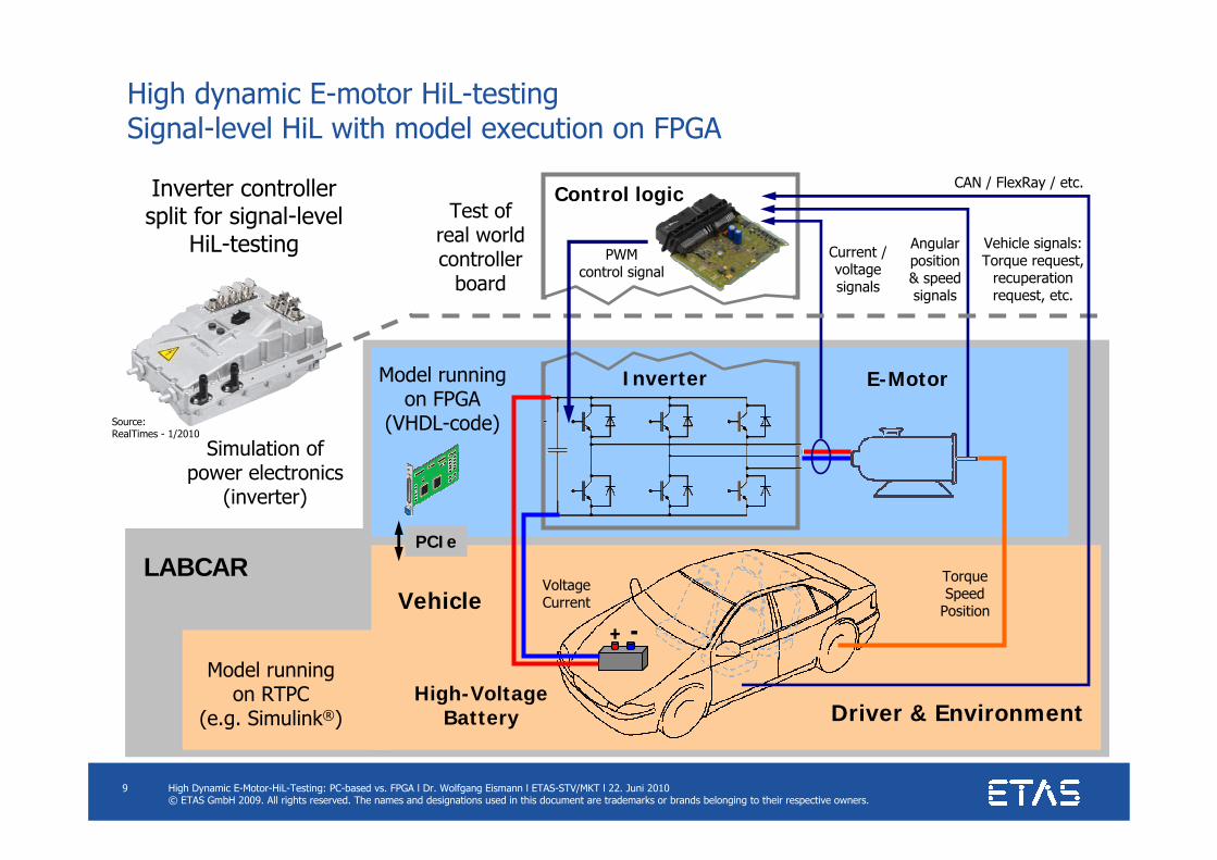
High dynamic E-motor HiL-testing Signal-level HiL with model execution on FPGA
Control logic
Inverter
Current /voltagesignals
Angularposition& speedsignals
TorqueSpeed
Position
E-Motor
High-VoltageBattery
Vehicle
Driver & Environment
Vehicle signals:Torque request,
recuperation request, etc.
CAN / FlexRay / etc.
LABCAR
--
+ --
+
Simulation ofpower electronics
(inverter)
Test ofreal worldcontroller
board
Inverter controllersplit for signal-level
HiL-testing PWMcontrol signal
Model runningon RTPC
(e.g. Simulink®)
VoltageCurrent
Model runningon FPGA
(VHDL-code)
PCIe
Source:RealTimes - 1/2010
High Dynamic E-Motor-HiL-Testing: PC-based vs. FPGA l Dr. Wolfgang Eismann l ETAS-STV/MKT l 22. Juni 2010© ETAS GmbH 2009. All rights reserved. The names and designations used in this document are trademarks or brands belonging to their respective owners.
10
High dynamic E-motor HiL-testing Model execution on FPGA
Configuration• Same hardware set-up as with RTPC-based signal-level HiL• Inverter and E-motor model is implemented in VHDL-code for FPGA• Model execution on-board the multi-I/O-board ES5340• PCIe-interface with vehicle/driver/environment modules running on RTPC
Main benefits of FPGA-based model execution++ Quasi-continuous plant simulation (model execution time ≤ 1 µs)
Simulation of inverter and E-motor directly following the control signalNo risk of raster delay (in typical HiL-applications)
+ Simulation of switching-ripples inherent
Limitation / remarkImplementation of reliable and efficient VHDL-code for FPGAneeds special expertise(even when applying FPGA-development framework for Simulink®)
High Dynamic E-Motor-HiL-Testing: PC-based vs. FPGA l Dr. Wolfgang Eismann l ETAS-STV/MKT l 22. Juni 2010© ETAS GmbH 2009. All rights reserved. The names and designations used in this document are trademarks or brands belonging to their respective owners.
11
High dynamic E-motor HiL-testingAgenda
• Benefits of PC-based signal-level-HiL
• The need for low latency plant simulation
• Main advantages of FPGA-based model execution
• Switching between PC-based and FPGA
High Dynamic E-Motor-HiL-Testing: PC-based vs. FPGA l Dr. Wolfgang Eismann l ETAS-STV/MKT l 22. Juni 2010© ETAS GmbH 2009. All rights reserved. The names and designations used in this document are trademarks or brands belonging to their respective owners.
12
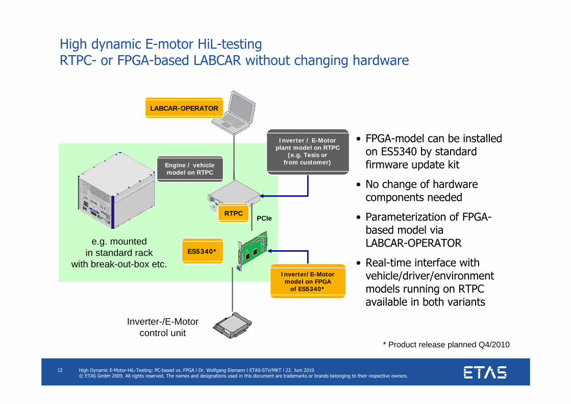
High dynamic E-motor HiL-testing RTPC- or FPGA-based LABCAR without changing hardware
Inverter-/E-Motorcontrol unit
LABCAR-OPERATOR
Inverter / E-Motorplant model on RTPC
(e.g. Tesis orfrom customer)
RTPC
Inverter/E-Motormodel on FPGA
of ES5340*
ES5340*
Engine / vehiclemodel on RTPC
e.g. mountedin standard rack
with break-out-box etc.
PCIe
• FPGA-model can be installed on ES5340 by standard firmware update kit
• No change of hardware components needed
• Parameterization of FPGA-based model viaLABCAR-OPERATOR
• Real-time interface with vehicle/driver/environment models running on RTPC available in both variants
* Product release planned Q4/2010
High Dynamic E-Motor-HiL-Testing: PC-based vs. FPGA l Dr. Wolfgang Eismann l ETAS-STV/MKT l 22. Juni 2010© ETAS GmbH 2009. All rights reserved. The names and designations used in this document are trademarks or brands belonging to their respective owners.
13
High dynamic E-motor HiL-testing Summary
• New PCIe-board ES5340 provides ready-to-use multi-I/O functionalityfor signal-level HiL-testing of Inverter-/E-Motor control
• Product release E 2010• Intermediate solutions already available (ask for migration-option towards ES5340)
• FPGA of ES5340 enables on-board model execution
• Hence, both variants available for Inverter-/E-motor model:• RTPC-based model execution (pin-to-pin latency ≈ 20 µs)
Highly flexibleCost-optimized
• FPGA-based model execution (pin-to-pin latency ≈ 1 µs)Quasi-continuous plant simulation no risk of raster delaySimulation of ripples introduced by inverter switching
• RTPC- or FPGA-based model execution possiblewithout adding or changing any hardware component
High Dynamic E-Motor-HiL-Testing: PC-based vs. FPGA l Dr. Wolfgang Eismann l ETAS-STV/MKT l 22. Juni 2010© ETAS GmbH 2009. All rights reserved. The names and designations used in this document are trademarks or brands belonging to their respective owners.
14
Vielen Dank
Thank you
Merci 有難うございました
감사합니다.
谢谢
धन्यवाद
Muchas gracias


![BIBLIOGRAPHIE - UQACbibvir.uqac.ca/theses/030004861/030004861_bib.pdf · BIBLIOGRAPHIE [1] Baraços P., G. Murere, CA. Rabbath and W. Jin, Enabling PC-based HIL simulation for automotive](https://img.pdfslide.us/doc/110x75/5b98fc3709d3f2fd558ced88/bibliographie-bibliographie-1-baracos-p-g-murere-ca-rabbath-and-w.jpg)