Embed Size (px)
Citation preview

siemens.com/medium-voltage-switchgear
High-current- and generator circuit breaker switchgear
Answers for infrastructure.

High-current- and generator circuit breaker switchgear from Siemens – your benefits
Experience and customer orientationAs a pioneer in development of vacuum switchgear technology for reliable transmission and distribution of electrical power in medium voltage, Siemens has the competence and solutions for the unique switching duties of generator circuits.
In order to serve the high demands of the merging market for power generation sets in the range of 30 MVA at 10.5 kV up to 200 MVA at 18 kV, Siemens has optimized its portfolio of high current and generator circuit breaker switchgear.
The result is a range of switchgear types which are versa-tile in terms of functionality, installation and connection.
3AH38 / 37 vacuum generator circuit breaker n Type tested according IEEE standard C37.013 n High DC-components > 65 % n Maintenance free for 10,000 operating cycles n MTTF (mean time to failure) of 40,000 years
Proof of suitability for the switching application n Computer aided calculation and simulation of short time withstand and peak current under consideration of IEC 60909
n Dimensioning of enclosure and current path to with-stand dynamic and thermal impact of continuous and short circuit currents
n Verification of breaker interruption capabilities under consideration of delayed current zero
Personnel safety and reliability n Design and construction according IEC 62271-1 and IEC 61936-1, type tests according IEC 62271-200
n Internal arc classification (IAC) is available for enclosures of switchgear types HB1 and VB1
n All switching devices to be visually inspected and operated with all doors and covers in closed position.
n No explosion in the unlikely event of a fault in the vacuum interrupter of generator circuit breaker type 3AH38 / 37
HB1 – Horizontal Busbar Generator Switchgear
VB1 – Vertical Busbar Generator Switchgear
HB3 – Phased Segregated Generator Switchgear
HIGS – Highly Integrated Generator Switchgear

HB1 HB1-O VB1
Ur (kV) up to 24 up to 24 up to 24
Ir (A) up to 6700 up to 4800 up to 5500
Ik (kA) / Ip (kAp) up to 72 / 200 up to 72 / 200 up to 72 / 180
IACup to A FLR 72 kA / 0.1 s
–up to A FLR 72 kA / 0.1 s
Installation Indoor Outdoor Indoor
Excitation transformer / SFC feeder
n
Excitation transformer / SFC connection
n n n
Auxiliary transformer feeder
n
Auxiliary transformer connection
n n n
Multiple generator incoming feeder
n
Multiple outgoing feeder n
Cable connection n n n
Busbar connection lateral side
n n
Busbar connection top / bottom
n n n
Switchgear selection guide
Current Transformers
Voltage Transformers
Earthing Switch
Line Disconnector
Vacuum Generator Circuit Breaker
Surge Arresters
Surge Capacitors
Short-Circuit Bridge
-T1;-T3:
-T5; -T6:
-Q5; -Q81:
-Q1:
-Q01:
-F1:
-C1:
-W1:
Control panel
Vacuum generator circuit breaker Proof of suitability Personnel safety and reliability
Flexible connection modes
Seismic tests on 11kV switchgear
Rating: 17.5 kV – 4000A – 72kA/1s
Test report TA34-PB-139/11-01
H:\HyMAS\BERICHT\2011_SIEMENS_11kV\4377_11kV.docx
page 1 of 27
Seismic Qualification Test Report
TA34-PB-139/11-01Seismic tests on11kV Switchgear
Rating: 17.5 kV – 4000A – 72kA/1s
Customer:
SIEMENS AG E D MV 31
IABG Order no.:
340 4377 01
The results in this test report are valid only for the tested specimen.
IABG Festigkeitslabor TA34
Test Laboratory accredited by DAkkS in accordance with
DIN EN ISO/IEC 17025.
The Accreditation is valid only for the standards mentioned
in the Accreditation certificate.
Independent test laboratory, accredited by Deutsche Akkreditierungsstelle Technik (DATech) e.V. in the fields of h.v. apparatus and switchgear, power cables and power cable accessories, l.v. apparatus and switchgear, installation equipment and switching and control equipment. Institut „Prüffeld für elektrische Hochleistungstechnik“ GmbH (IPH Berlin) is a subsidiary of CESI S.p.A, Milan.
Independent, accredited testing station Member laboratory of STL and LOVAG
TYPE TEST REPORT
NO. 2036.2100782.0510
Siemens AG, Energy Sector Power Distribution Division Medium Voltage Mozartstraße 31c 91052 Erlangen GERMANY
CLIENT
Siemens AG, Energy Sector Power Distribution Division Medium Voltage GERMANY
MANUFACTURER
Metal-enclosed AC switchgear (Generator AC switchgear)
TEST OBJECT
HB1 TYPE
Test sample SERIAL NO.
Rated voltage Rated frequency Rated normal current (for IP2X) Rated peak withstand current (main circuits and 3-phase earthing) Rated peak withstand current (1-phase earthing circuits) Rated short-time withstand current main circuits 3-phase earthing circuits 1-phase earthing circuits
Ur
fr
Ip
Ip
Ik
Ik
Ik
Ik
17.5 50/60
6300 198
164
72 63 72 63
kV Hz A kA kA kA, 1 s kA, 3 s kA, 1 s kA, 1 s
RATED CHARACTERISTICS GIVEN BY THE CLIENT
IEC 62271-200: 2003-11 NORMATIVE DOCUMENT
Short-time withstand current and peak withstand current tests RANGE OF TESTS PERFORMED
1 June and 24 August 2010 DATE OF TEST
The ratings of the test object related to the scope of test have been proved. The tests have been PASSED.
TEST RESULT
H. GLABSCH Senior engineer
M. THOM Test engineer in charge
Berlin, 1 June 2011
–Q1
–Q01
–T5–C5
–Q5 –Q81
–T3
3–T1
–W1
–C1
–T6
M M
M
M
–F1
–C81
3
G
–W1 Temporary short circuit bridge
Not scope of supply

HB1 – Horizontal busbar generator circuit breaker switchgear
VB1 – Vertical busbar generator circuit breaker switchgear
General features: n Indoor application IP40 and IP54 n Outdoor application IP54 n Connection by means of cables n Connection from bottom, top or lateral side (metal enclosed bus ducts or fully insulated busbar)
n Connection from lateral side for isolated phased bus duct – IPB ≤ 500 mm phase distance
n Optional connection for SFC starter or excitation transformer (generator side)
n Optional connection for aux.-transformer (transformer side)
General features: n Indoor application IP40 and IP54 n Connection by means of cables n Connection from bottom or top by means of metal enclosed bus ducts or fully insulated busbars
n Optional outgoing feeder with circuit breaker or fuse load break switch for various applications such as: SFC starter, excitation, auxiliary transformer, brake switch
n Multiple generator switchgear, suitable e.g. for 2 generators, 4 transformers, 1 Bus sectionalizer
n Suitable for installation inside containers
Ur 50 Hz * ≤ 17.5 kV 24 kV
Ud (PFWV) ≤ 50 kV 60 kV
Up (BIL) ≤ 110 kV 125 kV
Ir at IP40 / IP54
2900 / 2300 A 4200 / 3300 A 5200 / 3700 A 6700 / 4700 A
Ik / Ip
50 kA / 125 kAp 63 kA / 160 kAp
72 kA / 180 kAp **
IAC availableA FLR 63 kA / 0.1 s A FLR 63 kA / 1 s
A FLR 72 kA / 0.1 s
Ur 50 Hz * ≤ 17.5 kV 24 kV
Ud (PFWV) ≤ 42 kV 60 kV
Up (BIL) ≤ 95 kV 125 kV
Ir at IP40 / IP542500 / 2300 A
up to 5500 / 4500 A
Ik / Ip
50 kA / 125 kAp 63 kA / 160 kAp 72 kA / 180 kAp
IAC availableA FLR 50 kA / 0.5 s A FLR 72 kA / 0.1 s
* 60 Hz on request ** 200 kA on request
X will be defined depending on the type of connection with the switchgear
X = Panel with from 600 mm to 1100 mm. X will be defined depending on the panel functionality
4000 mm + X
23
20
mm
22
00
mm
22
00
mm
6150 mm
X
16
00
mm
+ Y
400 mm
800 mm
425 mm
1800 mm

HB3 – Phase-segregated generator circuit breaker switchgear
HIGS – Highly integrated generator circuit breaker switchgear
Customized Container Solution
General features: n Air-insulated, metal-enclosed, phase segregated generator breaker switchgear
n Fixed mounted circuit breaker with line disconnector for connection to phase insulated busduct systems (IPB)
n Optionally available with auxiliary transformer or excitation feeder
General features: n Air-insulated, metal-enclosed, non-phase segregated generator breaker switchgear
n Directly installed at the generator terminal n Integrated neutral side treatment n Optionally available with integrated auxiliary transformer feeder
Advantage:HIGS as integral part of the generator-set provides cost saving due to reduction of:
n Space requirements n Connection points n Installation
General features: n Customizing of VB1-switchgear to be installed inside containers for severe ambient conditions
n Complete solution including container can be provided
Ur 50 Hz * 17.5 kV 24 kV
Ud (PFWV) 50 kV 60 kV
Up (BIL) 110 kV 125 kV
Ir at IP54 6500 A / 10000 A
Ik / Ip 80 kA / 220 kAp
HIGS 2400 HIGS 3200
Ur 50Hz * 15 kV 12 kV
Ud (PFWV) 38 kV 28 kV
Up (BIL) 95 kV 75 kV
Ir at IP54 / IP42 2400 A 3200 A / 3700 A
Aux.-feeder up to 800 A
Ik / Ip 50 kA /125 kAp
VB1-container for desert ambient conditions of 58 °C in Abu Dhabi
3 x 62 MVA GT power plant in Sweden
1170 mm
2650 mm
19
00
mm
600
34301200
2500
Siemens AG Infrastructure & Cities Sector Low and Medium Voltage Division P.O. Box 3240 91050 Erlangen, Germany
www.siemens.com/medium-voltage-switchgear
For more information, please contact our Customer Support Center. Phone: +49 180 524 8437* Fax: +49 180 5CITIES* (Charges depending on provider) E-mail: [email protected] © Siemens AG 2011 Printed in Germany TH 260-111225 WS 1211
All rights reserved. Trademarks mentioned in this document are the property of Siemens AG, its affiliates, or their respective owners.
Subject to change without prior notice. The information in this document contains general descriptions of the technical options available, which do not always have to be present in individual cases. The required features should therefore be specified in each individual case at the time of closing the contract.
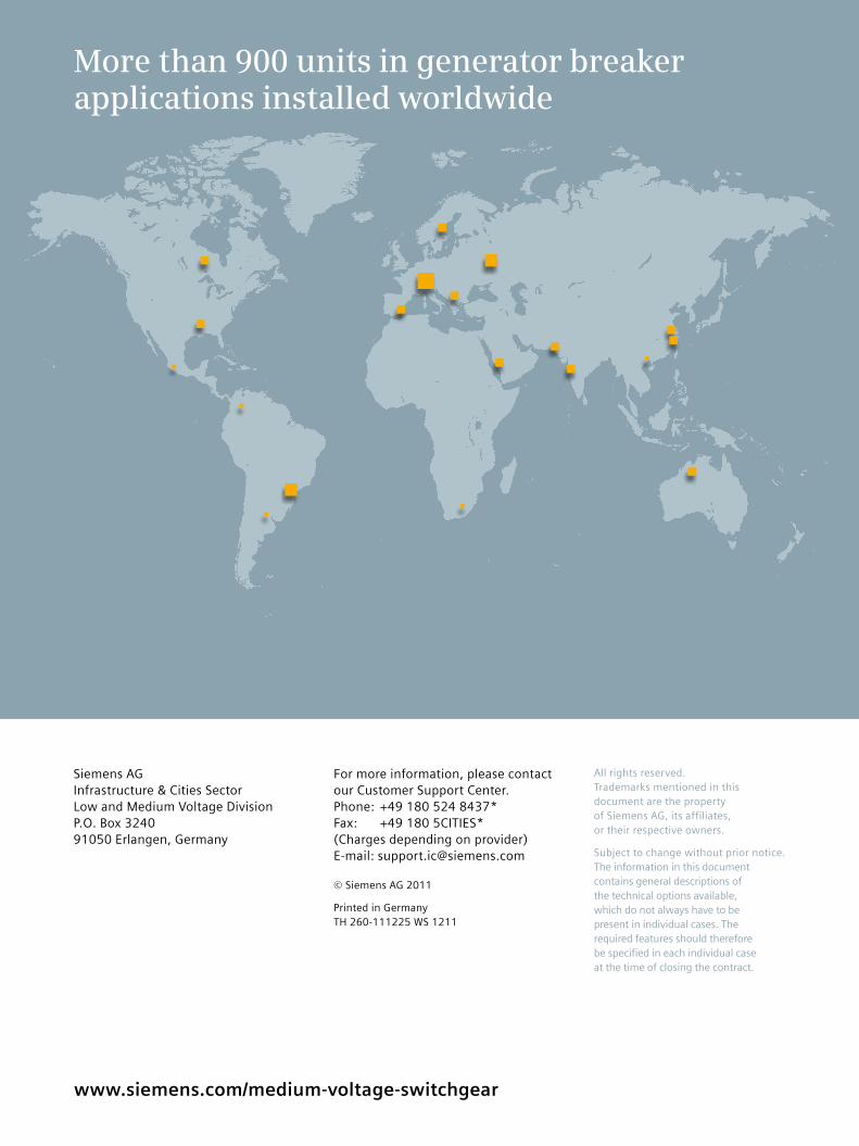
More than 900 units in generator breaker applications installed worldwide