Embed Size (px)
Citation preview

High Availability Configuration Guide
Americas HeadquartersCisco Systems, Inc.170 West Tasman DriveSan Jose, CA 95134-1706USAhttp://www.cisco.comTel: 408 526-4000 800 553-NETS (6387)Fax: 408 527-0883

THE SPECIFICATIONS AND INFORMATION REGARDING THE PRODUCTS IN THIS MANUAL ARE SUBJECT TO CHANGE WITHOUT NOTICE. ALL STATEMENTS,INFORMATION, AND RECOMMENDATIONS IN THIS MANUAL ARE BELIEVED TO BE ACCURATE BUT ARE PRESENTED WITHOUT WARRANTY OF ANY KIND,EXPRESS OR IMPLIED. USERS MUST TAKE FULL RESPONSIBILITY FOR THEIR APPLICATION OF ANY PRODUCTS.
THE SOFTWARE LICENSE AND LIMITEDWARRANTY FOR THE ACCOMPANYING PRODUCT ARE SET FORTH IN THE INFORMATION PACKET THAT SHIPPED WITHTHE PRODUCT AND ARE INCORPORATED HEREIN BY THIS REFERENCE. IF YOU ARE UNABLE TO LOCATE THE SOFTWARE LICENSE OR LIMITED WARRANTY,CONTACT YOUR CISCO REPRESENTATIVE FOR A COPY.
The Cisco implementation of TCP header compression is an adaptation of a program developed by the University of California, Berkeley (UCB) as part of UCB's public domain versionof the UNIX operating system. All rights reserved. Copyright © 1981, Regents of the University of California.
NOTWITHSTANDINGANYOTHERWARRANTYHEREIN, ALL DOCUMENT FILES AND SOFTWARE OF THESE SUPPLIERS ARE PROVIDED “AS IS"WITH ALL FAULTS.CISCO AND THE ABOVE-NAMED SUPPLIERS DISCLAIM ALL WARRANTIES, EXPRESSED OR IMPLIED, INCLUDING, WITHOUT LIMITATION, THOSE OFMERCHANTABILITY, FITNESS FORA PARTICULAR PURPOSEANDNONINFRINGEMENTORARISING FROMACOURSEOFDEALING, USAGE, OR TRADE PRACTICE.
IN NO EVENT SHALL CISCO OR ITS SUPPLIERS BE LIABLE FOR ANY INDIRECT, SPECIAL, CONSEQUENTIAL, OR INCIDENTAL DAMAGES, INCLUDING, WITHOUTLIMITATION, LOST PROFITS OR LOSS OR DAMAGE TO DATA ARISING OUT OF THE USE OR INABILITY TO USE THIS MANUAL, EVEN IF CISCO OR ITS SUPPLIERSHAVE BEEN ADVISED OF THE POSSIBILITY OF SUCH DAMAGES.
Any Internet Protocol (IP) addresses and phone numbers used in this document are not intended to be actual addresses and phone numbers. Any examples, command display output, networktopology diagrams, and other figures included in the document are shown for illustrative purposes only. Any use of actual IP addresses or phone numbers in illustrative content is unintentionaland coincidental.
Cisco and the Cisco logo are trademarks or registered trademarks of Cisco and/or its affiliates in the U.S. and other countries. To view a list of Cisco trademarks, go to this URL: http://www.cisco.com/go/trademarks. Third-party trademarks mentioned are the property of their respective owners. The use of the word partner does not imply a partnershiprelationship between Cisco and any other company. (1110R)
© 2017 Cisco Systems, Inc. All rights reserved.
C O N T E N T S
C H A P T E R 1 Read Me First 1
C H A P T E R 2 Configuring Stateful Switchover 3
Finding Feature Information 3
Prerequisites for Stateful Switchover 4
General Prerequisites 4
Cisco 10000 Series Devices Prerequisites 4
Cisco 7500 Series Internet Router Platform Prerequisites 4
Restrictions for Stateful Switchover 4
General Restrictions for SSO 4
Configuration Mode Restrictions 5
Switchover Process Restrictions 5
ATM Restrictions 5
Frame Relay and Multilink Frame Relay Restrictions 6
PPP Restrictions 7
Cisco ASR 1000 Series Aggregation Services Routers Restrictions 7
Information About Stateful Switchover 7
SSO Overview 7
Redundancy Modes 9
High System Availability 9
Route Processor Redundancy Mode 9
Route Processor Redundancy Plus 10
Stateful Switchover Mode 10
Redundancy Modes by Platform and Software Release 10
Route Processor Synchronization 12
Bulk Synchronization During Initialization 12
Incremental Synchronization 13
Switchover Operation 14
High Availability Configuration Guide iii
Switchover Conditions 14
Switchover Time 14
Online Removal of the Active RP 15
Fast Software Upgrade 15
Core Dump Operation 15
Virtual Template Manager for SSO 16
SSO-Aware Protocols and Applications 16
Line Protocols 16
Supported Line protocols by Platform 17
ATM Stateful Switchover 19
Frame Relay and Multilink Frame Relay Stateful Switchover 20
PPP and Multilink PPP Stateful Switchover 21
HDLC Stateful Switchover 21
Quality of Service 22
IPv6 Support for Stateful Switchover 22
Line Card Drivers 22
APS 22
Routing Protocols and Nonstop Forwarding 22
Network Management 23
SSO for Circuit Emulation Services 23
How to Configure Stateful Switchover 23
Copying an Image onto an RP 23
Setting the Configuration Register and Boot Variable 24
Configuring SSO 26
Configuring Frame Relay and Multilink Frame Relay Autosynchronization LMI Sequence
Numbers 28
Verifying SSO Configuration 29
Performing a Fast Software Upgrade 29
Troubleshooting Stateful Switchover 32
Troubleshooting SSO 33
Configuration Examples for Stateful Switchover 34
Example Verifying that SSO Is Configured on Various Platforms 34
Example Verifying that SSO Is Operating on the Device 37
Example Verifying SSO Protocols and Applications 38
Additional References 40
High Availability Configuration Guideiv
Contents
Feature Information for Stateful Switchover 42
C H A P T E R 3 Configuring Nonstop Forwarding 47
Finding Feature Information 47
Prerequisites for Nonstop Forwarding 48
Restrictions for Nonstop Forwarding 48
General Restrictions 48
BGP NSF Restrictions 48
EIGRP NSF Restrictions 49
OSPF NSF Restrictions 49
Cisco7200SeriesRouterRestrictions 49
Information About Nonstop Forwarding 50
Nonstop Forwarding 50
Cisco NSF Routing and Forwarding 50
Routing Protocols and CEF Support in Cisco NSF 51
Cisco Express Forwarding and NSF 53
BGP NSF Operations 53
EIGRP NSF Operations 54
IPv6 support for NSF Operations 55
Nonstop Forwarding and Graceful Restart for MP-BGP IPv6 Address Family 55
Nonstop Forwarding for IPv6 RIP 55
Nonstop Forwarding for Static Routes 55
IS-IS NSF Operations 55
IETF IS-IS Configuration 56
Cisco IS-IS Configuration 56
NSF-OSPF Operations 57
How to Configure Nonstop Forwarding 57
Configuring and Verifying BGP NSF 57
Configuring and Verifying EIGRP NSF 58
Configuring NSF-OSPF 60
Configuring Cisco NSF-OSPF 61
Configuring IETF NSF-OSPF 62
Configuring and Verifying IS-IS NSF 64
Troubleshooting Nonstop Forwarding 66
Configuration Examples for Nonstop Forwarding 68
High Availability Configuration Guide v
Contents
Example NSF-Capable CEF 68
Example BGP NSF 69
Example: EIGRP NSF 69
Example: Configuring Cisco NSF-OSPF 70
Example: Configuring IETF NSF-OSPF 70
Example IS-ISNSF 71
Additional References 72
Feature Information for Nonstop Forwarding 74
C H A P T E R 4 Performing an In Service Software Upgrade 79
Finding Feature Information 79
Information About Performing an ISSU 79
ISSU Process Overview 79
ISSU and the Cisco ASR 1000 Series Router 81
How to Perform an ISSU 81
Configuration Examples for Performing an ISSU 81
Example Verifying Redundancy Mode Before Beginning the ISSU Process 81
Example Verifying the ISSU State 82
Additional References 82
Feature Information for Performing an XE ISSU 84
C H A P T E R 5 AAA High Availability Support for Local PPPoX Sessions 87
Finding Feature Information 87
Restrictions for AAA High Availability Support for Local PPPoX Sessions 88
Information About AAA High Availability Support for Local PPPoX Sessions 88
AAA HA Enhancement 88
HA and Authentication 89
HA and Authorization 89
HA and Accounting 89
System Accounting 89
Periodic Accounting 90
How to Configure AAA High Availability Support for Local PPPoX Sessions 90
Configuring AAA High Availability Support for Local PPPoX Sessions 90
Troubleshooting an AAA High Availability Configuration 90
Additional References 91
High Availability Configuration Guidevi
Contents

Feature Information for AAA High Availability Support for Local PPPoX Sessions 93
High Availability Configuration Guide vii
Contents

High Availability Configuration Guideviii
Contents

C H A P T E R 1Read Me First
Important Information about Cisco IOS XE 16
Effective Cisco IOS XE Release 3.7.0E (for Catalyst Switching) and Cisco IOS XE Release 3.17S (forAccess and Edge Routing) the two releases evolve (merge) into a single version of converged release—theCisco IOS XE 16—providing one release covering the extensive range of access and edge products in theSwitching and Routing portfolio.
The Feature Information table in the technology configuration guide mentions when a feature wasintroduced. It may or may not mention when other platforms were supported for that feature. To determineif a particular feature is supported on your platform, look at the technology configuration guides postedon your product landing page.When a technology configuration guide is displayed on your product landingpage, it indicates that the feature is supported on that platform.
Note
High Availability Configuration Guide 1

High Availability Configuration Guide2
Read Me First
C H A P T E R 2Configuring Stateful Switchover
The Stateful Switchover (SSO) feature works with Nonstop Forwarding (NSF) in Cisco software to minimizethe amount of time a network is unavailable to its users following a switchover. The primary objective ofSSO is to improve the availability of networks constructed with Cisco routers. SSO performs the followingfunctions:
• Maintains stateful protocol and application information to retain user session information during aswitchover.
• Enables line cards to continue to forward network traffic with no loss of sessions, providing improvednetwork availability.
• Provides a faster switchover relative to high system availability.
• Finding Feature Information, page 3
• Prerequisites for Stateful Switchover, page 4
• Restrictions for Stateful Switchover, page 4
• Information About Stateful Switchover, page 7
• How to Configure Stateful Switchover, page 23
• Configuration Examples for Stateful Switchover, page 34
• Additional References, page 40
• Feature Information for Stateful Switchover, page 42
Finding Feature InformationYour software release may not support all the features documented in this module. For the latest caveats andfeature information, see Bug Search Tool and the release notes for your platform and software release. Tofind information about the features documented in this module, and to see a list of the releases in which eachfeature is supported, see the feature information table.
Use Cisco Feature Navigator to find information about platform support and Cisco software image support.To access Cisco Feature Navigator, go to www.cisco.com/go/cfn. An account on Cisco.com is not required.
High Availability Configuration Guide 3
Prerequisites for Stateful Switchover
General Prerequisites•• Before copying a file to flash memory, be sure that ample space is available in flash memory. Comparethe size of the file you are copying to the amount of available flash memory shown. If the space availableis less than the space required by the file you will copy, the copy process will not continue and an errormessage similar to the following will be displayed:
%Error copying tftp://image@server/tftpboot/filelocation/imagename (Not enough space ondevice).
•• For Nonstop Forwarding (NSF) support, neighbor routers must be running NSF-enabled images, thoughSSO need not be configured on the neighbor device.
Cisco 10000 Series Devices Prerequisites• On Cisco 10000 series devices only, to boot both Performance Routing Engines (PREs) from the TFTPboot server, you must use the ip address negotiated command in interface configuration mode to enableDHCP on the PRE. Otherwise, you will get a duplicate IP address error because of the synchronizationof the IP address from the active to the standby Route Processor (RP).
Cisco 7500 Series Internet Router Platform Prerequisites• On the Cisco 7507 and Cisco 7513 routers, any combination of RSP8 and RSP16 devices, or anycombination of RSP2 and RSP4, are required.
Restrictions for Stateful Switchover
General Restrictions for SSO• Configuration changes made through SNMP may not be automatically configured on the standby RPafter a switchover occurs.
• TheHot Standby Routing Protocol (HSRP) is not supported with Cisco Nonstop Forwarding with StatefulSwitchover. Do not use HSRP with Cisco Nonstop Forwarding with Stateful Switchover.
High Availability Configuration Guide4
Configuring Stateful SwitchoverPrerequisites for Stateful Switchover
• Enhanced Object Tracking (EOT) is not stateful switchover-aware and cannot be used with HSRP,Virtual Router Redundancy Protocol (VRRP), or Gateway Load Balancing Protocol (GLBP) in SSOmode.
• Multicast is not SSO-aware and restarts after switchover; therefore, multicast tables and data structuresare cleared upon switchover.
Configuration Mode Restrictions• The configuration registers on both RPs must be set the same for the networking device to behave thesame when either RP is rebooted.
• During the startup (bulk) synchronization, configuration changes are not allowed. Before making anyconfiguration changes, wait for a message similar to the following:
%HA-5-MODE:Operating mode is sso, configured mode is sso.
%HA-6-STANDBY_READY: Standby RP in slot nis operational in SSO mode
Switchover Process Restrictions• If the router is configured for SSO mode, and the active RP fails before the standby is ready to switchover, the router will recover through a full system reset.
ATM Restrictions• Label-controlled ATM (LC-ATM) functionality does not co-exist with SSO in this release.
• The ATM line protocol does not support stateful switchover capability for the following features in thisrelease:
• SVCs
• Switched virtual paths (SVPs)
• Tagged virtual circuits (TVCs)
• Point-to-multipoint SVC
• Integrated Local Management Interface (ILMI)
• Signaling and Service Specific Connection Oriented Protocol (SSCOP)
• ATM Connection Manager, permanent virtual circuit (PVC) discovery, ATM applications
• Backward or version compatibility
• Statistics and accounting
• Zero ATM cell loss
High Availability Configuration Guide 5
Configuring Stateful SwitchoverConfiguration Mode Restrictions
Frame Relay and Multilink Frame Relay Restrictions• The following Frame Relay features are not synchronized between the active and standby RPs in thisrelease: Frame Relay statistics; enhanced LMI (ELMI); Link Access Procedure, Frame Relay (LAPF);SVCs; and subinterface line state.
The subinterface line state is determined by the PVC state, which follows the line card protocol state onDCE interfaces, and is learned from first LMI status exchange after switchover on DTE interfaces.
Note
• Frame Relay SSO is supported with the following features:
• Serial interfaces
• DTE and DCE LMI (or no keepalives)
• PVCs (terminated and switched)
• IP
•When no LMI type is explicitly configured on a DTE interface, the autosensed LMI type is synchronized.
• LMI sequence numbers are not synchronized between the active and standby RPs by default.
LMI keepalive messages contain sequence numbers so that each side (network and peer) of a PVC can detecterrors. An incorrect sequence number counts as one error. By default, the switch declares the line protocoland all PVCs down after three consecutive errors. Although it seems that synchronizing LMI sequence numbersmight prevent dropped PVCs, the use of resources required to synchronize LMI sequence numbers forpotentially thousands of interfaces (channelized) on larger networking devices might be a problem in itself.The networking device can be configured to synchronize LMI sequence numbers. Synchronization of sequencenumbers is not necessary for DCE interfaces.
• Changes to the line protocol state are synchronized between the active and standby RPs. The line protocolis assumed to be up on switchover, providing that the interface is up.
• PVC state changes are not synchronized between the active and standby RPs. The PVC is set to the upstate on switchover provided that the line protocol state is up. The true state is determined when the firstfull status message is received from the switch on DTE interfaces.
• Subinterface line state is not synchronized between the active and standby RPs. Subinterface line stateis controlled by the PVC state, by configuration settings, or by the hardware interface state when thePVC is up. On switchover, the subinterface state is set to up, providing that the subinterfaces are notshut down and the main interface is up and the line protocol state is up. On DTE devices, the correctstate is learned after the first LMI status exchange.
• Dynamic maps are not synchronized between the active and standby RPs. Adjacency changes as a resultof dynamic map change are relearned after switchover.
• Dynamically learned PVCs are synchronized between the active and standby RPs and are relearned afterthe first LMI status exchange.
• For Multilink Frame Relay bundle links, the state of the local bundle link and peer bundle ID issynchronized.
High Availability Configuration Guide6
Configuring Stateful SwitchoverFrame Relay and Multilink Frame Relay Restrictions
• For a Multilink Frame Relay bundle, the peer ID is synchronized.
PPP Restrictions• The following PPP features are not supported: dialer; authentication, authorization, and accounting(AAA), IPPOOL, Layer 2 (L2X), Point-to-Point Tunneling Protocol (PPTP), Microsoft Point-to-pointEncryption (MPPE), LinkQualityMonitoring (LQM), link or header compression, bridging, asynchronousPPP, and XXCP.
Cisco ASR 1000 Series Aggregation Services Routers Restrictions• Only RPR and SSO are supported on Cisco ASR 1000 Aggregation Services routers.
• RPR and SSO can be used on Cisco ASR 1000 Aggregation Services routers to enable a second Ciscosoftware process on a single RP. This configuration option is only available on Cisco ASR 1002 andCisco ASR 1004 routers. On all other Cisco ASR 1000 Aggregation Services routers, the second Ciscosoftware process can run on the standby RP only.
• A second Cisco software process can only be enabled using RPR or SSO if the RP is using 8 GB ofDRAM. The show version command output shows the amount of DRAM configured on the router.
• Enabling software redundancy on the Cisco ASR 1001, 1002, and 1004 routers can reduce the CiscoIOS memory by more than half and adversely affect control plane scalability. We recommend that youuse hardware redundant platforms, such as the Cisco ASR 1006 or 1013 routers, in networks where bothscalability and high availability are critical.
• CiscoASR 1000 Series Router software redundancy requires an RTU license (FLASR1-IOSRED-RTU(=)on ASR 1002; and FLSASR1-IOSRED(=) on ASR 1001, ASR 1001-X, ASR 1001-HX, ASR 1002-HX,and ASR 1002-X), which allows you to enable software redundancy on the Cisco ASR 1001, ASR 1002,ASR 1001-X, ASR 1001-HX, ASR 1002-HX, ASR 1002-X, andASR 1004 chassis. Software redundancyrequires 4-GB DRAM on the RP1, and minimum 8-GB DRAM on the ASR 1001, ASR 1001-X, ASR1001-HX, or ASR 1002-X. The Cisco ASR 1001, ASR 1002, and ASR 1002-X come by default with4-GB DRAM on the built-in route processor, the ASR 1001-X and ASR 1001-HX come by default with8-GB DRAM, and the ASR 1002-HX comes by default with 16-GB DRAM.
Information About Stateful Switchover
SSO OverviewSSO provides protection for network edge devices with dual RPs that represent a single point of failure in thenetwork design, and where an outage might result in loss of service for customers.
In Cisco networking devices that support dual RPs, SSO takes advantage of RP redundancy to increase networkavailability. The feature establishes one of the RPs as the active processor while the other RP is designatedas the standby processor, and then synchronizing critical state information between them. Following an initialsynchronization between the two processors, SSO dynamically maintains RP state information between them.
High Availability Configuration Guide 7
Configuring Stateful SwitchoverPPP Restrictions
A switchover from the active to the standby processor occurs when the active RP fails, is removed from thenetworking device, or is manually taken down for maintenance.
SSO is used with the Cisco Nonstop Forwarding (NSF) feature. Cisco NSF allows for the forwarding of datapackets to continue along known routes while the routing protocol information is being restored following aswitchover. With Cisco NSF, peer networking devices do not experience routing flaps, thereby reducing lossof service outages for customers.
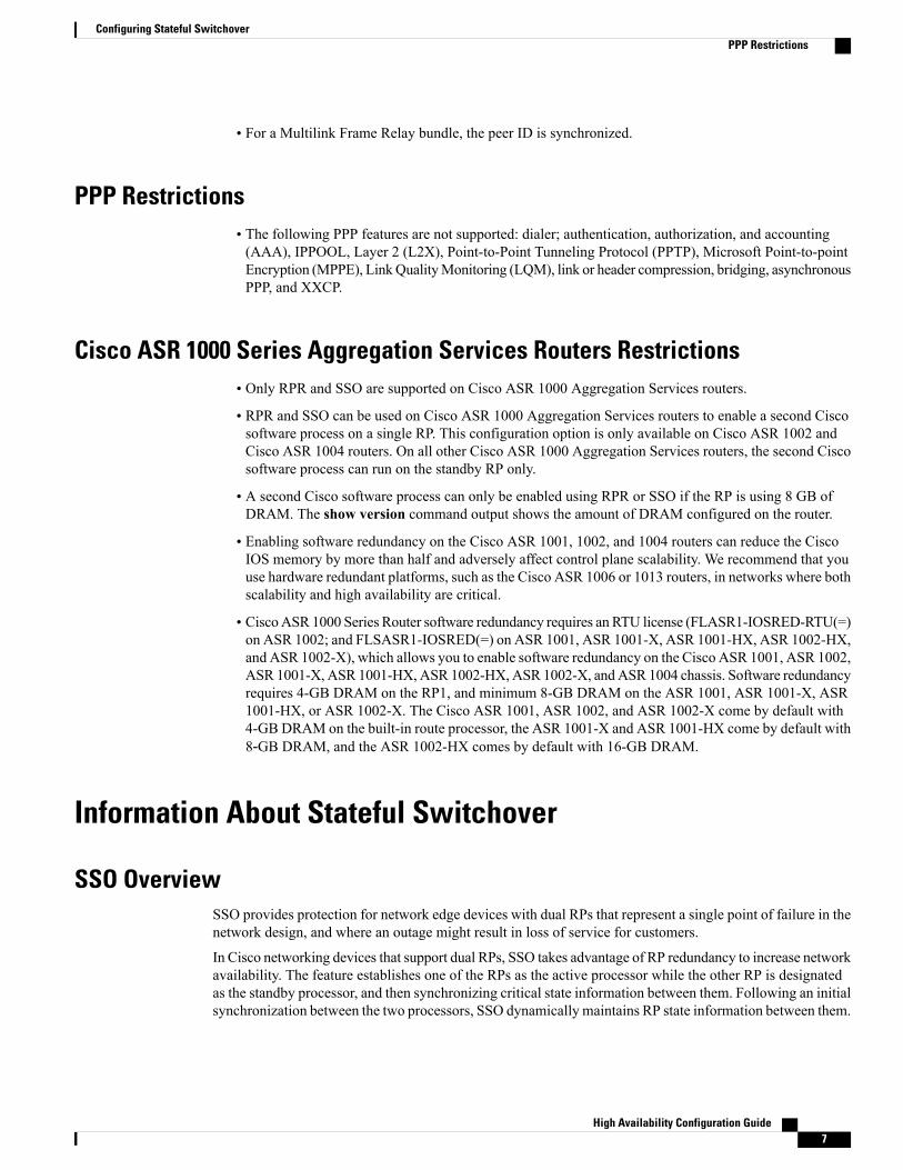
The figure below illustrates how SSO is typically deployed in service provider networks. In this example,Cisco NSF with SSO is primarily at the access layer (edge) of the service provider network. A fault at thispoint could result in loss of service for enterprise customers requiring access to the service provider network.
Figure 1: Cisco NSF with SSO Network Deployment: Service Provider Networks
For Cisco NSF protocols that require neighboring devices to participate in Cisco NSF, Cisco NSF-awaresoftware images must be installed on those neighboring distribution layer devices. Additional networkavailability benefits might be achieved by applying Cisco NSF and SSO features at the core layer of yournetwork; however, consult your network design engineers to evaluate your specific site requirements.
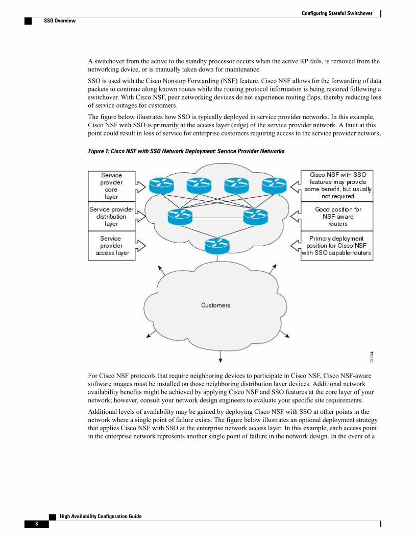
Additional levels of availability may be gained by deploying Cisco NSF with SSO at other points in thenetwork where a single point of failure exists. The figure below illustrates an optional deployment strategythat applies Cisco NSF with SSO at the enterprise network access layer. In this example, each access pointin the enterprise network represents another single point of failure in the network design. In the event of a
High Availability Configuration Guide8
Configuring Stateful SwitchoverSSO Overview
switchover or a planned software upgrade, enterprise customer sessions would continue uninterrupted throughthe network.
Figure 2: Cisco NSF with SSO Network Deployment: Enterprise Networks
Redundancy Modes
High System AvailabilityHSA mode allows you to install two RPs in a single router to improve system availability. This mode isavailable only on Cisco 7500 series routers. Supporting two RPs in a router provides the most basic level ofincreased system availability through a “cold restart” feature. A cold restart means that when one RP fails, theother RP reboots the router. Thus, the router is never in a failed state for very long, thereby increasing systemavailability.
Route Processor Redundancy ModeRouter Processor Redundancy (RPR) allows Cisco software to be booted on the standby processor prior toswitchover (a cold boot). In RPR, the standby RP loads a Cisco software image at boot time and initializesitself in standby mode; however, although the startup configuration is synchronized to the standby RP, systemchanges are not. In the event of a fatal error on the active RP, the system switches to the standby processor,which reinitializes itself as the active processor, reads and parses the startup configuration, reloads all of theline cards, and restarts the system.
High Availability Configuration Guide 9
Configuring Stateful SwitchoverRedundancy Modes
Route Processor Redundancy PlusIn RPR+ mode, the standby RP is fully initialized. For RPR+ both the active RP and the standby RP must berunning the same software image. The active RP dynamically synchronizes startup and the running configurationchanges to the standby RP, meaning that the standby RP need not be reloaded and reinitialized (a hot boot).
Additionally, on the Cisco 10000 and 12000 series Internet routers, the line cards are not reset in RPR+mode.This functionality provides a much faster switchover between the processors. Information synchronized tothe standby RP includes running configuration information, startup information (Cisco 7304, Cisco 7500,Cisco 10000, and Cisco 12000 series networking devices), and changes to the chassis state such as onlineinsertion and removal (OIR) of hardware. Line card, protocol, and application state information is notsynchronized to the standby RP.
Stateful Switchover Mode
Redundancy Modes by Platform and Software Release
During normal operation, SSO is the only supported mode for the Cisco 10000 series Internet routers.Note
The five tables below show redundancy modes by platform and release.
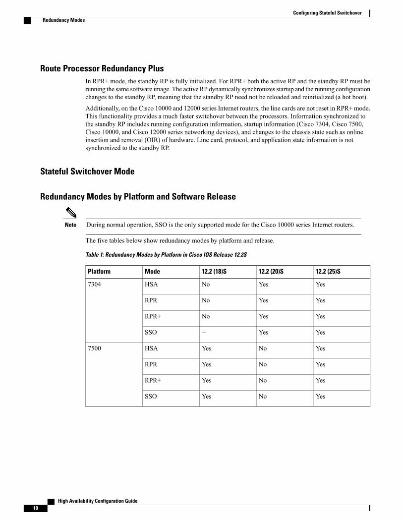
Table 1: Redundancy Modes by Platform in Cisco IOS Release 12.2S
12.2 (25)S12.2 (20)S12.2 (18)SModePlatform
YesYesNoHSA7304
YesYesNoRPR
YesYesNoRPR+
YesYes--SSO
YesNoYesHSA7500
YesNoYesRPR
YesNoYesRPR+
YesNoYesSSO
High Availability Configuration Guide10
Configuring Stateful SwitchoverRedundancy Modes
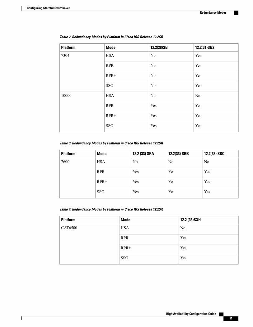
Table 2: Redundancy Modes by Platform in Cisco IOS Release 12.2SB
12.2(31)SB212.2(28)SBModePlatform
YesNoHSA7304
YesNoRPR
YesNoRPR+
YesNoSSO
NoNoHSA10000
YesYesRPR
YesYesRPR+
YesYesSSO
Table 3: Redundancy Modes by Platform in Cisco IOS Release 12.2SR
12.2(33) SRC12.2(33) SRB12.2 (33) SRAModePlatform
NoNoNoHSA7600
YesYesYesRPR
YesYesYesRPR+
YesYesYesSSO
Table 4: Redundancy Modes by Platform in Cisco IOS Release 12.2SX
12.2 (33)SXHModePlatform
NoHSACAT6500
YesRPR
YesRPR+
YesSSO
High Availability Configuration Guide 11
Configuring Stateful SwitchoverRedundancy Modes
Table 5: Redundancy Modes by Platform in Cisco IOS Release 12.0S
Redundancy Mode Support in Cisco IOS Releases
12.0(28)S12.0(26)S12.0(24)S12.0(23)S12.0(22)SModePlatform
YesYesYesYesYesHSA7500
YesYesYesYesYesRPR
YesYesYesYesYesRPR+
YesYesYesYesYesSSO
NoNoNoNoNoHSA10000
NoNoNoNoNoRPR
YesYesYesYesYesRPR+
YesYesYesYesYesSSO
NoNoNoNoNoHSA12000
YesYesYesYesYesRPR
YesYesYesYesYesRPR+
YesYesYesYesYesSSO
Route Processor SynchronizationIn networking devices running SSO, both RPs must be running the same configuration so that the standby RPis always ready to assume control if the active RP fails.
To achieve the benefits of SSO, synchronize the configuration information from the active RP to the standbyRP at startup and whenever changes to the active RP configuration occur. This synchronization occurs in twoseparate phases:
•While the standby RP is booting, the configuration information is synchronized in bulk from the activeRP to the standby RP.
•When configuration or state changes occur, an incremental synchronization is conducted from the activeRP to the standby RP.
Bulk Synchronization During InitializationWhen a system with SSO is initialized, the active RP performs a chassis discovery (discovery of the numberand type of line cards and fabric cards, if available, in the system) and parses the startup configuration file.
High Availability Configuration Guide12
Configuring Stateful SwitchoverRoute Processor Synchronization
The active RP then synchronizes this data to the standby RP and instructs the standby RP to complete itsinitialization. This method ensures that both RPs contain the same configuration information.
Even though the standby RP is fully initialized, it interacts only with the active RP to receive incrementalchanges to the configuration files as they occur. Executing CLI commands on the standby RP is not supported.
During system startup, the startup configuration file is copied from the active RP to the standby RP. Anyexisting startup configuration file on the standby RP is overwritten. The startup configuration is a text filestored in the NVRAM of the RP. It is synchronized whenever you perform the following operations:
• The command copy system:running-config nvram:startup-config is used.
• The command copy running-config startup-config is used.
• The command write memory is used.
• The command copy filename nvram:startup-config is used.
• SNMP SET of MIB variable ccCopyEntry in CISCO_CONFIG_COPY MIB is used.
• System configuration is saved using the reload command.
• System configuration is saved following entry of a forced switchover command.
Incremental SynchronizationAfter both RPs are fully initialized, any further changes to the running configuration or active RP states aresynchronized to the standby RP as they occur. Active RP states are updated as a result of processing protocolinformation, external events (such as the interface becoming up or down), or user configuration commands(using Cisco IOS commands or Simple Network Management Protocol [SNMP]) or other internal events.
Changes to the running configuration are synchronized from the active RP to the standby RP. In effect, thecommand is run on both the active and the standby RP.
Configuration changes caused by an SNMP set operation are synchronized on a case-by-case basis. Only twoSNMP configuration set operations are supported:
• shut and no-shut (of an interface)
• link up/down trap enable/disable
Routing and forwarding information is synchronized to the standby RP:
• State changes for SSO-aware protocols (ATM, Frame Relay, PPP, High-Level Data Link Control[HDLC]) or applications (SNMP) are synchronized to the standby RP.
• Cisco Express Forwarding (CEF) updates to the Forwarding Information Base (FIB) are synchronizedto the standby RP.
Chassis state changes are synchronized to the standby RP. Changes to the chassis state due to line card insertionor removal are synchronized to the standby RP.
Changes to the line card states are synchronized to the standby RP. Line card state information is initiallyobtained during bulk synchronization of the standby RP. Following bulk synchronization, line card events,such as whether the interface is up or down, received at the active processor are synchronized to the standbyRP.
High Availability Configuration Guide 13
Configuring Stateful SwitchoverRoute Processor Synchronization
The various counters and statistics maintained in the active RP are not synchronized because they may changeoften and because the degree of synchronization they require is substantial. The volume of informationassociated with statistics makes synchronizing them impractical.
Not synchronizing counters and statistics between RPs may create problems for external network managementsystems that monitor this information.
Switchover Operation
Switchover ConditionsAn automatic or manual switchover may occur under the following conditions:
• A fault condition that causes the active RP to crash or reboot--automatic switchover
• The active RP is declared dead (not responding)--automatic switchover
• The command is invoked--manual switchover
The user can force the switchover from the active RP to the standby RP by using a CLI command. This manualprocedure allows for a graceful or controlled shutdown of the active RP and switchover to the standby RP.This graceful shutdown allows critical cleanup to occur.
This procedure should not be confused with the graceful shutdown procedure for routing protocols in corerouters--they are separate mechanisms.
Note
The SSO feature introduces a number of new command and command changes, including commands tomanually cause a switchover. The reload command does not cause a switchover. The reload commandcauses a full reload of the box, removing all table entries, resetting all line cards, and interrupting nonstopforwarding.
Caution
Switchover TimeThe time required by the device to switch over from the active RP to the standby RP varies by platform:
• On the Cisco 7500 series devices, switchover time is approximately 30 seconds.
• On the Cisco 7304 and Cisco 10000 series devices, switchover time is only a few seconds.
• On the Cisco 12000 series devices, switchover time due to a manual switchover or due to automaticswitchover caused by an error is only a few seconds. If the switchover is caused by a fault on the activeRP, the standby RP will detect the problem following the switchover timeout period, which is set tothree seconds by default.
• On the Cisco ASR 1000 series routers, switchover time is only a few seconds.
Although the newly active processor takes over almost immediately following a switchover, the time requiredfor the device to begin operating again in full redundancy (SSO) mode can be several minutes, depending on
High Availability Configuration Guide14
Configuring Stateful SwitchoverSwitchover Operation
the platform. The length of time can be due to a number of factors including the time needed for the previouslyactive processor to obtain crash information, load code andmicrocode, and synchronize configurations betweenprocessors and line protocols and Cisco NSF-supported protocols.
The impact of the switchover time on packet forwarding depends on the networking device:
• On the Cisco 7500 series devices, forwarding information is distributed, and packets forwarded fromthe same line card should have little to no forwarding delay; however, forwarding packets between linecards requires interaction with the RP, meaning that packet forwarding might have to wait for theswitchover time. The switchover time on Cisco 7500 series devices is also dependent on the type ofRSPs installed on the system.
• On the Cisco 10000 series devices, Cisco Express Forwarding information resides on the RP, so packetforwarding can be impacted momentarily while the switchover occurs.
• On the Cisco 12000 series devices, complete forwarding information is distributed to the line cards, sopacket forwarding is not impacted as long as the line cards are working.
Online Removal of the Active RPFor Cisco 7500 series routers, online removal of the active RSP will automatically switch the redundancymode to RPR. Online removal of the active RSP causes all line cards to reset and reload, which is equivalentto an RPR switchover, and results in a longer switchover time. When it is necessary to remove the active RPfrom the system, first issue a switchover command to switch from the active RSP to the standby RSP. Whena switchover is forced to the standby RSP before the previously active RSP is removed, the network operationbenefits from the continuous forwarding capability of SSO.
For Cisco 7304, Cisco 10000, and Cisco 12000 series Internet routers that are configured to use SSO, onlineremoval of the active RP automatically forces a stateful switchover to the standby RP.
Fast Software UpgradeYou can use Fast Software Upgrade (FSU) to reduce planned downtime. With FSU, you can configure thesystem to switch over to a standby RP that is preloaded with an upgraded Cisco software image. FSU reducesoutage time during a software upgrade by transferring functions to the standby RP that has the upgraded Ciscosoftware preinstalled. You can also use FSU to downgrade a system to an older version of Cisco software orhave a backup system loaded for downgrading to a previous image immediately after an upgrade.
SSO must be configured on the networking device before performing FSU.
During the upgrade process, different images will be loaded on the RPs for a short period of time. Duringthis time, the device will operate in RPR or RPR+ mode, depending on the networking device.
Note
Core Dump OperationIn networking devices that support SSO, the newly active primary processor runs the core dump operationafter the switchover has taken place. Not having to wait for dump operations effectively decreases the switchovertime between processors.
High Availability Configuration Guide 15
Configuring Stateful SwitchoverSwitchover Operation
Following the switchover, the newly active RP will wait for a period of time for the core dump to completebefore attempting to reload the formerly active RP. The time period is configurable. For example, on someplatforms an hour or more may be required for the formerly active RP to perform a coredump, and it mightnot be site policy to wait that much time before resetting and reloading the formerly active RP. In the eventthat the core dump does not complete within the time period provided, the standby is reset and reloadedregardless of whether it is still performing a core dump.
The core dump process adds the slot number to the core dump file to identify which processor generated thefile content.
Core dumps are generally useful only to your technical support representative. The core dump file, whichis a very large binary file, must be transferred using the TFTP, FTP, or remote copy protocol (rcp) serverand subsequently interpreted by a Cisco Technical Assistance Center (TAC) representative that has accessto source code and detailed memory maps.
Note
Virtual Template Manager for SSOThe virtual template manager feature for SSO provides virtual access interfaces for sessions that are notHA-capable and are not synchronized to the standby router. The virtual template manager uses a redundancyfacility (RF) client to allow the synchronization of the virtual interfaces in real time as they are created.
The virtual databases have instances of distributed FIB entries on line cards. Line cards require synchronizationof content and timing in all interfaces to the standby processor to avoid incorrect forwarding. If the virtualaccess interface is not created on the standby processor, the interface indexes will be corrupted on the standbyrouter and line cards, which will cause problems with forwarding.
SSO-Aware Protocols and ApplicationsSSO-supported line protocols and applications must be SSO-aware. A feature or protocol is SSO-aware if itmaintains, either partially or completely, undisturbed operation through an RP switchover. State informationfor SSO-aware protocols and applications is synchronized from active to standby to achieve stateful switchoverfor those protocols and applications.
The dynamically created state of SSO-unaware protocols and applications is lost on switchover and must bereinitialized and restarted on switchover.
SSO-aware applications are either platform-independent, such as in the case of line protocols orplatform-dependent (such as line card drivers). Enhancements to the routing protocols (Cisco ExpressForwarding, Open Shortest Path First, and Border Gateway Protocol [BGP]) have been made in the SSOfeature to prevent loss of peer adjacency through a switchover; these enhancements are platform-independent.
Line ProtocolsSSO-aware line protocols synchronize session state information between the active and standby RPs to keepsession information current for a particular interface. In the event of a switchover, session information neednot be renegotiated with the peer. During a switchover, SSO-aware protocols also check the line card state tolearn if it matches the session state information. SSO-aware protocols use the line card interface to exchangemessages with network peers in an effort to maintain network connectivity.
High Availability Configuration Guide16
Configuring Stateful SwitchoverVirtual Template Manager for SSO
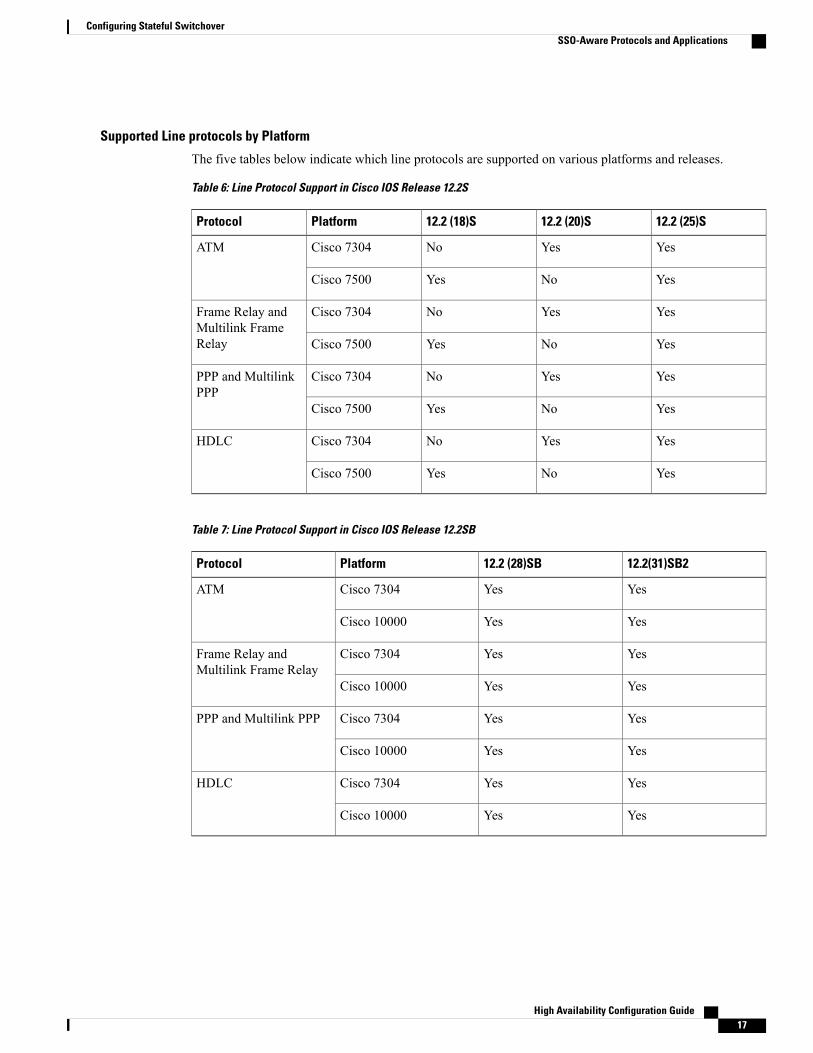
Supported Line protocols by Platform
The five tables below indicate which line protocols are supported on various platforms and releases.
Table 6: Line Protocol Support in Cisco IOS Release 12.2S
12.2 (25)S12.2 (20)S12.2 (18)SPlatformProtocol
YesYesNoCisco 7304ATM
YesNoYesCisco 7500
YesYesNoCisco 7304Frame Relay andMultilink FrameRelay YesNoYesCisco 7500
YesYesNoCisco 7304PPP and MultilinkPPP
YesNoYesCisco 7500
YesYesNoCisco 7304HDLC
YesNoYesCisco 7500
Table 7: Line Protocol Support in Cisco IOS Release 12.2SB
12.2(31)SB212.2 (28)SBPlatformProtocol
YesYesCisco 7304ATM
YesYesCisco 10000
YesYesCisco 7304Frame Relay andMultilink Frame Relay
YesYesCisco 10000
YesYesCisco 7304PPP and Multilink PPP
YesYesCisco 10000
YesYesCisco 7304HDLC
YesYesCisco 10000
High Availability Configuration Guide 17
Configuring Stateful SwitchoverSSO-Aware Protocols and Applications
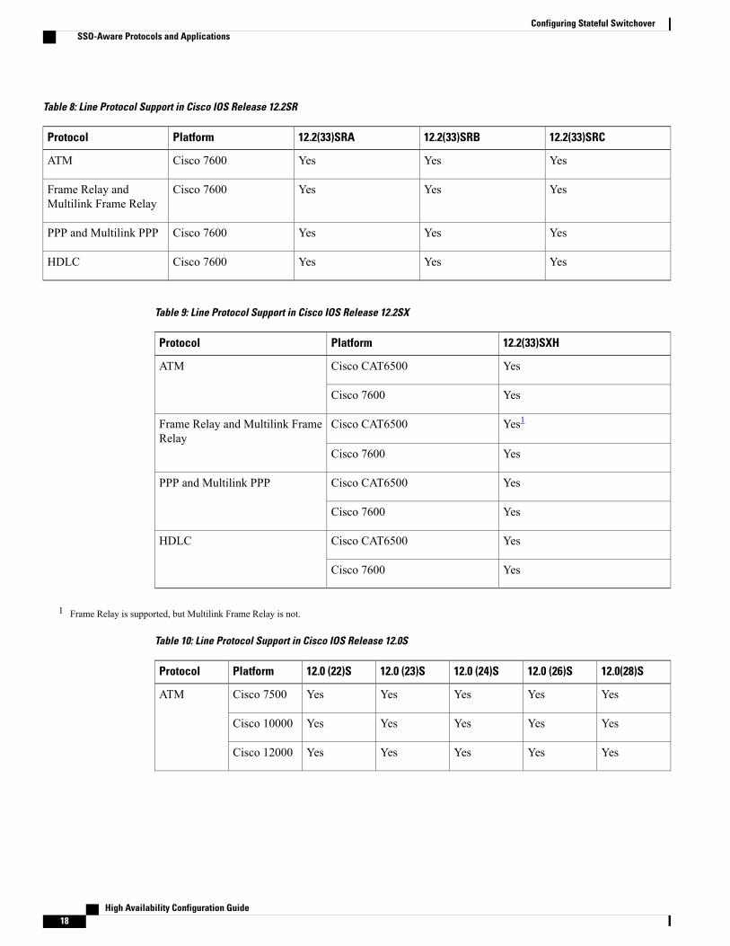
Table 8: Line Protocol Support in Cisco IOS Release 12.2SR
12.2(33)SRC12.2(33)SRB12.2(33)SRAPlatformProtocol
YesYesYesCisco 7600ATM
YesYesYesCisco 7600Frame Relay andMultilink Frame Relay
YesYesYesCisco 7600PPP and Multilink PPP
YesYesYesCisco 7600HDLC
Table 9: Line Protocol Support in Cisco IOS Release 12.2SX
12.2(33)SXHPlatformProtocol
YesCisco CAT6500ATM
YesCisco 7600
Yes1Cisco CAT6500Frame Relay and Multilink FrameRelay
YesCisco 7600
YesCisco CAT6500PPP and Multilink PPP
YesCisco 7600
YesCisco CAT6500HDLC
YesCisco 7600
1 Frame Relay is supported, but Multilink Frame Relay is not.
Table 10: Line Protocol Support in Cisco IOS Release 12.0S
12.0(28)S12.0 (26)S12.0 (24)S12.0 (23)S12.0 (22)SPlatformProtocol
YesYesYesYesYesCisco 7500ATM
YesYesYesYesYesCisco 10000
YesYesYesYesYesCisco 12000
High Availability Configuration Guide18
Configuring Stateful SwitchoverSSO-Aware Protocols and Applications
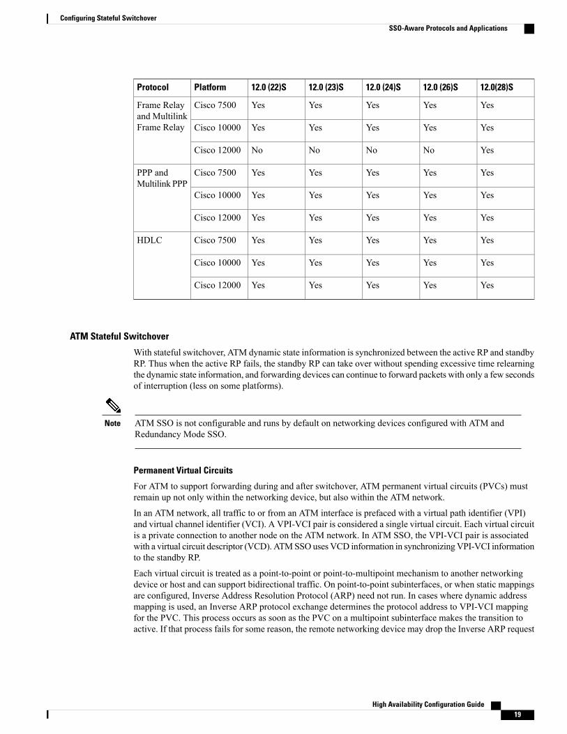
12.0(28)S12.0 (26)S12.0 (24)S12.0 (23)S12.0 (22)SPlatformProtocol
YesYesYesYesYesCisco 7500Frame Relayand MultilinkFrame Relay YesYesYesYesYesCisco 10000
YesNoNoNoNoCisco 12000
YesYesYesYesYesCisco 7500PPP andMultilink PPP
YesYesYesYesYesCisco 10000
YesYesYesYesYesCisco 12000
YesYesYesYesYesCisco 7500HDLC
YesYesYesYesYesCisco 10000
YesYesYesYesYesCisco 12000
ATM Stateful Switchover
With stateful switchover, ATM dynamic state information is synchronized between the active RP and standbyRP. Thus when the active RP fails, the standby RP can take over without spending excessive time relearningthe dynamic state information, and forwarding devices can continue to forward packets with only a few secondsof interruption (less on some platforms).
ATM SSO is not configurable and runs by default on networking devices configured with ATM andRedundancy Mode SSO.
Note
Permanent Virtual Circuits
For ATM to support forwarding during and after switchover, ATM permanent virtual circuits (PVCs) mustremain up not only within the networking device, but also within the ATM network.
In an ATM network, all traffic to or from an ATM interface is prefaced with a virtual path identifier (VPI)and virtual channel identifier (VCI). A VPI-VCI pair is considered a single virtual circuit. Each virtual circuitis a private connection to another node on the ATM network. In ATM SSO, the VPI-VCI pair is associatedwith a virtual circuit descriptor (VCD). ATMSSOuses VCD information in synchronizingVPI-VCI informationto the standby RP.
Each virtual circuit is treated as a point-to-point or point-to-multipoint mechanism to another networkingdevice or host and can support bidirectional traffic. On point-to-point subinterfaces, or when static mappingsare configured, Inverse Address Resolution Protocol (ARP) need not run. In cases where dynamic addressmapping is used, an Inverse ARP protocol exchange determines the protocol address to VPI-VCI mappingfor the PVC. This process occurs as soon as the PVC on a multipoint subinterface makes the transition toactive. If that process fails for some reason, the remote networking device may drop the Inverse ARP request
High Availability Configuration Guide 19
Configuring Stateful SwitchoverSSO-Aware Protocols and Applications
if it has not yet seen the PVC transition to active. Inverse ARP runs every 60 seconds to relearn the dynamicaddress mapping information for the active RP.
Frame Relay and Multilink Frame Relay Stateful Switchover
With stateful switchover, Frame Relay and Multilink Frame Relay dynamic state information is synchronizedbetween the active RP and standby RP. Thus when the active RP fails, the standby RP can take over withoutspending excessive time relearning the dynamic state information, and forwarding devices can continue toforward packets with only a few seconds of interruption (less on some platforms).
Permanent Virtual Circuits
For Frame Relay and Multilink Frame Relay to support forwarding during and after switchover, Frame RelayPVCs must remain up not only within the networking device, but also within the Frame Relay network.
In many cases the networking devices are connected to a switch, rather than back-to-back to another networkingdevice, and that switch is not running Cisco software. The virtual circuit state is dependent on line state. PVCsare down when the line protocol is down. PVCs are up when the line protocol is up and the PVC status reportedby the adjacent switch is active.
On point-to-point subinterfaces, or when static mappings are configured, Inverse ARP need not run. In caseswhere dynamic address mapping is used, an Inverse ARP protocol exchange determines the protocol addressto data-link connection identifier (DLCI) mapping for the PVC. This exchange occurs as soon as the multipointPVCmakes the transition to active. If the exchange fails for some reason, for example, the remote networkingdevice may drop the Inverse ARP request if it has not yet seen the PVC transition to active--any outstandingrequests are run off a timer, with a default of 60 seconds.
Keepalive Messages
A crucial factor in maintaining PVCs is the delivery of Local Management Interface (LMI) protocol messages(keepalives) during switchover. This keepalive mechanism provides an exchange of information between thenetwork server and the switch to verify that data is flowing.
If a number of consecutive LMI keepalives messages are lost or in error, the adjacent Frame Relay devicedeclares the line protocol down and all PVCs on that interface are declared down within the Frame Relaynetwork and reported as such to the remote networking device. The speed with which a switchover occurs iscrucial to avoid the loss of keepalive messages.
The line protocol state depends on the Frame Relay keepalive configuration. With keepalives disabled, theline protocol is always up as long as the hardware interface is up. With keepalives enabled, LMI protocolmessages are exchanged between the networking device and the adjacent Frame Relay switch. The line protocolis declared up after a number of consecutive successful LMI message exchanges.
The line protocol must be up according to both the networking device and the switch. The default number ofexchanges to bring up the line protocol is implementation-dependent: Three is suggested by the standards;four is used on a Cisco Frame Relay switch, taking 40 seconds at the default interval of 10 seconds; and twois used on a Cisco networking device acting as a switch or when connected back-to-back. This default numbercould be extended if the LMI “autosense” feature is being used while the LMI type expected on the switch isdetermined. The number of exchanges is configurable, although the switch and router may not have the sameowner.
The default number of lost messages or errors needed to bring down the line is three (two on a Cisco router).By default, if a loss of two messages is detected in 15 to 30 seconds, then a sequence number or LMI typeerror in the first message from the newly active RP takes the line down.
High Availability Configuration Guide20
Configuring Stateful SwitchoverSSO-Aware Protocols and Applications
If a line goes down, consecutive successful LMI protocol exchanges (default of four over 40 seconds on aCisco Frame Relay switch; default of two over 20 seconds on a Cisco device) will bring the line back upagain.
PPP and Multilink PPP Stateful Switchover
With stateful switchover, specific PPP state information is synchronized between the active RP and standbyRP. Thus when the active RP fails, the standby RP can take over without spending excessive time renegotiatingthe setup of a given link. As long as the physical link remains up, forwarding devices can continue to forwardpackets with only a few seconds of interruption (less on some platforms). Single-link PPP and Multilink PPP(MLP) sessions are maintained during RP switchover for IP connections only.
PPP and MLP support many Layer 3 protocols such as IPX and IP. Only IP links are supported in SSO. Linkssupporting non IP traffic will momentarily renegotiate and resume forwarding following a switchover. IPlinks will forward IP traffic without renegotiation.
A key factor in maintaining PPP session integrity during a switchover is the use of keepalive messages. Thiskeepalive mechanism provides an exchange of information between peer interfaces to verify data and linkintegrity. Depending on the platform and configuration, the time required for switchover to the standby RPmight exceed the keepalive timeout period. PPP keepalive messages are started when the physical link is firstbrought up. By default, keepalive messages are sent at 10-second intervals from one PPP interface to the otherPPP peer.
If five consecutive keepalive replies are not received, the PPP link would be taken down on the newly activeRP. Caution should be used when changing the keepalive interval duration to any value less than the defaultsetting.
Only in extremely rare circumstances could the RP switchover time exceed the default 50-second keepaliveduration. In the unlikely event this time is exceeded, the PPP links would renegotiate with the peers and resumeIP traffic forwarding.
PPP and MLP are not configurable and run by default on networking devices configured with SSO.Note
HDLC Stateful Switchover
With stateful switchover, High-Level Data Link Control (HDLC) synchronizes the line protocol stateinformation. Additionally, the periodic timer is restarted for interfaces that use keepalive messages to verifylink integrity. Link state information is synchronized between the active RP and standby RP. The line protocolsthat were up before the switchover remain up afterward as long as the physical interface remains up. Lineprotocols that were down remain down.
A key factor in maintaining HDLC link integrity during a switchover is the use of keepalive messages. Thiskeepalive mechanism provides an exchange of information between peer interfaces to verify data is flowing.HDLC keepalivemessages are started when the physical link is first brought up. By default, keepalivemessagesare sent at 10-second intervals from one HDLC interface to the other.
HDLCwaits at least three keepalive intervals without receiving keepalive messages, sequence number errors,or a combination of both before it declares a line protocol down. If the line protocol is down, SSO cannotsupport continuous forwarding of user session information in the event of a switchover.
High Availability Configuration Guide 21
Configuring Stateful SwitchoverSSO-Aware Protocols and Applications
HDLC is not configurable and runs by default on networking devices configured with SSO.Note
Quality of ServiceThe modular QoS CLI (MQS)-based QoS feature maintains a database of various objects created by the user,such as those used to specify traffic classes, actions for those classes in traffic policies, and attachments ofthose policies to different traffic points such as interfaces.With SSO, QoS synchronizes that database betweenthe primary and secondary RP.
IPv6 Support for Stateful SwitchoverIPv6 neighbor discovery supports SSO using Cisco Express Forwarding. When switchover occurs, the CiscoExpress Forwarding adjacency state, which is checkpointed, is used to reconstruct the neighbor discoverycache.
Line Card DriversPlatform-specific line card device drivers are bundled with the Cisco software image for SSO and are correctfor a specific image, meaning they are designed to be SSO-aware.
Line cards used with the SSO feature periodically generate status events that are forwarded to the active RP.Information includes the line up or down status, and the alarm status. This information helps SSO supportbulk synchronization after standby RP initialization and support state reconciliation and verification after aswitchover.
Line cards used with the SSO feature also have the following requirements:
• Line cards must not reset during switchover.
• Line cards must not be reconfigured.
• Subscriber sessions may not be lost.
The standby RP communicates only with the active RP, never with the line cards. This function helps toensure that the active and standby RP always have the same information.
Note
APSRPR+ and SSO support allow the automatic protection switching (APS) state to be preserved in the event offailover.
Routing Protocols and Nonstop ForwardingCisco nonstop forwarding (NSF) works with SSO to minimize the amount of time a network is unavailableto its users following a switchover. When a networking device restarts, all routing peers of that device usually
High Availability Configuration Guide22
Configuring Stateful SwitchoverSSO-Aware Protocols and Applications
detect that the device went down and then came back up. This down-to-up transition results in what is calleda “routing flap,”which could spread across multiple routing domains. Routing flaps caused by routing restartscreate routing instabilities, which are detrimental to the overall network performance. Cisco NSF helps tosuppress routing flaps, thus improving network stability.
Cisco NSF allows for the forwarding of data packets to continue along known routes while the routing protocolinformation is being restored following a switchover. With Cisco NSF, peer networking devices do notexperience routing flaps. Data traffic is forwarded through intelligent line cards while the standby RP assumescontrol from the failed active RP during a switchover. The ability of line cards to remain up through a switchoverand to be kept current with the FIB on the active RP is key to Cisco NSF operation.
A key element of Cisco NSF is packet forwarding. In Cisco networking devices, packet forwarding is providedby Cisco Express Forwarding. Cisco Express Forwarding maintains the FIB, and uses the FIB informationthat was current at the time of the switchover to continue forwarding packets during a switchover. This featureeliminates downtime during the switchover.
Cisco NSF supports the BGP, IS-IS, and OSPF routing protocols. In general, these routing protocols must beSSO-aware to detect a switchover and recover state information (converge) from peer devices. Each protocoldepends on Cisco Express Forwarding to continue forwarding packets during switchover while the routingprotocols rebuild the Routing Information Base (RIB) tables.
Network ManagementNetworkmanagement support for SSO is provided through the synchronization of specific SNMP data betweenthe active and standby RPs. From a network management perspective, this functionality helps to provide anuninterrupted management interface to the network administrator.
Synchronization of SNMP data between RPs is available only when the networking device is operatingin SSO mode.
Note
SSO for Circuit Emulation ServicesSSO for circuit emulation services (CES) for TDM pseudowires provides the ability to switch an incomingDS1/T1/E1 on one SPA to another SPA on same SIP or onto a different SIP.
How to Configure Stateful Switchover
Copying an Image onto an RP
To copy a consolidated package or subpackages onto active and standby RPs on the Cisco ASR 1000Series Router, see theCisco ASR 1000 Series Aggregation Services Routers Software Configuration Guide.
Note
High Availability Configuration Guide 23
Configuring Stateful SwitchoverHow to Configure Stateful Switchover
SUMMARY STEPS
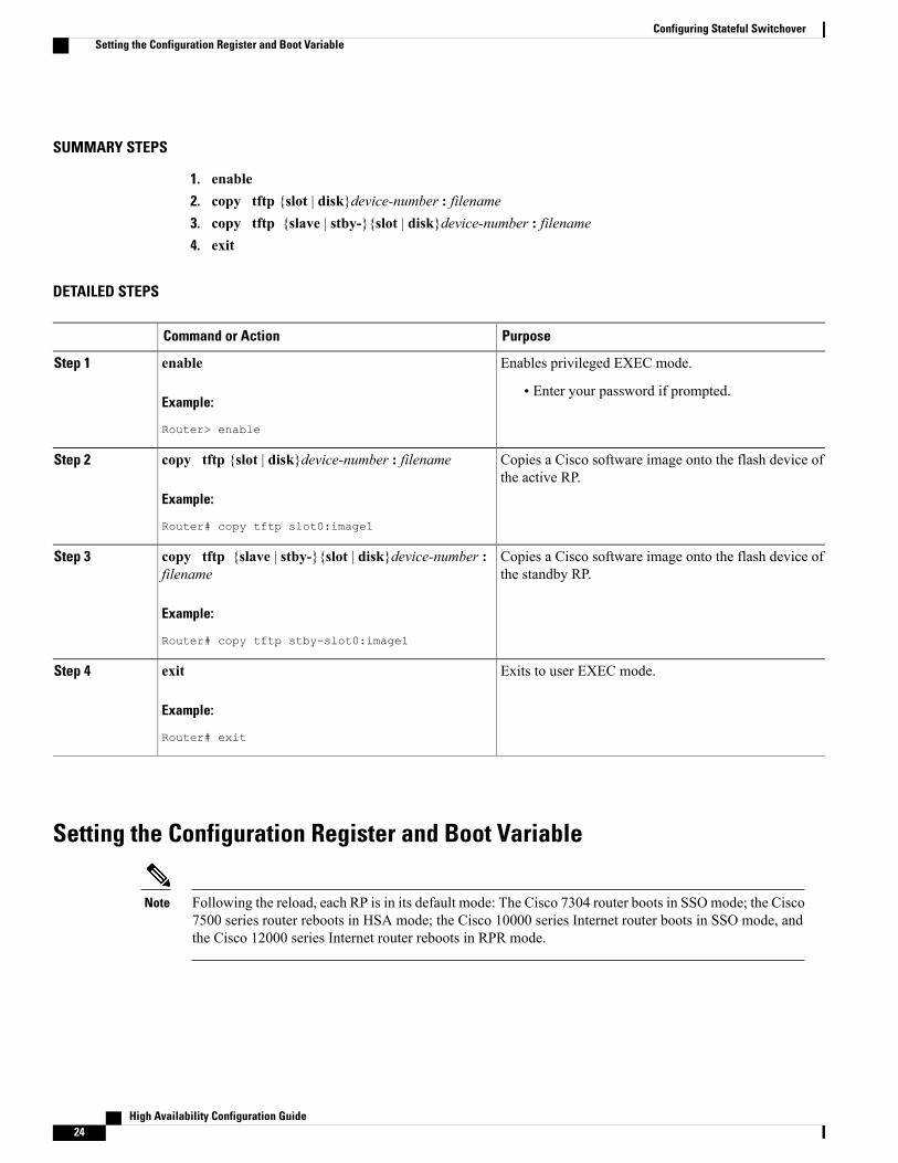
1. enable2. copy tftp {slot | disk}device-number : filename3. copy tftp {slave | stby-}{slot | disk}device-number : filename4. exit
DETAILED STEPS
PurposeCommand or Action
Enables privileged EXEC mode.enableStep 1
Example:
Router> enable
• Enter your password if prompted.
Copies a Cisco software image onto the flash device ofthe active RP.
copy tftp {slot | disk}device-number : filename
Example:
Router# copy tftp slot0:image1
Step 2
Copies a Cisco software image onto the flash device ofthe standby RP.
copy tftp {slave | stby-}{slot | disk}device-number :filename
Example:
Router# copy tftp stby-slot0:image1
Step 3
Exits to user EXEC mode.exit
Example:
Router# exit
Step 4
Setting the Configuration Register and Boot Variable
Following the reload, each RP is in its default mode: The Cisco 7304 router boots in SSOmode; the Cisco7500 series router reboots in HSA mode; the Cisco 10000 series Internet router boots in SSO mode, andthe Cisco 12000 series Internet router reboots in RPR mode.
Note
High Availability Configuration Guide24
Configuring Stateful SwitchoverSetting the Configuration Register and Boot Variable
SUMMARY STEPS
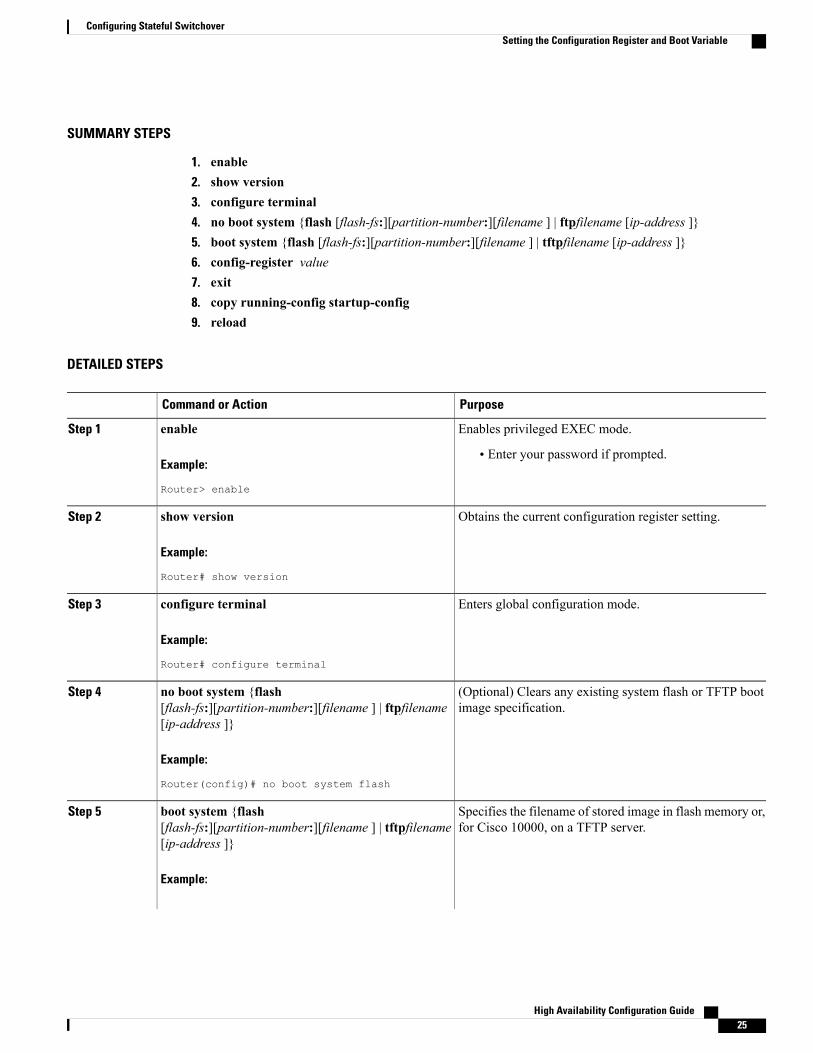
1. enable2. show version3. configure terminal4. no boot system {flash [flash-fs:][partition-number:][filename ] | ftpfilename [ip-address ]}5. boot system {flash [flash-fs:][partition-number:][filename ] | tftpfilename [ip-address ]}6. config-register value7. exit8. copy running-config startup-config9. reload
DETAILED STEPS
PurposeCommand or Action
Enables privileged EXEC mode.enableStep 1
Example:
Router> enable
• Enter your password if prompted.
Obtains the current configuration register setting.show version
Example:
Router# show version
Step 2
Enters global configuration mode.configure terminal
Example:
Router# configure terminal
Step 3
(Optional) Clears any existing system flash or TFTP bootimage specification.
no boot system {flash[flash-fs:][partition-number:][filename ] | ftpfilename[ip-address ]}
Step 4
Example:
Router(config)# no boot system flash
Specifies the filename of stored image in flash memory or,for Cisco 10000, on a TFTP server.
boot system {flash[flash-fs:][partition-number:][filename ] | tftpfilename[ip-address ]}
Step 5
Example:
High Availability Configuration Guide 25
Configuring Stateful SwitchoverSetting the Configuration Register and Boot Variable
PurposeCommand or Action
Example:
Router(config)# boot system flash
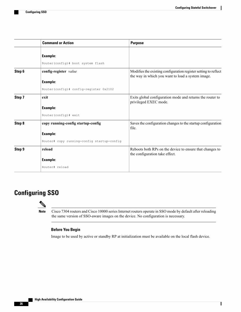
Modifies the existing configuration register setting to reflectthe way in which you want to load a system image.
config-register value
Example:
Router(config)# config-register 0x2102
Step 6
Exits global configuration mode and returns the router toprivileged EXEC mode.
exit
Example:
Router(config)# exit
Step 7
Saves the configuration changes to the startup configurationfile.
copy running-config startup-config
Example:
Router# copy running-config startup-config
Step 8
Reboots both RPs on the device to ensure that changes tothe configuration take effect.
reload
Example:
Router# reload
Step 9
Configuring SSO
Cisco 7304 routers and Cisco 10000 series Internet routers operate in SSOmode by default after reloadingthe same version of SSO-aware images on the device. No configuration is necessary.
Note
Before You Begin
Image to be used by active or standby RP at initialization must be available on the local flash device.
High Availability Configuration Guide26
Configuring Stateful SwitchoverConfiguring SSO
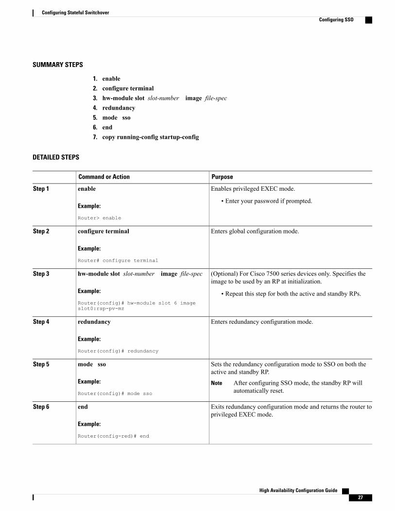
SUMMARY STEPS
1. enable2. configure terminal3. hw-module slot slot-number image file-spec4. redundancy5. mode sso6. end7. copy running-config startup-config
DETAILED STEPS
PurposeCommand or Action
Enables privileged EXEC mode.enableStep 1
Example:
Router> enable
• Enter your password if prompted.
Enters global configuration mode.configure terminal
Example:
Router# configure terminal
Step 2
(Optional) For Cisco 7500 series devices only. Specifies theimage to be used by an RP at initialization.
hw-module slot slot-number image file-spec
Example:
Router(config)# hw-module slot 6 imageslot0:rsp-pv-mz
Step 3
• Repeat this step for both the active and standby RPs.
Enters redundancy configuration mode.redundancy
Example:
Router(config)# redundancy
Step 4
Sets the redundancy configuration mode to SSO on both theactive and standby RP.
mode sso
Example:
Router(config)# mode sso
Step 5
After configuring SSO mode, the standby RP willautomatically reset.
Note
Exits redundancy configuration mode and returns the router toprivileged EXEC mode.
end
Example:
Router(config-red)# end
Step 6
High Availability Configuration Guide 27
Configuring Stateful SwitchoverConfiguring SSO
PurposeCommand or Action
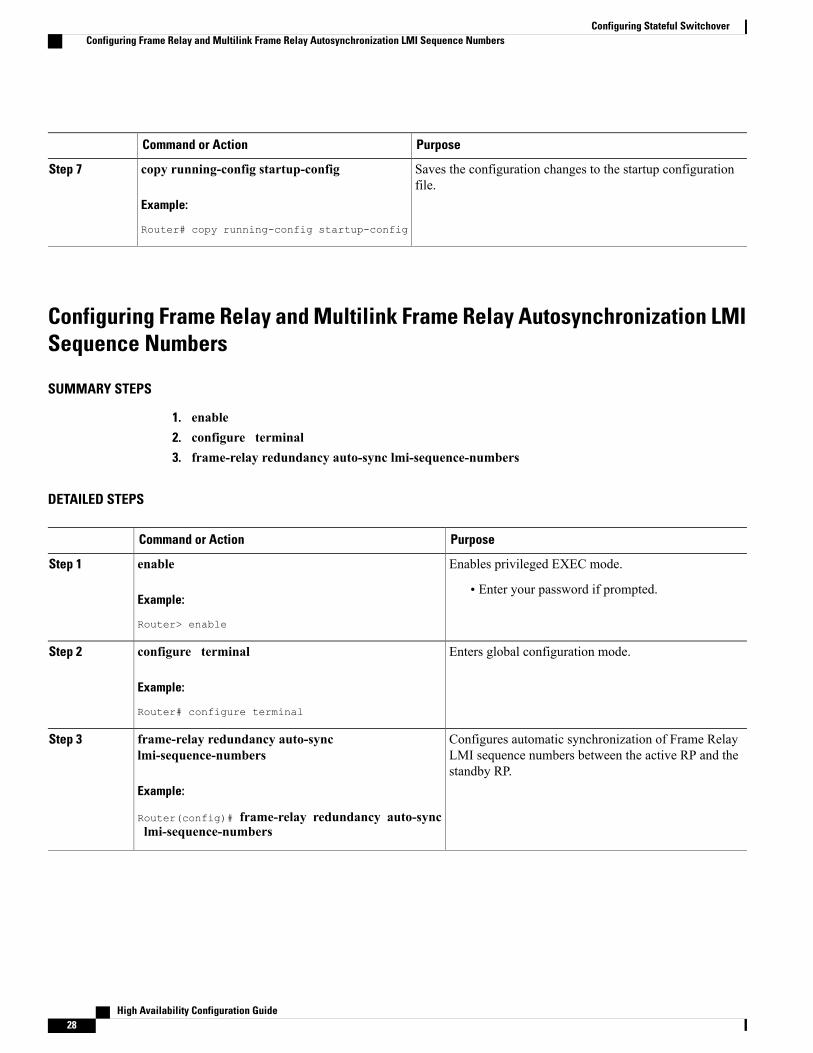
Saves the configuration changes to the startup configurationfile.
copy running-config startup-config
Example:
Router# copy running-config startup-config
Step 7
Configuring Frame Relay and Multilink Frame Relay Autosynchronization LMISequence Numbers
SUMMARY STEPS
1. enable2. configure terminal3. frame-relay redundancy auto-sync lmi-sequence-numbers
DETAILED STEPS
PurposeCommand or Action
Enables privileged EXEC mode.enableStep 1
Example:
Router> enable
• Enter your password if prompted.
Enters global configuration mode.configure terminal
Example:
Router# configure terminal
Step 2
Configures automatic synchronization of Frame RelayLMI sequence numbers between the active RP and thestandby RP.
frame-relay redundancy auto-synclmi-sequence-numbers
Example:
Router(config)# frame-relay redundancy auto-synclmi-sequence-numbers
Step 3
High Availability Configuration Guide28
Configuring Stateful SwitchoverConfiguring Frame Relay and Multilink Frame Relay Autosynchronization LMI Sequence Numbers
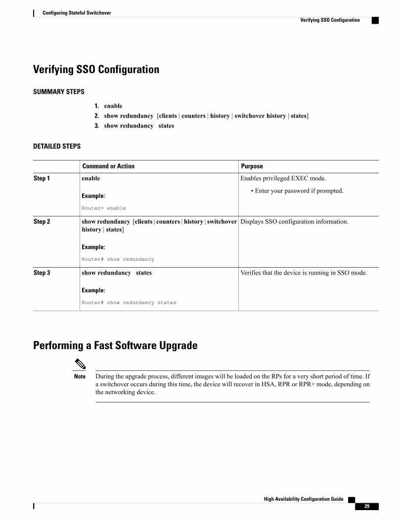
Verifying SSO Configuration
SUMMARY STEPS
1. enable2. show redundancy [clients | counters | history | switchover history | states]3. show redundancy states
DETAILED STEPS
PurposeCommand or Action
Enables privileged EXEC mode.enableStep 1
Example:
Router> enable
• Enter your password if prompted.
Displays SSO configuration information.show redundancy [clients | counters | history | switchoverhistory | states]
Step 2
Example:
Router# show redundancy
Verifies that the device is running in SSO mode.show redundancy states
Example:
Router# show redundancy states
Step 3
Performing a Fast Software Upgrade
During the upgrade process, different images will be loaded on the RPs for a very short period of time. Ifa switchover occurs during this time, the device will recover in HSA, RPR or RPR+ mode, depending onthe networking device.
Note
High Availability Configuration Guide 29
Configuring Stateful SwitchoverVerifying SSO Configuration
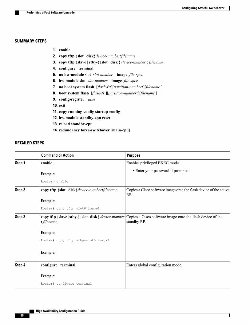
SUMMARY STEPS
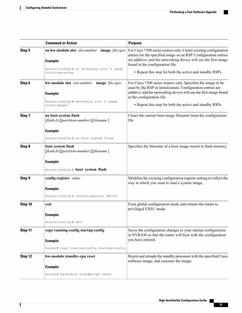
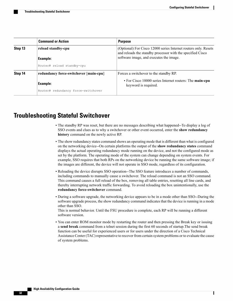
1. enable2. copy tftp {slot | disk}device-number:filename3. copy tftp {slave | stby-}{slot | disk } device-number : filename4. configure terminal5. no hw-module slot slot-number image file-spec6. hw-module slot slot-number image file-spec7. no boot system flash [flash-fs:][partition-number:][filename ]8. boot system flash [flash-fs:][partition-number:][filename ]9. config-register value10. exit11. copy running-config startup-config12. hw-module standby-cpu reset13. reload standby-cpu14. redundancy force-switchover [main-cpu]
DETAILED STEPS
PurposeCommand or Action
Enables privileged EXEC mode.enableStep 1
Example:
Router> enable
• Enter your password if prompted.
Copies a Cisco software image onto the flash device of the activeRP.
copy tftp {slot | disk}device-number:filename
Example:
Router# copy tftp slot0:image1
Step 2
Copies a Cisco software image onto the flash device of thestandby RP.
copy tftp {slave | stby-}{slot | disk } device-number: filename
Example:
Router# copy tftp stby-slot0:image1
Step 3
Example:
Enters global configuration mode.configure terminal
Example:
Router# configure terminal
Step 4
High Availability Configuration Guide30
Configuring Stateful SwitchoverPerforming a Fast Software Upgrade
PurposeCommand or Action
For Cisco 7500 series routers only. Clears existing configurationentries for the specified image on an RSP. Configuration entries
no hw-module slot slot-number image file-spec
Example:
Router(config)# no hw-module slot 6 imageslot0:rsp-pv-mz
Step 5
are additive, and the networking device will use the first imagefound in the configuration file.
• Repeat this step for both the active and standby RSPs.
For Cisco 7500 series routers only. Specifies the image to beused by the RSP at initialization. Configuration entries are
hw-module slot slot-number image file-spec
Example:
Router(config)# hw-module slot 6 imageslot0:image1
Step 6
additive, and the networking device will use the first image foundin the configuration file.
• Repeat this step for both the active and standby RSPs.
Clears the current boot image filename from the configurationfile.
no boot system flash[flash-fs:][partition-number:][filename ]
Example:
Router(config)# no boot system flash
Step 7
Specifies the filename of a boot image stored in flash memory.boot system flash[flash-fs:][partition-number:][filename ]
Step 8
Example:
Router(config)# boot system flash
Modifies the existing configuration register setting to reflect theway in which you want to load a system image.
config-register value
Example:
Router(config)# config-register 0x2102
Step 9
Exits global configuration mode and returns the router toprivileged EXEC mode.
exit
Example:
Router(config)# exit
Step 10
Saves the configuration changes to your startup configurationin NVRAM so that the router will boot with the configurationyou have entered.
copy running-config startup-config
Example:
Router# copy running-config startup-config
Step 11
Resets and reloads the standby processor with the specified Ciscosoftware image, and executes the image.
hw-module standby-cpu reset
Example:
Router# hw-module standby-cpu reset
Step 12
High Availability Configuration Guide 31
Configuring Stateful SwitchoverPerforming a Fast Software Upgrade
PurposeCommand or Action
(Optional) For Cisco 12000 series Internet routers only. Resetsand reloads the standby processor with the specified Ciscosoftware image, and executes the image.
reload standby-cpu
Example:
Router# reload standby-cpu
Step 13
Forces a switchover to the standby RP.redundancy force-switchover [main-cpu]Step 14
Example:
Router# redundancy force-switchover
• For Cisco 10000 series Internet routers: Themain-cpukeyword is required.
Troubleshooting Stateful Switchover• The standby RP was reset, but there are no messages describing what happened--To display a log ofSSO events and clues as to why a switchover or other event occurred, enter the show redundancyhistory command on the newly active RP.
• The show redundancy states command shows an operating mode that is different than what is configuredon the networking device--On certain platforms the output of the show redundancy states commanddisplays the actual operating redundancy mode running on the device, and not the configured mode asset by the platform. The operating mode of the system can change depending on system events. Forexample, SSO requires that both RPs on the networking device be running the same software image; ifthe images are different, the device will not operate in SSO mode, regardless of its configuration.
• Reloading the device disrupts SSO operation--The SSO feature introduces a number of commands,including commands to manually cause a switchover. The reload command is not an SSO command.This command causes a full reload of the box, removing all table entries, resetting all line cards, andthereby interrupting network traffic forwarding. To avoid reloading the box unintentionally, use theredundancy force-switchover command.
• During a software upgrade, the networking device appears to be in a mode other than SSO--During thesoftware upgrade process, the show redundancy command indicates that the device is running in a modeother than SSO.This is normal behavior. Until the FSU procedure is complete, each RP will be running a differentsoftware version.
• You can enter ROM monitor mode by restarting the router and then pressing the Break key or issuinga send break command from a telnet session during the first 60 seconds of startup.The send breakfunction can be useful for experienced users or for users under the direction of a Cisco TechnicalAssistance Center (TAC) representative to recover from certain system problems or to evaluate the causeof system problems.
High Availability Configuration Guide32
Configuring Stateful SwitchoverTroubleshooting Stateful Switchover
Troubleshooting SSO
SUMMARY STEPS
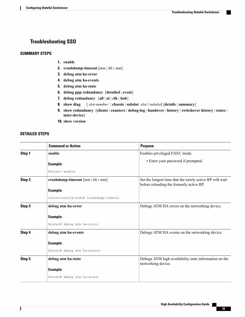
1. enable2. crashdump-timeout [mm | hh : mm]3. debug atm ha-error4. debug atm ha-events5. debug atm ha-state6. debug ppp redundancy [detailed | event]7. debug redundancy {all | ui | clk | hub}8. show diag [ slot-number | chassis | subslot slot / subslot] [details | summary]9. show redundancy [clients | counters | debug-log | handover | history | switchover history | states |
inter-device]10. show version
DETAILED STEPS
PurposeCommand or Action
Enables privileged EXEC mode.enableStep 1
Example:
Router> enable
• Enter your password if prompted.
Set the longest time that the newly active RP will waitbefore reloading the formerly active RP.
crashdump-timeout [mm | hh : mm]
Example:
router(config-red)# crashdump-timeout
Step 2
Debugs ATM HA errors on the networking device.debug atm ha-error
Example:
Router# debug atm ha-error
Step 3
Debugs ATM HA events on the networking device.debug atm ha-events
Example:
Router# debug atm ha-events
Step 4
Debugs ATM high-availability state information on thenetworking device.
debug atm ha-state
Example:
Router# debug atm ha-state
Step 5
High Availability Configuration Guide 33
Configuring Stateful SwitchoverTroubleshooting Stateful Switchover
PurposeCommand or Action
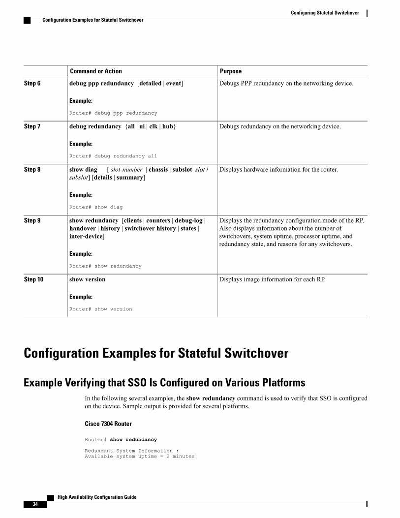
Debugs PPP redundancy on the networking device.debug ppp redundancy [detailed | event]
Example:
Router# debug ppp redundancy
Step 6
Debugs redundancy on the networking device.debug redundancy {all | ui | clk | hub}
Example:
Router# debug redundancy all
Step 7
Displays hardware information for the router.show diag [ slot-number | chassis | subslot slot /subslot] [details | summary]
Step 8
Example:
Router# show diag
Displays the redundancy configuration mode of the RP.Also displays information about the number of
show redundancy [clients | counters | debug-log |handover | history | switchover history | states |inter-device]
Step 9
switchovers, system uptime, processor uptime, andredundancy state, and reasons for any switchovers.
Example:
Router# show redundancy
Displays image information for each RP.show version
Example:
Router# show version
Step 10
Configuration Examples for Stateful Switchover
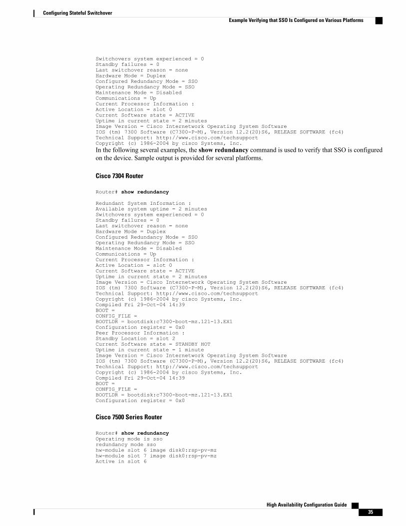
Example Verifying that SSO Is Configured on Various PlatformsIn the following several examples, the show redundancy command is used to verify that SSO is configuredon the device. Sample output is provided for several platforms.
Cisco 7304 Router
Router# show redundancy
Redundant System Information :Available system uptime = 2 minutes
High Availability Configuration Guide34
Configuring Stateful SwitchoverConfiguration Examples for Stateful Switchover
Switchovers system experienced = 0Standby failures = 0Last switchover reason = noneHardware Mode = DuplexConfigured Redundancy Mode = SSOOperating Redundancy Mode = SSOMaintenance Mode = DisabledCommunications = UpCurrent Processor Information :Active Location = slot 0Current Software state = ACTIVEUptime in current state = 2 minutesImage Version = Cisco Internetwork Operating System SoftwareIOS (tm) 7300 Software (C7300-P-M), Version 12.2(20)S6, RELEASE SOFTWARE (fc4)Technical Support: http://www.cisco.com/techsupportCopyright (c) 1986-2004 by cisco Systems, Inc.In the following several examples, the show redundancy command is used to verify that SSO is configuredon the device. Sample output is provided for several platforms.
Cisco 7304 Router
Router# show redundancy
Redundant System Information :Available system uptime = 2 minutesSwitchovers system experienced = 0Standby failures = 0Last switchover reason = noneHardware Mode = DuplexConfigured Redundancy Mode = SSOOperating Redundancy Mode = SSOMaintenance Mode = DisabledCommunications = UpCurrent Processor Information :Active Location = slot 0Current Software state = ACTIVEUptime in current state = 2 minutesImage Version = Cisco Internetwork Operating System SoftwareIOS (tm) 7300 Software (C7300-P-M), Version 12.2(20)S6, RELEASE SOFTWARE (fc4)Technical Support: http://www.cisco.com/techsupportCopyright (c) 1986-2004 by cisco Systems, Inc.Compiled Fri 29-Oct-04 14:39BOOT =CONFIG_FILE =BOOTLDR = bootdisk:c7300-boot-mz.121-13.EX1Configuration register = 0x0Peer Processor Information :Standby Location = slot 2Current Software state = STANDBY HOTUptime in current state = 1 minuteImage Version = Cisco Internetwork Operating System SoftwareIOS (tm) 7300 Software (C7300-P-M), Version 12.2(20)S6, RELEASE SOFTWARE (fc4)Technical Support: http://www.cisco.com/techsupportCopyright (c) 1986-2004 by cisco Systems, Inc.Compiled Fri 29-Oct-04 14:39BOOT =CONFIG_FILE =BOOTLDR = bootdisk:c7300-boot-mz.121-13.EX1Configuration register = 0x0
Cisco 7500 Series Router
Router# show redundancyOperating mode is ssoredundancy mode ssohw-module slot 6 image disk0:rsp-pv-mzhw-module slot 7 image disk0:rsp-pv-mzActive in slot 6
High Availability Configuration Guide 35
Configuring Stateful SwitchoverExample Verifying that SSO Is Configured on Various Platforms
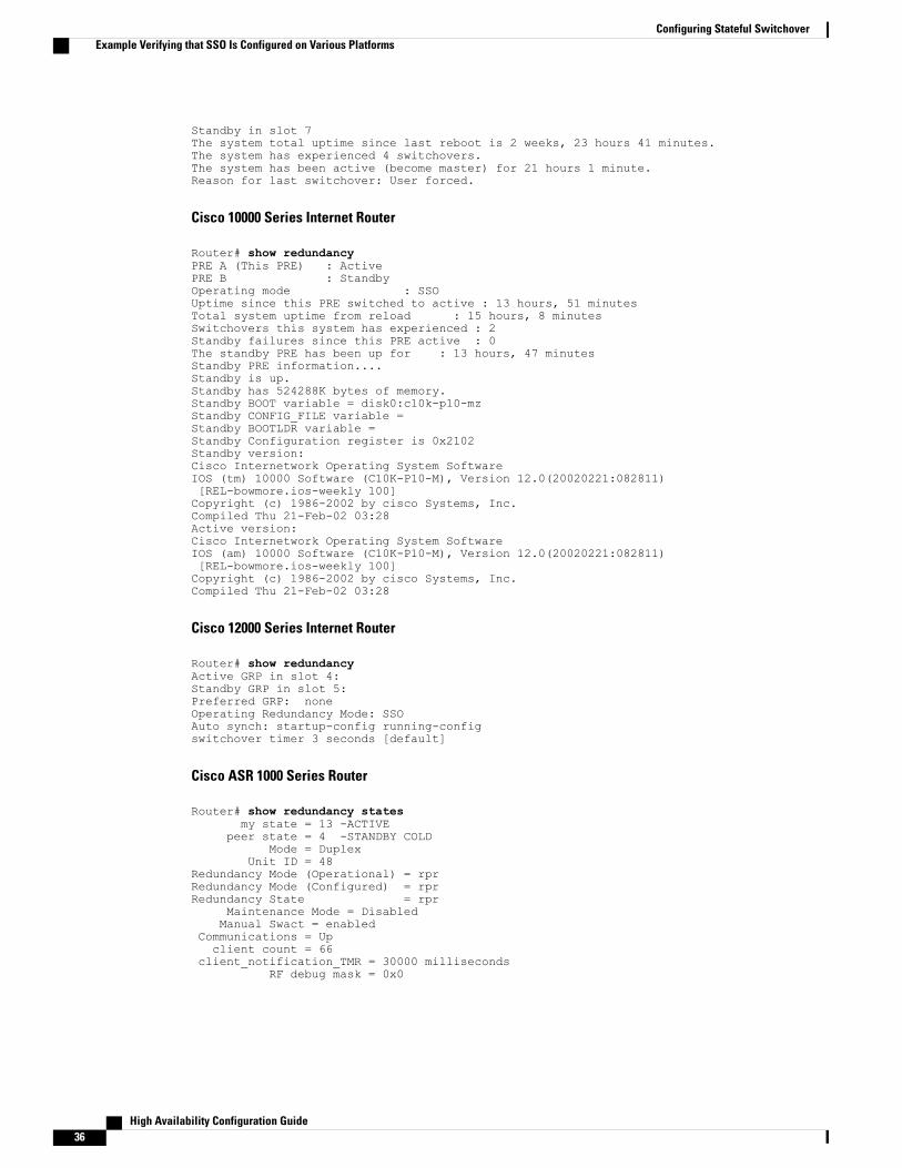
Standby in slot 7The system total uptime since last reboot is 2 weeks, 23 hours 41 minutes.The system has experienced 4 switchovers.The system has been active (become master) for 21 hours 1 minute.Reason for last switchover: User forced.
Cisco 10000 Series Internet Router
Router# show redundancyPRE A (This PRE) : ActivePRE B : StandbyOperating mode : SSOUptime since this PRE switched to active : 13 hours, 51 minutesTotal system uptime from reload : 15 hours, 8 minutesSwitchovers this system has experienced : 2Standby failures since this PRE active : 0The standby PRE has been up for : 13 hours, 47 minutesStandby PRE information....Standby is up.Standby has 524288K bytes of memory.Standby BOOT variable = disk0:c10k-p10-mzStandby CONFIG_FILE variable =Standby BOOTLDR variable =Standby Configuration register is 0x2102Standby version:Cisco Internetwork Operating System SoftwareIOS (tm) 10000 Software (C10K-P10-M), Version 12.0(20020221:082811)[REL-bowmore.ios-weekly 100]Copyright (c) 1986-2002 by cisco Systems, Inc.Compiled Thu 21-Feb-02 03:28Active version:Cisco Internetwork Operating System SoftwareIOS (am) 10000 Software (C10K-P10-M), Version 12.0(20020221:082811)[REL-bowmore.ios-weekly 100]Copyright (c) 1986-2002 by cisco Systems, Inc.Compiled Thu 21-Feb-02 03:28
Cisco 12000 Series Internet Router
Router# show redundancyActive GRP in slot 4:Standby GRP in slot 5:Preferred GRP: noneOperating Redundancy Mode: SSOAuto synch: startup-config running-configswitchover timer 3 seconds [default]
Cisco ASR 1000 Series Router
Router# show redundancy statesmy state = 13 -ACTIVE
peer state = 4 -STANDBY COLDMode = Duplex
Unit ID = 48Redundancy Mode (Operational) = rprRedundancy Mode (Configured) = rprRedundancy State = rpr
Maintenance Mode = DisabledManual Swact = enabled
Communications = Upclient count = 66
client_notification_TMR = 30000 millisecondsRF debug mask = 0x0
High Availability Configuration Guide36
Configuring Stateful SwitchoverExample Verifying that SSO Is Configured on Various Platforms
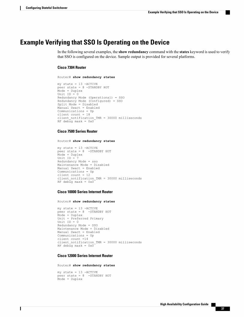
Example Verifying that SSO Is Operating on the DeviceIn the following several examples, the show redundancy command with the states keyword is used to verifythat SSO is configured on the device. Sample output is provided for several platforms.
Cisco 7304 Router
Router# show redundancy states
my state = 13 -ACTIVEpeer state = 8 -STANDBY HOTMode = DuplexUnit ID = 0Redundancy Mode (Operational) = SSORedundancy Mode (Configured) = SSOSplit Mode = DisabledManual Swact = EnabledCommunications = Upclient count = 18client_notification_TMR = 30000 millisecondsRF debug mask = 0x0
Cisco 7500 Series Router
Router# show redundancy states
my state = 13 -ACTIVEpeer state = 8 -STANDBY HOTMode = DuplexUnit ID = 7Redundancy Mode = ssoMaintenance Mode = DisabledManual Swact = EnabledCommunications = Upclient count = 12client_notification_TMR = 30000 millisecondsRF debug mask = 0x0
Cisco 10000 Series Internet Router
Router# show redundancy states
my state = 13 -ACTIVEpeer state = 8 -STANDBY HOTMode = DuplexUnit = Preferred PrimaryUnit ID = 0Redundancy Mode = SSOMaintenance Mode = DisabledManual Swact = EnabledCommunications = Upclient count =14client_notification_TMR = 30000 millisecondsRF debug mask = 0x0
Cisco 12000 Series Internet Router
Router# show redundancy states
my state = 13 -ACTIVEpeer state = 8 -STANDBY HOTMode = Duplex
High Availability Configuration Guide 37
Configuring Stateful SwitchoverExample Verifying that SSO Is Operating on the Device
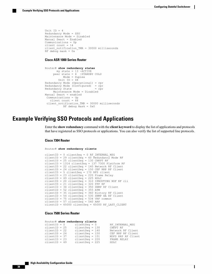
Unit ID = 4Redundancy Mode = SSOMaintenance Mode = DisabledManual Swact = EnabledCommunications = Upclient count = 14client_notification_TMR = 30000 millisecondsRF debug mask = 0x
Cisco ASR 1000 Series Router
Router# show redundancy statesmy state = 13 -ACTIVE
peer state = 4 -STANDBY COLDMode = Duplex
Unit ID = 48Redundancy Mode (Operational) = rprRedundancy Mode (Configured) = rprRedundancy State = rpr
Maintenance Mode = DisabledManual Swact = enabledCommunications = Upclient count = 66
client_notification_TMR = 30000 millisecondsRF debug mask = 0x0
Example Verifying SSO Protocols and ApplicationsEnter the show redundancy commandwith the client keyword to display the list of applications and protocolsthat have registered as SSO protocols or applications. You can also verify the list of supported line protocols.
Cisco 7304 Router
Router# show redundancy clients
clientID = 0 clientSeq = 0 RF_INTERNAL_MSGclientID = 29 clientSeq = 60 Redundancy Mode RFclientID = 25 clientSeq = 130 CHKPT RFclientID = 1314 clientSeq = 137 7300 Platform RFclientID = 22 clientSeq = 140 Network RF ClientclientID = 24 clientSeq = 150 CEF RRP RF ClientclientID = 5 clientSeq = 170 RFS clientclientID = 23 clientSeq = 220 Frame RelayclientID = 49 clientSeq = 225 HDLCclientID = 20 clientSeq = 310 IPROUTING NSF RF cliclientID = 21 clientSeq = 320 PPP RFclientID = 34 clientSeq = 350 SNMP RF ClientclientID = 52 clientSeq = 355 ATMclientID = 35 clientSeq = 360 History RF ClientclientID = 54 clientSeq = 530 SNMP HA RF ClientclientID = 75 clientSeq = 534 VRF commonclientID = 57 clientSeq = 540 ARPclientID = 65000 clientSeq = 65000 RF_LAST_CLIENT
Cisco 7500 Series Router
Router# show redundancy clientsclientID = 0 clientSeq = 0 RF_INTERNAL_MSGclientID = 25 clientSeq = 130 CHKPT RFclientID = 22 clientSeq = 140 Network RF ClientclientID = 24 clientSeq = 150 CEF RRP RF ClientclientID = 37 clientSeq = 151 MDFS RRP RF ClientclientID = 23 clientSeq = 220 FRAME RELAYclientID = 49 clientSeq = 225 HDLC
High Availability Configuration Guide38
Configuring Stateful SwitchoverExample Verifying SSO Protocols and Applications

clientID = 20 clientSeq = 310 IPROUTING NSF RF cliclientID = 21 clientSeq = 320 PPP RFclientID = 34 clientSeq = 330 SNMP RF ClientclientID = 29 clientSeq = 340 ATMclientID = 35 clientSeq = 350 History RF ClientclientID = 50 clientSeq = 530 SNMP HA RF ClientclientID = 65000 clientSeq = 65000 RF_LAST_CLIENT
Cisco 10000 Series Internet Routere
Router# show redundancy clientsclientID = 0 clientSeq = 0 RF_INTERNAL_MSGclientID = 25 clientSeq = 130 CHKPT RFclientID = 22 clientSeq = 140 Network RF ClientclientID = 24 clientSeq = 150 CEF RRP RF ClientclientID = 26 clientSeq = 160 C10K RF ClientclientID = 5 clientSeq = 170 RFS clientclientID = 23 clientSeq = 220 Frame RelayclientID = 49 clientSeq = 225 HDLCclientID = 20 clientSeq = 310 IPROUTING NSF RF cliclientID = 21 clientSeq = 320 PPP RFclientID = 34 clientSeq = 330 SNMP RF ClientclientID = 29 clientSeq = 340 ATMclientID = 35 clientSeq = 350 History RF ClientclientID = 65000 clientSeq = 65000 RF_LAST_CLIENT
Cisco 12000 Series Internet Router
Router# show redundancy clientsclientID = 0 clientSeq = 0 RF_INTERNAL_MSGclientID = 25 clientSeq = 130 CHKPT RFclientID = 27 clientSeq = 132 C12K RF COMMON ClientclientID = 30 clientSeq = 135 Redundancy Mode RFclientID = 22 clientSeq = 140 Network RF ClientclientID = 24 clientSeq = 150 CEF RRP RF ClientclientID = 37 clientSeq = 151 MDFS RRP RF ClientclientID = 5 clientSeq = 170 RFS clientclientID = 23 clientSeq = 220 Frame RelayclientID = 49 clientSeq = 225 HDLCclientID = 20 clientSeq = 310 IPROUTING NSF RF cliclientID = 21 clientSeq = 320 PPP RFclientID = 34 clientSeq = 330 SNMP RF ClientclientID = 29 clientSeq = 340 ATMclientID = 35 clientSeq = 350 History RF ClientclientID = 50 clientSeq = 530 SNMP HA RF ClientclientID = 65000 clientSeq = 65000 RF_LAST_CLIENT
Cisco ASR 1000 Series Router
Router# show redundancy clientsclientID = 0 clientSeq = 0 RF_INTERNAL_MSGclientID = 29 clientSeq = 60 Redundancy Mode RFclientID = 139 clientSeq = 62 IfIndexclientID = 25 clientSeq = 69 CHKPT RFclientID = 1340 clientSeq = 90 ASR1000-RP PlatformclientID = 1501 clientSeq = 91 Cat6k CWAN HAclientID = 78 clientSeq = 95 TSPTUN HAclientID = 305 clientSeq = 96 Multicast ISSU ConsoclientID = 304 clientSeq = 97 IP multicast RF ClieclientID = 22 clientSeq = 98 Network RF ClientclientID = 88 clientSeq = 99 HSRPclientID = 114 clientSeq = 100 GLBPclientID = 1341 clientSeq = 102 ASR1000 DPIDXclientID = 1505 clientSeq = 103 Cat6k SPA TSMclientID = 1344 clientSeq = 110 ASR1000-RP SBC RFclientID = 227 clientSeq = 111 SBC RFclientID = 71 clientSeq = 112 XDR RRP RF Client
High Availability Configuration Guide 39
Configuring Stateful SwitchoverExample Verifying SSO Protocols and Applications
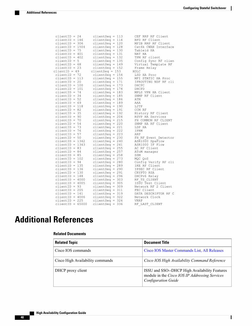
clientID = 24 clientSeq = 113 CEF RRP RF ClientclientID = 146 clientSeq = 114 BFD RF ClientclientID = 306 clientSeq = 120 MFIB RRP RF ClientclientID = 1504 clientSeq = 128 Cat6k CWAN InterfaceclientID = 75 clientSeq = 130 Tableid HAclientID = 401 clientSeq = 131 NAT HAclientID = 402 clientSeq = 132 TPM RF clientclientID = 5 clientSeq = 135 Config Sync RF clienclientID = 68 clientSeq = 149 Virtual Template RFclientID = 23 clientSeq = 152 Frame RelayclientID = 49 clientSeq = 153 HDLCclientID = 72 clientSeq = 154 LSD HA ProcclientID = 113 clientSeq = 155 MFI STATIC HA ProcclientID = 20 clientSeq = 171 IPROUTING NSF RF cliclientID = 100 clientSeq = 173 DHCPCclientID = 101 clientSeq = 174 DHCPDclientID = 74 clientSeq = 183 MPLS VPN HA ClientclientID = 34 clientSeq = 185 SNMP RF ClientclientID = 52 clientSeq = 186 ATMclientID = 69 clientSeq = 189 AAAclientID = 118 clientSeq = 190 L2TPclientID = 82 clientSeq = 191 CCM RFclientID = 35 clientSeq = 192 History RF ClientclientID = 90 clientSeq = 204 RSVP HA ServicesclientID = 70 clientSeq = 215 FH COMMON RF CLIENTclientID = 54 clientSeq = 220 SNMP HA RF ClientclientID = 73 clientSeq = 221 LDP HAclientID = 76 clientSeq = 222 IPRMclientID = 57 clientSeq = 223 ARPclientID = 50 clientSeq = 230 FH_RF_Event_DetectorclientID = 1342 clientSeq = 240 ASR1000 SpaFlowclientID = 1343 clientSeq = 241 ASR1000 IF FlowclientID = 83 clientSeq = 255 AC RF ClientclientID = 84 clientSeq = 257 AToM managerclientID = 85 clientSeq = 258 SSMclientID = 102 clientSeq = 273 MQC QoSclientID = 94 clientSeq = 280 Config Verify RF cliclientID = 135 clientSeq = 289 IKE RF ClientclientID = 136 clientSeq = 290 IPSEC RF ClientclientID = 130 clientSeq = 291 CRYPTO RSAclientID = 148 clientSeq = 296 DHCPv6 RelayclientID = 4000 clientSeq = 303 RF_TS_CLIENTclientID = 4005 clientSeq = 305 ISSU Test ClientclientID = 93 clientSeq = 309 Network RF 2 ClientclientID = 205 clientSeq = 311 FEC ClientclientID = 141 clientSeq = 319 DATA DESCRIPTOR RF CclientID = 4006 clientSeq = 322 Network ClockclientID = 225 clientSeq = 326 VRRPclientID = 65000 clientSeq = 336 RF_LAST_CLIENT
Additional ReferencesRelated Documents
Document TitleRelated Topic
Cisco IOS Master Commands List, All ReleasesCisco IOS commands
Cisco IOS High Availability Command ReferenceCisco High Availability commands
ISSU and SSO--DHCP High Availability Featuresmodule in the Cisco IOS IP Addressing ServicesConfiguration Guide
DHCP proxy client
High Availability Configuration Guide40
Configuring Stateful SwitchoverAdditional References
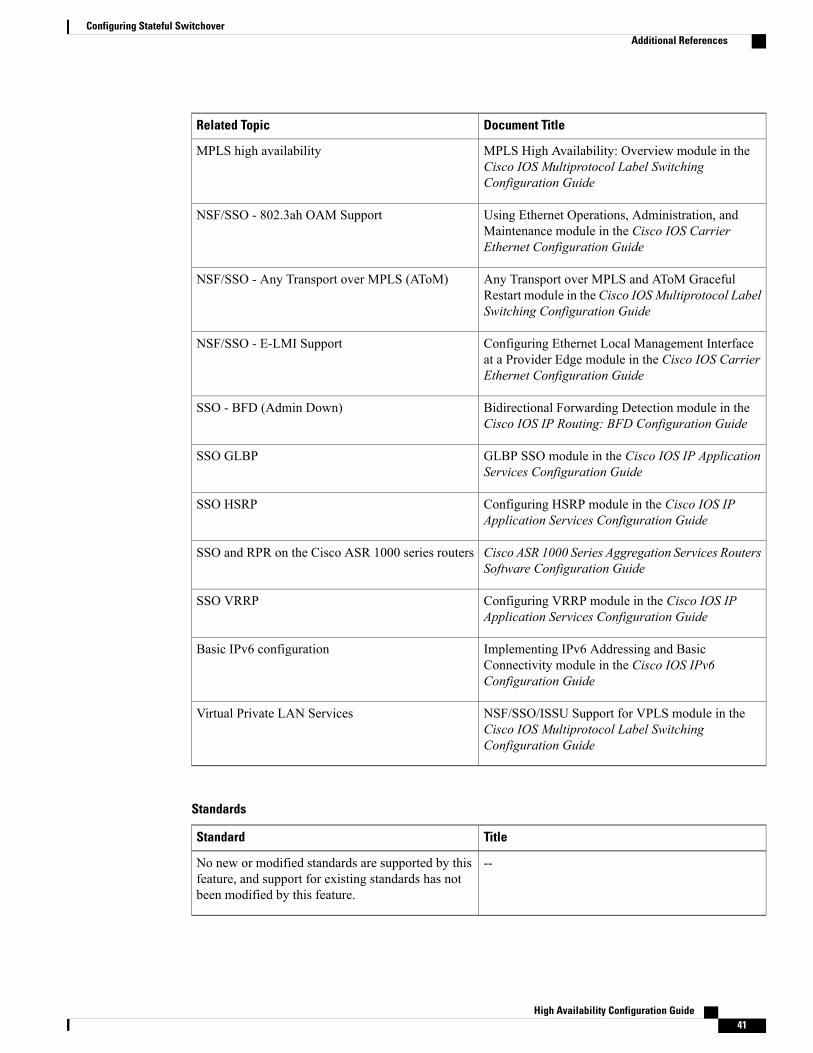
Document TitleRelated Topic
MPLS High Availability: Overview module in theCisco IOS Multiprotocol Label SwitchingConfiguration Guide
MPLS high availability
Using Ethernet Operations, Administration, andMaintenance module in the Cisco IOS CarrierEthernet Configuration Guide
NSF/SSO - 802.3ah OAM Support
Any Transport over MPLS and AToM GracefulRestart module in the Cisco IOSMultiprotocol LabelSwitching Configuration Guide
NSF/SSO - Any Transport over MPLS (AToM)
Configuring Ethernet Local Management Interfaceat a Provider Edge module in the Cisco IOS CarrierEthernet Configuration Guide
NSF/SSO - E-LMI Support
Bidirectional Forwarding Detection module in theCisco IOS IP Routing: BFD Configuration Guide
SSO - BFD (Admin Down)
GLBP SSO module in the Cisco IOS IP ApplicationServices Configuration Guide
SSO GLBP
Configuring HSRP module in the Cisco IOS IPApplication Services Configuration Guide
SSO HSRP
Cisco ASR 1000 Series Aggregation Services RoutersSoftware Configuration Guide
SSO and RPR on the Cisco ASR 1000 series routers
Configuring VRRP module in the Cisco IOS IPApplication Services Configuration Guide
SSO VRRP
Implementing IPv6 Addressing and BasicConnectivity module in the Cisco IOS IPv6Configuration Guide
Basic IPv6 configuration
NSF/SSO/ISSU Support for VPLS module in theCisco IOS Multiprotocol Label SwitchingConfiguration Guide
Virtual Private LAN Services
Standards
TitleStandard
--No new or modified standards are supported by thisfeature, and support for existing standards has notbeen modified by this feature.
High Availability Configuration Guide 41
Configuring Stateful SwitchoverAdditional References
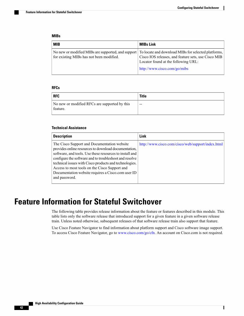
MIBs
MIBs LinkMIB
To locate and downloadMIBs for selected platforms,Cisco IOS releases, and feature sets, use Cisco MIBLocator found at the following URL:
http://www.cisco.com/go/mibs
No new or modifiedMIBs are supported, and supportfor existing MIBs has not been modified.
RFCs
TitleRFC
--No new or modified RFCs are supported by thisfeature.
Technical Assistance
LinkDescription
http://www.cisco.com/cisco/web/support/index.htmlThe Cisco Support and Documentation websiteprovides online resources to download documentation,software, and tools. Use these resources to install andconfigure the software and to troubleshoot and resolvetechnical issues with Cisco products and technologies.Access to most tools on the Cisco Support andDocumentation website requires a Cisco.com user IDand password.
Feature Information for Stateful SwitchoverThe following table provides release information about the feature or features described in this module. Thistable lists only the software release that introduced support for a given feature in a given software releasetrain. Unless noted otherwise, subsequent releases of that software release train also support that feature.
Use Cisco Feature Navigator to find information about platform support and Cisco software image support.To access Cisco Feature Navigator, go to www.cisco.com/go/cfn. An account on Cisco.com is not required.
High Availability Configuration Guide42
Configuring Stateful SwitchoverFeature Information for Stateful Switchover

Table 11: Feature Information for Cisco Stateful Switchover
Feature InformationReleasesFeature Name
12.0(22)S 12.0(23)S 12.0(24)S12.2(20)S 12.2(18)S 12.2(33)SRA
Stateful Switchover (SSO)
High Availability Configuration Guide 43
Configuring Stateful SwitchoverFeature Information for Stateful Switchover
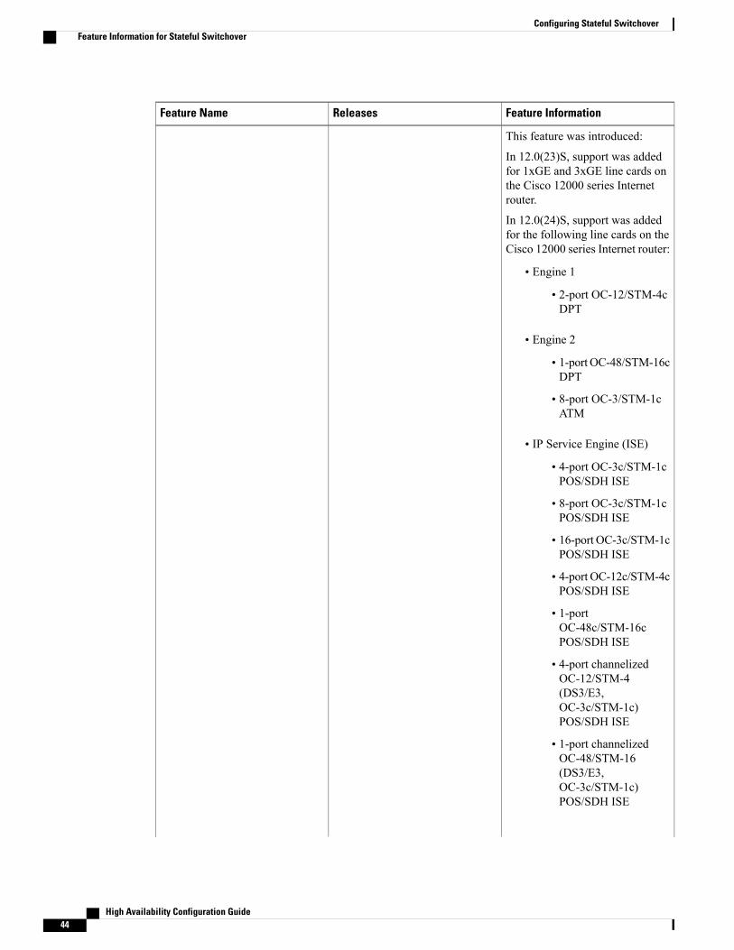
Feature InformationReleasesFeature Name
This feature was introduced:
In 12.0(23)S, support was addedfor 1xGE and 3xGE line cards onthe Cisco 12000 series Internetrouter.
In 12.0(24)S, support was addedfor the following line cards on theCisco 12000 series Internet router:
• Engine 1
• 2-port OC-12/STM-4cDPT
• Engine 2
• 1-port OC-48/STM-16cDPT
• 8-port OC-3/STM-1cATM
• IP Service Engine (ISE)
• 4-port OC-3c/STM-1cPOS/SDH ISE
• 8-port OC-3c/STM-1cPOS/SDH ISE
• 16-port OC-3c/STM-1cPOS/SDH ISE
• 4-port OC-12c/STM-4cPOS/SDH ISE
• 1-portOC-48c/STM-16cPOS/SDH ISE
• 4-port channelizedOC-12/STM-4(DS3/E3,OC-3c/STM-1c)POS/SDH ISE
• 1-port channelizedOC-48/STM-16(DS3/E3,OC-3c/STM-1c)POS/SDH ISE
High Availability Configuration Guide44
Configuring Stateful SwitchoverFeature Information for Stateful Switchover
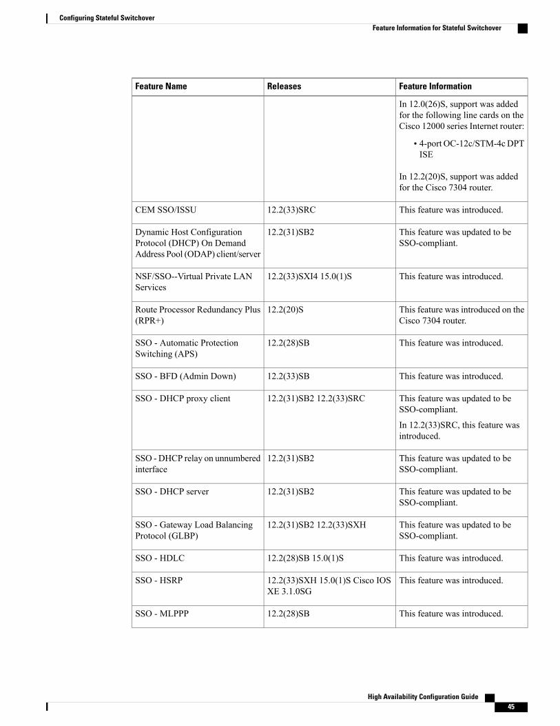
Feature InformationReleasesFeature Name
In 12.0(26)S, support was addedfor the following line cards on theCisco 12000 series Internet router:
• 4-port OC-12c/STM-4cDPTISE
In 12.2(20)S, support was addedfor the Cisco 7304 router.
This feature was introduced.12.2(33)SRCCEM SSO/ISSU
This feature was updated to beSSO-compliant.
12.2(31)SB2Dynamic Host ConfigurationProtocol (DHCP) On DemandAddress Pool (ODAP) client/server
This feature was introduced.12.2(33)SXI4 15.0(1)SNSF/SSO--Virtual Private LANServices
This feature was introduced on theCisco 7304 router.
12.2(20)SRoute Processor Redundancy Plus(RPR+)
This feature was introduced.12.2(28)SBSSO - Automatic ProtectionSwitching (APS)
This feature was introduced.12.2(33)SBSSO - BFD (Admin Down)
This feature was updated to beSSO-compliant.
In 12.2(33)SRC, this feature wasintroduced.
12.2(31)SB2 12.2(33)SRCSSO - DHCP proxy client
This feature was updated to beSSO-compliant.
12.2(31)SB2SSO - DHCP relay on unnumberedinterface
This feature was updated to beSSO-compliant.
12.2(31)SB2SSO - DHCP server
This feature was updated to beSSO-compliant.
12.2(31)SB2 12.2(33)SXHSSO - Gateway Load BalancingProtocol (GLBP)
This feature was introduced.12.2(28)SB 15.0(1)SSSO - HDLC
This feature was introduced.12.2(33)SXH 15.0(1)S Cisco IOSXE 3.1.0SG
SSO - HSRP
This feature was introduced.12.2(28)SBSSO - MLPPP
High Availability Configuration Guide 45
Configuring Stateful SwitchoverFeature Information for Stateful Switchover
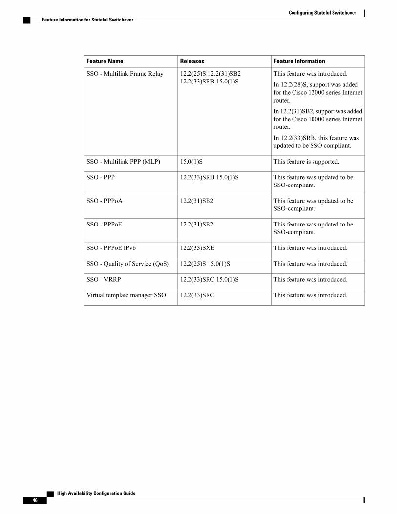
Feature InformationReleasesFeature Name
This feature was introduced.
In 12.2(28)S, support was addedfor the Cisco 12000 series Internetrouter.
In 12.2(31)SB2, support was addedfor the Cisco 10000 series Internetrouter.
In 12.2(33)SRB, this feature wasupdated to be SSO compliant.
12.2(25)S 12.2(31)SB212.2(33)SRB 15.0(1)S
SSO - Multilink Frame Relay
This feature is supported.15.0(1)SSSO - Multilink PPP (MLP)
This feature was updated to beSSO-compliant.
12.2(33)SRB 15.0(1)SSSO - PPP
This feature was updated to beSSO-compliant.
12.2(31)SB2SSO - PPPoA
This feature was updated to beSSO-compliant.
12.2(31)SB2SSO - PPPoE
This feature was introduced.12.2(33)SXESSO - PPPoE IPv6
This feature was introduced.12.2(25)S 15.0(1)SSSO - Quality of Service (QoS)
This feature was introduced.12.2(33)SRC 15.0(1)SSSO - VRRP
This feature was introduced.12.2(33)SRCVirtual template manager SSO
High Availability Configuration Guide46
Configuring Stateful SwitchoverFeature Information for Stateful Switchover
C H A P T E R 3Configuring Nonstop Forwarding
This module describes how to configure Nonstop Forwarding (NSF) in Cisco software to minimize theamount of time a network is unavailable to its users following a switchover. The main objective of NSF isto continue forwarding IP packets following a Route Processor (RP) switchover. NSF is supported by theBGP, EIGRP, IPv6, IS-IS, and OSPF protocols for routing and by CEF for forwarding.
The following terms are used throughout this document:
• NSF-aware device--A device that is running NSF-compatible software
• NSF-capable device--A device that is configured to support NSF. NSF-capable devices can rebuildrouting information from either NSF-aware or NSF-capable neighboring devices.
• Finding Feature Information, page 47
• Prerequisites for Nonstop Forwarding, page 48
• Restrictions for Nonstop Forwarding, page 48
• Information About Nonstop Forwarding, page 50
• How to Configure Nonstop Forwarding, page 57
• Configuration Examples for Nonstop Forwarding, page 68
• Additional References, page 72
• Feature Information for Nonstop Forwarding, page 74
Finding Feature InformationYour software release may not support all the features documented in this module. For the latest caveats andfeature information, see Bug Search Tool and the release notes for your platform and software release. Tofind information about the features documented in this module, and to see a list of the releases in which eachfeature is supported, see the feature information table.
Use Cisco Feature Navigator to find information about platform support and Cisco software image support.To access Cisco Feature Navigator, go to www.cisco.com/go/cfn. An account on Cisco.com is not required.
High Availability Configuration Guide 47
Prerequisites for Nonstop Forwarding• The networking device that is to be configured for NSFmust first be configured for SSO. For information,see the Configuring Stateful Switchover section.
• For Border Gateway Protocol (BGP) NSF, all neighboring devices must be NSF-aware and must beconfigured for BGP graceful restart.
• For Enhanced Interior Gateway Routing Protocol (EIGRP) NSF:
• All neighboring devices must be NSF-capable or NSF-aware.
• An NSF-aware device must be completely converged with the network before it can assist anNSF-capable device in an NSF restart operation.
• For Internet Engineering Task Force (IETF) Intermediate System to Intermediate System (IS-IS), allneighboring devices must be NSF-aware.
• For Open Shortest Path First (OSPF) NSF, all networking devices on the same network segment mustbe NSF-aware.
• For IPv6 NSF, IPv6 must be enabled on your networking device.
• On platforms supporting the Route Switch Processor (RSP), and where the Cisco Express Forwarding(CEF) switching mode is configurable, configure distributed CEF (dCEF) switching mode using the ipcef distributed command.
Restrictions for Nonstop Forwarding
General RestrictionsNSF capability is not enabled by default for OSPF, ISIS, or BGP. NSF capability is enabled by default forEIGRP only.
BGP NSF Restrictions• BGP support in NSF requires that neighbor networking devices be NSF-aware. If an NSF-capable devicediscovers that a particular BGP neighbor does not have graceful restart capability, it will not establishan NSF-capable session with that neighbor. All other neighbors that have graceful restart capability willcontinue to have NSF-capable sessions with this NSF-capable networking device.
• All devices must be configured with the same type of NSF helper mode, either IETF graceful restart orCisco NSF.
High Availability Configuration Guide48
Configuring Nonstop ForwardingPrerequisites for Nonstop Forwarding
EIGRP NSF Restrictions• An NSF-aware device cannot support two NSF-capable peers performing an NSF restart operation atthe same time. However, both neighbors will reestablish peering sessions after the NSF restart operationis complete.
• Distributed platforms that run a supporting version of Cisco software can support full NSF capabilities.These devices can perform a restart operation and can support other NSF capable peers.
• Single processor platforms that run a supporting version of Cisco software support only NSF awareness.These devices maintain adjacency and hold known routes for the NSF-capable neighbor until it signalsthat it is ready for the NSF-aware device to send its topology table or the route-hold timer expires.
OSPF NSF Restrictions• OSPF NSF for virtual links is not supported.
• OSPF NSF for sham links is not supported.
• OSPF NSF supports NSF/SSO for IPv4 traffic only.
• OSPFv3 is not supported with NSF/SSO. Only OSPFv2 is supported with NSF/SSO.
• All neighbor networking devices must be NSF-aware. If an NSF-capable device discovers that it hasnon-NSF-aware neighbors on a particular network segment, it will disable NSF capabilities for thatsegment. Other network segments composed entirely of NSF-capable or NSF-aware devices will continueto provide NSF capabilities.
• You can configure strict link state advertisement (LSA) checking on both NSF-aware and NSF-capabledevices; however, it is effective only when the device is in helper mode.
Cisco7200SeriesRouterRestrictions• The Cisco 7200 series router has a single CPU and cannot support the stateful switchover in the eventof a network processor engine (NPE) fault.
• The Cisco 7206 supports NSF and can operate in a peer role with a Cisco 7500, 10000, or 12000 seriesrouter running Cisco IOS Release 12.0(23)S or a later release. With NSF enabled, an RP switchover onthe Cisco 7500, 10000, or 12000 series router peer should not cause a loss of PPP, ATM, high-level datalink control (HDLC), or Frame Relay sessions, or a loss of any OSPF, BGP, or IS-IS adjacenciesestablished between the Cisco 7200 and the peer.
High Availability Configuration Guide 49
Configuring Nonstop ForwardingEIGRP NSF Restrictions
Information About Nonstop Forwarding
Nonstop Forwarding
In the following content, the term Route Processor (RP) is used to describe the route processing engineon all networking devices, regardless of the platform designation, unless otherwise noted.
Note
NSF works with the SSO feature in Cisco software to minimize the amount of time a network is unavailableto its users following a switchover. The main objective of NSF is to continue forwarding IP packets followingan RP switchover.
Usually, when a networking device restarts, all routing peers of that device detect that the device went downand then came back up. This transition results in what is called a routing flap, which could spread acrossmultiple routing domains. Routing flaps caused by routing restarts create routing instabilities, which aredetrimental to the overall network performance. NSF helps to suppress routing flaps in SSO-enabled devices,thus reducing network instability.
NSF allows for the forwarding of data packets to continue along known routes while the routing protocolinformation is being restored following a switchover. With NSF, peer networking devices do not experiencerouting flaps. Data traffic is forwarded through intelligent line cards or dual forwarding processors (FPs) whilethe standby RP assumes control from the failed active RP during a switchover. The ability of line cards andFPs to remain up through a switchover and to be kept current with the Forwarding Information Base (FIB)on the active RP is key to NSF operation.
The NSF feature provides the following benefits:
• Improved network availability—NSF continues forwarding network traffic and application stateinformation so that user session information is maintained after a switchover.
• Overall network stability—Network stability may be improved with the reduction in the number of routeflaps that had been created when devices in the network failed and lost their routing tables.
• Neighboring devices do not detect link flapping—Because the interfaces remain up across a switchover,neighboring devices do not detect a link flap (that is, the link does not go down and come back up).
• Prevention of routing flaps—Because SSO continues forwarding network traffic in the event of aswitchover, routing flaps are avoided.
• No loss of user sessions—User sessions established prior to the switchover are maintained.
NSF always runs together with SSO. SSO supported protocols and applications must be high-availability(HA)-aware. A feature or protocol is HA-aware if it maintains, either partially or completely, undisturbedoperation during an RP switchover. For some HA-aware protocols and applications, state information issynchronized from the active to the standby processor.
Cisco NSF Routing and ForwardingCisco NSF is supported by the BGP, EIGRP, IPv6, IS-IS, and OSPF protocols for routing and by CEF forforwarding. Of the routing protocols, BGP, EIGRP, IPv6, IS-IS, and OSPF have been enhanced with
High Availability Configuration Guide50
Configuring Nonstop ForwardingInformation About Nonstop Forwarding
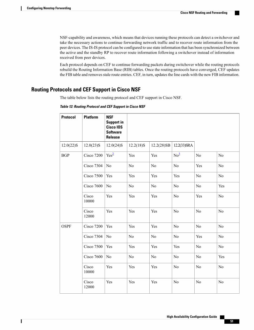
NSF-capability and awareness, which means that devices running these protocols can detect a switchover andtake the necessary actions to continue forwarding network traffic and to recover route information from thepeer devices. The IS-IS protocol can be configured to use state information that has been synchronized betweenthe active and the standby RP to recover route information following a switchover instead of informationreceived from peer devices.
Each protocol depends on CEF to continue forwarding packets during switchover while the routing protocolsrebuild the Routing Information Base (RIB) tables. Once the routing protocols have converged, CEF updatesthe FIB table and removes stale route entries. CEF, in turn, updates the line cards with the new FIB information.
Routing Protocols and CEF Support in Cisco NSFThe table below lists the routing protocol and CEF support in Cisco NSF.
Table 12: Routing Protocol and CEF Support in Cisco NSF
NSFSupport inCisco IOSSoftwareRelease
Protocol Platform
12.2(33)SRA12.2(28)SB12.2(18)S12.0(24)S12.0(23)S12.0(22)S
NoNoNo3YesYesYes2Cisco 7200BGP
NoYesNoNoNoNoCisco 7304
NoNoYesYesYesYesCisco 7500
YesNoNoNoNoNoCisco 7600
NoYesNoYesYesYesCisco10000
NoNoNoYesYesYesCisco12000
NoNoNoYesYesYesCisco 7200OSPF
NoYesNoNoNoNoCisco 7304
NoNoYesYesYesYesCisco 7500
YesNoNoNoNoNoCisco 7600
NoNoNoYesYesYesCisco10000
NoNoNoYesYesYesCisco12000
High Availability Configuration Guide 51
Configuring Nonstop ForwardingCisco NSF Routing and Forwarding
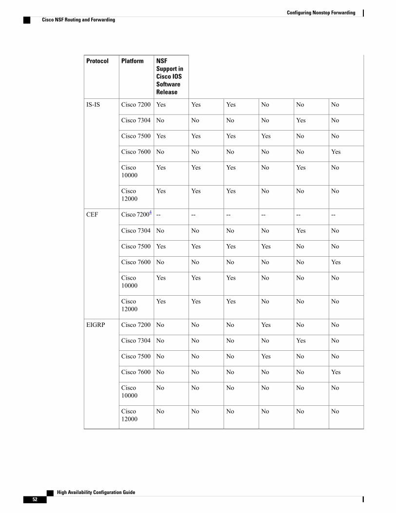
NSFSupport inCisco IOSSoftwareRelease
Protocol Platform
NoNoNoYesYesYesCisco 7200IS-IS
NoYesNoNoNoNoCisco 7304
NoNoYesYesYesYesCisco 7500
YesNoNoNoNoNoCisco 7600
NoYesNoYesYesYesCisco10000
NoNoNoYesYesYesCisco12000
------------Cisco 72004CEF
NoYesNoNoNoNoCisco 7304
NoNoYesYesYesYesCisco 7500
YesNoNoNoNoNoCisco 7600
NoNoNoYesYesYesCisco10000
NoNoNoYesYesYesCisco12000
NoNoYesNoNoNoCisco 7200EIGRP
NoYesNoNoNoNoCisco 7304
NoNoYesNoNoNoCisco 7500
YesNoNoNoNoNoCisco 7600
NoNoNoNoNoNoCisco10000
NoNoNoNoNoNoCisco12000
High Availability Configuration Guide52
Configuring Nonstop ForwardingCisco NSF Routing and Forwarding
2 The Cisco 7200 is a single-route processor system and cannot maintain its forwarding table in the event of a route processor failure. It cannot perform nonstopforwarding of packets. However, it supports the NSF protocol extensions for BGP, EIGRP, OSPF, and IS-IS. Therefore, it can peer with NSF-capable routersand facilitate the resynchronization of routing information with such routers.
3 The Cisco 7200 is NSF-aware in Cisco IOS Release 12.2(18)S.4 The Cisco 7200 is a single-processor device and does not support SSO; therefore, CEF support for NSF does not apply.
Cisco Express Forwarding and NSFA key element of NSF is packet forwarding. In a Cisco networking device, packet forwarding is provided byCEF. CEF maintains the FIB, and uses the FIB information that was current at the time of the switchover tocontinue forwarding packets during a switchover. This feature reduces traffic interruption during the switchover.
During normal NSF operation, CEF on the active RP synchronizes its current FIB and adjacency databaseswith the FIB and adjacency databases on the standby RP. Upon switchover of the active RP, the standby RPinitially has FIB and adjacency databases that are mirror images of those that were current on the active RP.For platforms with intelligent line cards, the line cards will maintain the current forwarding information overa switchover; for platforms with forwarding engines, CEF will keep the forwarding engine on the standby RPcurrent with changes that are sent to it by CEF on the active RP. In this way, the line cards or forwardingengines will be able to continue forwarding after a switchover as soon as the interfaces and a data path areavailable.
As the routing protocols start to repopulate the RIB on a prefix-by-prefix basis, the updates in turn causeprefix-by-prefix updates to CEF, which it uses to update the FIB and adjacency databases. Existing and newentries will receive the new version (“epoch”) number, indicating that they have been refreshed. The forwardinginformation is updated on the line cards or forwarding engine during convergence. The RP signals when theRIB has converged. The software removes all FIB and adjacency entries that have an epoch older than thecurrent switchover epoch. The FIB now represents the newest routing protocol forwarding information.
The routing protocols run only on the active RP, and they receive routing updates from their neighbor devices.Routing protocols do not run on the standby RP. Following a switchover, the routing protocols request thatthe NSF-aware neighbor devices send state information to help rebuild the routing tables. Alternately, theIS-IS protocol can be configured to synchronize state information from the active to the standby RP to helprebuild the routing table on the NSF-capable device in environments where neighbor devices are not NSF-aware.
For NSF operation, the routing protocols depend on CEF to continue forwarding packets while the routingprotocols rebuild the routing information. The CEF NSF feature operates by default while the networkingdevice is running in SSO mode. No configuration is necessary.
BGP NSF OperationsWhen a NSF-capable device begins a BGP session with a BGP peer, it sends an OPEN message to the peer.Included in the message is a declaration that the NSF-capable device has “graceful restart capability.”Gracefulrestart is the mechanism by which BGP routing peers avoid a routing flap following a switchover. If the BGPpeer has received this capability, it is aware that the device sending the message is NSF-capable. Both theNSF-capable device and its BGP peers need to exchange the graceful restart capability in their OPENmessages,at the time of session establishment. If both the peers do not exchange the graceful restart capability, thesession will not be graceful restart capable.
If the BGP session is lost during the RP switchover, the NSF-aware BGP peer marks all the routes associatedwith the NSF-capable device as stale; however, it continues to use these routes to make forwarding decisionsfor a set period of time. This functionality means that no packets are lost while the newly active RP is waitingfor convergence of the routing information with the BGP peers.
High Availability Configuration Guide 53
Configuring Nonstop ForwardingCisco Express Forwarding and NSF
After an RP switchover occurs, the NSF-capable device reestablishes the session with the BGP peer. Inestablishing the new session, it sends a new graceful restart message that identifies the NSF-capable deviceas having restarted.
At this point, the routing information is exchanged between the two BGP peers. Once this exchange is complete,the NSF-capable device uses the routing information to update the RIB and the FIB with the new forwardinginformation. The NSF-aware device uses the network information to remove stale routes from its BGP table.Following that, the BGP protocol is fully converged.
If a BGP peer does not support the graceful restart capability, it will ignore the graceful-restart capability inan OPEN message but will establish a BGP session with the NSF-capable device. This function will allowinteroperability with non-NSF-aware BGP peers (and without NSF functionality), but the BGP session withnon-NSF-aware BGP peers will not be graceful restart-capable.
BGP support in NSF requires that neighbor networking devices be NSF-aware; that is, the devices must havethe graceful restart capability and advertise that capability in their OPENmessage during session establishment.If an NSF-capable device discovers that a particular BGP neighbor does not have graceful restart capability,it will not establish an NSF-capable session with that neighbor. All other neighbors that have graceful restartcapability will continue to have NSF-capable sessions with this NSF-capable networking device.
EIGRP NSF OperationsCisco NSF is supported by the EIGRP protocol for routing and by CEF for forwarding. EIGRP depends onCEF to continue forwarding packets during switchover while the routing protocols rebuild the RoutingInformation Base (RIB) tables. Once the routing protocols have converged, CEF updates the FIB table andremoves stale route entries. CEF, in turn, updates the line cards with the new FIB information.
EIGRP nonstop forwarding (NSF) capabilities are exchanged by EIGRP peers in hello packets. TheNSF-capabledevice notifies its neighbors that an NSF restart operation has started by setting the restart (RS) bit in a hellopacket. When an NSF-aware device receives notification from an NSF-capable neighbor that an NSF-restartoperation is in progress, the NSF-capable and NSF-aware devices immediately exchange their topology tables.The NSF-aware device sends an end-of-table (EOT) update packet when the transmission of its topology tableis complete. The NSF-aware device then performs the following actions to assist the NSF-capable device:
• The EIGRP hello hold timer is expired to reduce the time interval set for hello packet generation andtransmission. This allows the NSF-aware device to reply to the NSF-capable device more quicklyreducing the amount of time required for the NSF-capable device to rediscover neighbors and rebuildthe topology table.
• The route-hold timer is started. This timer is used to set the period of time that the NSF-aware devicewill hold known routes for the NSF-capable neighbor.
• The NSF-aware device notes in the peer list that the NSF-capable neighbor is restarting, maintainsadjacency, and holds known routes for the NSF-capable neighbor until the neighbor signals that it isready for the NSF-aware device to send its topology table or the route-hold timer expires. If the route-holdtimer expires on the NSF-aware device, the NSF-aware device will discard held routes and treat theNSF-capable device as a new device joining the network and reestablishing adjacency accordingly.
• The NSF-aware device will continue to send queries to the NSF-capable device that is still convergingafter switchover, effectively extending the time before a stuck-in-active (SIA) condition can occur.
When the switchover operation is complete, the NSF-capable device notifies its neighbors that it has reconvergedand has received all of their topology tables by sending an EOT update packet to the assisting devices. TheNSF-capable device then returns to normal operation. The NSF-aware device will look for alternate paths (go
High Availability Configuration Guide54
Configuring Nonstop ForwardingEIGRP NSF Operations
active) for any routes that are not refreshed by the NSF-capable (restarting device). The NSF-aware devicewill then return to normal operation. If all paths are refreshed by the NSF-capable device, the NSF-awaredevice will immediately return to normal operation.
NSF-aware devices are completely compatible with non-NSF-aware or non-NSF-capable neighbors in anEIGRP network. A non-NSF-aware neighbor will ignore NSF capabilities and reset adjacencies and otherwisemaintain the peering sessions normally.
IPv6 support for NSF Operations
Nonstop Forwarding and Graceful Restart for MP-BGP IPv6 Address FamilyThe graceful restart capability is supported for IPv6 BGP unicast, multicast, and VPNv6 address families,enabling Cisco NSF functionality for BGP IPv6. The BGP graceful restart capability allows the BGP routingtable to be recovered from peers without keeping the TCP state.
NSF continues forwarding packets while routing protocols converge, therefore avoiding a route flap onswitchover. Forwarding is maintained by synchronizing the FIB between the active and standby RP. Onswitchover, forwarding is maintained using the FIB. The RIB is not kept synchronized; therefore, the RIB isempty on switchover. The RIB is repopulated by the routing protocols and subsequently informs the FIBabout RIB convergence by using the NSF_RIB_CONVERGED registry call. The FIB tables are updated fromthe RIB, removing any stale entries. The RIB starts a fail-safe timer during RP switchover, in case the routingprotocols fail to notify the RIB of convergence.
The Cisco BGP address family identifier (AFI) model is modular and scalable, and supports multiple AFIsand subsequent address family identifier (SAFI) configurations.
Nonstop Forwarding for IPv6 RIPRIP registers as an IPv6 NSF client. Doing so has the benefit of using RIP routes installed in the Cisco ExpressForwarding table until RIP has converged on the standby.
Nonstop Forwarding for Static RoutesCisco NSF supports IPv6 static routes.
IS-IS NSF OperationsWhen an IS-IS NSF-capable device performs an RP switchover, it must perform two tasks in order toresynchronize its Link State Database with its IS-IS neighbors. First, it must relearn the available IS-ISneighbors on the network without causing a reset of the neighbor relationship. Second, it must reacquire thecontents of the Link State Database for the network.
The IS-IS NSF feature offers two options when configuring NSF:
• IETF IS-IS
• Cisco IS-IS
High Availability Configuration Guide 55
Configuring Nonstop ForwardingIPv6 support for NSF Operations
If neighbor devices on a network segment are NSF-aware, meaning that neighbor devices are running asoftware version that supports the IETF Internet draft for device restartability, they will assist an IETF NSFdevice that is restarting. With IETF, neighbor devices provide adjacency and link-state information to helprebuild the routing information following a switchover. A benefit of IETF IS-IS configuration is operationbetween peer devices based on a proposed standard.
If you configure IETF on the networking device, but neighbor devices are not IETF-compatible, NSF willabort following a switchover.
If the neighbor devices on a network segment are not NSF-aware, you must use the Cisco configuration option.The Cisco IS-IS configuration transfers both protocol adjacency and link-state information from the active tothe standby RP. A benefit of Cisco configuration is that it does not rely on NSF-aware neighbors.
IETF IS-IS ConfigurationWith the IETF IS-IS configuration, the NSF-capable device sends IS-IS NSF restart requests to neighboringNSF-aware devices as quickly as possible after an RP switchover. Neighbor networking devices recognizethis restart request as a cue that the neighbor relationship with this device should not be reset, but that theyshould initiate database resynchronization with the restarting device. As the restarting device receives restartrequest responses from devices on the network, it can begin to rebuild its neighbor list.
Once this exchange is complete, the NSF-capable device uses the link-state information to remove stale routes,update the RIB, and update the FIB with the new forwarding information. IS-IS is then fully converged.
The switchover from one RP to the other happens within seconds. IS-IS reestablishes its routing table andresynchronizes with the network within a few additional seconds. At this point, IS-IS waits for a specifiedinterval before it will attempt a second NSF restart. During this time, the new standby RP will boot up andsynchronize its configuration with the active RP. The IS-IS NSF operation waits for a specified interval toensure that connections are stable before attempting another restart of IS-IS NSF. This functionality preventsIS-IS from attempting back-to-back NSF restarts with stale information.
Cisco IS-IS ConfigurationWith the Cisco configuration option, full adjacency and link-state packet (LSP) information is saved, or“checkpointed,” to the standby RP. Following a switchover, the newly active RP maintains its adjacenciesusing the checkpointed data, and can quickly rebuild its routing tables.
The switchover from one RP to the other happens within seconds. IS-IS reestablishes its routing table andresynchronizes with the network within a few additional seconds. At this point, IS-IS waits for a specifiedinterval before it will attempt a second NSF restart. During this time, the new standby RP will boot up andsynchronize its configuration with the active RP. Once this synchronization is completed, IS-IS adjacencyand LSP data is checkpointed to the standby RP; however, a new NSF restart will not be attempted by IS-ISuntil the interval time expires. This functionality prevents IS-IS from attempting back-to-back NSF restarts.IS-IS NSF provides a command to extend the wait time for interfaces that, for whatever reason, do not comeup in a timely fashion.
Following a switchover, Cisco IS-IS NSF has complete neighbor adjacency and LSP information; however,it must wait for all interfaces that had adjacencies prior to the switchover to come up. If an interface does notcome up within the allocated interface wait time, the routes learned from these neighbor devices are notconsidered in routing table recalculation.
High Availability Configuration Guide56
Configuring Nonstop ForwardingIS-IS NSF Operations
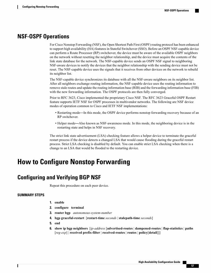
NSF-OSPF OperationsFor Cisco Nonstop Forwarding (NSF), the Open Shortest Path First (OSPF) routing protocol has been enhancedto support high availability (HA) features in Stateful Switchover (SSO). Before an OSPF NSF-capable devicecan perform a Route Processor (RP) switchover, the device must be aware of the available OSPF neighborson the network without resetting the neighbor relationship, and the device must acquire the contents of thelink state database for the network. The NSF-capable device sends an OSPF NSF signal to neighboringNSF-aware devices to notify the devices that the neighbor relationship with the sending device must not bereset. The NSF-capable device uses the signals that it receives from other devices on the network to rebuildits neighbor list.
The NSF-capable device synchronizes its database with all the NSF-aware neighbors on its neighbor list.After all neighbors exchange routing information, the NSF-capable device uses the routing information toremove stale routes and update the routing information base (RIB) and the forwarding information base (FIB)with the new forwarding information. The OSPF protocols are then fully converged.
Prior to RFC 3623, Cisco implemented the proprietary Cisco NSF. The RFC 3623 Graceful OSPF Restartfeature supports IETF NSF for OSPF processes in multivendor networks. The following are NSF devicemodes of operation common to Cisco and IETF NSF implementations:
• Restarting mode—In this mode, the OSPF device performs nonstop forwarding recovery because of anRP switchover.
• Helper mode—Also known as NSF-awareness mode. In this mode, the neighboring device is in therestarting state and helps in NSF recovery.
The strict link state advertisement (LSA) checking feature allows a helper device to terminate the gracefulrestart process if the device detects a changed LSA that would cause flooding during the graceful restartprocess. Strict LSA checking is disabled by default. You can enable strict LSA checking when there is achange to an LSA that would be flooded to the restarting device.
How to Configure Nonstop Forwarding
Configuring and Verifying BGP NSFRepeat this procedure on each peer device.
SUMMARY STEPS
1. enable2. configure terminal3. router bgp autonomous-system-number4. bgp graceful-restart [restart-time seconds | stalepath-time seconds]5. end6. show ip bgp neighbors [ip-address [advertised-routes | dampened-routes | flap-statistics | paths
[reg-exp] | received prefix-filter | received-routes | routes | policy[detail]]]
High Availability Configuration Guide 57
Configuring Nonstop ForwardingNSF-OSPF Operations
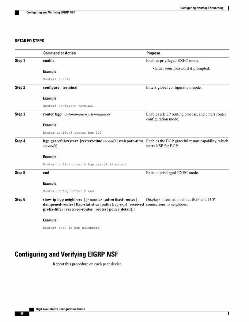
DETAILED STEPS
PurposeCommand or Action
Enables privileged EXEC mode.enableStep 1
Example:
Router> enable
• Enter your password if prompted.
Enters global configuration mode.configure terminal
Example:
Router# configure terminal
Step 2
Enables a BGP routing process, and enters routerconfiguration mode.
router bgp autonomous-system-number
Example:
Router(config)# router bgp 120
Step 3
Enables the BGP graceful restart capability, whichstarts NSF for BGP.
bgp graceful-restart [restart-time seconds | stalepath-timeseconds]
Example:
Router(config-router)# bgp graceful-restart
Step 4
Exits to privileged EXEC mode.end
Example:
Router(config-router)# end
Step 5
Displays information about BGP and TCPconnections to neighbors.
show ip bgp neighbors [ip-address [advertised-routes |dampened-routes | flap-statistics | paths [reg-exp] | receivedprefix-filter | received-routes | routes | policy[detail]]]
Step 6
Example:
Router# show ip bgp neighbors
Configuring and Verifying EIGRP NSFRepeat this procedure on each peer device.
High Availability Configuration Guide58
Configuring Nonstop ForwardingConfiguring and Verifying EIGRP NSF
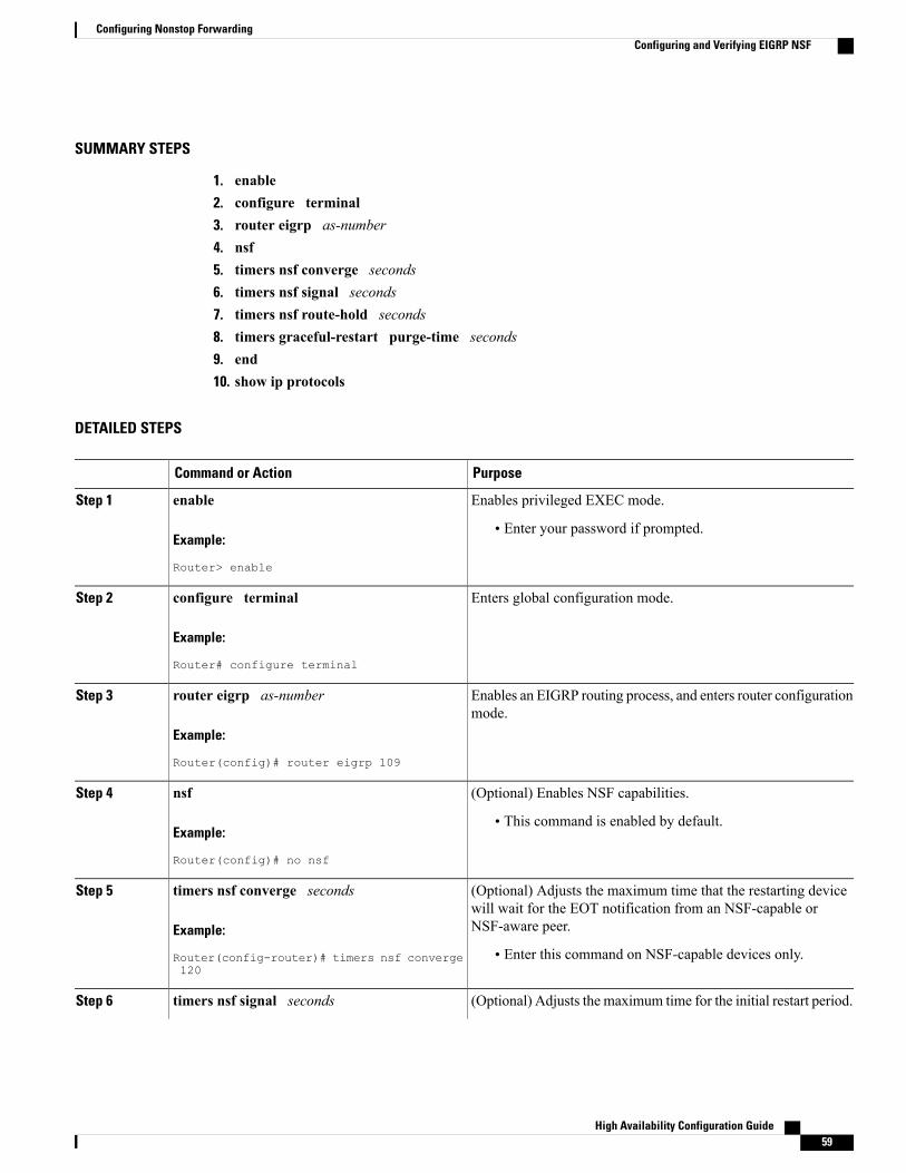
SUMMARY STEPS
1. enable2. configure terminal3. router eigrp as-number4. nsf5. timers nsf converge seconds6. timers nsf signal seconds7. timers nsf route-hold seconds8. timers graceful-restart purge-time seconds9. end10. show ip protocols
DETAILED STEPS
PurposeCommand or Action
Enables privileged EXEC mode.enableStep 1
Example:
Router> enable
• Enter your password if prompted.
Enters global configuration mode.configure terminal
Example:
Router# configure terminal
Step 2
Enables an EIGRP routing process, and enters router configurationmode.
router eigrp as-number
Example:
Router(config)# router eigrp 109
Step 3
(Optional) Enables NSF capabilities.nsfStep 4
Example:
Router(config)# no nsf
• This command is enabled by default.
(Optional) Adjusts the maximum time that the restarting devicewill wait for the EOT notification from an NSF-capable orNSF-aware peer.
timers nsf converge seconds
Example:
Router(config-router)# timers nsf converge120
Step 5
• Enter this command on NSF-capable devices only.
(Optional) Adjusts the maximum time for the initial restart period.timers nsf signal secondsStep 6
High Availability Configuration Guide 59
Configuring Nonstop ForwardingConfiguring and Verifying EIGRP NSF
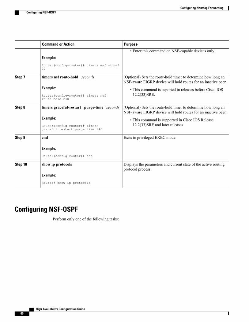
PurposeCommand or Action
Example:
Router(config-router)# timers nsf signal20
• Enter this command on NSF-capable devices only.
(Optional) Sets the route-hold timer to determine how long anNSF-aware EIGRP device will hold routes for an inactive peer.
timers nsf route-hold seconds
Example:
Router(config-router)# timers nsfroute-hold 240
Step 7
• This command is suported in releases before Cisco IOS12.2(33)SRE.
(Optional) Sets the route-hold timer to determine how long anNSF-aware EIGRP device will hold routes for an inactive peer.
timers graceful-restart purge-time seconds
Example:
Router(config-router)# timersgraceful-restart purge-time 240
Step 8
• This command is supported in Cisco IOS Release12.2(33)SRE and later releases.
Exits to privileged EXEC mode.end
Example:
Router(config-router)# end
Step 9
Displays the parameters and current state of the active routingprotocol process.
show ip protocols
Example:
Router# show ip protocols
Step 10
Configuring NSF-OSPFPerform only one of the following tasks:
High Availability Configuration Guide60
Configuring Nonstop ForwardingConfiguring NSF-OSPF
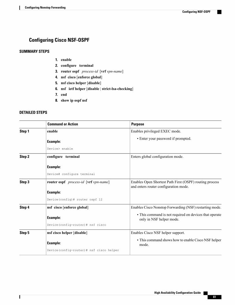
Configuring Cisco NSF-OSPF
SUMMARY STEPS
1. enable2. configure terminal3. router ospf process-id [vrf vpn-name]4. nsf cisco [enforce global]5. nsf cisco helper [disable]6. nsf ietf helper [disable | strict-lsa-checking]7. end8. show ip ospf nsf
DETAILED STEPS
PurposeCommand or Action
Enables privileged EXEC mode.enableStep 1
Example:
Device> enable
• Enter your password if prompted.
Enters global configuration mode.configure terminal
Example:
Device# configure terminal
Step 2
Enables Open Shortest Path First (OSPF) routing processand enters router configuration mode.
router ospf process-id [vrf vpn-name]
Example:
Device(config)# router ospf 12
Step 3
Enables Cisco Nonstop Forwarding (NSF) restarting mode.nsf cisco [enforce global]Step 4
Example:
Device(config-router)# nsf cisco
• This command is not required on devices that operateonly in NSF helper mode.
Enables Cisco NSF helper support.nsf cisco helper [disable]Step 5
Example:
Device(config-router)# nsf cisco helper
• This command shows how to enable Cisco NSF helpermode.
High Availability Configuration Guide 61
Configuring Nonstop ForwardingConfiguring NSF-OSPF
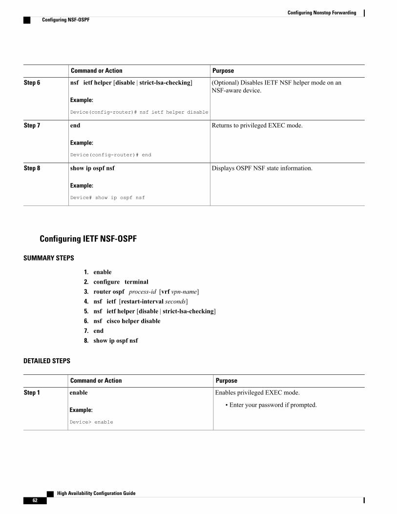
PurposeCommand or Action
(Optional) Disables IETF NSF helper mode on anNSF-aware device.
nsf ietf helper [disable | strict-lsa-checking]
Example:
Device(config-router)# nsf ietf helper disable
Step 6
Returns to privileged EXEC mode.end
Example:
Device(config-router)# end
Step 7
Displays OSPF NSF state information.show ip ospf nsf
Example:
Device# show ip ospf nsf
Step 8
Configuring IETF NSF-OSPF
SUMMARY STEPS
1. enable2. configure terminal3. router ospf process-id [vrf vpn-name]4. nsf ietf [restart-interval seconds]5. nsf ietf helper [disable | strict-lsa-checking]6. nsf cisco helper disable7. end8. show ip ospf nsf
DETAILED STEPS
PurposeCommand or Action
Enables privileged EXEC mode.enableStep 1
Example:
Device> enable
• Enter your password if prompted.
High Availability Configuration Guide62
Configuring Nonstop ForwardingConfiguring NSF-OSPF
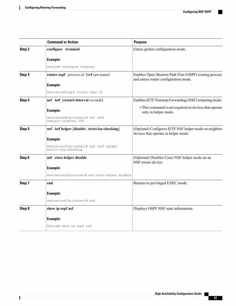
PurposeCommand or Action
Enters global configuration mode.configure terminal
Example:
Device# configure terminal
Step 2
Enables Open Shortest Path First (OSPF) routing processand enters router configuration mode.
router ospf process-id [vrf vpn-name]
Example:
Device(config)# router ospf 12
Step 3
Enables IETFNonstop Forwarding (NSF) restartingmode.nsf ietf [restart-interval seconds]Step 4
Example:
Device(config-router)# nsf ietfrestart-interval 180
• This command is not required on devices that operateonly in helper mode.
(Optional) Configures IETFNSF helper mode on neighbordevices that operate in helper mode.
nsf ietf helper [disable | strict-lsa-checking]
Example:
Device(config-router)# nsf ietf helperstrict-lsa-checking
Step 5
(Optional) Disables Cisco NSF helper mode on anNSF-aware device.
nsf cisco helper disable
Example:
Device(config-router)# nsf cisco helper disable
Step 6
Returns to privileged EXEC mode.end
Example:
Device(config-router)# end
Step 7
Displays OSPF NSF state information.show ip ospf nsf
Example:
Device# show ip ospf nsf
Step 8
High Availability Configuration Guide 63
Configuring Nonstop ForwardingConfiguring NSF-OSPF
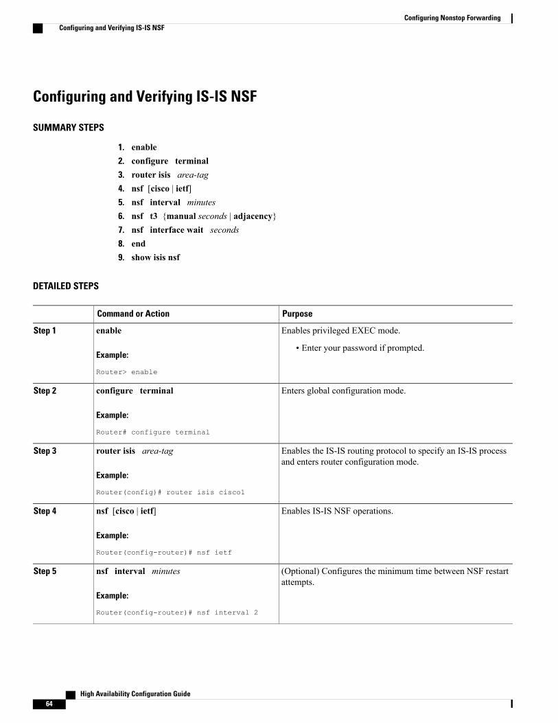
Configuring and Verifying IS-IS NSF
SUMMARY STEPS
1. enable2. configure terminal3. router isis area-tag4. nsf [cisco | ietf]5. nsf interval minutes6. nsf t3 {manual seconds | adjacency}7. nsf interface wait seconds8. end9. show isis nsf
DETAILED STEPS
PurposeCommand or Action
Enables privileged EXEC mode.enableStep 1
Example:
Router> enable
• Enter your password if prompted.
Enters global configuration mode.configure terminal
Example:
Router# configure terminal
Step 2
Enables the IS-IS routing protocol to specify an IS-IS processand enters router configuration mode.
router isis area-tag
Example:
Router(config)# router isis cisco1
Step 3
Enables IS-IS NSF operations.nsf [cisco | ietf]
Example:
Router(config-router)# nsf ietf
Step 4
(Optional) Configures the minimum time between NSF restartattempts.
nsf interval minutes
Example:
Router(config-router)# nsf interval 2
Step 5
High Availability Configuration Guide64
Configuring Nonstop ForwardingConfiguring and Verifying IS-IS NSF
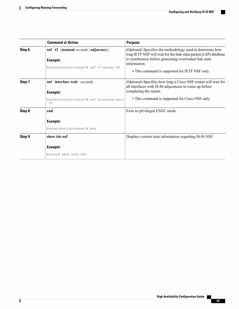
PurposeCommand or Action
(Optional) Specifies the methodology used to determine howlong IETFNSFwill wait for the link-state packet (LSP) database
nsf t3 {manual seconds | adjacency}
Example:
Router(config-router)# nsf t3 manual 40
Step 6
to synchronize before generating overloaded link-stateinformation.
• This command is supported for IETF NSF only.
(Optional) Specifies how long a Cisco NSF restart will wait forall interfaces with IS-IS adjacencies to come up beforecompleting the restart.
nsf interface wait seconds
Example:
Router(config-router)# nsf interface wait15
Step 7
• This command is supported for Cisco NSF only.
Exits to privileged EXEC mode.end
Example:
Router(config-router)# end
Step 8
Displays current state information regarding IS-IS NSF.show isis nsf
Example:
Router# show isis nsf
Step 9
High Availability Configuration Guide 65
Configuring Nonstop ForwardingConfiguring and Verifying IS-IS NSF
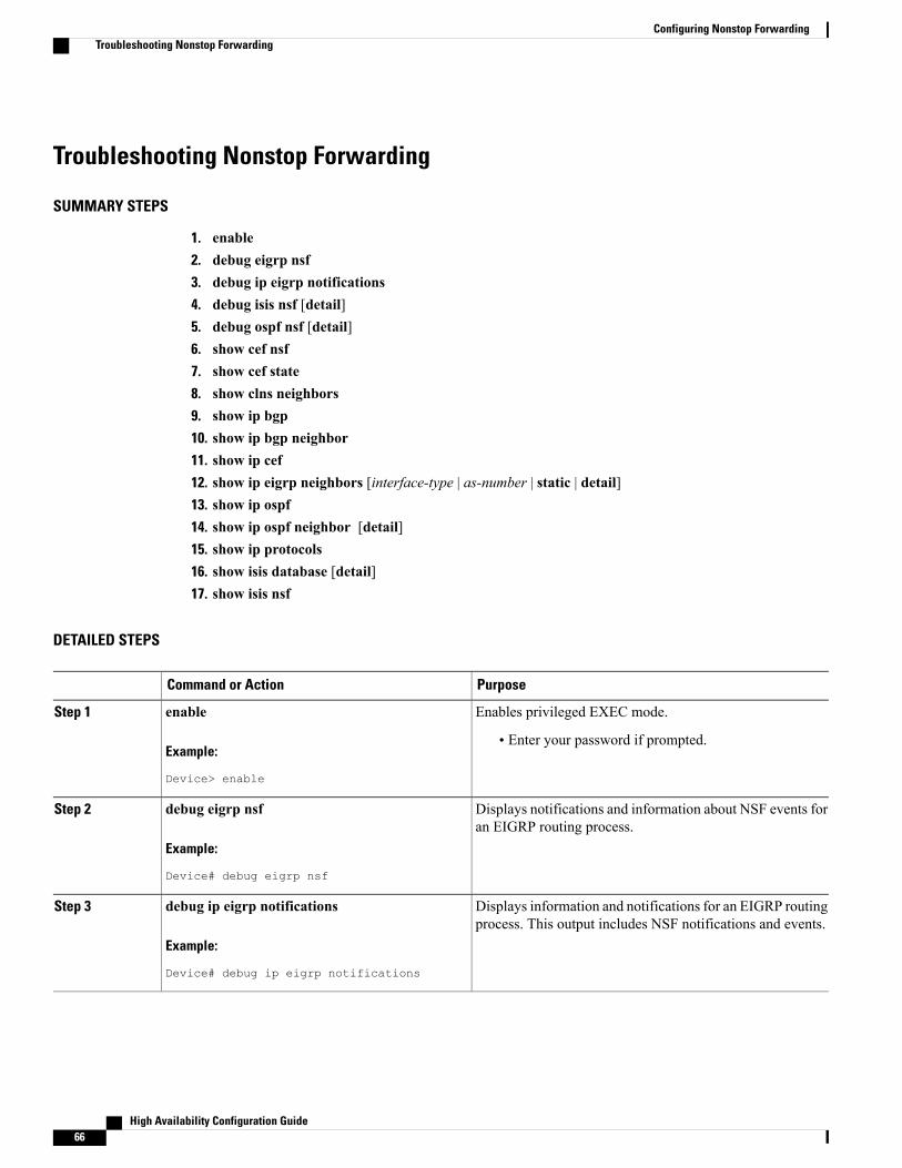
Troubleshooting Nonstop Forwarding
SUMMARY STEPS
1. enable2. debug eigrp nsf3. debug ip eigrp notifications4. debug isis nsf [detail]5. debug ospf nsf [detail]6. show cef nsf7. show cef state8. show clns neighbors9. show ip bgp10. show ip bgp neighbor11. show ip cef12. show ip eigrp neighbors [interface-type | as-number | static | detail]13. show ip ospf14. show ip ospf neighbor [detail]15. show ip protocols16. show isis database [detail]17. show isis nsf
DETAILED STEPS
PurposeCommand or Action
Enables privileged EXEC mode.enableStep 1
Example:
Device> enable
• Enter your password if prompted.
Displays notifications and information about NSF events foran EIGRP routing process.
debug eigrp nsf
Example:
Device# debug eigrp nsf
Step 2
Displays information and notifications for an EIGRP routingprocess. This output includes NSF notifications and events.
debug ip eigrp notifications
Example:
Device# debug ip eigrp notifications
Step 3
High Availability Configuration Guide66
Configuring Nonstop ForwardingTroubleshooting Nonstop Forwarding

PurposeCommand or Action
Displays information about the IS-IS state during a CiscoNSF restart.
debug isis nsf [detail]
Example:
Device# debug isis nsf [detail]
Step 4
Displays debugging messages related to OSPF Cisco NSFcommands.
debug ospf nsf [detail]
Example:
Device# debug ospf nsf [detail]
Step 5
Displays the current NSF state of CEF on both the active andstandby RPs.
show cef nsf
Example:
Device# show cef nsf
Step 6
Displays the CEF state on a networking device.show cef state
Example:
Device# show cef state
Step 7
Displays both end system and intermediate system neighbors.show clns neighbors
Example:
Device# show clns neighbors
Step 8
Displays entries in the BGP routing table.show ip bgp
Example:
Device# show ip bgp
Step 9
Displays information about the TCP and BGP connectionsto neighbor devices.
show ip bgp neighbor
Example:
Device# show ip bgp neighbor
Step 10
Displays entries in the FIB that are unresolved, or displaysFIB summary.
show ip cef
Example:
Device# show ip cef
Step 11
High Availability Configuration Guide 67
Configuring Nonstop ForwardingTroubleshooting Nonstop Forwarding
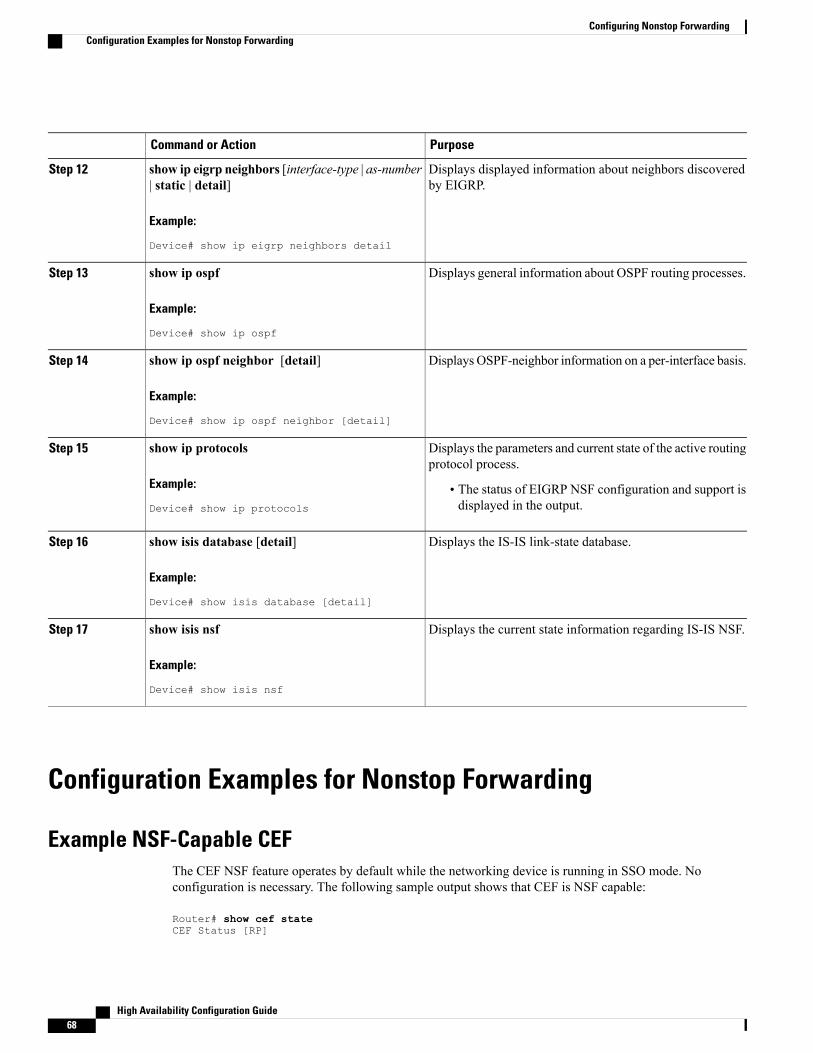
PurposeCommand or Action
Displays displayed information about neighbors discoveredby EIGRP.
show ip eigrp neighbors [interface-type | as-number| static | detail]
Example:
Device# show ip eigrp neighbors detail
Step 12
Displays general information about OSPF routing processes.show ip ospf
Example:
Device# show ip ospf
Step 13
Displays OSPF-neighbor information on a per-interface basis.show ip ospf neighbor [detail]
Example:
Device# show ip ospf neighbor [detail]
Step 14
Displays the parameters and current state of the active routingprotocol process.
show ip protocols
Example:
Device# show ip protocols
Step 15
• The status of EIGRP NSF configuration and support isdisplayed in the output.
Displays the IS-IS link-state database.show isis database [detail]
Example:
Device# show isis database [detail]
Step 16
Displays the current state information regarding IS-IS NSF.show isis nsf
Example:
Device# show isis nsf
Step 17
Configuration Examples for Nonstop Forwarding
Example NSF-Capable CEFThe CEF NSF feature operates by default while the networking device is running in SSO mode. Noconfiguration is necessary. The following sample output shows that CEF is NSF capable:
Router# show cef stateCEF Status [RP]
High Availability Configuration Guide68
Configuring Nonstop ForwardingConfiguration Examples for Nonstop Forwarding
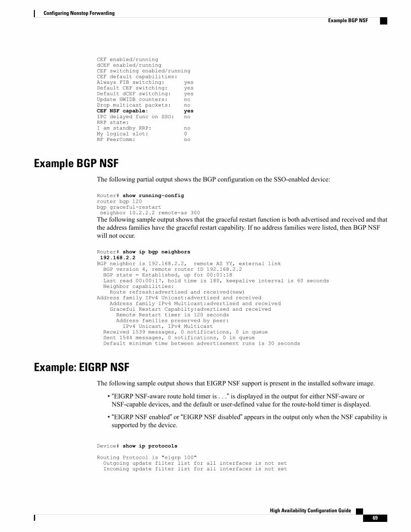
CEF enabled/runningdCEF enabled/runningCEF switching enabled/runningCEF default capabilities:Always FIB switching: yesDefault CEF switching: yesDefault dCEF switching: yesUpdate HWIDB counters: noDrop multicast packets: noCEF NSF capable: yesIPC delayed func on SSO: noRRP state:I am standby RRP: noMy logical slot: 0RF PeerComm: no
Example BGP NSFThe following partial output shows the BGP configuration on the SSO-enabled device:
Router# show running-configrouter bgp 120bgp graceful-restartneighbor 10.2.2.2 remote-as 300The following sample output shows that the graceful restart function is both advertised and received and thatthe address families have the graceful restart capability. If no address families were listed, then BGP NSFwill not occur.
Router# show ip bgp neighbors192.168.2.2BGP neighbor is 192.168.2.2, remote AS YY, external linkBGP version 4, remote router ID 192.168.2.2BGP state = Established, up for 00:01:18Last read 00:00:17, hold time is 180, keepalive interval is 60 secondsNeighbor capabilities:Route refresh:advertised and received(new)
Address family IPv4 Unicast:advertised and receivedAddress family IPv4 Multicast:advertised and receivedGraceful Restart Capabilty:advertised and receivedRemote Restart timer is 120 secondsAddress families preserved by peer:IPv4 Unicast, IPv4 Multicast
Received 1539 messages, 0 notifications, 0 in queueSent 1544 messages, 0 notifications, 0 in queueDefault minimum time between advertisement runs is 30 seconds
Example: EIGRP NSFThe following sample output shows that EIGRP NSF support is present in the installed software image.
• “EIGRP NSF-aware route hold timer is . . .” is displayed in the output for either NSF-aware orNSF-capable devices, and the default or user-defined value for the route-hold timer is displayed.
• “EIGRP NSF enabled” or “EIGRP NSF disabled” appears in the output only when the NSF capability issupported by the device.
Device# show ip protocols
Routing Protocol is "eigrp 100"Outgoing update filter list for all interfaces is not setIncoming update filter list for all interfaces is not set
High Availability Configuration Guide 69
Configuring Nonstop ForwardingExample BGP NSF
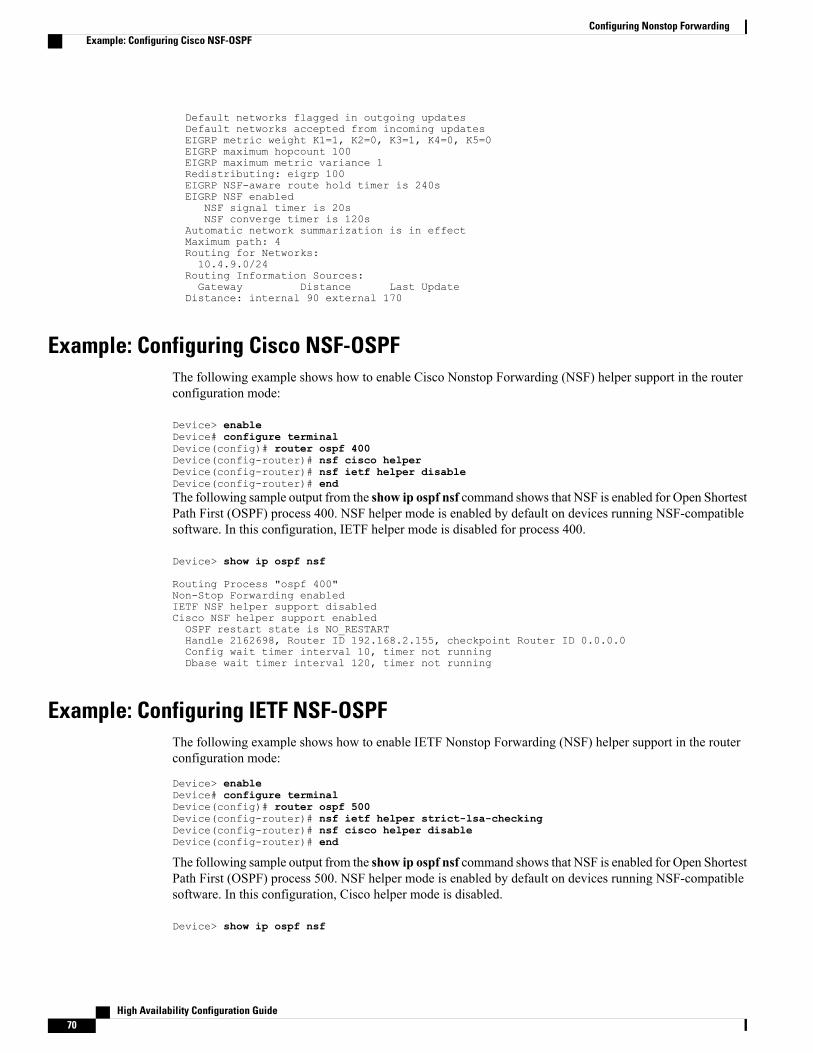
Default networks flagged in outgoing updatesDefault networks accepted from incoming updatesEIGRP metric weight K1=1, K2=0, K3=1, K4=0, K5=0EIGRP maximum hopcount 100EIGRP maximum metric variance 1Redistributing: eigrp 100EIGRP NSF-aware route hold timer is 240sEIGRP NSF enabled
NSF signal timer is 20sNSF converge timer is 120s
Automatic network summarization is in effectMaximum path: 4Routing for Networks:10.4.9.0/24
Routing Information Sources:Gateway Distance Last Update
Distance: internal 90 external 170
Example: Configuring Cisco NSF-OSPFThe following example shows how to enable Cisco Nonstop Forwarding (NSF) helper support in the routerconfiguration mode:
Device> enableDevice# configure terminalDevice(config)# router ospf 400Device(config-router)# nsf cisco helperDevice(config-router)# nsf ietf helper disableDevice(config-router)# endThe following sample output from the show ip ospf nsf command shows that NSF is enabled for Open ShortestPath First (OSPF) process 400. NSF helper mode is enabled by default on devices running NSF-compatiblesoftware. In this configuration, IETF helper mode is disabled for process 400.
Device> show ip ospf nsf
Routing Process "ospf 400"Non-Stop Forwarding enabledIETF NSF helper support disabledCisco NSF helper support enabledOSPF restart state is NO_RESTARTHandle 2162698, Router ID 192.168.2.155, checkpoint Router ID 0.0.0.0Config wait timer interval 10, timer not runningDbase wait timer interval 120, timer not running
Example: Configuring IETF NSF-OSPFThe following example shows how to enable IETF Nonstop Forwarding (NSF) helper support in the routerconfiguration mode:
Device> enableDevice# configure terminalDevice(config)# router ospf 500Device(config-router)# nsf ietf helper strict-lsa-checkingDevice(config-router)# nsf cisco helper disableDevice(config-router)# end
The following sample output from the show ip ospf nsf command shows that NSF is enabled for Open ShortestPath First (OSPF) process 500. NSF helper mode is enabled by default on devices running NSF-compatiblesoftware. In this configuration, Cisco helper mode is disabled.
Device> show ip ospf nsf
High Availability Configuration Guide70
Configuring Nonstop ForwardingExample: Configuring Cisco NSF-OSPF
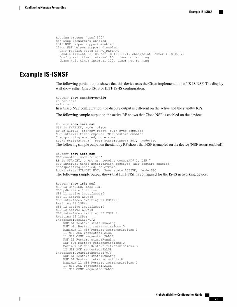
Routing Process "ospf 500"Non-Stop Forwarding enabledIETF NSF helper support enabledCisco NSF helper support disabledOSPF restart state is NO_RESTARTHandle 1786466333, Router ID 10.1.1.1, checkpoint Router ID 0.0.0.0Config wait timer interval 10, timer not runningDbase wait timer interval 120, timer not running
Example IS-ISNSFThe following partial output shows that this device uses the Cisco implementation of IS-IS NSF. The displaywill show either Cisco IS-IS or IETF IS-IS configuration.
Router# show running-configrouter isisnsf ciscoIn a Cisco NSF configuration, the display output is different on the active and the standby RPs.
The following sample output on the active RP shows that Cisco NSF is enabled on the device:
Router# show isis nsfNSF is ENABLED, mode 'cisco'RP is ACTIVE, standby ready, bulk sync completeNSF interval timer expired (NSF restart enabled)Checkpointing enabled, no errorsLocal state:ACTIVE, Peer state:STANDBY HOT, Mode:SSOThe following sample output on the standby RP shows that NSF is enabled on the device (NSF restart enabled):
Router# show isis nsfNSF enabled, mode 'cisco'RP is STANDBY, chkpt msg receive count:ADJ 2, LSP 7NSF interval timer notification received (NSF restart enabled)Checkpointing enabled, no errorsLocal state:STANDBY HOT, Peer state:ACTIVE, Mode:SSOThe following sample output shows that IETF NSF is configured for the IS-IS networking device:
Router# show isis nsfNSF is ENABLED, mode IETFNSF pdb state:InactiveNSF L1 active interfaces:0NSF L1 active LSPs:0NSF interfaces awaiting L1 CSNP:0Awaiting L1 LSPs:NSF L2 active interfaces:0NSF L2 active LSPs:0NSF interfaces awaiting L2 CSNP:0Awaiting L2 LSPs:Interface:Serial3/0/2
NSF L1 Restart state:RunningNSF p2p Restart retransmissions:0Maximum L1 NSF Restart retransmissions:3L1 NSF ACK requested:FALSEL1 NSF CSNP requested:FALSENSF L2 Restart state:RunningNSF p2p Restart retransmissions:0Maximum L2 NSF Restart retransmissions:3L2 NSF ACK requested:FALSE
Interface:GigabitEthernet2/0/0NSF L1 Restart state:RunningNSF L1 Restart retransmissions:0Maximum L1 NSF Restart retransmissions:3L1 NSF ACK requested:FALSEL1 NSF CSNP requested:FALSE
High Availability Configuration Guide 71
Configuring Nonstop ForwardingExample IS-ISNSF
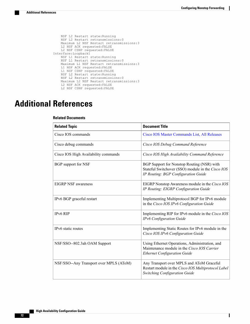
NSF L2 Restart state:RunningNSF L2 Restart retransmissions:0Maximum L2 NSF Restart retransmissions:3L2 NSF ACK requested:FALSEL2 NSF CSNP requested:FALSE
Interface:Loopback1NSF L1 Restart state:RunningNSF L1 Restart retransmissions:0Maximum L1 NSF Restart retransmissions:3L1 NSF ACK requested:FALSEL1 NSF CSNP requested:FALSENSF L2 Restart state:RunningNSF L2 Restart retransmissions:0Maximum L2 NSF Restart retransmissions:3L2 NSF ACK requested:FALSEL2 NSF CSNP requested:FALSE
Additional ReferencesRelated Documents
Document TitleRelated Topic
Cisco IOS Master Commands List, All ReleasesCisco IOS commands
Cisco IOS Debug Command ReferenceCisco debug commands
Cisco IOS High Availability Command ReferenceCisco IOS High Availability commands
BGP Support for Nonstop Routing (NSR) withStateful Switchover (SSO) module in the Cisco IOSIP Routing: BGP Configuration Guide
BGP support for NSF
EIGRP Nonstop Awareness module in the Cisco IOSIP Routing: EIGRP Configuration Guide
EIGRP NSF awareness
Implementing Multiprotocol BGP for IPv6 modulein the Cisco IOS IPv6 Configuration Guide
IPv6 BGP graceful restart
Implementing RIP for IPv6 module in the Cisco IOSIPv6 Configuration Guide
IPv6 RIP
Implementing Static Routes for IPv6 module in theCisco IOS IPv6 Configuration Guide
IPv6 static routes
Using Ethernet Operations, Administration, andMaintenance module in the Cisco IOS CarrierEthernet Configuration Guide
NSF/SSO--802.3ah OAM Support
Any Transport over MPLS and AToM GracefulRestart module in the Cisco IOSMultiprotocol LabelSwitching Configuration Guide
NSF/SSO--Any Transport over MPLS (AToM)
High Availability Configuration Guide72
Configuring Nonstop ForwardingAdditional References
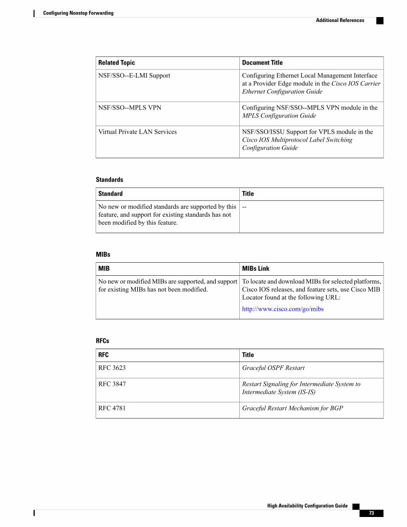
Document TitleRelated Topic
Configuring Ethernet Local Management Interfaceat a Provider Edge module in the Cisco IOS CarrierEthernet Configuration Guide
NSF/SSO--E-LMI Support
Configuring NSF/SSO--MPLS VPN module in theMPLS Configuration Guide
NSF/SSO--MPLS VPN
NSF/SSO/ISSU Support for VPLS module in theCisco IOS Multiprotocol Label SwitchingConfiguration Guide
Virtual Private LAN Services
Standards
TitleStandard
--No new or modified standards are supported by thisfeature, and support for existing standards has notbeen modified by this feature.
MIBs
MIBs LinkMIB
To locate and downloadMIBs for selected platforms,Cisco IOS releases, and feature sets, use Cisco MIBLocator found at the following URL:
http://www.cisco.com/go/mibs
No new or modifiedMIBs are supported, and supportfor existing MIBs has not been modified.
RFCs
TitleRFC
Graceful OSPF RestartRFC 3623
Restart Signaling for Intermediate System toIntermediate System (IS-IS)
RFC 3847
Graceful Restart Mechanism for BGPRFC 4781
High Availability Configuration Guide 73
Configuring Nonstop ForwardingAdditional References
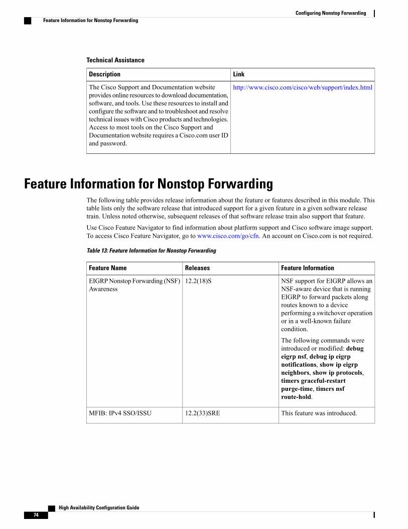
Technical Assistance
LinkDescription
http://www.cisco.com/cisco/web/support/index.htmlThe Cisco Support and Documentation websiteprovides online resources to download documentation,software, and tools. Use these resources to install andconfigure the software and to troubleshoot and resolvetechnical issues with Cisco products and technologies.Access to most tools on the Cisco Support andDocumentation website requires a Cisco.com user IDand password.
Feature Information for Nonstop ForwardingThe following table provides release information about the feature or features described in this module. Thistable lists only the software release that introduced support for a given feature in a given software releasetrain. Unless noted otherwise, subsequent releases of that software release train also support that feature.
Use Cisco Feature Navigator to find information about platform support and Cisco software image support.To access Cisco Feature Navigator, go to www.cisco.com/go/cfn. An account on Cisco.com is not required.
Table 13: Feature Information for Nonstop Forwarding
Feature InformationReleasesFeature Name
NSF support for EIGRP allows anNSF-aware device that is runningEIGRP to forward packets alongroutes known to a deviceperforming a switchover operationor in a well-known failurecondition.
The following commands wereintroduced or modified: debugeigrp nsf, debug ip eigrpnotifications, show ip eigrpneighbors, show ip protocols,timers graceful-restartpurge-time, timers nsfroute-hold.
12.2(18)SEIGRPNonstop Forwarding (NSF)Awareness
This feature was introduced.12.2(33)SREMFIB: IPv4 SSO/ISSU
High Availability Configuration Guide74
Configuring Nonstop ForwardingFeature Information for Nonstop Forwarding
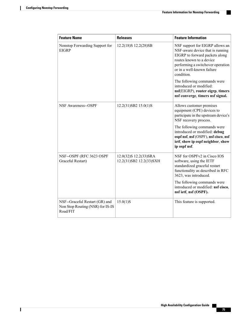
Feature InformationReleasesFeature Name
NSF support for EIGRP allows anNSF-aware device that is runningEIGRP to forward packets alongroutes known to a deviceperforming a switchover operationor in a well-known failurecondition.
The following commands wereintroduced or modified:nsf(EIGRP), router eigrp, timersnsf converge, timers nsf signal.
12.2(18)S 12.2(28)SBNonstop Forwarding Support forEIGRP
Allows customer premisesequipment (CPE) devices toparticipate in the upstream device’sNSF recovery process.
The following commands wereintroduced or modified: debugospf nsf, nsf (OSPF), nsf cisco, nsfietf, show ip ospf neighbor, showip ospf nsf.
12.2(31)SB2 15.0(1)SNSF Awareness--OSPF
NSF for OSPFv2 in Cisco IOSsoftware, using the IETFstandardized graceful restartfunctionality as described in RFC3623, was introduced.
The following commands wereintroduced or modified: nsf cisco,nsf ietf, nsf (OSPF).
12.0(32)S 12.2(33)SRA12.2(31)SB2 12.2(33)SXH
NSF--OSPF (RFC 3623 OSPFGraceful Restart)
This feature is supported.15.0(1)SNSF--Graceful Restart (GR) andNon Stop Routing (NSR) for IS-ISRoad/FIT
High Availability Configuration Guide 75
Configuring Nonstop ForwardingFeature Information for Nonstop Forwarding

Feature InformationReleasesFeature Name
12.0(22)S 12.0(23)S 12.0(24)S12.2(20)S 15.0(1)S
NSF/SSO (Nonstop Forwardingwith Stateful Switchover)
High Availability Configuration Guide76
Configuring Nonstop ForwardingFeature Information for Nonstop Forwarding
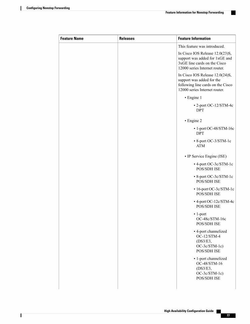
Feature InformationReleasesFeature Name
This feature was introduced.
In Cisco IOS Release 12.0(23)S,support was added for 1xGE and3xGE line cards on the Cisco12000 series Internet router.
In Cisco IOS Release 12.0(24)S,support was added for thefollowing line cards on the Cisco12000 series Internet router.
• Engine 1
• 2-port OC-12/STM-4cDPT
• Engine 2
• 1-port OC-48/STM-16cDPT
• 8-port OC-3/STM-1cATM
• IP Service Engine (ISE)
• 4-port OC-3c/STM-1cPOS/SDH ISE
• 8-port OC-3c/STM-1cPOS/SDH ISE
• 16-port OC-3c/STM-1cPOS/SDH ISE
• 4-port OC-12c/STM-4cPOS/SDH ISE
• 1-portOC-48c/STM-16cPOS/SDH ISE
• 4-port channelizedOC-12/STM-4(DS3/E3,OC-3c/STM-1c)POS/SDH ISE
• 1-port channelizedOC-48/STM-16(DS3/E3,OC-3c/STM-1c)POS/SDH ISE
High Availability Configuration Guide 77
Configuring Nonstop ForwardingFeature Information for Nonstop Forwarding
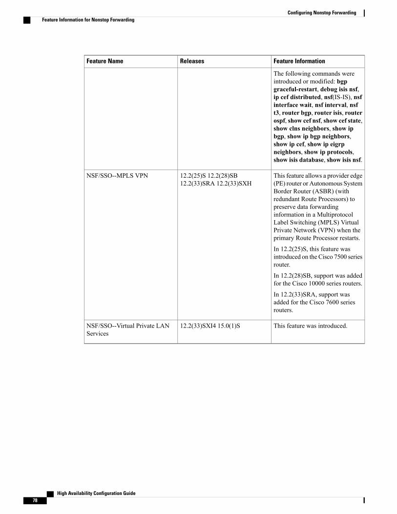
Feature InformationReleasesFeature Name
The following commands wereintroduced or modified: bgpgraceful-restart, debug isis nsf,ip cef distributed, nsf(IS-IS), nsfinterface wait, nsf interval, nsft3, router bgp, router isis, routerospf, show cef nsf, show cef state,show clns neighbors, show ipbgp, show ip bgp neighbors,show ip cef, show ip eigrpneighbors, show ip protocols,show isis database, show isis nsf.
This feature allows a provider edge(PE) router or Autonomous SystemBorder Router (ASBR) (withredundant Route Processors) topreserve data forwardinginformation in a MultiprotocolLabel Switching (MPLS) VirtualPrivate Network (VPN) when theprimary Route Processor restarts.
In 12.2(25)S, this feature wasintroduced on the Cisco 7500 seriesrouter.
In 12.2(28)SB, support was addedfor the Cisco 10000 series routers.
In 12.2(33)SRA, support wasadded for the Cisco 7600 seriesrouters.
12.2(25)S 12.2(28)SB12.2(33)SRA 12.2(33)SXH
NSF/SSO--MPLS VPN
This feature was introduced.12.2(33)SXI4 15.0(1)SNSF/SSO--Virtual Private LANServices
High Availability Configuration Guide78
Configuring Nonstop ForwardingFeature Information for Nonstop Forwarding
C H A P T E R 4Performing an In Service Software Upgrade
This module describes the In Service Software Upgrade (ISSU) process and provides configuration examplesfor ISSU on Cisco ASR 1000 Series routers.
• Finding Feature Information, page 79
• Information About Performing an ISSU, page 79
• How to Perform an ISSU, page 81
• Configuration Examples for Performing an ISSU, page 81
• Additional References, page 82
• Feature Information for Performing an XE ISSU, page 84
Finding Feature InformationYour software release may not support all the features documented in this module. For the latest caveats andfeature information, see Bug Search Tool and the release notes for your platform and software release. Tofind information about the features documented in this module, and to see a list of the releases in which eachfeature is supported, see the feature information table.
Use Cisco Feature Navigator to find information about platform support and Cisco software image support.To access Cisco Feature Navigator, go to www.cisco.com/go/cfn. An account on Cisco.com is not required.
Information About Performing an ISSU
ISSU Process OverviewISSU allows Cisco software to be upgraded or downgraded, at a router level, while the system continues toforward packets. ISSU takes advantage of the Cisco high availability infrastructure--Cisco NSF with SSOand hardware redundancy--and eliminates downtime associated with software upgrades or version changesby allowing updates while the system remains in service. Cisco high availability features combine to lower
High Availability Configuration Guide 79
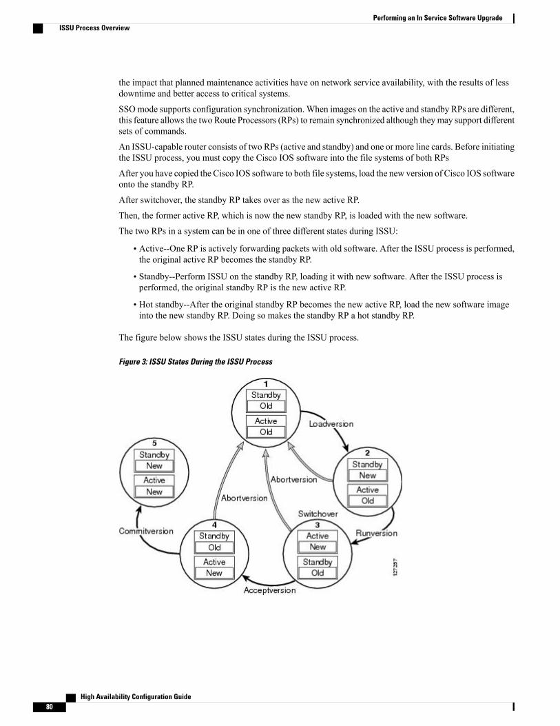
the impact that planned maintenance activities have on network service availability, with the results of lessdowntime and better access to critical systems.
SSOmode supports configuration synchronization. When images on the active and standby RPs are different,this feature allows the two Route Processors (RPs) to remain synchronized although they may support differentsets of commands.
An ISSU-capable router consists of two RPs (active and standby) and one or more line cards. Before initiatingthe ISSU process, you must copy the Cisco IOS software into the file systems of both RPs
After you have copied the Cisco IOS software to both file systems, load the new version of Cisco IOS softwareonto the standby RP.
After switchover, the standby RP takes over as the new active RP.
Then, the former active RP, which is now the new standby RP, is loaded with the new software.
The two RPs in a system can be in one of three different states during ISSU:
• Active--One RP is actively forwarding packets with old software. After the ISSU process is performed,the original active RP becomes the standby RP.
• Standby--Perform ISSU on the standby RP, loading it with new software. After the ISSU process isperformed, the original standby RP is the new active RP.
• Hot standby--After the original standby RP becomes the new active RP, load the new software imageinto the new standby RP. Doing so makes the standby RP a hot standby RP.
The figure below shows the ISSU states during the ISSU process.
Figure 3: ISSU States During the ISSU Process
High Availability Configuration Guide80
Performing an In Service Software UpgradeISSU Process Overview
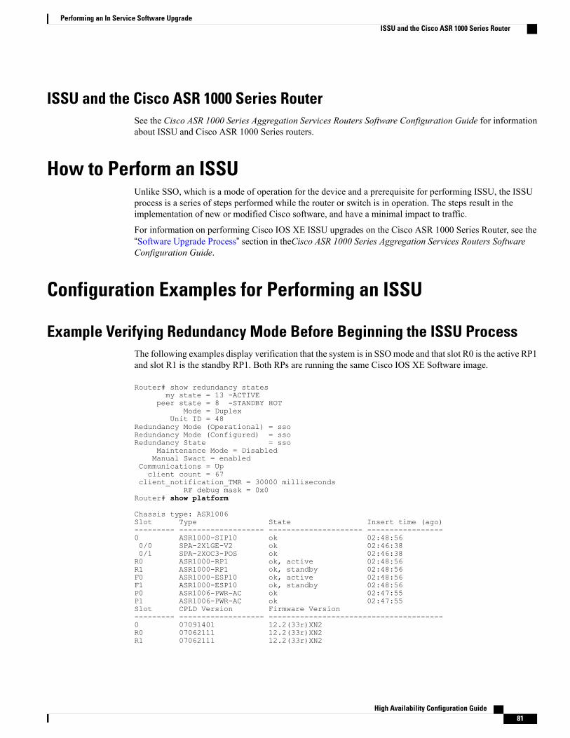
ISSU and the Cisco ASR 1000 Series RouterSee the Cisco ASR 1000 Series Aggregation Services Routers Software Configuration Guide for informationabout ISSU and Cisco ASR 1000 Series routers.
How to Perform an ISSUUnlike SSO, which is a mode of operation for the device and a prerequisite for performing ISSU, the ISSUprocess is a series of steps performed while the router or switch is in operation. The steps result in theimplementation of new or modified Cisco software, and have a minimal impact to traffic.
For information on performing Cisco IOS XE ISSU upgrades on the Cisco ASR 1000 Series Router, see the“Software Upgrade Process” section in theCisco ASR 1000 Series Aggregation Services Routers SoftwareConfiguration Guide.
Configuration Examples for Performing an ISSU
Example Verifying Redundancy Mode Before Beginning the ISSU ProcessThe following examples display verification that the system is in SSOmode and that slot R0 is the active RP1and slot R1 is the standby RP1. Both RPs are running the same Cisco IOS XE Software image.
Router# show redundancy statesmy state = 13 -ACTIVE
peer state = 8 -STANDBY HOTMode = Duplex
Unit ID = 48Redundancy Mode (Operational) = ssoRedundancy Mode (Configured) = ssoRedundancy State = sso
Maintenance Mode = DisabledManual Swact = enabled
Communications = Upclient count = 67
client_notification_TMR = 30000 millisecondsRF debug mask = 0x0
Router# show platform
Chassis type: ASR1006Slot Type State Insert time (ago)--------- ------------------- --------------------- -----------------0 ASR1000-SIP10 ok 02:48:560/0 SPA-2X1GE-V2 ok 02:46:380/1 SPA-2XOC3-POS ok 02:46:38R0 ASR1000-RP1 ok, active 02:48:56R1 ASR1000-RP1 ok, standby 02:48:56F0 ASR1000-ESP10 ok, active 02:48:56F1 ASR1000-ESP10 ok, standby 02:48:56P0 ASR1006-PWR-AC ok 02:47:55P1 ASR1006-PWR-AC ok 02:47:55Slot CPLD Version Firmware Version--------- ------------------- ---------------------------------------0 07091401 12.2(33r)XN2R0 07062111 12.2(33r)XN2R1 07062111 12.2(33r)XN2
High Availability Configuration Guide 81
Performing an In Service Software UpgradeISSU and the Cisco ASR 1000 Series Router
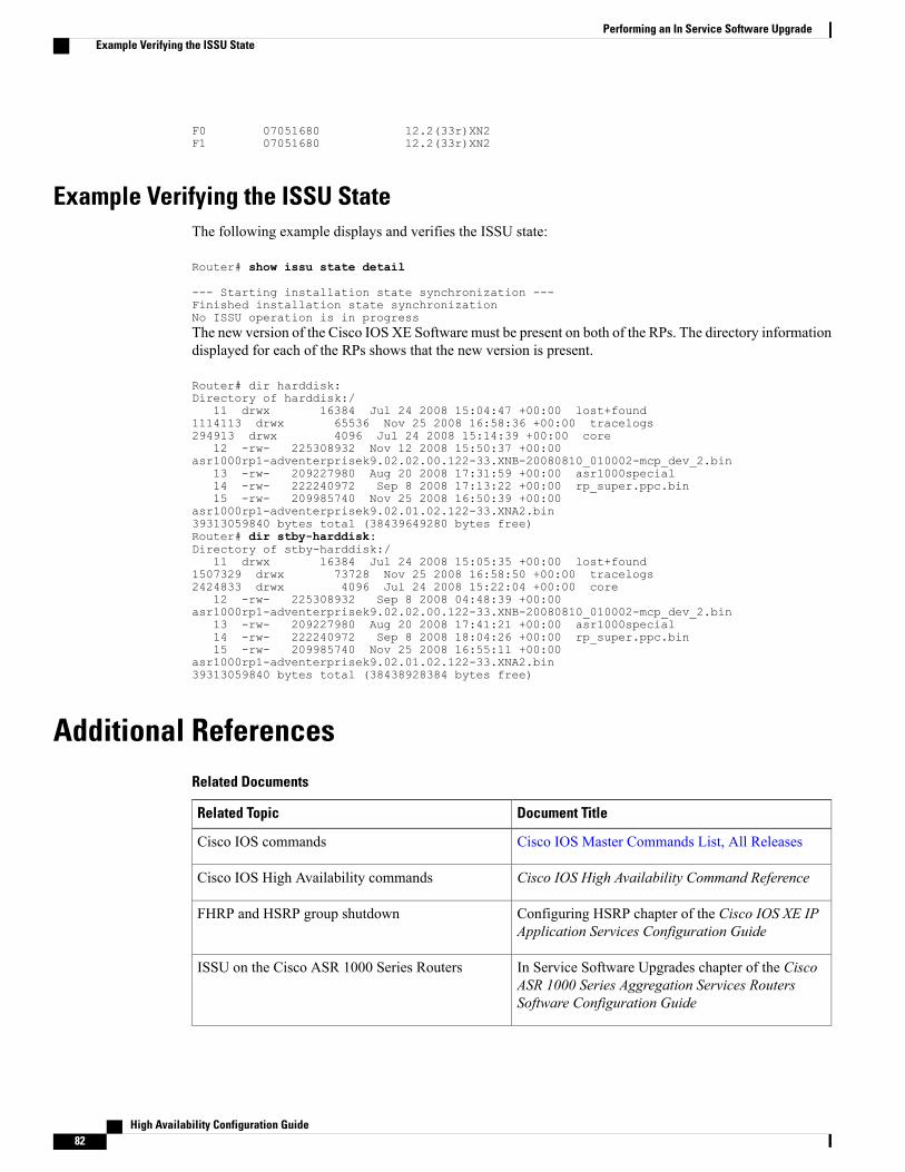
F0 07051680 12.2(33r)XN2F1 07051680 12.2(33r)XN2
Example Verifying the ISSU StateThe following example displays and verifies the ISSU state:
Router# show issu state detail
--- Starting installation state synchronization ---Finished installation state synchronizationNo ISSU operation is in progressThe new version of the Cisco IOS XE Software must be present on both of the RPs. The directory informationdisplayed for each of the RPs shows that the new version is present.
Router# dir harddisk:Directory of harddisk:/
11 drwx 16384 Jul 24 2008 15:04:47 +00:00 lost+found1114113 drwx 65536 Nov 25 2008 16:58:36 +00:00 tracelogs294913 drwx 4096 Jul 24 2008 15:14:39 +00:00 core
12 -rw- 225308932 Nov 12 2008 15:50:37 +00:00asr1000rp1-adventerprisek9.02.02.00.122-33.XNB-20080810_010002-mcp_dev_2.bin
13 -rw- 209227980 Aug 20 2008 17:31:59 +00:00 asr1000special14 -rw- 222240972 Sep 8 2008 17:13:22 +00:00 rp_super.ppc.bin15 -rw- 209985740 Nov 25 2008 16:50:39 +00:00
asr1000rp1-adventerprisek9.02.01.02.122-33.XNA2.bin39313059840 bytes total (38439649280 bytes free)Router# dir stby-harddisk:Directory of stby-harddisk:/
11 drwx 16384 Jul 24 2008 15:05:35 +00:00 lost+found1507329 drwx 73728 Nov 25 2008 16:58:50 +00:00 tracelogs2424833 drwx 4096 Jul 24 2008 15:22:04 +00:00 core
12 -rw- 225308932 Sep 8 2008 04:48:39 +00:00asr1000rp1-adventerprisek9.02.02.00.122-33.XNB-20080810_010002-mcp_dev_2.bin
13 -rw- 209227980 Aug 20 2008 17:41:21 +00:00 asr1000special14 -rw- 222240972 Sep 8 2008 18:04:26 +00:00 rp_super.ppc.bin15 -rw- 209985740 Nov 25 2008 16:55:11 +00:00
asr1000rp1-adventerprisek9.02.01.02.122-33.XNA2.bin39313059840 bytes total (38438928384 bytes free)
Additional ReferencesRelated Documents
Document TitleRelated Topic
Cisco IOS Master Commands List, All ReleasesCisco IOS commands
Cisco IOS High Availability Command ReferenceCisco IOS High Availability commands
Configuring HSRP chapter of the Cisco IOS XE IPApplication Services Configuration Guide
FHRP and HSRP group shutdown
In Service Software Upgrades chapter of the CiscoASR 1000 Series Aggregation Services RoutersSoftware Configuration Guide
ISSU on the Cisco ASR 1000 Series Routers
High Availability Configuration Guide82
Performing an In Service Software UpgradeExample Verifying the ISSU State
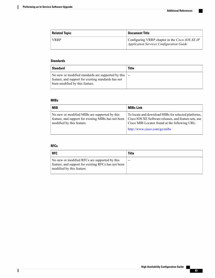
Document TitleRelated Topic
Configuring VRRP chapter in the Cisco IOS XE IPApplication Services Configuration Guide
VRRP
Standards
TitleStandard
--No new or modified standards are supported by thisfeature, and support for existing standards has notbeen modified by this feature.
MIBs
MIBs LinkMIB
To locate and downloadMIBs for selected platforms,Cisco IOSXE Software releases, and feature sets, useCisco MIB Locator found at the following URL:
http://www.cisco.com/go/mibs
No new or modified MIBs are supported by thisfeature, and support for existing MIBs has not beenmodified by this feature.
RFCs
TitleRFC
--No new or modified RFCs are supported by thisfeature, and support for existing RFCs has not beenmodified by this feature.
High Availability Configuration Guide 83
Performing an In Service Software UpgradeAdditional References
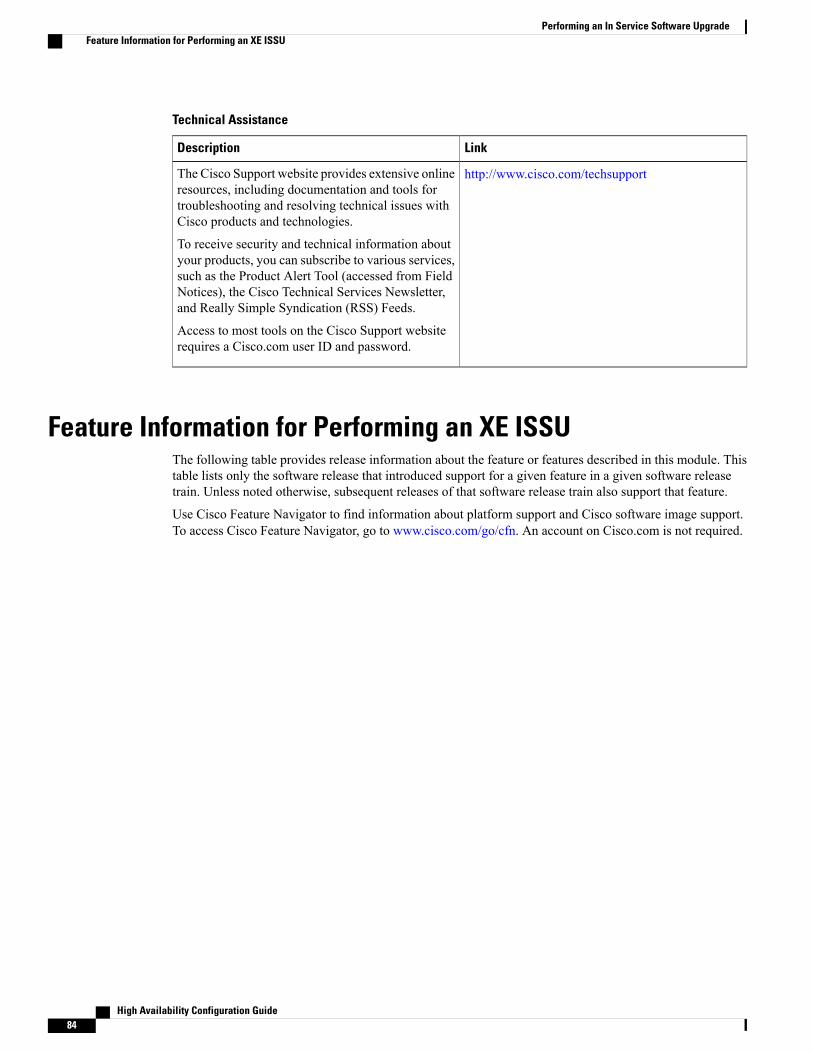
Technical Assistance
LinkDescription
http://www.cisco.com/techsupportThe Cisco Support website provides extensive onlineresources, including documentation and tools fortroubleshooting and resolving technical issues withCisco products and technologies.
To receive security and technical information aboutyour products, you can subscribe to various services,such as the Product Alert Tool (accessed from FieldNotices), the Cisco Technical Services Newsletter,and Really Simple Syndication (RSS) Feeds.
Access to most tools on the Cisco Support websiterequires a Cisco.com user ID and password.
Feature Information for Performing an XE ISSUThe following table provides release information about the feature or features described in this module. Thistable lists only the software release that introduced support for a given feature in a given software releasetrain. Unless noted otherwise, subsequent releases of that software release train also support that feature.
Use Cisco Feature Navigator to find information about platform support and Cisco software image support.To access Cisco Feature Navigator, go to www.cisco.com/go/cfn. An account on Cisco.com is not required.
High Availability Configuration Guide84
Performing an In Service Software UpgradeFeature Information for Performing an XE ISSU
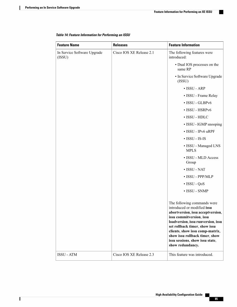
Table 14: Feature Information for Performing an ISSU
Feature InformationReleasesFeature Name
The following features wereintroduced:
• Dual IOS processes on thesame RP
• In Service Software Upgrade(ISSU)
• ISSU - ARP
• ISSU - Frame Relay
• ISSU - GLBPv6
• ISSU - HSRPv6
• ISSU - HDLC
• ISSU - IGMP snooping
• ISSU - IPv6 uRPF
• ISSU - IS-IS
• ISSU - Managed LNSMPLS
• ISSU - MLD AccessGroup
• ISSU - NAT
• ISSU - PPP/MLP
• ISSU - QoS
• ISSU - SNMP
The following commands wereintroduced or modified issuabortversion, issu acceptversion,issu commitversion, issuloadversion, issu runversion, issuset rollback timer, show issuclients, show issu comp-matrix,show issu rollback timer, showissu sessions, show issu state,show redundancy.
Cisco IOS XE Release 2.1In Service Software Upgrade(ISSU)
This feature was introduced.Cisco IOS XE Release 2.3ISSU - ATM
High Availability Configuration Guide 85
Performing an In Service Software UpgradeFeature Information for Performing an XE ISSU

Feature InformationReleasesFeature Name
This feature was introduced forCisco ASR 1000 SeriesAggregation Services Routers.
Cisco IOS XE Release 3.1SISSU - HSRPv6 on VRF interfaces
This feature was introduced.Cisco IOS XE Release 2.5ISSU - Multicast MPLS VPN
High Availability Configuration Guide86
Performing an In Service Software UpgradeFeature Information for Performing an XE ISSU
C H A P T E R 5AAA High Availability Support for Local PPPoXSessions
This feature enhances the authentication, authorization, and accounting (AAA) capability to meet highavailability (HA) criteria for locally terminated Point-to-Point Protocol (PPP) over Ethernet (PPPoE) andPPPoEoX sessions, whereX represents VLANorQinQ. The following FeatureManager features are supportedin this implementation of AAA HA:
• Absolute (session) timeout
• Idle timeout
• Access control lists (ACLs)
• ACL Filter
• Quality of service (QoS)
• Finding Feature Information, page 87
• Restrictions for AAA High Availability Support for Local PPPoX Sessions, page 88
• Information About AAA High Availability Support for Local PPPoX Sessions, page 88
• How to Configure AAA High Availability Support for Local PPPoX Sessions, page 90
• Additional References, page 91
• Feature Information for AAA High Availability Support for Local PPPoX Sessions, page 93
Finding Feature InformationYour software release may not support all the features documented in this module. For the latest caveats andfeature information, see Bug Search Tool and the release notes for your platform and software release. Tofind information about the features documented in this module, and to see a list of the releases in which eachfeature is supported, see the feature information table.
Use Cisco Feature Navigator to find information about platform support and Cisco software image support.To access Cisco Feature Navigator, go to www.cisco.com/go/cfn. An account on Cisco.com is not required.
High Availability Configuration Guide 87
Restrictions for AAA High Availability Support for Local PPPoXSessions
• If an administrator changes the protocol of a server group (for example, from RADIUS to TACACS+),HA will not be available for sessions configured to use that server group.
• IP sessions are not supported in this implementation of AAA HA.
• This implementation of AAA HA supports only locally terminated PPPoX sessions, including thefollowing:
• PPP over Ethernet (PPPoE)
• PPPoE terminated into a multiprotocol label switching (MPLS) virtual private network (VPN)
• PPPoEoE 802.1q into MPLS VPN
• PPPoEoE 802.1q-in-q into MPLS VPN
• Dynamic Host Configuration Protocol (DHCP) VPN ID option 82
• Per VPN AAA
• The following Feature Manager features are not supported in this implementation of AAA HA:
• Prepaid Time Monitor
• Prepaid Volume Monitor
• L4 Redirect
• Traffic Classification
• Portbundle Hostkey
• IPv6 DHCP from AAA
Information About AAA High Availability Support for LocalPPPoX Sessions
AAA HA EnhancementCisco HA delivers carrier grade reliability with Cisco devices running Cisco IOS XE software. Carrier grademeans that service disruption because of outages, service upgrades, or other maintenance activities on CiscoIOS XE platforms are rarely experienced. To achieve this level of service, Cisco uses two route processorsto manage and control the sessions and services for each device. One processor is active and the other is instandby mode, ready to provide backup. A transition from the active processor to the standby processor istransparent to the end user, but not necessarily to the service provider.
The router must maintain the following information during transient component failures:
High Availability Configuration Guide88
AAA High Availability Support for Local PPPoX SessionsRestrictions for AAA High Availability Support for Local PPPoX Sessions
• Authentication status of clients
• Authorization status
• Accounting and billing information
To maintain this information during transitions to the standby processor, Cisco IOS XE software uses an HAreplay model to re-create as much state and database information as possible between the active and standbydevices. The HA replay model works within existing external AAA server protocols to achieve the desiredbehavior.
HA and AuthenticationFor authentication, only the following state information is maintained: knowledge that a session authenticatedon the active processor need not be reauthenticated on the standby processor. Each authentication protocol,such as local, TACACS+, or RADIUS, responds in its protocol-specific way to an authentication request froma standby device. All AAA client authentication replies on a standby device should be successful.
HA and AuthorizationThe HA process for authorization data is different from the authentication process. The AAA server cachesthe authorization responses for the sessions in order to provide the appropriate authorization attributes to AAAclients during a session replay. AAA clients use the authorization attributes to create a session copy on thestandby route processor.
HA and AccountingThe AAA HA accounting framework takes advantage of existing AAA features such as system accountingand periodic accounting to limit the loss of accounting and billing information caused by a switchover betweenan active processor and a standby processor.
System AccountingSystem accounting is a separate accounting capability that informs AAA servers about the state of a clientdevice, such as a router. The AAA server receives a “System-Off” message when a controlled restart takesplace on a client device. The message notifies the AAA server to clear any active sessions being managed forthe specified client. When the client restarts and becomes available for new sessions, the AAA server receivesa “System-On” message. The “System-On” message is also sent following uncontrolled restarts caused bydevice failures or other events that do not generate a “System-Off” message. In either case, the AAA serverno longer maintains any active sessions for the specified client device. The server bills or accounts for thesessions prior to the “System-On” message and starts a new session.
AAA’s accounting HA solution does not add any new requirements to system accounting for AAA servers.Any switchover will look like a very fast, minimally disruptive outage. Although end users do not experienceany loss of service during an HA switchover, AAA servers reset their sessions and restart accounting for allswitched-over sessions.
High Availability Configuration Guide 89
AAA High Availability Support for Local PPPoX SessionsHA and Authentication
Periodic AccountingYou can use periodic accounting to dynamically update records of session utilization for billing purposes.Periodic accountingminimizes the loss of usage statistics. HA does not eliminate the need to configure periodicaccounting on a device if you require dynamic usage statistics for billing purposes. To achieve the HA levelof reliability, the existing network topology configuration must be maintained.
How to Configure AAA High Availability Support for Local PPPoXSessions
Configuring AAA High Availability Support for Local PPPoX SessionsThere are no configuration tasks associated with this feature. If you maintain your network topology for HA,then the AAA functions automatically participate in the HA feature for locally terminated PPPoX sessions.
Troubleshooting an AAA High Availability Configuration
SUMMARY STEPS
1. enable2. debug aaa redundancy3. disable
DETAILED STEPS
PurposeCommand or Action
Enters the privileged EXEC mode.enableStep 1
Example:
Router> enable
• Enter your password, if prompted to do so.
Displays AAA synchronization data for the sessionsynchronization to the standby device.
debug aaa redundancy
Example:
Router# debug aaa redundancy
Step 2
Exits to user EXEC mode.disable
Example:
Router# disable
Step 3
High Availability Configuration Guide90
AAA High Availability Support for Local PPPoX SessionsHow to Configure AAA High Availability Support for Local PPPoX Sessions
Additional ReferencesRelated Documents
Document TitleRelated Topic
Cisco IOS Master Commands List, All ReleasesCisco IOS commands
Cisco IOS Debug Command ReferenceCisco debug commands
Cisco IOS High Availability Command ReferenceCisco IOS High Availability commands
BGP Support for Nonstop Routing (NSR) withStateful Switchover (SSO) module in the Cisco IOSIP Routing: BGP Configuration Guide
BGP support for NSF
EIGRP Nonstop Awareness module in the Cisco IOSIP Routing: EIGRP Configuration Guide
EIGRP NSF awareness
Implementing Multiprotocol BGP for IPv6 modulein the Cisco IOS IPv6 Configuration Guide
IPv6 BGP graceful restart
Implementing RIP for IPv6 module in the Cisco IOSIPv6 Configuration Guide
IPv6 RIP
Implementing Static Routes for IPv6 module in theCisco IOS IPv6 Configuration Guide
IPv6 static routes
Using Ethernet Operations, Administration, andMaintenance module in the Cisco IOS CarrierEthernet Configuration Guide
NSF/SSO--802.3ah OAM Support
Any Transport over MPLS and AToM GracefulRestart module in the Cisco IOSMultiprotocol LabelSwitching Configuration Guide
NSF/SSO--Any Transport over MPLS (AToM)
Configuring Ethernet Local Management Interfaceat a Provider Edge module in the Cisco IOS CarrierEthernet Configuration Guide
NSF/SSO--E-LMI Support
Configuring NSF/SSO--MPLS VPN module in theMPLS Configuration Guide
NSF/SSO--MPLS VPN
NSF/SSO/ISSU Support for VPLS module in theCisco IOS Multiprotocol Label SwitchingConfiguration Guide
Virtual Private LAN Services
High Availability Configuration Guide 91
AAA High Availability Support for Local PPPoX SessionsAdditional References
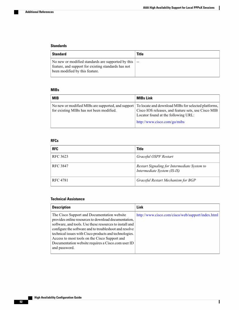
Standards
TitleStandard
--No new or modified standards are supported by thisfeature, and support for existing standards has notbeen modified by this feature.
MIBs
MIBs LinkMIB
To locate and downloadMIBs for selected platforms,Cisco IOS releases, and feature sets, use Cisco MIBLocator found at the following URL:
http://www.cisco.com/go/mibs
No new or modifiedMIBs are supported, and supportfor existing MIBs has not been modified.
RFCs
TitleRFC
Graceful OSPF RestartRFC 3623
Restart Signaling for Intermediate System toIntermediate System (IS-IS)
RFC 3847
Graceful Restart Mechanism for BGPRFC 4781
Technical Assistance
LinkDescription
http://www.cisco.com/cisco/web/support/index.htmlThe Cisco Support and Documentation websiteprovides online resources to download documentation,software, and tools. Use these resources to install andconfigure the software and to troubleshoot and resolvetechnical issues with Cisco products and technologies.Access to most tools on the Cisco Support andDocumentation website requires a Cisco.com user IDand password.
High Availability Configuration Guide92
AAA High Availability Support for Local PPPoX SessionsAdditional References
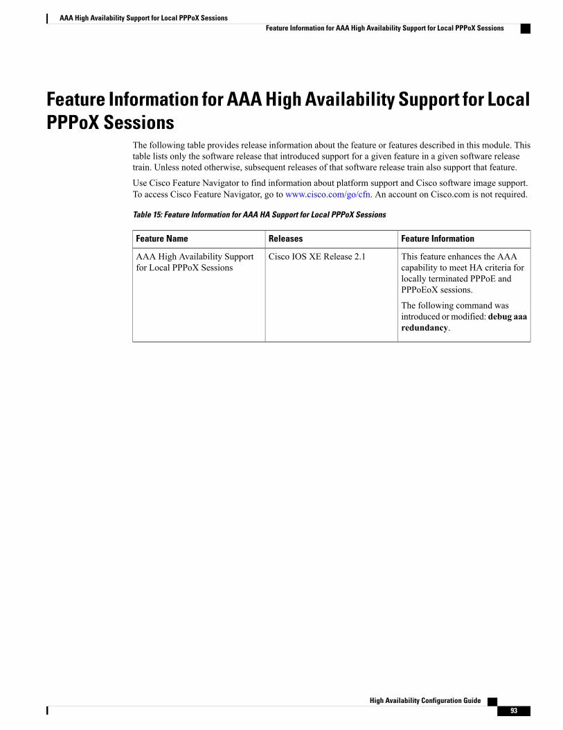
Feature Information for AAA High Availability Support for LocalPPPoX Sessions
The following table provides release information about the feature or features described in this module. Thistable lists only the software release that introduced support for a given feature in a given software releasetrain. Unless noted otherwise, subsequent releases of that software release train also support that feature.
Use Cisco Feature Navigator to find information about platform support and Cisco software image support.To access Cisco Feature Navigator, go to www.cisco.com/go/cfn. An account on Cisco.com is not required.
Table 15: Feature Information for AAA HA Support for Local PPPoX Sessions
Feature InformationReleasesFeature Name
This feature enhances the AAAcapability to meet HA criteria forlocally terminated PPPoE andPPPoEoX sessions.
The following command wasintroduced or modified: debug aaaredundancy.
Cisco IOS XE Release 2.1AAA High Availability Supportfor Local PPPoX Sessions
High Availability Configuration Guide 93
AAA High Availability Support for Local PPPoX SessionsFeature Information for AAA High Availability Support for Local PPPoX Sessions

High Availability Configuration Guide94
AAA High Availability Support for Local PPPoX SessionsFeature Information for AAA High Availability Support for Local PPPoX Sessions


![Cisco Catalyst 3850 Series Switches running IOS-XE …ST] Cisco... · Cisco Catalyst 3850 Series Switches running IOS-XE 3.6.0E and Catalyst 6500 Series Switches running IOS 15.1(2)SY3Security](https://img.pdfslide.us/doc/110x75/5af843227f8b9a8d1c914ead/cisco-catalyst-3850-series-switches-running-ios-xe-st-ciscocisco-catalyst.jpg)