Embed Size (px)
Citation preview

fsmobum
High-accuracy measurement of 240-m distance in anoptical tunnel by use of a compact femtosecond laser
Kaoru Minoshima and Hirokazu Matsumoto
A high-accuracy optical distance meter with a mode-locked femtosecond laser is proposed for distancemeasurements in a 310-m-long optical tunnel. We measured the phase shift of the optical beat com-ponent between longitudinal modes of a mode-locked laser. A high resolution of 50 mm at 240-mdistance was obtained without cyclic error correction. The group refractive index of air is automaticallyextracted to an accuracy of 6 parts per million ~ppm! by two-color measurement with the pulses offundamental and second-harmonic wavelengths. Finally, an absolute mechanical distance of 240 m wasobtained to within 8-ppm accuracy by use of a series of beat frequencies with the advantage of a widerange of intermode frequency, together with the results of the two-color measurement. © 2000 OpticalSociety of America
OCIS codes: 140.4050, 320.7160, 140.3510, 280.3400.
1. Introduction
Significant developments have been made with re-gard to the compactness, portability, and stability offemtosecond lasers.1 These features are attractiveor applications such as high-accuracy distance mea-urements in open fields, which are necessary forany disciplines, for example, shape measurements
f large-scale structures such as buildings and para-olic antennae. An optical distance meter can besed for noncontact and high-resolution measure-ents.2,3 The phase measurement of a sinusoidally
modulated cw laser has been used because a phaseshift with high resolution can be measured. Inter-ferometric methods are not suitable for these appli-cations because they are for displacementmeasurements between two points and require con-tinuously delayed movement. Several methodshave been proposed to obtain modulated waves, forexample, external modulation with an electro-opticmodulator,4 direct modulation of a laser diode, or useof the internal mode beat of a He–Ne laser.5,6 Up tonow, the highest resolution, that is, several microme-ters over a 100-m distance, has been realized by use
The authors are with the National Research Laboratory of Me-trology, 1-1-4 Umezono, Tsukuba, Ibaraki 305-8563, Japan. Thee-mail address for K. Minoshima is [email protected].
Received 29 November 1999; revised manuscript received 14July 2000.
0003-6935y00y305512-06$15.00y0© 2000 Optical Society of America
5512 APPLIED OPTICS y Vol. 39, No. 30 y 20 October 2000
of 28-GHz modulation with the method outlined inRef. 4. However, with methods that use a modula-tor, the correction of cyclic error2 is necessary beforesuch high resolution can be achieved. The mainsources of cyclic error are electrical crosstalk thatoriginates from the modulator and the internal opti-cal multipath that is due to the complexity of thesetup.
Use of the mode beat of a laser is a method bywhich one can suppress the cyclic error.5,6 Becausea femtosecond mode-locked laser has a wide rangeand a large number of stable optical frequency modes,a frequency beat higher than in the gigahertz rangecan be easily utilized with high stability. Here wepropose a high-accuracy optical distance meter with amode-locked femtosecond laser, without the necessityfor cyclic error correction and with the advantages oftwo-color measurement, absolute distance measure-ment, and use of a broad spectrum, as described inSection 2. The femtosecond distance meter is ap-plied to distance measurements in a 310-m-long op-tical tunnel.
2. Principle of the Method
For the time domain we used a femtosecond mode-locked optical pulse train that contains pulses withtemporal widths ~FWHM! of 180 fs and 20-ns repeti-tion rate. In contrast, for the frequency domain, op-tical frequency modes appear every 50 MHz over 2THz ~FWHM!. The intermode beats between allpossible pairs provide a wide range of stable electricfrequency components if the pulse train is detected by

tsfrwbHaiitf
iplcgmo
sFmimhtsch1weeTt
i
w
a photoelectronic detector. In this case, the beat fre-quency covers the range from 50 MHz to the tera-hertz region when a detection method is available.For stability we used the square root of Allan vari-ance7 for evaluation, which has been widely used toevaluate the stability of cw lasers. Figure 1 showsthe Allan variance of the repetition frequency of themode-locked laser that is used in this study. The1-GHz difference of the 20th harmonic of the laserrepetition frequency from a reference synthesizerwith 10210 stability was generated by a double-balanced mixer and was measured by a frequencycounter. The signal of the Rb frequency standardwas used as a reference signal for the frequencycounter. The frequencies were sampled ten timesduring each gate time. By changing the gate timefrom 0.01 to 1000 s, we calculated the Allan vari-ances. We determined that stability is in the rangeof 1029 in the short term ~,1 s! and 1027 in the longerm ~,1000 s!; the latter depends on environmentaltability such as temperature. In other words, aemtosecond mode-locked laser is equivalent to a se-ies of wide-ranging and stable-modulated cw opticalaves, and it is attractive for distance measurementsy use of the phase of a modulated optical wave.ere we consider that a modulated optical wave prop-gates at a distance ~D! and returns to the detector atts original position. Then the phase of the wave ~f!s measured relative to the original wave. We ob-ained the distance by using the measured phaserom
~N 1 fy2p! 52f ng D
c. (1)
Here N is the integer part of the phase, c is the speedof light, f is the beat frequency used for measurement,and ng is the group refractive index at the opticalwavelength. The factor of 2 on the right-hand side ofEq. ~1! is necessary because the light makes a roundtrip.
The femtosecond distance meter has several ad-vantages over conventional methods that use a cw
Fig. 1. Stability of the repetition rate of the mode-locked fiberlaser that we used for this study ~second-harmonic wavelength!,
hich was evaluated by the square root of Allan variance.
laser. First, a series of intermode beats in a widefrequency range is available. As a result, a smallamount of cyclic error is expected because the opticaland electrical setups are simple. Moreover, thewide-ranging frequency components up to high fre-quencies can easily be utilized for the measurements.High frequency is required for high resolution be-cause the phase resolution generally limits the mea-surement and higher frequency results in a smallerdistance for the same phase value. Selectable fre-quency is required to determine the absolute dis-tance, without continuous scanning, which meanswithout ambiguity of the integer term N in Eq. ~1!, ass demonstrated in Subsection 4.C. Second, higheak power is attractive for utilization of optical non-inear effects. For this study we performed two-olor measurements by using the second-harmoniceneration to realize self-correction of the environ-ental conditions such as temperature and pressure
f air ~Subsection 4.B!.3,8 Two-color measurement isa powerful tool because it is not subject to preciseestimation of the environmental parameters of air,which is the most serious problem in long-distancemeasurements because they can vary in time andspace. Finally, a broad optical spectrum of thepulse, such as greater than 4 nm FWHM, has theadvantage of insensitivity to sharp absorption lines ofa small amount of gas in air, because absorption linescan result in severe measurement errors by use of anarrow line laser when their wavelengths coincide.
3. Experimental
The measurements were performed in the opticaltunnel of the National Research Laboratory of Me-trology, which is a 310-m-long semiunderground tun-nel covered by soil. It has two 50-m movingcarriages and calibrated base points every 50 m up to310 m. The temperature is stable to within 2 °Cyear round, which makes it suitable for evaluation ofthe new distance meter.
We performed two kinds of experiment, one-color~Subsection 4.A! and two-color ~Subsection 4.B! mea-urements. The experimental setups are shown inigs. 2 and 3. The light source is a femtosecondode-locked fiber laser ~Femtolite-780, IMRA Amer-
ca, Inc.!. The dimensions of the laser head are 193m 3 109 mm 3 82 mm and it is equipped with aandheld electronic controller. The compactness ofhe laser makes it suitable for practical distance mea-urements in open fields. The laser generates twooaxial beams of the fundamental ~v! and second ~2v!armonic with center wavelengths of approximately560 and 780 nm. Both beams have 180-fs temporalidth, 50-MHz repetition rate ~ frep!, and 10-mW av-rage power. For the first one-color measurementxperiment ~Fig. 2!, only the 2v beam was used.he beam was divided into two: one was detected byhe photodetector ~PD2! and the other was used as
the reference. The reference beam was expanded toa diameter of 100 mm by a pair of curved mirrors~CM1 and CM2!, it propagated to a 240-m distancento the tunnel, was reflected by mirrors M1 and M2,
20 October 2000 y Vol. 39, No. 30 y APPLIED OPTICS 5513

2sbcpf
fq
mTCt2trssbst~omcoqa
hLtp
5
and then returned to the delay line. A He–Ne laserbeam was coaxially propagated for alignment pur-poses. The probe beam was detected by the photo-detector ~PD1! after it passed the scanning opticaldelay line. The phase difference between the refer-ence and the probe waves ~f! at specified electricfrequency f was measured by a phasemeter ~vectorvoltmeter HP8508A!. To evaluate the distancemeter, we measured the phase shift by varying theoptical delay, although scanning was not necessaryfor the actual measurement. The scanning lengthwas calibrated in nanometer resolution with an opti-cal interferometer ~HP5500C!.
We carried out the main measurement near f 5 1GHz, which is the 19th harmonic of frep, and theresults obtained at frep ~approximately 50 MHz! andfrep were also used for the absolute distance mea-urement described in Subsection 4.C. In this case,ecause the signal includes a wide range of frequencyomponents, we selected the specified frequency com-onents to be measured by using the variable-requency bandpass filters in the phasemeter.
Fig. 2. Experimental setup for the high-accuracy distance meterwith the intermode beats of a femtosecond mode-locked laser.The laser source generates both fundamental ~v! and second-
armonic ~2v! beams. Here only 2v is used. PD, photodetector;, lens; M, reflecting mirror; CR, corner reflector; BS, beam split-er; DM, dichroic mirror; CM, curved mirror; S, beam stopper; f,hase difference between probe and reference.
Fig. 3. Experimental setup for two-color measurement for self-correction of the group refractive index of air in the distance meterby use of the intermode beats of a femtosecond mode-locked laser.We used the pulses of two wavelengths. The abbreviations meanthe same as in Fig. 2. Mirror M2 spatially reflects a portion of thebeams. When the measurement is taken for 0-m propagation, thelong traveling beams are blocked by S2. In contrast, for 240-mpropagation, the beam that is partially reflected by M2 is blockedby S1.
514 APPLIED OPTICS y Vol. 39, No. 30 y 20 October 2000
Although the bandpass filters do not have sharp pass-bands, the reference signal selects the frequency com-ponent with the highest intensity in the selectedrange. To select a 19th harmonic component, weused a photodetector that gives a local maximumnear 1 GHz for the frequency response. For mea-surements with f 5 frep and 2frep, we used a narrowbandpass filter to select the frequencies. The fre-quency selection is reliable except when there is nolight. The value of the beat frequency ~ f ! is ex-tracted by the measurement of the phase for a fullcycle when the optical delay is varied. In this case,the precise measurement of the cycle is not necessarybecause the frequency should be the harmonic of thefundamental repetition rate of the mode-locked pulsetrain ~ frep!, which was measured by a high-precisionrequency counter. The stability of the beat fre-uency is 1027 throughout the measurement.Next, two-color measurement for self-correction
of the group refractive index of air was performed,as described in Subsection 4.B. The setup shownin Fig. 3 is similar to the one in Fig. 2, except thatwe used beams of both v and 2v and took two
easurements for both 0- and 240-m distances.he beams of both colors, which expand by use ofM1 and CM2, propagate up to 240 m into the
unnel, are reflected back, and are used for the40-m distance measurement. Spatially, a part ofhe beam is blocked by reflective mirror M2, andeflected beams are used for the 0-m distance mea-urement. The other beams are blocked by beamtopper S1 or S2. For each measurement, probeeams contain both v and 2v beams, which areeparated by a dichroic mirror ~DM! and are de-ected by PD1 and PD2. The reference detectorPD3! responds only to 2v. We obtained four kindsf phase difference from the references, which wereeasured at 0- and 240-m distances for both two-
olor v and 2v beams. We scanned the delay linence in advance to confirm the modulation fre-uency, but this scanning is not necessary for anctual measurement of the distance.
4. Results and Discussions
A. High-Resolution Distance Measurement with aOne-Color Setup
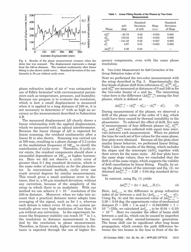
First we measured the phase for the 240-m distanceby using the one-color setup. To evaluate the reso-lution, we added a small displacement to the 240-mdistance by continuously scanning the optical delayline. Figure 4 shows the result of the displacement~DD!, which was calculated with Eq. ~1! from themeasured phase shift at f 5 0.9453017 GHz ~19thharmonic of frep!. The group refractive index of airng is calculated by
ng 5 np 2 l]np
]l, (2)
where ng and np are the group and the phase re-fractive indices of air at wavelength l. Here, the
c4
lwBllaa
tiTt
a
v
fvtfsTtttdoio
3d
3
bTpt
Table 1. Linear Fitting Results of the Phases by Two-Color
phase refractive index of air np was estimated byuse of Edlen formulas9 with environmental param-eters such as temperature, pressure, and humidity.Because our purpose is to evaluate the resolution,which is how a small displacement is measuredwhen it is applied to a long distance of 240 m, it isnot necessary to determine ng with as high an ac-uracy as the measurement described in Subsection.B.The measured displacement DD clearly shows a
inear relationship with the applied displacement,hich we measured with an optical interferometer.ecause the linear change of DD is expected for
inear scanning, the residual nonlinearity after ainear fit is also shown. Scanning was carried outt 500 mm, resulting in a phase change of 3.3 cyclest the modulation frequency of 19frep to clarify the
contribution of cyclic error. Therefore, if cyclic er-ror exists, the residual components should show asinusoidal dependence at 19frep or higher harmon-ics. Here we did not observe a cyclic error ofgreater than 0.1 deg standard deviation, which isthe same order of nonlinearity as for the phaseme-ter. In conventional methods, cyclic error canreach several degrees for similar measurements.This result gives a small nonlinear error in dis-tance, that is, a 50-mm standard deviation, withoutany correction, because of the simplicity of thesetup in which there is no modulator. With ourmethod we can achieve 2 3 1027 resolution of the240-m distance. Moreover, when we take into ac-count that a practical distance meter adopts timeaveraging of the signal, such as for 1 s, whereaseach datum is taken every 10 ms, our system po-tentially gives very high resolution of less than 10mm without any correction. In the experiment, be-cause the frequency stability can reach 1029 in 1 s,he resolution in distance measurement is lim-ted by the resolution in phase measurement.herefore, in future study, higher resolution in dis-ance is expected through the use of higher fre-
Fig. 4. Results of the phase measurement ~crosses! when thedelay line was scanned. The displacement represents a changefrom the 240-m distance. The residual nonlinearity after linearfitting is also shown ~solid curve!. Standard deviation of the non-linearity is 50 mm without cyclic error.
quency components, even with the same phaseresolution.
B. Two-Color Measurement for Self-Correction of theGroup Refractive Index of Air
Next we performed the two-color measurement withthe setup described in Fig. 3. Experimentally, thefour kinds of phase shift from references fv
0, fv240, f2v
0 ,nd f2v
240 are measured at distances of 0 and 240 m forthe two-color beams of v and 2v. The interestingalue here is the difference ~Df2v2v
24020! among the fourphases, which is defined as
Df2v2v24020 5 ~f2v
240 2 f2v0 ! 2 ~fv
240 2 fv0!. (3)
During measurement of the phases, we observed adrift of the phase value of the order of 1 deg, whichcould have been caused by thermal instability in thephasemeter. To subtract the effect of drift, five setsof measurements of four different phases ~fv
0, fv240,
2v0 , and f2v
240! were collected with equal time inter-als between each measurement. When we plottedhe time for each set of five values for the same phase,our plots were obtained. Because all the plots showimilar linear behavior, we performed linear fitting.able 1 lists the results of the fitting, which includeshe slopes and the intercepts @f~0!#, together withheir errors for the same units. All four plots havehe same slope values; thus we concluded that therift is of the same origin, which supports the validityf drift cancellation by linear fitting. Finally, by us-ng the phase values of the intercept and Eq. ~3!, webtained Df2v2v
24020 5 3.28 6 0.04 deg standard devia-tion.
In contrast, using Eq. ~1! yields
Df2v2v24020 5 2p 3 Dn2v2v
g D fyc. (4)
Here, Dn2v2vg is the difference in group refractive
index of air between v and 2v ~Dn2v2vg 5 n2v
g 2 nvg!.
Using Eq. ~4! and the measured value of Df2v2v24020 5
.28 6 0.04 deg, the approximate value of mechanicalistance D 5 239 6 1 m and f 5 ~0.9453000 6 1 3
1027! GHz, we calculated Dn2v2vg to be ~6.04 6 0.10!
1026. Here we consider the effect of beam shiftbetween v and 2v, which can be caused by imperfecteam overlap after second-harmonic generation.he beam shift can be significant after long beamropagation, which creates the path difference be-ween the two beams in the lens in front of the de-
Measurements
Phasef~0!~deg!
StandardDeviation
of f~0!Slope~a.u.!
StandardDeviationof Slope
f2v240 223.78 0.02 20.033 0.003
f2v0 119.24 0.03 20.033 0.006
fv240 2141.33 0.02 20.027 0.003
fv0 4.97 0.01 20.033 0.002
Df2v2v24020 3.28 0.04 — —
20 October 2000 y Vol. 39, No. 30 y APPLIED OPTICS 5515

ecpat3ecc
e
trppc
ewwfm
u
setawm
5
tectors. Because the refractive-index difference ofglass is 0.8 3 1022, which is much larger than that of1025 for air, the beam shift could cause an error in thestimation of the refractive index of air in the two-olor measurement. Here, by using the result of areliminary measurement, we were able to estimatebeam shift of approximately 50 mm at the surface of
he plano–convex lens with 100-mm diameter and00-mm focal length. Then the path-length differ-nce in glass can be estimated as 4 mm by geometriconsiderations. The optical path difference of two-olor beams was obtained as 3 3 1022 mm by use of
the refractive-index difference of BK7 glass. Be-cause the total measurement length in air is 480 mfor a round trip, the optical path difference of 3 31022 mm gives an error of 0.6 3 1027 in the mea-surement of Dn2v2v
g of air. Finally, by adding anrror of the order of 1 3 1027, we obtained Dn2v2v
g ofair as ~6.0 6 0.2! 3 1026 by use of the two-colormeasurement procedure.
Here we can assume that the A coefficient of thegroup refractive index of air that is determined by Eq.~5! is constant because the dispersion relation of therefractive index does not change within the practicalconditions10:
A 5n2v
g 2 1Dn2v2v
g . (5)
We estimated the variation of the A coefficientthrough calculations under different conditions of airusing Edlen’s formulas for the phase refractive indexof air9 and Eq. ~2!. Even when the variations oftemperature, pressure, and humidity are 10 K, 20hPa, and 20%, respectively, which occur under ex-treme conditions, the value of A remains at 47.8 witha variation of 0.6%.
Then the group refractive index for the second-harmonic wavelength n2v
g was obtained as Eq. ~6! byuse of the values of Dn2v2v
g and A. We simulta-neously estimated n2v
g with Eq. ~7! and Edlen’s for-mulas with the values of temperature, pressure, andhumidity of air measured at specified positions in thetunnel:
~n2vg 2 1!experiment 5 ~287 6 10!31026, (6)
~n2vg 2 1!Edlen 5 ~277 6 6! 3 1026. (7)
The uncertainty in Eq. ~7! is estimated when thevariations of temperature, pressure, and humidityare 2 K, 10 hPa, and 10%, respectively, taking intoaccount variations of the environmental parametersin space along the optical path and eventually duringall the measurements. The values of the refractiveindices in Eqs. ~6! and ~7! agree with 6 ppm ~parts permillion!, which confirms the applicability of the pro-posed method. Here we note that the value in Eq.~6! was obtained without any assumptions with re-gard to environmental conditions such as tempera-ture, pressure, or humidity, whereas it was necessary
516 APPLIED OPTICS y Vol. 39, No. 30 y 20 October 2000
for us to assume the values to obtain the estimatedvalue in Eq. ~7!.
C. Absolute Mechanical Distance Measurement
Finally, we obtained the absolute mechanical dis-tance using one-color measurements at frep and 2frep,together with the results of the two-color measure-ments outlined in Subsection 4.B. Absolute dis-tance is without ambiguity of integer N in Eq. ~1!, andhe mechanical distance is without ambiguity of theefractive index of air. The process to obtain thesearameters is as follows. First, we measured thehase difference between 0 and 240 m using a one-olor beam at f 5 frep and 2frep. By mechanical mea-
surement to within 1 m, we determined theapproximate distance to be D 5 239 6 1 m, and thequivalent wavelength of the modulation opticalave at frep is approximately 3 m for a round trip,hich is greater than the uncertainty of D. There-
ore the absolute distance is D 5 239.956 and 239.951for f 5 frep and 2frep, respectively. The discrep-
ancy originates from the drift of the phase of the orderof 1 deg, which gives an error of 0.01 m. Here thegroup refractive index is used to calculate the me-chanical distance, but 100-ppm accuracy is enough toextract the distance to within an error of 0.01 m; thus,detailed information about the environmental condi-tion is not necessary. In summary, we obtained theabsolute mechanical distance of D 5 239.95 6 0.01 m
sing a one-color beam at f 5 frep and 2frep.Next, by use of the phase difference between f2v
240
and f2v0 , together with the experimental value of n2v
g
@Eq. ~6!#, all of which were obtained by two-color mea-urement at f 5 0.9453000 GHz in Subsection 4.B, wextracted the absolute mechanical distance becausehe equivalent wavelength of the modulated wave ispproximately 150 mm, and we determined D toithin 10-mm accuracy through previous measure-ents taken with frep and 2frep. Finally, we ob-
tained D 5 239.943 6 0.002 m to within 8-ppmaccuracy. Note that the absolute distance was ob-tained without continuous scanning of the entire 240-m-long optical path because of the above-mentionedstep-by-step measurements with the selectable fre-quency components in the mode-locked pulse laser.Moreover, by taking advantage of the two-color mea-surement, we were able to extract the mechanicaldistance without assuming environmental conditionssuch as temperature and pressure, which can varytemporally and even spatially along the optical path.
5. Conclusions
We have developed a high-accuracy distance meterusing the phase measurement of intermode beat com-ponents of a femtosecond mode-locked pulse train.The instrument can be used to measure a distance of240 m with a high resolution of 50 mm without anycorrection of the cyclic error. The distance measure-ment taken with two-color pulses self-corrects environ-mental conditions such as temperature and pressure ofair, enabling the group refractive index of air to beobtained to within 6-ppm accuracy. A series of mea-

2. J. Rueger, Electronic Distance Measurement ~Springer-Verlag,
surements with various beat frequencies provides ab-solute distance measurements without the need forcontinuous scanning to determine the integer part inphase. Finally, we obtained the absolute mechanicaldistance of 240 m with 8-ppm accuracy only by use ofa series of femtosecond distance measurements. Inthe future, it will be possible to achieve higher resolu-tion by use of higher frequency components that al-ready exist in the laser source. One can expectmicrometer resolution by using a 10-GHz component.We thank Takeshi Yasui of Osaka University forhelping us to create Fig. 1. K. Minoshima thanksKatuo Seta and Ichiro Fujima for the informative dis-cussions and for supplying the experimental equip-ment. This research is supported by the designatedresearch project for Femtosecond Technology, Indus-trial Science and Technology Frontier Program,Agency of Industrial Science and Technology, Ministryof International Trade and Industry, Japan.
References1. M. E. Fermann, A. Galvanauskas, G. Sucha, and D. Harter,
“Fiber lasers for ultrafast optics,” J. Appl. Phys. B 65, 259–275~1997!.
New York, 1990!.3. P. Bender, “Laser measurements of long distances,” Proc.
IEEE 55, 1039–1045 ~1967!.4. I. Fujima, S. Iwasaki, and K. Seta, “High-resolution distance
meter using optical intensity modulation at 28 GHz,” Meas.Sci. Technol. 9, 1049–1052 ~1998!.
5. K. Seta, T. Oh’ishi, and S. Seino, “Optical distance measure-ment using inter-mode beat of laser,” Jpn. J. Appl. Phys. 24,1374–1375 ~1985!.
6. R. Balhorn, F. Lebovsky, and D. Ullrich, “Untersuchungenzur Entfermungsmessung mit Stabilisierten Zweifrequenz-lasern,” Technical Report ~Physikalisch-Technischen Bunde-sanstalt Jahresbericht, Braunschweig, Germany, 1974!, pp.151–153.
7. D. Allan, “Statistics of atomic frequency standards,” Proc.IEEE 54, 221–230 ~1966!.
8. K. E. Im, C. S. Gardner, J. B. Abshire, and J. F. McGarry,“Experimental evaluation of the performance of pulsed two-color laser-ranging systems,” J. Opt. Soc. Am. A 4, 820–833~1987!.
9. R. Muijlwijk, “Update of the Edlen formulae for the refractiveindex of air,” Metrologia 25, 189–189 ~1988!.
10. P. Bender and J. Owens, “Correction of optical distance mea-surements for the fluctuating atmospheric index of refraction,”J. Geophys. Res. 70, 2461–2462 ~1965!.
20 October 2000 y Vol. 39, No. 30 y APPLIED OPTICS 5517