Embed Size (px)
Citation preview
3866 IEEE TRANSACTIONS ON VEHICULAR TECHNOLOGY, VOL. 68, NO. 4, APRIL 2019
Hierarchical Radio Resource Allocation for NetworkSlicing in Fog Radio Access Networks
Yaohua Sun , Mugen Peng , Senior Member, IEEE, Shiwen Mao , Fellow, IEEE, and Shi Yan
Abstract—Network slicing in fog radio access networks is recog-nized as a cost-efficient solution to support future diverse use cases.However, with the number of user equipments (UE) fast increasing,the centralized resource allocation architecture for network slic-ing can put heavy burdens on the global radio resource manager(GRRM), and meanwhile slice customization is not easy to achieve.To overcome the two issues, a hierarchical radio resource allocationarchitecture is proposed in this paper, where the GRRM is respon-sible for allocating subchannels to local radio resource managers(LRRMs) in slices, which then allocate the assigned resources totheir UEs. Under this architecture, a hierarchical resource alloca-tion problem is formulated, and the problem is further modeledas a Stackelberg game with the GRRM as the leader and LR-RMs as followers, considering the hierarchy between the GRRMand LRRMs. Due to the NP-hardness of the followers’ problems,a process based on exhaustive search is first proposed to achievethe Stackelberg equilibrium (SE). Nevertheless, when the networkscale is large, achieving SE within limited decision making timeis impractical for game players. Facing this challenge, the GRRMand LRRMs are seen as bounded rational players, and low com-plexity algorithms are developed to help them achieve local optimalsolutions that lead to a weak version of SE. Simulation results showthat there exists a tradeoff between the performance of slices, andthe low complexity algorithms achieve close performance to thatof exhaustive search and outperform other baselines significantly.
Index Terms—Fog radio access networks (F-RANs), networkslicing, radio resource allocation, Stackelberg game.
I. INTRODUCTION
TO BETTER satisfy future communication demands, fogradio access networks (F-RANs) are proposed to achieve
high spectral efficiency, energy efficiency and low latency byfully utilizing the signal processing, resource management and
Manuscript received May 20, 2018; revised October 16, 2018 and January 16,2019; accepted January 20, 2019. Date of publication January 31, 2019; date ofcurrent version April 16, 2019. This work was supported in part by the State Ma-jor Science and Technology Special Project under Grants 2017ZX03001025-006and 2018ZX03001023-005, in part by the National Natural Science Foundationof China under Grants 61831002 and 61728101, in part by the National Programfor Special Support of Eminent Professionals, in part by the National ScienceFoundation for Post-doctoral Scientists of China under Grant 2018M641279,and in part by the US National Science Foundation under Grant CNS-1702957.The review of this paper was coordinated by Dr. A.-C. Pang. (Correspondingauthor: Mugen Peng.)
Y. Sun and S. Yan are with the Key Laboratory of Universal Wireless Commu-nications (Ministry of Education), Beijing University of Posts and Telecommu-nications, Beijing 100876, China (e-mail:, [email protected]; [email protected]).
M. Peng is with the State Key Laboratory of Networking and SwitchingTechnology (SKL-NST), Beijing University of Posts and Telecommunications,Beijing 100876, China (e-mail:,[email protected]).
S. Mao is with the Department of Electrical and Computer Engineering,Auburn University, Auburn, AL 36849 USA (e-mail:,[email protected]).
Digital Object Identifier 10.1109/TVT.2019.2896586
storage capabilities of edge devices [1]. In F-RANs, a user equip-ment (UE) can operate in different communication modes, in-cluding the centralized cloud-RAN mode and the fog accesspoint (FAP) mode. Up to now, some interesting studies havebeen conducted on F-RANs, in terms of performance analysis[2], radio resource allocation [3], the joint design of cloud andedge processing [4], and so on.
On the other hand, as an emerging concept, network slicingis attracting more and more attentions, and is expected to bean efficient and flexible solution to support diverse applicationscenarios with different requirements. With network slicing, aphysical network can be divided into multiple virtual networks,each of which is formed by a set of network functions andresources. When network slicing is conducted in an end-to-endmanner, the RAN part of a network slice is referred to as a RANslice, whose performance is dependent on resource allocation. Incurrent works addressing resource allocation for RAN slicing, acritical aspect is to achieve slice isolation between RAN slices[5], and two different ways are often adopted to achieve thisgoal. The first one is allocating non-overlapping resources todifferent slices [7]–[13], while the second one is ensuring theminimum performance of each slice [14]. By isolation, anychange in one slice will have no impact or at least a little impacton the performance of other slices.
Owing to fog computing, cloud computing and heterogenousnetworking, F-RANs have great potentials in meeting diversedemands. For example, FAPs that are equipped with edge cachescan be utilized to support the scenario where low latency is pre-ferred, while the cloud RAN, which benefits from centralizedsignal processing and resource allocation [6], can be utilizedin the scenario where high data rate is desired. Hence, in thispaper, network slicing in F-RANs is considered, and resourceallocation between two slices with different performance met-rics is studied. Specifically, the aim of one slice is to minimizethe content download latency, while the aim of the other one isto provide high data rate guarantee with minimal transmissionpower consumption. To alleviate the burdens on the global radioresource manager (GRRM) and achieve slice customization, ahierarchical radio resource allocation architecture is introduced,where the GRRM is responsible for allocating resources to eachslice, and then the local radio resource manager (LRRM) ineach slice allocates the assigned resources to its UEs. Underthis architecture, a hierarchical resource allocation problem isformulated, which contains coupled subproblems, and the prob-lem is further modeled as a Stackelberg game to produce a stableresource allocation outcome from which neither the GRRM nor
0018-9545 © 2019 IEEE. Personal use is permitted, but republication/redistribution requires IEEE permission.See http://www.ieee.org/publications standards/publications/rights/index.html for more information.
Authorized licensed use limited to: Auburn University. Downloaded on April 13,2020 at 01:30:53 UTC from IEEE Xplore. Restrictions apply.
SUN et al.: HIERARCHICAL RADIO RESOURCE ALLOCATION FOR NETWORK SLICING IN FOG RADIO ACCESS NETWORKS 3867
the LRRM in each slice has incentive to deviate (i.e., to achievethe Stackelberg equilibrium (SE)).
A. Related Work and Challenges
Recently, some efforts have been made in resource allocationfor network slicing in wireless networks. In [9], all the transmit-ters, including a base station (BS) and device-to-device (D2D)transmitters, are sliced by a hypervisor to serve users. Consid-ering the imperfect channel state information (CSI) observedby the hypervisor, the joint transmitter association, subchannelallocation and caching optimization is formulated as a discretestochastic optimization problem aiming at maximizing the net-work utility, which is efficiently solved with discrete stochas-tic approximation. In [10], a mobile virtual network operator(MVNO) rents physical resources from multiple infrastructureproviders (InPs) and divides these resources into multiple slices,each of which is composed of a BS and a subcarrier chunk. In[14], a downlink orthogonal frequency division multiple accessbased wireless network is considered, where multiple sliceswith multiple users coexist. To maximize the network sum rate,a joint BS assignment, sub-carrier allocation and power allo-cation problem is investigated, and the impact of interferencebetween slices is limited by guaranteeing the minimum user sumrate of each slice. To deal with this non-convex mixed-integerproblem, successive convex approximation and complementarygeometric programming are applied.
Although the proposed approaches in [9], [10], [14] canachieve good performance, allocating resources directly to allthe users can put heavy burdens on the central controller, espe-cially when the number of users is large. Meanwhile, by suchcentralized resource allocation, the customization of each slice,which means each slice can individually decide how to allocateavailable resources, cannot be easily achieved. To overcomethese two issues, a hierarchical resource allocation architectureis adopted in [8], [13], where the resources are firstly allocatedto each slice by a central controller, and then each slice allocatesthe assigned resources to its own users. Specifically, in [8], theresource allocation among slices is formulated as a hierarchicalauction game, where slice isolation is achieved by allocatingnon-overlapping resources to slices. In the upper layer, the InP,acting as the seller as well as the auctioneer, divides its ownedresources into multiple bundles, each of which includes sub-channels, power and antennas, and each MVNO acts as a buyerwho submits a bid for each resource bundle. In the lower layer,each MVNO acts as a seller with users acting as buyers. Similarto [8], an auction game is used in [13] to model the resourceallocation to slices, where slices are willing to bid truthfully tocompete for resource blocks.
In [7], authors summarize two cases of using slices. Thefirst one is called Quality of Service Slicing, which is to sup-port different services by creating dedicated slices, while theother is termed Infrastructure Sharing Slicing, which focuseson infrastructure sharing among multi-tenants. Unfortunately,the works [8], [13], together with [9]–[12], [14], all fail toexplicitly consider the first case, which is envisioned as akey characteristic of the fifth generation mobile network. In
addition, in [8], [10]–[14], network slicing is done in the RANsthat cannot well support diverse scenarios. For example, thecellular networks with massive antennas considered in [8], [11]can well support hot spot areas, but the download latency can belarge, since the contents requested by users need to be fetchedfrom a remote content server. Therefore, network slicing in moreadvanced RANs should be investigated. To this end, networkslicing is done in a downlink F-RAN in this paper. Specifically,one slice is a traditional cloud RAN (C-RAN) to provide highdata rate, while the other slice is composed of FAPs with edgecaching capabilities to provide low download latency. Under ahierarchical resource allocation architecture, resource allocationamong slices is modeled as a Stackelberg game with the GRRMas the leader and LRRMs as followers, in which the GRRMfirst allocates a set of subchannels to each LRRM and then eachLRMM decides the resource allocation within its slice.
Previously, game theory has been widely applied to resourceallocation problems in heterogenous networks [15]–[26]. In[15]–[18], coalitional game is adopted to model the coopera-tive behavior among BSs or users that have equal position, butthis kind of game is not suitable for our problem, since there ishierarchy between the GRRM and LRRMs in terms of decisionmaking. In [19]–[22], authors utilize Stackelberg game to de-sign pricing schemes to control inter-tier interference betweenthe leader/leaders and the follower/followers, which is not thefocus of this paper. While in [23], [24], the leader, which is themacro BS in [23] and the relay node in [24], only cares about itsown resource allocation. However, in our considered networkslicing scenario, the leader, which is the GRRM, needs to opti-mize the resource allocation to each follower. In [25], the cloudas the leader directly allocates a set of serving nodes to eachuser, and the leader in [26], which is a cognitive BS, directlyallocates the spectrum bought from primary networks to eachuser served by a femto BS. On the contrary, in our work, theGRRM as the leader does not allocate resources to each userdirectly. Instead, to meet the requirement of slice customization,the GRRM first decides the resource allocation between slices,and then the resource allocation to each user is optimized bythe LRRM in each slice. In addition, different from [19]–[26].where the follower is a BS or a user, each follower in our prob-lem is a resource manager of a slice consisting of multiple BSsand multiple users, and the strategy of each follower is the re-source allocation for the whole slice. This unavoidably makesderiving the optimal strategy of each follower and SE morechallenging. Particularly, the problem related to one LRRM is amixed-integer nonlinear programming (MINLP) that is NP-hard[27], [28] and the problem associated with the other LRRM isa non-convex problem with 0-1 variables that is also NP-hard[29].
B. Contributions and Organization
This paper proposes a Stakelberg game based approach toradio resource allocation for network slicing in a downlinkF-RAN to address the challenges incurred by slice customiza-tion and heterogenous slice performance requirements, whichcan achieve a stable allocation result. In the considered scenario,
Authorized licensed use limited to: Auburn University. Downloaded on April 13,2020 at 01:30:53 UTC from IEEE Xplore. Restrictions apply.
3868 IEEE TRANSACTIONS ON VEHICULAR TECHNOLOGY, VOL. 68, NO. 4, APRIL 2019
there exist two slices, namely slice s1 and s2. Specifically,slice s1 aims to provide guaranteed high data rates withminimal transmission power consumption by centralized signalprocessing and resource allocation in the cloud, while slice s2takes advantage of the edge caching capabilities of FAPs tominimize the content download latency. The main contributionsof the paper are:
� To alleviate the burdens on the GRRM and achieve slicecustomization, a hierarchical radio resource allocationarchitecture is employed for network slicing in F-RANs.The GRRM is responsible for allocating radio resourcesto each slice, and then the LRRM in each slice allocatesthe assigned resources to its UEs. Under this architecture,a hierarchical resource allocation problem is formulated,which contains coupled subproblems relevant to theGRRM and LRRMs. The objectives of LRRM 1 in slices1 and LRRM 2 in slice s2 are to provide high data ratewith minimal transmission power consumption and tominimize the download latency, respectively, while theGRRM aims to optimize the performance of slice s1meanwhile guaranteeing the performance of slice s2.
� Considering the hierarchical decision making between theGRRM and LRRMs and the coupling of their strategies, theproblem is further modeled as a Stakelberg game, wherethe GRRM serves as the leader and the two LRRMs aretaken as followers. Moreover, the stable state of the game,i.e., SE, is defined, and the existence as well as the unique-ness of the equilibrium are analyzed.
� Different from the Stackelberg game formulated in pre-vious works where the follower is a BS or a user, eachfollower in our work is a resource manager of a slice con-sisting of multiple BSs and multiple users, which makesderiving the optimal strategy of each follower very chal-lenging. Particularly, the problem related to LRRM 1 is anMINLP and the problem associated with LRRM 2 is a non-convex problem with 0-1 variables. Moreover, the strategyof the leader is discrete. Faced with the two issues, a pro-cess based on exhaustive search is introduced to achieveSE when the players are completely rational, and mean-while low complexity algorithms are proposed as well forthe case where the GRRM and LRRMs are bounded ra-tional. Furthermore, the complexity and optimality of allthe proposals are rigorously analyzed and simulation isconducted to demonstrate their effectiveness.
The remainder of this paper is organized as follows.Section II describes the downlink F-RAN with two slices. Sec-tion III formulates the concerned optimization problem, andSection IV presents a Stackelberg game based approach that fi-nally results in SE. Section V develops low complexity resourceallocation algorithms for bounded rational GRRM and LRRMs,and simulation results are shown in Section VI, followed by theconclusions in Section VII.
II. SYSTEM MODEL
In this section, the model of a downlink F-RAN is firstlyprovided. We then present the models for the two slices.
Fig. 1. Network slicing in a downlink F-RAN with a hierarchical resourceallocation architecture.
A. Network Slicing in a Downlink F-RAN
The downlink F-RAN shown in Fig. 1 consists of onecloud, multiple remote radio heads (RRHs), multiple FAPs andmultiple D2D transmitters. The F-RAN is divided into twoslices, s1 and s2, which intend to provide high data rate guaran-tee and low download latency, respectively. Note that high datarate can be achieved by taking advantage of centralized signalprocessing and resource allocation in the cloud, while contentdownloading latency can be reduced by utilizing the caching ca-pabilities of FAPs. Hence, slice s1 is allocated with a cloud andK RRHs whose set is denoted by K = {1, 2, ...,K}, with eachRRH equipped with N antennas. Slice s2 is allocated with Lsingle-antenna FAPs, whose set is denoted as L = {1, 2, ..., L}.It should be highlighted that although flexible slice configura-tion is supported by network slicing, infrastructure configura-tion is usually done over a large time scale [30], which shouldtake the slice performance metrics and the budget of customersinto account, while subchannel allocation is performed over asmaller time scale to adapt to the radio environment. In thispaper, subchannel allocation for network slicing is studied, as-suming that the infrastructure configuration of slices is fixedand cooperative transmission is only applied in slice s1. Denotethe set of UEs with single antenna served by slice s1 and s2as Ms1 = {1, 2, ...,Ms1} and Ms2 = {1, 2, ...,Ms2}, respec-tively. The set of available subchannels in the system is denotedby D = {1, 2, ...,D}, and each of them is with bandwidth B.
To alleviate the burden on the GRRM and achieve slice cus-tomization, a hierarchical radio resource allocation architectureis adopted, which consists of a GRRM and two LRRMs. Specif-ically, the GRRM is responsible for allocating subchannels toslices based on only the performance feedback from LRRMsand some coarse information about slices, while the LRRM ineach slice is responsible for allocating the assigned resourcesto its UEs. Under this setting, the resource allocation solutionspace of the GRRM is greatly reduced, which does not dependon the network scale of each slice. In addition, it is unnecessaryfor the GRRM to gather global CSI and each LRRM can de-termine its own resource allocation strategy. In the following,the LRRM in slice s1 and the LRRM in slice s2 are named as
Authorized licensed use limited to: Auburn University. Downloaded on April 13,2020 at 01:30:53 UTC from IEEE Xplore. Restrictions apply.
SUN et al.: HIERARCHICAL RADIO RESOURCE ALLOCATION FOR NETWORK SLICING IN FOG RADIO ACCESS NETWORKS 3869
LRRM 1 and LRRM 2, respectively. For the sake of slice iso-lation, the GRRM allocates slice s1 and s2 with disjoint sets ofsubchannels denoted byDs1 andDs2, respectively. Note that theGRRM and LRRMs can be implemented in software running oncomputing platforms. For example, LRRM 1 can be located inthe powerful servers in the cloud, while LRRM 2 can be de-ployed at an FAP with a high edge computing capability andbackhaul links of good quality that help collect system informa-tion from other connected FAPs. Finally, the GRRM can be runin the slice orchestration entity defined in [31].
B. The Slice s1 Model
In slice s1, each UE is assumed to be allocated with a sub-channel, and each subchannel can be reused by multiple UEs.For UE ms1,j ∈Ms1, its received signal is written as
cms 1, j ,d =∑
k∈Km s 1, j
hHms 1, j ,k ,dvms 1, j ,k ,dxms 1, j
+∑
ms 1, i ∈Ms 1,i �=j,∑k
wm s 1, i , k , d >0
∑
k∈Km s 1, i
hHms 1, j ,k ,dvms 1, i ,k ,dxms 1, i
+ zms 1, j ,d ,
(1)
where xms 1, iis the message of UE ms1,i , wms 1, i ,k ,d is a 0-1 indi-
cator which equals to 1 when RRH k serves UE ms1,i over sub-channel d, Kms 1, i
is the set of RRHs satisfying wms 1, i ,k ,d = 1,i.e., the set of RRHs serving UE ms1,i .
∑k wms 1, i ,k ,d > 0 means
that UE ms1,i is allocated with subchannel d. Furthermore,hms 1, j ,k ,d is the channel vector between RRH k and UE ms1,j
on subchannel d, vms 1, j ,k ,d is the precoding vector of RRH k forUE ms1,j , and zms 1, j ,d is the noise which follows the distribu-tion of CN (
0, σ2). Then the data rate of UE ms1,j is calculated
by equation (2) shown at the bottom of this page.
C. The Slice s2 Model
For slice s2, it is assumed that each UE is allocated withone subchannel, but each subchannel can be reused by multipleUEs accessing different FAPs. Suppose that each UE ms2,j
in slice s2 randomly requests a content fms 2, j, and each FAP
selects popular contents to cache. If desired contents are cachedat associated FAPs, UEs will be served locally avoiding thelatency induced by fetching contents from the cloud. For UEms2,j , when it is served by an FAP l over subchannel d, its
received signal is written as
cms 2, j ,l,d = plhms 2, j ,l,dxms 2, j+
∑
ms 2, i ∈MS 2, d ,i �=j
√plm s 2, i
hms 2, j ,lm s 2, i,dxms 2, i
+ zms 2, j ,d ,
(3)
where pl is the transmit power of FAP l on each subchannel,which is assumed to be a constant value, hms 2, j ,l,d is the channelgain between UE ms2,j and FAP l over subchannel d, and lms 2, i
denotes the FAP serving UE ms2,i . Hence, the data rate of UEms2,j is given by
Rms 2, j ,l,d =
B log
(1+
pl |hms 2, j ,l,d |2σ2 +
∑ms 2, i ∈MS 2, d ,i �=j plm s 2, i
|hms 2, j ,lm s 2, i,d |2
).
(4)By involving a 0-1 indicator yms 2, j ,l,d , which equals to 1 if
and only if UE ms2,j is served by FAP l over subchannel d, thedata rate of UE ms2,j can be expressed as
Rms 2, j
(Ds2,{yms 2, j ,l,d
})=
∑
d∈Ds 2
∑
l∈Lyms 2, j ,l,dRms 2, j ,l,d .
(5)Then, the content download latency of UE ms2,j is given by
tms 2, j
(Ds2,{yms 2, j ,l,d
})
=
⎧⎪⎪⎪⎪⎨
⎪⎪⎪⎪⎩
sms 2, j
Rms 2, j
, whenfms 2, jis cached at
FAP l serving UEms2,j ,sms 2, j
Rms 2, j
+ βms 2, j, otherwise,
(6)
where sms 2, jis the size of the content requested by UE ms2,j ,
and βms 2, jis the latency needed for an FAP to download the
requested content from the cloud via a fronthaul link.
III. PROBLEM FORMULATION
In this section, under the hierarchical radio resource alloca-tion architecture, a radio resource allocation problem containingthree subproblems is formulated, each of which relates to theGRRM or an LRRM.
A. Problem Formulation for LRRM 1
By centralized signal processing and radio resource allocationin the cloud, the aim of slice s1 is to provide high data rateguarantee with minimum transmission power consumption. The
Rms 1, j
(Ds1,{wms 1, j ,k ,d
},{vms 1, j ,k ,d
})
=∑
d∈Ds 1,∑
k wm s 1, j , k , d >0
B log
⎛
⎜⎝1 +
∣∣∣∑
k∈Km s 1, jhH
ms 1, j ,k ,dvms 1, j ,k ,d
∣∣∣2
∑ms 1, i ∈Ms 1,i �=j,
∑k wm s 1, i , k , d >0
∣∣∣∑
k∈Km s 1, ihH
ms 1, j ,k ,dvms 1, i ,k ,d
∣∣∣2+ σ2
⎞
⎟⎠. (2)
Authorized licensed use limited to: Auburn University. Downloaded on April 13,2020 at 01:30:53 UTC from IEEE Xplore. Restrictions apply.

3870 IEEE TRANSACTIONS ON VEHICULAR TECHNOLOGY, VOL. 68, NO. 4, APRIL 2019
optimization problem for LRRM 1 is formulated as follows:
min{wm s 1, j , k , d },{vm s 1, j , k , d }
U1
(a1)
[∑
k
wms 1, j ,k ,d
]⎡
⎣∑
d ′ �=d
∑
k
wms 1, j ,k ,d ′
⎤
⎦= 0,∀ms1,j ,∀d,
(a2)∑
d
∑
k
wms 1, j ,k ,d > 0,∀ms1,j ,
(a3) Rms 1, j
(Ds1,{wms 1, j ,k ,d
},{vms 1, j ,k ,d
}) ≥ Rms 1, j ,min ,
∀ms1,j ,
(a4)∑
ms 1, j
∑
d∈Ds 1
wms 1, j ,k ,d ≤ ok ,∀k,
(a5)∑
ms 1, j
∑
d∈Ds 1
wms 1, j ,k ,d
∥∥vms 1, j ,k ,d
∥∥22 ≤ pmax , (7)
where U1 =∑
k
∑ms 1, j
∑d∈Ds 1
wms 1, j ,k ,d‖vms 1, j ,k ,d‖22. The
first constraint states that once UE ms1,j is allocated with sub-channel d, it will not be allocated with other subchannels. Thesecond constraint ensures that each UE must be allocated withat least one subchannel, which, together with the first constraint,jointly states that each UE is allocated with one subchannel. Thethird constraint is to provide high data rate guarantee. The fourthconstraint is the fronthaul capacity constraint, which is enforcedby limiting the maximal number of UEs that can be supportedby a fronthaul link [32]. The last constraint is the transmit powerconstraint per RRH.
B. Problem Formulation for LRRM 2
Aiming to minimize the content download latency, the opti-mization problem for LRRM 2 is given by
min{ym s 2, j , l , d }
U2 =1
Ms2
∑
ms 2, j
tms 2, j
(Ds2,{yms 2, j ,l,d
})
(b1)∑
d∈Ds 2
∑
l
yms 2, j ,l,d = 1,∀ms2,j ,
(b2)∑
ms 2, j
yms 2, j ,l,d ≤ 1,∀1 ≤ l ≤ L, ∀d ∈ Ds2,
(b3)∑
d∈Ds 2
∑
ms 2, j
yms 2, j ,l,d ≤ q,∀1 ≤ l ≤ L. (8)
The first constraint requires that each UE can be allocated withonly one FAP and one subchannel. The second constraint guar-antees that the UEs served by an FAP occupy orthogonal sub-channels, and the third constraint together with constraint (b2)states that each FAP can serve at most q UEs due to the totaltransmission power constraints. Note that the second constraintimplicity indicates that the maximal number of UEs that canbe served by an FAP is also limited by the number of availablesubchannels of slice s2, i.e., |Ds2|, and tms 2, j
is affected by the
content placement according to (6). Denote the set of contentspotentially requested by UEs as F = {1, 2, ..., F} and definea content placement matrix Ω with the size of L× F whereits element Ωl,f represents whether FAP l caches content f . Inaddition, the contents in F follow a certain popularity distribu-tion like Zipf distribution, and the cache size of each FAP is Γ.Finally, performance metric in (8) can be calculated when con-tents have been cached at each FAP by caching the most popularΓ contents, and optimizing radio resource under fixed contentplacement is reasonable, since content placement is generallyadjusted on a large time scale [30].
C. Problem Formulation for the GRRM
As a global controller, the GRRM should take into accountthe performance of both slices. However, since the performancegoals of the two slices can have conflict, minimizing both ofthem may not be realistic sometimes. Therefore, it is assumedthat the GRRM aims to minimize the transmit power con-sumption of slice s1, while guaranteeing the download latencyperformance of slice s2. The optimization problem is formulatedas follows:
minDs 1,Ds 2
U0 ={
U1 , if U2 ≤ Tmax
Kpmax , otherwise
(c1) Ds1 ∪ Ds2 = D,
(c2) Ds1 ∩ Ds2 = φ,
(c3)⌈
Ms2
L
⌉≤ |Ds2| ≤Ms2. (9)
The first constraint means the GRRM will allocate all the avail-able subchannels to the two slices. The second constraint isused to avoid the interference between slices and hence sliceisolation is guaranteed. The third constraint is to ensure thatthere is enough number of subchannels for the UEs in slice s2considering the different degrees of subchannel reuse, where ��represents the ceiling function. Moreover, Tmax is the maximaltolerable latency of slice s2.
In the definition of the GRRM utility, the utility value is setto the maximal transmission power consumption of slice s1as a punishment when the performance requirement of slices2 is not met, which facilitates the GRRM to take the per-formance of both slices into account. Note that in the appli-cations of game theory to wireless networks, the utilities ofplayers are not always completely conflicting. For example,the utilities of players in a non-cooperative game can be iden-tical and correspond to the global performance [33], and thecloud, as the leader in the concerned Stackelberg game in [26],intends to maximize the sum rate of all the users that are follow-ers. Hence, the utility selection for the GRRM in our paper isreasonable.
At the end of this section, we highlight the difficulties of ourwork compared to literatures studying resource allocation inmulti-tier heterogenous networks (HetNets), and note that eachslice in our work can be seen as a tier in a HetNet. In [34], adistributed power adjustment algorithm is designed, and power
Authorized licensed use limited to: Auburn University. Downloaded on April 13,2020 at 01:30:53 UTC from IEEE Xplore. Restrictions apply.
SUN et al.: HIERARCHICAL RADIO RESOURCE ALLOCATION FOR NETWORK SLICING IN FOG RADIO ACCESS NETWORKS 3871
allocation for a multi-tier network is also studied in [35]. How-ever, the optimization of user-BS association and subchannelallocation is not considered in [34] and [35], which needs tobe addressed in our work for both tiers. In [36], the bias factorof each tier for user association and the proportion of spectrumallocated to each tier are optimized based on stochastic geome-try analysis. Nevertheless, stochastic geometry analysis can nothelp us to get exact resource allocation of each tier and eachuser based on instantaneous CSI. In [37] and [38], resource isdirectly allocated to each user. In our work, in addition to al-locating resource to each user, which is performed by LRRMs,we also have to address the resource allocation between theconsidered two tiers, which has significant impacts on the userresource allocation result. In [39], bandwidth resource alloca-tion refers to that each wireless service provider needs to decidethe amount of bandwidth allocated to each tier of the HetNet itowns. However, the optimization of resource allocation to eachuser within each tier is lacked, which needs to be handled byLRRMs in this paper via solving an NP-hard resource allocationproblem for each tier.
IV. A STACKELBERG GAME APPROACH
In this section, the formulated resource allocation problem ismodeled as a Stackelberg game, and the existence and unique-ness of the SE are analyzed. In addition, a method based onexhaustive search is proposed to identify the existence of SEand find SE (if SE exists) at the same time.
A. Stackelberg Game Formulation
The resource allocation problem formulated in the previ-ous section is a hierarchical optimization problem, where theGRRM optimization problem is the upper level problem whilethe LRRM optimization problems are lower level problems.The upper level problem and lower level problems are tightlycoupled. Note that under the hierarchical resource allocation ar-chitecture, the GRRM holds a strong position and each LRRMcan only react to its allocation result. Hence, inspired by [40],the resource allocation problem is thereby naturally formulatedas a Stackelberg game taking the GRRM as the leader and LR-RMs as followers, where the equilibrium state of the game, i.e.,SE, can be adopted as the resource allocation outcome fromwhich neither the GRRM nor the LRRM in each slice is willingto deviate for improved utility.
The strategy of the GRRM with utility U0 is the resourceallocation among the two slices, i.e., Ds1 and Ds2, which canbe further denoted by a 1×D subchannel allocation vector dwhose elements are 0-1 variables. Specifically, di = 1 meanssubchannel i is allocated to LRRM 1, and di = 0 means sub-channel i is allocated to LRRM 2. The strategy of LRRM 1with utility U1 is the resource allocation among the UEs inslice s1, i.e.,
{wms 1, j ,k ,d
}and
{vms 1, j ,k ,d
}.{wms 1, j ,k ,d
}can
be further denoted by a 1×Ms1K |Ds1| vector w, where eachelement relates to a wms 1, j ,k ,d . The strategy of LRRM 2 withutility U2 is the resource allocation among the UEs in slice s2,i.e.,
{yms 2, j ,l,d
}, which is further denoted by a 1×Ms2L |Ds2|
vector y, where each element relates to a yms 2, j ,l,d .
After clarifying the strategies and utilities of the players, thestable state of the formulated game is given by the followingdefinition that follows reference [40].
Definition 1: The strategy d∗ is an SE strategy for the leader,i.e., the GRRM, if
U0
(d∗, {w∗, {v∗ms 1, j ,k ,d}}d∗ ,y
∗d∗
)
= mind
U0
(d, {w∗, {v∗ms 1, j ,k ,d}}d ,y∗d
), (10)
where {w∗, {v∗ms 1, j ,k ,d}}d and y∗d are the optimal strategies ofslice s1 and s2 reacting to the leader’s strategy d, respectively.If there is such a d∗, d∗, together with {w∗, {v∗ms 1, j ,k ,d}}d∗ andy∗d∗ , constitutes an SE solution to our considered hierarchicalresource allocation game.
Although taking SE as the resource allocation outcome caninevitably result in the inefficiency. However, more efficientalgorithms like a fully centralized approach, which can furtherimprove the utilities of all the players, may lose several benefits,such as reducing the computation burden on the GRRM, avoid-ing the collection of CSI within each slice and easier intra-slicecustomization.
Next, the existence and uniqueness of the equilibrium arepresented in the following theorem.
Theorem 1: If there exists a resource allocation strategy d ofthe GRRM, under which the constraints in (7), (8) and (9) hold atthe same time, the Stackelberg game must have at least one SE.
Proof: When there does not exist a resource allocation strat-egy d of the GRRM under which the constraints in (7), (8)and (9) are satisfied simultaneously, there is no feasible d atall and hence no SE exists. On the contrary, we can alwaysfind a feasible d satisfying (10) in Definition 1, and hence SEmust exist. To identify the existence of SE and find SE (if SEexists) at the same time, Algorithm 1 is presented in the nextsubsection. Specifically, at the beginning of Algorithm 1, theGRRM first generates a set D′ of d meeting (c1), (c2) and (c3)in (9). If D′ is empty, Algorithm 1 terminates and there is noSE solution. If D′ is non-empty, the GRRM starts to try each din D′. Once receiving a GRRM’s strategy d, each LRRM feedsback its optimal utility value to the GRRM if its problem underd is feasible. Otherwise, each LRRM feeds back a signalingindicating problem infeasibility. After receiving feebacks fromboth LRRMs, the GRRM adds current d to a setQ and recordsits achieved utility U0 (d) only if both LRRMs feed back theirutility values. The process continues until all the d in D′ havebeen searched. Finally, if Q is empty, there is no SE solution.Otherwise, the SE strategy is derived as
d∗ = arg mind∈Q
U ∗0 (d) , (11)
which, together with the corresponding optimal strategies ofboth LRRMs under d∗, constitutes the SE of the game.
However, the uniqueness of the SE is not guaranteed, sinceLRRM 1 not necessarily allocates all the assigned subchannelsto its UEs and hence it is possible for two different subchannelallocation vectors d1 and d2 to lead to the same U0. Whenthere exist multiple SEs, the SE with the best performance
Authorized licensed use limited to: Auburn University. Downloaded on April 13,2020 at 01:30:53 UTC from IEEE Xplore. Restrictions apply.
3872 IEEE TRANSACTIONS ON VEHICULAR TECHNOLOGY, VOL. 68, NO. 4, APRIL 2019
for LRRM 2 is selected to improve the efficiency of resourceallocation. �
B. The Solution of the Game
In the Stackelberg game, rational followers react optimally tothe strategy of the leader. Here, finding the optimal strategiesof LRRM 1 and 2 are equivalent to solving problem (7) and (8)optimally under a given d, respectively. In the following, wefirst analyze problem (7) of LRRM 1.
When a w satisfying (a1), (a2) and (a4) is given, problem (7)can be simplified to the following precoding design problem:
min{vm s 1, j , k , d m s 1, j
}
∑
ms 1, j ∈Ms 1
∑
k
∥∥∥vms 1, j ,k ,dm s 1, j
∥∥∥2
2
(d1) Rms 1, j≥ Rms 1, j ,min ,∀ms1,j ,
(d2)∑
ms 1, j
∥∥∥vms 1, j ,k ,dm s 1, j
∥∥∥2
2≤ pmax ,∀k,
(d3) vms 1, j ,k ,dm s 1, j= 0, if wms 1, j ,k ,dm s 1, j
= 0, (12)
where dms 1, jdenotes the subchannel allocated to UE ms1,j ,
and constraint (d3) states that if UE ms1,j is not associatedwith RRH k, the corresponding precoding vector is set to azero vector. Note that constraint (d1) can be transformed intoa convex second order cone constraint by rotating the phase ofvms 1, j ,k ,dm s 1, j
, which will not influence the objective and theconstraints. Then, problem (12) can be further rewritten as
min{vm s 1, j , k , d m s 1, j
}∑
ms 1, j ∈Ms 1
∑
k
∥∥∥vms 1, j ,k ,dm s 1, j
∥∥∥2
2
(e1)
√√√√∑
ms 1, i ,dm s 1, i=dm s 1, j
∣∣∣hHms 1, j ,dm s 1, j
vms 1, i
∣∣∣2+ σ2
≤√
1 +1
γms 1, j
Re{hH
ms 1, j ,dm s 1, jvms 1, j
},∀ms1,j ,
(e2) Im{hH
ms 1, j ,dm s 1, jvms 1, j
}= 0,∀ms1,j ,
(e3)∑
ms 1, j
∥∥∥vms 1, j ,k ,dm s 1, j
∥∥∥2
2≤ pmax ,∀k,
(e4) vms 1, j ,k ,dm s 1, j= 0, if wms 1, j ,k ,dm s 1, j
= 0, (13)
where γms 1, j= 2
R m s 1, j , m inB − 1 is the minimum requirement of
the signal to interference plus noise ratio (SINR) of UE ms1,j ,hms 1, j ,dm s 1, j
is the channel vector from all the RRHs to UE
ms1,j on subchannel dms 1, j, and vms 1, j
is the network wideprecoding vector of UE ms1,j .
The above problem is convex that can be efficiently solved byCVX. Then, the optimal strategy of LRRM 1 under a given d canbe got by an exhaustive search as follows. First, generate all thepossible w satisfying constraints (a1), (a2) and (a4). Second,calculate the optimal power consumption by solving problem(13) for each w. Then, the w leading to the minimum power
Algorithm 1: Algorithm Based on Exhaustive Search toIdentify the Existence of SE and Find SE (if SE exists).
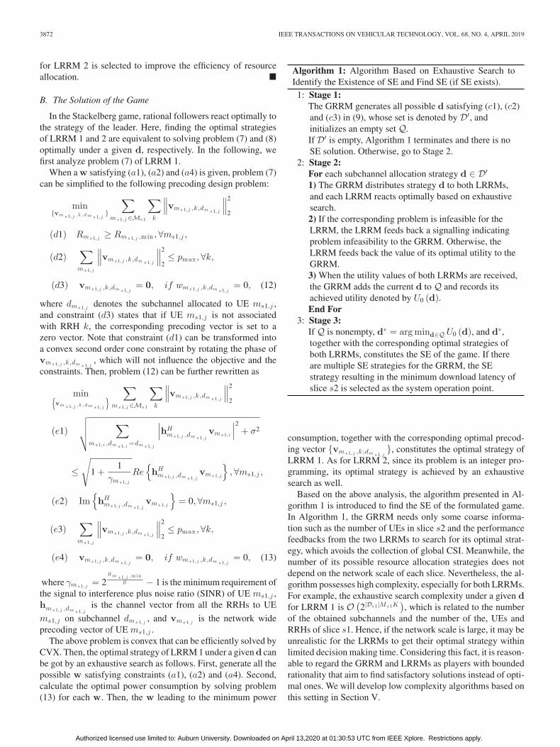
1: Stage 1:The GRRM generates all possible d satisfying (c1), (c2)and (c3) in (9), whose set is denoted by D′, andinitializes an empty set Q.If D′ is empty, Algorithm 1 terminates and there is noSE solution. Otherwise, go to Stage 2.
2: Stage 2:For each subchannel allocation strategy d ∈ D′1) The GRRM distributes strategy d to both LRRMs,and each LRRM reacts optimally based on exhaustivesearch.2) If the corresponding problem is infeasible for theLRRM, the LRRM feeds back a signalling indicatingproblem infeasibility to the GRRM. Otherwise, theLRRM feeds back the value of its optimal utility to theGRRM.3) When the utility values of both LRRMs are received,the GRRM adds the current d to Q and records itsachieved utility denoted by U0 (d).End For
3: Stage 3:If Q is nonempty, d∗ = arg mind∈Q U0 (d), and d∗,together with the corresponding optimal strategies ofboth LRRMs, constitutes the SE of the game. If thereare multiple SE strategies for the GRRM, the SEstrategy resulting in the minimum download latency ofslice s2 is selected as the system operation point.
consumption, together with the corresponding optimal precod-ing vector {vms 1, j ,k ,dm s 1, j
}, constitutes the optimal strategy ofLRRM 1. As for LRRM 2, since its problem is an integer pro-gramming, its optimal strategy is achieved by an exhaustivesearch as well.
Based on the above analysis, the algorithm presented in Al-gorithm 1 is introduced to find the SE of the formulated game.In Algorithm 1, the GRRM needs only some coarse informa-tion such as the number of UEs in slice s2 and the performancefeedbacks from the two LRRMs to search for its optimal strat-egy, which avoids the collection of global CSI. Meanwhile, thenumber of its possible resource allocation strategies does notdepend on the network scale of each slice. Nevertheless, the al-gorithm possesses high complexity, especially for both LRRMs.For example, the exhaustive search complexity under a given dfor LRRM 1 is O (2|Ds 1|Ms 1K
), which is related to the number
of the obtained subchannels and the number of the, UEs andRRHs of slice s1. Hence, if the network scale is large, it may beunrealistic for the LRRMs to get their optimal strategy withinlimited decision making time. Considering this fact, it is reason-able to regard the GRRM and LRRMs as players with boundedrationality that aim to find satisfactory solutions instead of opti-mal ones. We will develop low complexity algorithms based onthis setting in Section V.
Authorized licensed use limited to: Auburn University. Downloaded on April 13,2020 at 01:30:53 UTC from IEEE Xplore. Restrictions apply.
SUN et al.: HIERARCHICAL RADIO RESOURCE ALLOCATION FOR NETWORK SLICING IN FOG RADIO ACCESS NETWORKS 3873
V. LOW COMPLEXITY ALGORITHM DESIGN FOR
GAME PLAYERS
In this section, low complexity algorithms are developed forthe GRRM and LRRMs to help them achieve local optimalsolutions when they behave as players with bounded rationalitywho intend to find satisfactory solutions within limited time fordecision making.
A. Low Complexity Algorithm Design for LRRM 1
From problem (7), it can be seen that the main complexity liesin the optimization of wms 1, j ,k ,d representing RRH associationand subchannel allocation. Note that subchannel allocation isactually equivalent to identifying the subchannel sharing rela-tionship among UEs, which can be considered from a coalitionalgame perspective. Specifically, each subchannel can correspondto a coalition, and the UE joining a certain coalition occupiesthe corresponding subchannel. A low complexity and effectiveapproach to form a stable coalitional structure is to make UEstraverse coalitions based on the transfer order [41], and the defi-nition of the order depends on the system optimization objective.Since LRRM 1 aims at minimizing system transmit power con-sumption, it is assumed that a UE transfers from a coalition toanother coalition if and only if the overall power consumptionstrictly decreases.
When the subchannel allocation is fixed, the remaining taskis to design a low complexity scheme to jointly optimize theUE-RRH association and precoding. To facilitate theoreticalanalysis, we define a UE-RRH association matrix E whose(j, k)-th element ems 1, j ,k is a 0-1 variable, which equals to 1if UE ms1,j associates with RRH k and equals to 0 otherwise.Then, the problem of LRRM 1 under fixed subchannel allocationis given by
min{vm s 1, j , k , d m s 1, j
}{em s 1, j , k }∑
ms 1, j ∈Ms 1
∑
k
∥∥∥vms 1, j ,k ,dm s 1, j
∥∥∥2
2
(f1)
√√√√∑
ms 1, i ,dm s 1, i=dm s 1, j
∣∣∣hHms 1, j ,dm s 1, j
vms 1, i
∣∣∣2+ σ2
≤√
1 +1
γms 1, j
Re{hH
ms 1, j ,dm s 1, jvms 1, j
},∀ms1,j ,
(f2) Im{hH
ms 1, j ,dm s 1, jvms 1, j
}= 0,∀ms1,j ,
(f3)∑
ms 1, j
∥∥∥vms 1, j ,k ,dm s 1, j
∥∥∥2
2≤ pmax ,∀k,
(f4)∑
ms 1, j
ems 1, j ,k ≤ ok , ∀k,
(f5) vms 1, j ,k ,dm s 1, j= 0, if ems 1, j ,k = 0,
(f6) ems 1, j ,k ∈ {0, 1} . (14)
Algorithm 2: Resource Allocation Under Pre-DeterminedSubchannel Allocation for LRRM 1.
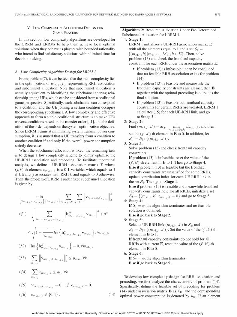
1: Stage 1:LRRM 1 initializes a UE-RRH association matrix Ewith all the elements equal to 1 and a set S1 ={(ms1,j , k) |ms1,j ∈Ms1, k ∈ K}. Then, solveproblem (13) and check the fronthaul capacityconstraint for each RRH under the association matrix E.
� If problem (13) is infeasible, it can be concludedthat no feasible RRH association exists for problem(14).
� If problem (13) is feasible and meanwhile thefronthaul capacity constraints are all met, then Etogether with the optimal precoding is output as thefinal solution.
� If problem (13) is feasible but fronthaul capacityconstraints for certain RRHs are violated, LRRM 1calculates (15) for each UE-RRH link, and goto Stage 2.
2: Stage 2:Find (ms1,j ′ , k
′) = arg min(ms 1, j ,k)∈S1
βms 1, j ,k , and then
set the (j′, k′)-th element in E to 0. In addition, letS1 ← S1/ {(ms1,j ′ , k
′)}.3: Stage 3:
Solve problem (13) and check fronthaul capacityconstraints.If problem (13) is infeasible, reset the value of the(j′, k′)-th element in E to 1. Then go to Stage 4.Else if problem (13) is feasible but the fronthaulcapacity constraints are unsatisfied for some RRHs,update contribution index for each UE-RRH link inthe set S1. Then go to Stage 4.Else if problem (13) is feasible and meanwhile fronthaulcapacity constraints hold for all RRHs, initialize a setS2 =
{(ms1,j , k) |ems 1, j ,k = 0
}and go to Stage 5.
4: Stage 4:If S1 = φ, the algorithm terminates and no feasiblesolution is obtained.Else if go back to Stage 2.
5: Stage 5:Select a UE-RRH link (ms1,j ′ , k
′) in S2, andS2 ← S2/ {(ms1,j ′ , k
′)}. Set the value of the (j′, k′)-thelement in E to 1.If fronthaul capacity constraints do not hold for allRRHs with current E, reset the value of the (j′, k′)-thelement in E to 0.
6: Stage 6:If S2 = φ, the algorithm terminates.Else if go back to Stage 5.
To develop low complexity design for RRH association andprecoding, we first analyze the characteristic of problem (14).Specifically, define the feasible set of precoding for problem(14) under association matrix E as VE , and the correspondingoptimal power consumption is denoted by u∗E . If an element
Authorized licensed use limited to: Auburn University. Downloaded on April 13,2020 at 01:30:53 UTC from IEEE Xplore. Restrictions apply.
3874 IEEE TRANSACTIONS ON VEHICULAR TECHNOLOGY, VOL. 68, NO. 4, APRIL 2019
ems 1, j ,k = 1 in E is set to 0 and the new association matrix isdenoted as E−, we have VE− ⊆ VE and hence u∗E ≤ u∗E− . Thismeans more active UE-RRH links can contribute to a betterslice performance, which motivates us to introduce Algorithm 2to have as many active links as possible meanwhile keepingthe feasibility of constraint (f4) of problem (14). The wholealgorithm is mainly composed of two parts. The first part startswith activating all UE-RRH links and gradually drops off weaklinks to satisfy fronthaul capacity constraints including Stage1-Stage 4, while the second part, including Stage 5-Stage 6,tries to reactivate links dropped off in the first part. The metricto identify weak links, which is called contribution index in thefollowing, is given by
βms 1, j ,k=|hH
ms 1, j ,k ,dm s 1, jvms 1, j ,k ,dm s 1, j
|2∣∣∣∑
k ′∈K hHms 1, j ,k ′,dm s 1, j
vms 1, j ,k ′,dm s 1, j
∣∣∣2 , (15)
which shows the contribution of RRH k on the received signalstrength of UE ms1,j . It should be highlighted that problem (14)is reduced to problem (13) under fixed UE-RRH association.Therefore, under a fixed association matrix meeting fronthaulcapacity constraints (f4) in (14), checking the feasibility ofproblem (14) is equivalent to checking the feasibility of problem(13). In other words, problem (14) is feasible if and only if theassociation matrix satisfies fronthaul capacity constraints andmeanwhile problem (13) is also feasible under this associationmatrix. Based on this finding, Stage 3 in Algorithm 2 is designed,which checks both the violation of fronthaul capacity constraintsand the feasibility of problem (13).
Note that the number of possible UE-RRH links checkedin Algorithm 2 is at most 2Ms1K. Since each checkmay include a precoding optimization whose complexity isO((KMs1)
3.5N 3.5), the total complexity of Algorithm 2 isO((KMs1)
4.5N 3.5). After the algorithm terminates, the RRHassociation outcome is a local optimal solution to problem (14),and rigorous proof is as follows.
Theorem 2: The final outcome achieved by Algorithm 2 is alocal optimal solution to problem (14) in the sense that activatingor inactivating any RRH-UE link can not further improve theslice performance while keeping all the constraints satisfied.
Proof: Denote the final association matrix output by Algo-rithm 2 as E which must be feasible to problem (14). As dis-cussed above, inactivating a link in E can not contribute to alower transmit power consumption due to a smaller feasible setof precoding for problem (13). Next, we prove that activatinga link in E can not further improve slice performance as well.First, if E is a matrix with all elements equal to 1, it is obviousthat no link can be activated, and hence E must be local optimal.
Then, we discuss the case where there exists at least one zeroelement in E. Assume that there exists another association ma-trix E+ that is got based on E by activating a UE-RRH link(ms1,j , k) that has been dropped off, and meanwhile meets thefronthaul capacity constraints for all RRHs. Define the set ofactive links in association matrix E as SE
active , and then we haveSE
active ⊂ SE+
active . According to Algorithm 2, the UE-RRH link(ms1,j , k) must be checked in Stage 5, and we denote the corre-
Algorithm 3: Resource Allocation Algorithm Based onTransfer Order for LRRM 1.
1: Stage 1:LRRM 1 initializes a coalitional structure Πini ={π1, π2, ..., π|Ds 1|
}with πd ⊆Ms1, π1 ∪ π2 · · · ∪
π|Ds 1| =Ms1, and πd ∩ πd ′ = φ, ∀d �= d′. Denotethe index of the coalition to which UE ms1,j belongs asdms 1, j
∈ {1, 2, ..., |Ds1|}. Compute U1 (Πini) bysolving the RRH association and precodingoptimization problem (14) using Algorithm 2.
2: Stage 2:For j = 1 : Ms1
For d = 1 : |Ds1|If d �= dms 1, j
Πcurrent = Πini/{
πd, πdm s 1, j
}∪
{πd ∪ {ms1,j} , πdm s 1, j
/ {ms1,j}}
. Compute
U1 (Πcurrent) using Algorithm 2.If U1 (Πini) > U1 (Πcurrent) (transfer condition)
Πini ← Πcurrent and dms 1, j← d.
End IfEnd If
End ForEnd For
3: Stage 3:Repeat Stage 2 until the coalitional structure Πini
converges.
sponding association matrix as E′. From the algorithm, it can beknown that E′ does not satisfy fronthaul capacity constraints forall RRHs, because the UE-RRH link (ms1,j , k) will be activatedin E otherwise. But on the other hand, since SE ′
active ⊆ SEactive
and SEactive ⊂ SE+
active , we have SE ′active ⊂ SE+
active , and henceSE ′
active must satisfy all the fronthaul constraints as well, whichmakes a contradiction. Thus, activating any inactive link in Emust lead to an association matrix violating fronthaul capacityconstraints. Finally, we can conclude that the outcome achievedby Algorithm 2 must be local optimal.
Finally, an iterative algorithm based on coalitional game withtransfer order is proposed for LRRM 1, which is described in Al-gorithm 3. Since the number of available subchannels and UEsis limited, the number of possible subchannel allocation resultsis limited, and thus the number of possible coalitional structuresis limited. Note that each successful transfer guarantees thatthe transmit power of slice s1 strictly decreases, which resultsin a totally new coalitional structure. Therefore, the algorithmfinally converges after a finite number of iterations. Moreover,according to the algorithm, its convergence indicates a stablesolution to the subchannel allocation in the sense that the systemtransmit power cannot be strictly decreased by changing anyUE’s subchannel allocation unilaterally. Considering Theorem2, the resource allocation outcome resulting from Algorithm3 can be claimed to be local optimal. Specifically, keepingRRH association and precoding fixed, changing any UE’ssubchannel allocation can not improve the slice performance,
Authorized licensed use limited to: Auburn University. Downloaded on April 13,2020 at 01:30:53 UTC from IEEE Xplore. Restrictions apply.
SUN et al.: HIERARCHICAL RADIO RESOURCE ALLOCATION FOR NETWORK SLICING IN FOG RADIO ACCESS NETWORKS 3875
while activating or dropping off any UE-RRH link can notimprove the slice performance as well when keeping thesubchannel allocation fixed. Finally, the total complexity for theabove algorithm in each iteration isO (|Ds1|Ms1
5.5K4.5N 3.5).
B. Low Complexity Algorithm Design for LRRM 2
The optimization problem (8) of LRRM 2 is actually a match-ing problem between UEs and resources, which motivates theadoption of matching theory to develop a low complexity algo-rithm. According to the constraints in (8), each UE can be allo-cated with only one subchannel-FAP pair and each subchannel-FAP pair can serve only one UE. Hence, a one-to-one matchingproblem between UEs and subchannel-FAP pairs can be for-mulated. Define the set of all the subchannel-FAP pairs as Awith |A| = |Ds2|L. Then, the concerned matching problem isformally defined as follows.
Definition 2: A matching μ is a one-to-one mapping betweenUEs and subchannel-FAP pairs satisfying
1. If μ (ms2,j ) = a, then μ (a) = ms2,j , ∀ms2,j ∈Ms2 and∀a ∈ A, and vice versa.
2. |μ (ms2,j )| = 1,∀ms2,j ∈Ms2.3. |μ (a)| ≤ 1,∀a ∈ A.The first condition states that a matching establishes a mu-
tual relationship between the elements in two different sets.The second condition requires that each UE must be mappedto a subchannel-FAP pair, otherwise the average download la-tency will be infinite. The third condition guarantees that eachsubchannel-FAP pair can serve at most one UE. Moreover, thedownload latency of each UE calculated by (6) depends on notonly its own matching to subchannel-FAP pairs but also thematching between other UEs and subchannel-FAP pairs, whichcauses externality of the formulated matching problem. Hence,the classic deferred acceptance algorithm cannot be applied [44].Meanwhile, there is no guarantee on the existence of a pair-wisestable matching [45]. Therefore, the concept of swap matching isincorporated to effectively tackle the matching problem, whosedefinition is given as follows.
Definition 3: Assume that under matching μ,μ (ms2,j ) = a and μ (ms2,j ′) = a′. Then, μa,a ′
ms 2, j ,m s 2, j ′ =μ/ {(ms2,j , a) , (ms2,j ′ , a
′)} ∪ {(ms2,j , a′) , (ms2,j ′ , a)} is a
swap matching.It should be highlighted that one of the UEs involved in the
swap can be a dummy UE, which means that no UE is servedby the subchannel-FAP pair it matches with, and a UE can bemapped to this pair directly. However, considering that an FAPcan serve only finite number of UEs, there is a special case forthe definition of swap matching. Specifically, suppose that a UEms2,j with μ (ms2,j ) = a intends to swap to a subchannel-FAPpair a′ not occupied by any UE, and the FAP in pair a′ does notassociate with UE ms2,j currently. If the quota of the FAP hasbeen full, i.e., the constraint (b3) in problem (8) takes equality,to keep the feasibility of the resource allocation solution, a UEms2,j ′′ served by the FAP should be switched to the subchannel-FAP pair a when UE ms2,j swaps to subchannel-FAP pair a′.
Algorithm 4: Resource Allocation Algorithm Based onSwap Matching for LRRM 2.
1: Stage 1:LRRM 2 generates the set of all possible subchannel-FAP pairs A and initializes a feasible UE-resourcematching μ satisfying constraints in problem (8).Denote the i-th subchannel-FAP pair in set A as ai .
2: Stage 2:For j = 1 : Ms2
For i = 1 : |A|If μ (ms2,j ) �= ai
Check whether μa,ai
ms 2, j ,μ(ai )is preferred according
to the swap condition. Especially, when UE ms2,j is notassociated with the FAP included in subchannel-FAPpair ai not matched to any UE, and meanwhile the quotaof the FAP has been achieved, one of the q UEs servedby the FAP should be swaped to the subchannel-FAPpair currently matched to UE ms2,j to keep a feasiblematching.
If Swap condition holdsμ← μa,ai
ms 2, j ,μ(ai ).
End IfEnd IfEnd ForEnd For
3: Stage 3:Repeat Stage 2 until the UE-resource matching μconverges.
Since the LRRM aims to minimize the average down-load latency of UEs, the swap condition is defined asfollows.
Definition 4: (Swap Condition) Denote the subchannelsincluded in subchannel-FAP pair a and a′ by da and da ′ ,respectively, and define Dswap = {da} ∪ {da ′ }. Then, a swapmatching μa,a ′
ms 2, j ,m s 2, j ′ is preferred by LRRM 2 to the currentmatching μ if
∑
ms 2, j ,dμ (m s 2, j )∈Ds w a p
tms 2, j(μa,a ′
ms 2, j ,m s 2, j ′ )
<∑
ms 2, j ,dμ (m s 2, j )∈Ds w a p
tms 2, j(μ). (16)
Note that the download latency for UE ms2,j is expressedas a function of the current matching due to the existence ofexternality. For the special case of swap matching discussedbefore, denote the subchannel allocated to UE ms2,j ′′ by da ′′ ,and then the set of subchannels related to the swap is now givenby Dswap = {da} ∪ {da ′ } ∪ {da ′′ }.
Based on the above definitions, a low complexity resourceallocation algorithm for LRRM 2 is presented in Algorithm 4.From the swap condition, it can be seen that each swap opera-tion leads to a strict decrease of the system average downloadlatency, and hence a completely new matching will be generated
Authorized licensed use limited to: Auburn University. Downloaded on April 13,2020 at 01:30:53 UTC from IEEE Xplore. Restrictions apply.
3876 IEEE TRANSACTIONS ON VEHICULAR TECHNOLOGY, VOL. 68, NO. 4, APRIL 2019
Algorithm 5: Resource Allocation Algorithm Based onSwap Operations for the GRRM.
1: Stage 1:Initially, the GRRM allocates one subchannel to slices2, while the remaining subchannels are allocated toslice s1. After being informed about the resourceallocation result, LRRM 1 and LRRM 2 perform localresource optimization, and then report sliceperformance to the GRRM, based on which the GRRMidentifies its initial utility U0 according to (9).
2: Stage 2:For subchannel d = 1 : D:For slice i = s1 : s2:For subchannel di ∈ Di :
The GRRM tries the first kind of swap operationsinvolving subchannel d and di , and notifies the LRRMsof slices about the subchannel allocation.
LRRM 1 and LRRM 2 do resource optimization,and then feed back slice performance to the GRRM.
If the swap operation condition holds:Update subchannel allocation between slices and
go back to the second For loop.End If
End forIf no update of subchannel allocation between slices
occurs:Try the second kind of swap operations, and notify
the LRRMs of slices about the subchannel allocation.LRRM 1 and LRRM 2 do resource optimization,
and then feed back slice performances to the GRRM.If the swap operation condition holds:
Update subchannel allocation between slicesand go back to the second For loop.
End IfEnd If
End ForEnd For
3: Stage 3:Repeat Stage 2 until the subchannel allocation betweenslices converges.
after each swap. Because of the limited number of all possibleUE-resource matchings, the algorithm will converge to a finalmatching after finite iterations. Moreover, the convergence of thematching means a local optimal resource allocation outcome inthe sense that any swap will not improve the latency perfor-mance of slice s2. The complexity of the algorithm for eachiteration is O (Ms2 |Ds2|Lq), where q is the maximal numberof UEs that can be served by an FAP.
C. Low Complexity Algorithm Design for the GRRM
In this subsection, a low complexity algorithm will be de-veloped for the GRRM to avoid the exhaustive complexity, andhence good scalability can be achieved when the number of sub-channels is very large. Specifically, a concept similar to swapmatching is defined as follows.
Definition 5: (Resource Swap Operation) Define the firstkind of swap operations of the GRRM as Ds1/ {ds1} ∪ {ds2}and Ds2/ {ds2} ∪ {ds1}, where ds1 ∈ Ds1 and ds2 ∈ Ds2, anddefine the second kind of swap operations of the GRRM asDs1 ∪ {ds2} with Ds2/ {ds2} or Ds2 ∪ {ds1} with Ds1/ {ds1}.
Then, the following condition is given to identify whether toexecute swap operations.
Definition 6: (Swap Operation Condition) A swap operationis performed if and only if the utility of the GRRM U0 is strictlydecreased.
Based on these definitions, our proposed low complexityresource allocation scheme for the GRRM is elaborated inAlgorithm 5. According to the swap operation condition, eachupdate of subchannel allocation between slices means a strictimprovement on the utility of the GRRM U0. Since radio re-sources are limited, there is a lower bound of U0. Hence, afterfinite subchannel allocation updates, Algorithm 5 will convergeto a final resource allocation strategy. In addition, the strategyis local optimal in the sense that no swap operations can furtherimprove the utility of the GRRM. The complexity of the algo-rithm in each iteration is O (D2
), showing a good scalability
when the number of subchannels is large. Note that Algorithm5 can be adopted to allocate any type of resources between twoslices with any performance metrics. For example, each sub-channel in this algorithm can be replaced by a resource bundleincluding radio resources, caching resources and computing re-sources. Moreover, once the GRRM reaches its local optimalstrategy by Algorithm 5, it has no incentive to change the strat-egy according to the assumption of bounded rationality. Then,after each LRRM plays its local optimal strategy given the strat-egy of the GRRM, a weak version of SE is reached followingthe definition of SE.
VI. SIMULATION RESULTS AND ANALYSIS
In all the simulations, the bandwidth of each subchannel is180kHz, and the channel coefficient of each link is composed ofpath loss and fast fading. The pathloss model is d−2 with d beingthe distance between the two nodes in the same link. The fastfading is modeled as an independent complex Gaussian randomvariable distributed as CN(0, 1). The maximal transmit power ofeach RRH is 1.5 W, and the number of antennas in each RRH is2. The noise power is set to 10−13 W, and the SINR requirementof UEs in slice s1 is taken as 5 dB. The transmit power ofeach FAP over each subchannel is 125 mW, and each FAP canserve at most 5 UEs. In addition, it is assumed that the contentsrequested by UEs in slice s2 are available at the caches of allFAPs with the size of each content set to 10Mbits. Consideringthe randomness of user content requests, the assumption for100% cache hit rate under a specific realization of user contentrequests is reasonable. However, note that our proposed resourceallocation algorithms for slice s2 can fit into any cache hitsituation.
A. Achieving SE via Exhaustive Search
The simulation scenario in this part consists of two F-RANslices shown in Fig. 2, where the axis unit is in meters. Mean-
Authorized licensed use limited to: Auburn University. Downloaded on April 13,2020 at 01:30:53 UTC from IEEE Xplore. Restrictions apply.
SUN et al.: HIERARCHICAL RADIO RESOURCE ALLOCATION FOR NETWORK SLICING IN FOG RADIO ACCESS NETWORKS 3877
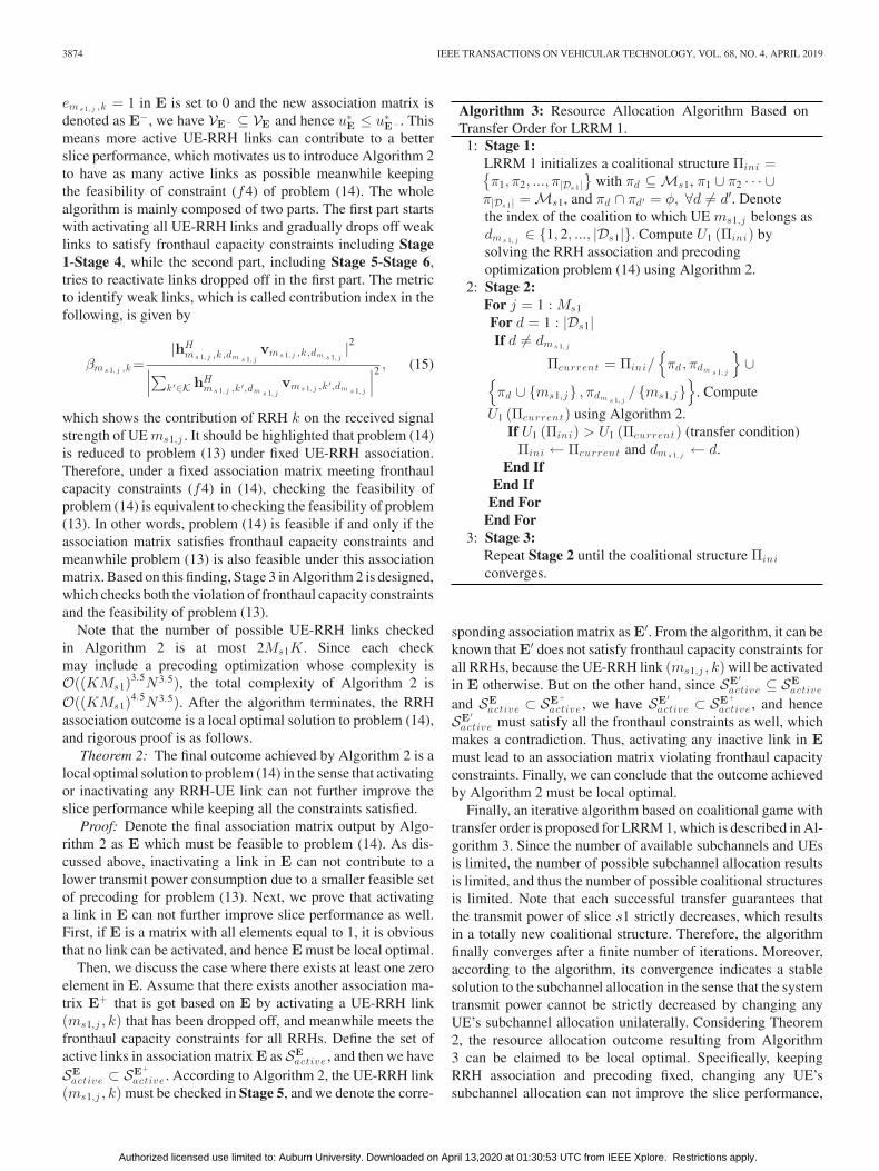
Fig. 2. Simulation scenario.
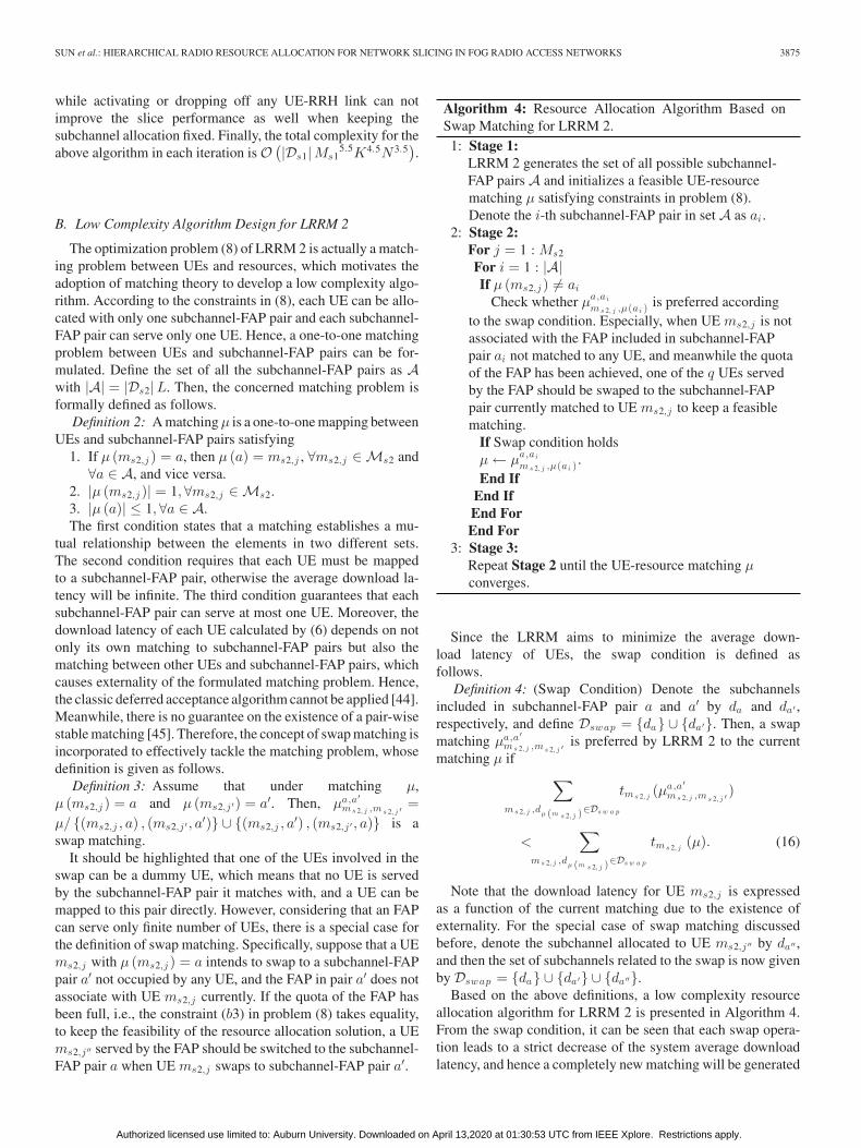
Fig. 3. The utility evolution of the GRRM.
while, we suggest that five subchannels are to be allocated by theGRRM, and each fronthaul link can support at most two UEs.Note that the reason for adopting such a small scale topology inFig. 2 is to facilitate the calculation of SE by exhaustive search.
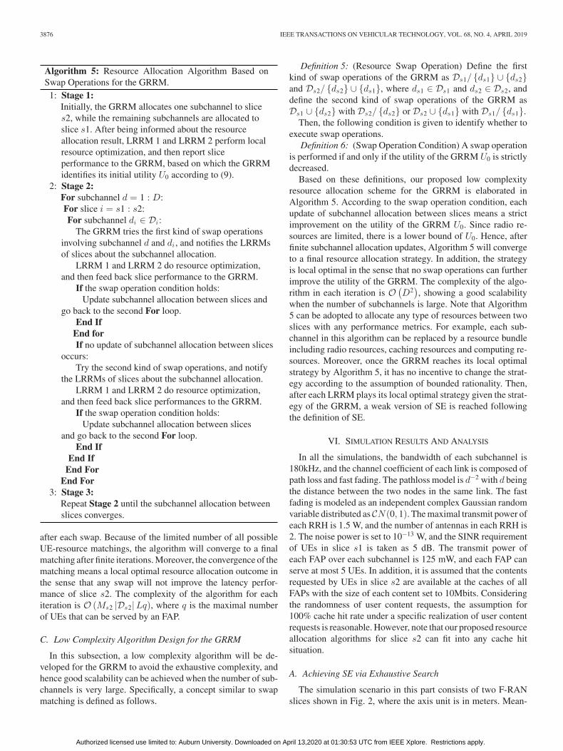
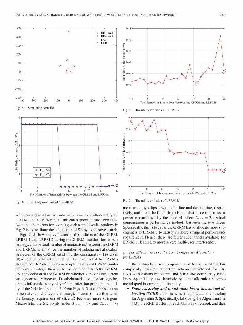
Figs. 3–5 show the evolution of the utilities of the GRRM,LRRM 1 and LRRM 2 during the GRRM searches for its beststrategy, and the total number of interactions between the GRRMand LRRMs is 25, since the number of subchannel allocationstrategies of the GRRM satisfying the constraints (c1)-(c3) in(9) is 25. Each interaction includes the broadcast of the GRRM’sstrategy to LRRMs, the resource optimization of LRRMs underthat given strategy, their performance feedback to the GRRM,and the decision of the GRRM on whether to record the currentstrategy or not. Moreover, if a subchannel allocation strategy be-comes infeasible to any player’s optimization problem, the util-ity of the GRRM is set to 4.5. From Figs. 3–5, it can be seen thatmore subchannel allocation strategies become infeasible whenthe latency requirement of slice s2 becomes more stringent.Meanwhile, the SE points under Tmax = 3s and Tmax = 7s
Fig. 4. The utility evolution of LRRM 1.
Fig. 5. The utility evolution of LRRM 2.
are marked by ellipses with solid line and dashed line, respec-tively, and it can be found from Fig. 4 that more transmissionpower is consumed by the slice s1 when Tmax = 3s, whichdemonstrates a performance tradeoff between the two slices.Specifically, this is because the GRRM has to allocate more sub-channels to LRRM 2 to satisfy its more stringent performancerequirement. Hence, there are fewer subchannels available forLRRM 1, leading to more severe multi-user interference.
B. The Effectiveness of the Low Complexity Algorithmsfor LRRMs
In this subsection, we compare the performance of the lowcomplexity resource allocation schemes developed for LR-RMs with exhaustive search and other low complexity base-lines. Specifically, two heuristic resource allocation schemesare adopted in our simulation study:
� Static clustering and round-robin based subchannel al-location (SCRR): This scheme is adopted as the baselinefor Algorithm 3. Specifically, following the Algorithm 3 in[43], the RRH cluster for each UE is first formed, and then
Authorized licensed use limited to: Auburn University. Downloaded on April 13,2020 at 01:30:53 UTC from IEEE Xplore. Restrictions apply.
3878 IEEE TRANSACTIONS ON VEHICULAR TECHNOLOGY, VOL. 68, NO. 4, APRIL 2019
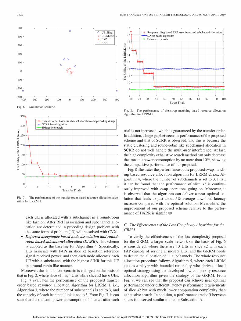
Fig. 6. Simulation scenario.
Fig. 7. The performance of the transfer order based resource allocation algo-rithm for LRRM 1.
each UE is allocated with a subchannel in a round-robinlike fashion. After RRH association and subchannel allo-cation are determined, a precoding design problem withthe same form of problem (13) will be solved with CVX.
� Deferred acceptance based node association and round-robin based subchannel allocation (DARR): This schemeis adopted as the baseline for Algorithm 4. Specifically,UEs associate with FAPs in slice s2 based on referencesignal received power, and then each node allocates eachUE with a subchannel with the highest SINR for this UEin a round-robin like manner.
Moreover, the simulation scenario is enlarged on the basis ofthat in Fig. 2, where slice s1 has 4 UEs while slice s2 has 6 UEs.
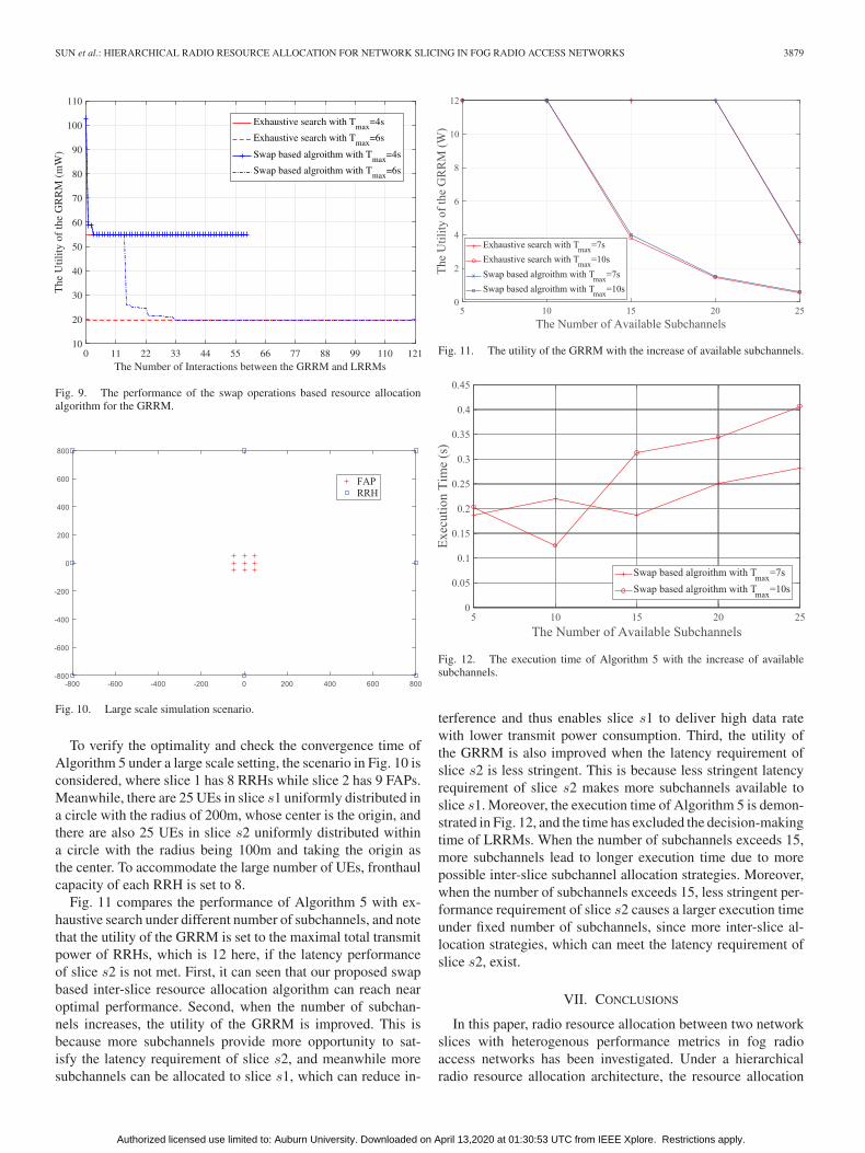
Fig. 7 evaluates the performance of the proposed transferorder based resource allocation algorithm for LRRM 1, i.e.,Algorithm 3, where the number of subchannels is set to 3, andthe capacity of each fronthaul link is set to 3. From Fig. 7, it canseen that the transmit power consumption of slice s1 after each
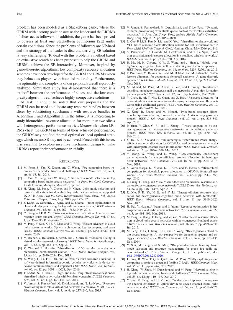
Fig. 8. The performance of the swap matching based resource allocationalgorithm for LRRM 2.
trial is not increased, which is guaranteed by the transfer order.In addition, a huge gap between the performance of the proposedscheme and that of SCRR is observed, and this is because thestatic clustering and round-robin like subchannel allocation inSCRR do not well handle the multi-user interference. At last,the high complexity exhaustive search method can only decreasethe transmit power consumption by no more than 10%, showingthe competitive performance of our proposal.
Fig. 8 illustrates the performance of the proposed swap match-ing based resource allocation algorithm for LRRM 2, i.e., Al-gorithm 4, where the number of subchannels is set to 3. First,it can be found that the performance of slice s2 is continu-ously improved with swap operations going on. Moreover, itis observed that the algorithm can deliver a near optimal so-lution that leads to just about 5% average download latencyincrease compared with the optimal solution. Meanwhile, theimprovement of our proposed scheme relative to the perfor-mance of DARR is significant.
C. The Effectiveness of the Low Complexity Algorithm for theGRRM
To verify the effectiveness of the low complexity proposalfor the GRRM, a larger scale network on the basis of Fig. 6is considered, where there are 13 UEs in slice s2 with eachFAP capable of serving at most 5 UEs, and the GRRM needsto decide the allocation of 11 subchannels. The whole resourceallocation procedure follows Algorithm 5, where each LRRMacts as a player with bounded rationality who derives a localoptimal strategy using the developed low complexity resourceallocation algorithm given the strategy of the GRRM. FromFig. 9, we can see that the proposal can achieve near optimalperformance under different latency performance requirementsof slice s2 but with much lower computation complexity thanexhaustive search. In addition, a performance tradeoff betweenslices is observed similar to that in Subsection A.
Authorized licensed use limited to: Auburn University. Downloaded on April 13,2020 at 01:30:53 UTC from IEEE Xplore. Restrictions apply.
SUN et al.: HIERARCHICAL RADIO RESOURCE ALLOCATION FOR NETWORK SLICING IN FOG RADIO ACCESS NETWORKS 3879
Fig. 9. The performance of the swap operations based resource allocationalgorithm for the GRRM.
Fig. 10. Large scale simulation scenario.
To verify the optimality and check the convergence time ofAlgorithm 5 under a large scale setting, the scenario in Fig. 10 isconsidered, where slice 1 has 8 RRHs while slice 2 has 9 FAPs.Meanwhile, there are 25 UEs in slice s1 uniformly distributed ina circle with the radius of 200m, whose center is the origin, andthere are also 25 UEs in slice s2 uniformly distributed withina circle with the radius being 100m and taking the origin asthe center. To accommodate the large number of UEs, fronthaulcapacity of each RRH is set to 8.
Fig. 11 compares the performance of Algorithm 5 with ex-haustive search under different number of subchannels, and notethat the utility of the GRRM is set to the maximal total transmitpower of RRHs, which is 12 here, if the latency performanceof slice s2 is not met. First, it can seen that our proposed swapbased inter-slice resource allocation algorithm can reach nearoptimal performance. Second, when the number of subchan-nels increases, the utility of the GRRM is improved. This isbecause more subchannels provide more opportunity to sat-isfy the latency requirement of slice s2, and meanwhile moresubchannels can be allocated to slice s1, which can reduce in-
Fig. 11. The utility of the GRRM with the increase of available subchannels.
Fig. 12. The execution time of Algorithm 5 with the increase of availablesubchannels.
terference and thus enables slice s1 to deliver high data ratewith lower transmit power consumption. Third, the utility ofthe GRRM is also improved when the latency requirement ofslice s2 is less stringent. This is because less stringent latencyrequirement of slice s2 makes more subchannels available toslice s1. Moreover, the execution time of Algorithm 5 is demon-strated in Fig. 12, and the time has excluded the decision-makingtime of LRRMs. When the number of subchannels exceeds 15,more subchannels lead to longer execution time due to morepossible inter-slice subchannel allocation strategies. Moreover,when the number of subchannels exceeds 15, less stringent per-formance requirement of slice s2 causes a larger execution timeunder fixed number of subchannels, since more inter-slice al-location strategies, which can meet the latency requirement ofslice s2, exist.
VII. CONCLUSIONS
In this paper, radio resource allocation between two networkslices with heterogenous performance metrics in fog radioaccess networks has been investigated. Under a hierarchicalradio resource allocation architecture, the resource allocation
Authorized licensed use limited to: Auburn University. Downloaded on April 13,2020 at 01:30:53 UTC from IEEE Xplore. Restrictions apply.
3880 IEEE TRANSACTIONS ON VEHICULAR TECHNOLOGY, VOL. 68, NO. 4, APRIL 2019
problem has been modeled as a Stackelberg game, where theGRRM with a strong position acts as the leader and the LRRMsof slices act as followers. In addition, the game has been provedto possess at least one Stackelberg equilibrium (SE) undercertain conditions. Since the problems of followers are NP-hardand the strategy of the leader is discrete, deriving SE solutionis very challenging. To deal with this problem, a method basedon exhaustive search has been proposed to help the GRRM andLRRMs achieve the SE interactively. Moreover, inspired bygame-theoretic algorithms, low complexity resource allocationschemes have been developed for the GRRM and LRRMs whenthey behave as players with bounded rationality. Furthermore,the optimality and complexity of our proposals are all rigorouslyanalyzed. Simulation study has demonstrated that there is atradeoff between the performance of slices, and the low com-plexity algorithms can achieve highly competitive solutions.
At last, it should be noted that our proposals for theGRRM can be used to allocate any resource bundles betweenslices by substituting subchannels with resource bundles inAlgorithm 1 and Algorithm 5. In the future, it is interesting tostudy hierarchical resource allocation for more than two sliceswith heterogenous performance metrics. Meanwhile, when LR-RMs cheat the GRRM in terms of their achieved performance,the GRRM may not find the real optimal or local optimal strat-egy, which means SE may not be achieved. Faced with this issue,it is essential to explore incentive mechanism design to makeLRRMs report their performance truthfully.
REFERENCES
[1] M. Peng, S. Yan, K. Zhang, and C. Wang, “Fog computing based ra-dio access networks: Issues and challenges,” IEEE Netw., vol. 30, no. 4,pp. 46–53, Jul. 2016.
[2] S. Yan, M. Peng, and W. Wang, “User access mode selection in fogcomputing based radio access networks,” in Proc. Int. Conf. Commun.,Kuala Lumpur, Malaysia, May 2016, pp. 1–6.
[3] H. Xiang, M. Peng, Y. Cheng, and H. Chen, “Joint mode selection andresource allocation for downlink fog radio access networks supportedD2D,” in Proc. 11th Int. Conf. Heterogeneous Netw. Qual., Rel., Secur.Robustness, Taipei, China, Aug. 2015, pp. 177–182.
[4] J. Kang, O. Simeone, J. Kang, and S. Shamai, “Joint optimization ofcloud and edge processing for fog radio access networks,” IEEE WirelessCommun., vol. 15, no. 11, pp. 7621–7632, Nov. 2016.
[5] C. Liang and F. R. Yu, “Wireless network virtualization: A survey, someresearch issues and challenges,” IEEE Commun. Surveys Tut., vol. 17, no.1, pp. 358–380, First quarter 2015.
[6] M. Peng, Y. Sun, X. Li, Z. Mao, and C. Wang, “Recent advances in cloudradio access networks: System architectures, key techniques, and openissues,” IEEE Commun. Surveys Tut., vol. 18, no. 3, pp. 2282–2308, Thirdquarter 2016.
[7] M. Richart, J. Baliosian, J. Serrat, and J. Gorricho, “Resource slicing invirtual wireless networks: A survey,” IEEE Trans. Netw. Service Manage.,vol. 13, no. 3, pp. 462–476, Sep. 2016.
[8] K. Zhu and E. Hossain, “Virtualization of 5G cellular networks as ahierarchical combinatorial auction,” IEEE Trans. Mobile Comput., vol.15, no. 10, pp. 2640–2654, Dec. 2015.
[9] K. Wang, H. Li, F. R. Yu, and W. Wei, “Virtual resource allocation insoftware-defined information-centric cellular networks with device-to-device communications and imperfect CSI,” IEEE Trans. Veh. Technol.,vol. 65, no. 12, pp. 10011–10021, Dec. 2016.
[10] T. LeAnh, N. H. Tran, D. T. Ngo, and C. S. Hong, “Resource allocation forvirtualized wireless networks with backhaul constraints,” IEEE Commun.Lett., vol. 21, no. 1, pp. 148–151, Jan. 2017.
[11] V. Jumba, S. Parsaeefard, M. Derakhshani, and T. Le-Ngoc, “Resourceprovisioning in wireless virtualized networks via massive-MIMO,” IEEEWireless Commun. Lett., vol. 3, no. 4, pp. 237–240, Jun. 2015.
[12] V. Jumba, S. Parsaeefard, M. Derakhshani, and T. Le-Ngoc, “Dynamicresource provisioning with stable queue control for wireless virtualizednetworks,” in Proc. Int. Symp. Pers., Indoor, Mobile Radio Commun.,Hong Kong, Sep. 2015, pp. 1856–1860.
[13] L. Gao, P. Li, Z. Pan, N. Liu, and X. You, “Virtualization framework andVCG based resource block allocation scheme for LTE virtualization,” inProc. IEEE 83rd Veh. Technol. Conf., Nanjing, China, May 2016, pp. 1–6.
[14] S. Parsaeefard, R. Dawadi, M. Derakhshani, and T. Le-Ngoc, “Jointuser-association and resource-allocation in virtualized wireless networks,”IEEE Access, vol. 4, pp. 2738–2750, Apr. 2016.
[15] B. Ma, M. H. Cheung, V. W. S. Wong, and J. Huang, “Hybrid over-lay/underlay cognitive femtocell networks: A game theoretic approach,”IEEE Trans. Wireless Commun., vol. 14, no. 6, pp. 3259–3270, Jun. 2015.
[16] F. Pantisano, M. Bennis, W. Saad, M. Debbah, and M. Latva-aho, “Inter-ference alignment for cooperative femtocell networks: A game-theoreticapproach,” IEEE Trans. Mobile Comput., vol. 12, no. 11, pp. 2233–2246,Nov. 2013.
[17] M. Ahmed, M. Peng, M. Abana, S. Yan, and C. Wang, “Interferencecoordination in heterogeneous small-cell networks: A coalition formationgame approach,” IEEE Syst. J., vol. 12, no. 1, pp. 604–615, Mar. 2018.
[18] Y. Chen, B. Ai, Y. Niu, K. Guan, and Z. Han, “Resource allocation fordevice-to-device communications underlaying heterogeneous cellular net-works using coalitional games,” IEEE Trans. Wireless Commun., vol. 17,no. 6, pp. 4163–4176, Jun. 2018.
[19] X. Kang, R. Zhang, and M. Motani, “Price-based resource alloca-tion for spectrum-sharing femtocell networks: A stackelberg game ap-proach,” IEEE J. Sel. Areas Commun., vol. 30, no. 3, pp. 538–549,Apr. 2012.
[20] P. Yuan, Y. Xiao, G. Bi, and L. Zhang, “Toward cooperation by car-rier aggregation in heterogeneous networks: A hierarchical game ap-proach,” IEEE Trans. Veh. Technol., vol. 66, no. 2, pp. 1670–1683,Feb. 2017.
[21] S. Bu, F. R. Yu, and H. Yanikomeroglu, “Interference-aware energy-efficient resource allocation for OFDMA-based heterogeneous networkswith incomplete channel state information,” IEEE Trans. Veh. Technol.,vol. 64, no. 3, pp. 1036–1050, Mar. 2015.
[22] Y. Wang, X. Wang, and L. Wang, “Low-complexity Stackelberggame approach for energy-efficient resource allocation in heteroge-neous networks,” IEEE Commun. Lett., vol. 18, no. 11, pp. 2011–2014,Nov. 2014.
[23] S. Guruacharya, D. Niyato, D. I. Kim, and E. Hossain, “Hierarchicalcompetition for downlink power allocation in OFDMA femtocell net-works,” IEEE Trans. Wireless Commun., vol. 12, no. 4, pp. 1543–1553,Apr. 2013.
[24] L. Liang, G. Feng, and Y. Jia, “Game-theoretic hierarchical resource allo-cation for heterogeneous relay networks,” IEEE Trans. Veh. Technol., vol.64, no. 4, pp. 1480–1492, Apr. 2015.
[25] R. Xie, F. R. Yu, H. Ji, and Y. Li, “Energy-efficient resource allo-cation for heterogeneous cognitive radio networks with femtocells,”IEEE Trans. Wireless Commun., vol. 11, no. 11, pp. 3910–3920,Nov. 2012.
[26] H. Dai, Y. Huang, J. Wang, and L. Yang, “Resource optimization in het-erogeneous cloud radio access networks,” IEEE Commun. Lett., vol. 22,no. 3, pp. 494–497, Mar. 2018.
[27] M. Peng, Y. Wang, T. Dang, and Z. Yan, “Cost-efficient resource alloca-tion in cloud radio access networks with heterogeneous fronthaul expen-ditures,” IEEE Trans. Wireless Commun., vol. 16, no. 7, pp. 4626–4638,Jul. 2017.
[28] M. Peng, Y. Li, J. Jiang, J. Li, and C. Wang, “Heterogeneous cloud ra-dio access networks: A new perspective for enhancing spectral and en-ergy efficiencies,” IEEE Wireless Commun., vol. 21, no. 6, pp. 126–135,Dec. 2014.
[29] Y. Sun, M. Peng, and S. Mao, “Deep reinforcement learning basedmode selection and resource management for green fog radio ac-cess networks,” IEEE Internet Things J., to be published, doi:10.1109/JIOT.2018.2871020.
[30] J. Tang, R. Wen, T. Q. S. Quek, and M. Peng, “Fully exploiting cloudcomputing to achieve a green and flexible C-RAN,” IEEE Commun. Mag.,vol. 55, no. 11, pp. 40–46, Nov. 2017.
[31] H. Xiang, W. Zhou, M. Daneshmand, and M. Peng, “Network slicing infog radio access networks: Issues and challenges,” IEEE Commun. Mag.,vol. 55, no. 12, pp. 110–116, Dec. 2017.
[32] Y. Sun, M. Peng, and H. V. Poor, “A distributed approach to improv-ing spectral efficiency in uplink device-to-device enabled cloud radioaccess networks,” IEEE Trans. Commun., vol. 66, no. 12, pp. 6511–6526,Dec. 2018.
Authorized licensed use limited to: Auburn University. Downloaded on April 13,2020 at 01:30:53 UTC from IEEE Xplore. Restrictions apply.
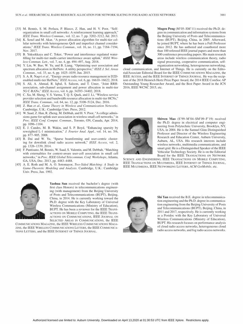
SUN et al.: HIERARCHICAL RADIO RESOURCE ALLOCATION FOR NETWORK SLICING IN FOG RADIO ACCESS NETWORKS 3881
[33] M. Bennis, S. M. Perlaza, P. Blasco, Z. Han, and H. V. Poor, “Self-organization in small cell networks: A reinforcement learning approach,”IEEE Trans. Wireless Commun., vol. 12, no. 7, pp. 3202–3212, Jul. 2013.
[34] K. Senel and M. Akar, “A power allocation algorithm for multi-tier cel-lular networks with heterogeneous QoS and imperfect channel consider-ations,” IEEE Trans. Wireless Commun., vol. 16, no. 11, pp. 7184–7194,Nov. 2017.
[35] B. Yuksekkaya and C. Toker, “Power and interference regulated water-filling for multi-tier multi-carrier interference aware uplink,” IEEE Wire-less Commun. Lett., vol. 7, no. 4, pp. 494–497, Aug. 2018.
[36] Y. Lin, W. Bao, W. Yu, and B. Liang, “Optimizing user association andspectrum allocation in HetNets: A utility perspective,” IEEE J. Sel. AreasCommun., vol. 33, no. 6, pp. 1025–1039, Jun. 2015.
[37] S. A. R. Naqvi et al., “Energy-aware radio resource management in D2D-enabled multi-tier HetNets,” IEEE Access, vol. 6, pp. 16610–16622, 2018.
[38] S. Ali, A. Ahmad, R. Iqbal, S. Saleem, and T. Umer, “Joint RRH-association, sub-channel assignment and power allocation in multi-tier5G C-RANs,” IEEE Access, vol. 6, pp. 34393–34402, 2018.
[39] C. Xu, M. Sheng, V. S. Varma, T. Q. S. Quek, and J. Li, “Wireless serviceprovider selection and bandwidth resource allocation in multi-tier HCNs,”IEEE Trans. Commun., vol. 64, no. 12, pp. 5108–5124, Dec. 2016.
[40] Z. Han et al., Game Theory in Wireless and Communication Networks.Cambridge, U.K.: Cambridge Univ. Press, 2012.
[41] W. Saad, Z. Han, R. Zheng, M. Debbah, and H. V. Poor, “A college admis-sions game for uplink user association in wireless small cell networks,” inProc. IEEE Conf. Comput. Commun., Toronto, ON, Canada, Apr. 2014,pp. 1096–1104.
[42] E. J. Candes, M. B. Wakin, and S. P. Boyd, “Enhancing sparsity byreweighted L-1 minimization,” J. Fourier Anal. Appl., vol. 14, no. 5/6,pp. 877–905, 2008.
[43] B. Dai and W. Yu, “Sparse beamforming and user-centric cluster-ing for downlink cloud radio access network,” IEEE Access, vol. 2,pp. 1326–1339, 2014.
[44] F. Pantisano, M. Bennis, W. Saad, S. Valentin, and M. Debbah, “Matchingwith externalities for context-aware user-cell association in small cellnetworks,” in Proc. IEEE Global Telecommun. Conf. Workshops, Atlanta,GA, USA, Dec. 2013, pp. 4483–4488.
[45] A. E. Roth and M. A. O. Sotomayor, Two-Sided Matching: A Study inGame-Theoretic Modeling and Analysis. Cambridge, U.K.: CambridgeUniv. Press, Jun. 1992.
Yaohua Sun received the bachelor’s degree (withfirst class Honors) in telecommunications engineer-ing (with management) from the Beijing Universityof Posts and Telecommunications (BUPT), Beijing,China, in 2014. He is currently working toward thePh.D. degree with the Key Laboratory of UniversalWireless Communications (Ministry of Education),BUPT. He has been a reviewer for the IEEE TRANS-ACTIONS ON MOBILE COMPUTING, the IEEE TRANS-ACTIONS ON COMMUNICATIONS, IEEE JOURNAL ON
SELECTED AREAS IN COMMUNICATIONS, the IEEECOMMUNICATIONS MAGAZINE, the IEEE WIRELESS COMMUNICATIONS MAGA-ZINE, the IEEE WIRELESS COMMUNICATIONS LETTERS, the IEEE COMMUNICA-TIONS LETTERS, and the IEEE INTERNET OF THINGS JOURNAL.
Mugen Peng (M’05–SM’11) received the Ph.D. de-gree in communication and information systems fromthe Beijing University of Posts and Telecommunica-tions (BUPT), Beijing, China, in 2005. Afterward,he joined BUPT, where he has been a Full Professorsince 2012. He has authored and coauthored morethan 100 refereed IEEE journal papers and more than300 conference proceeding papers. His main researchareas include wireless communication theory, radiosignal processing, cooperative communication, self-organization networking, heterogeneous networking,
cloud communication, and Internet of Things. He is currently on the Edito-rial/Associate Editorial Board for the IEEE COMMUNICATIONS MAGAZINE, theIEEE ACCESS, and the IEEE INTERNET OF THINGS JOURNAL. He was the recip-ient of the 2018 Heinrich Hertz Prize Paper Award, the 2014 IEEE ComSoc APOutstanding Young Researcher Award, and the Best Paper Award in the JCN2016, IEEE WCNC 2015, etc.
Shiwen Mao (S’99–M’04–SM’09–F’19) receivedthe Ph.D. degree in electrical and computer engi-neering from Polytechnic University, Brooklyn, NY,USA, in 2004. He is the Samuel Ginn DistinguishedProfessor and Director of the Wireless EngineeringResearch and Education Center, Auburn University,Auburn, AL, USA. His research interests includewireless networks, multimedia communications, andsmart grid. He is a Distinguished Speaker of the IEEEVehicular Technology Society. He is on the EditorialBoard for the IEEE TRANSACTIONS ON NETWORK
SCIENCE AND ENGINEERING, IEEE TRANSACTIONS ON MOBILE COMPUTING,IEEE TRANSACTIONS ON MULTIMEDIA, IEEE INTERNET OF THINGS JOURNAL,IEEE MULTIMEDIA, IEEE NETWORKING LETTERS, ACM GetMobile, etc.
Shi Yan received the B.E. degree in telecommunica-tion engineering and the Ph.D. degree in communica-tion engineering from the Beijing University of Postsand Telecommunications (BUPT), Beijing, China, in2011 and 2017, respectively. He is currently workingas a Postdoc with the Key Laboratory of UniversalWireless Communications (Ministry of Education),BUPT. His research focuses on performance analysisof cloud radio access networks, heterogeneous cloudradio access networks, and fog radio access networks.
Authorized licensed use limited to: Auburn University. Downloaded on April 13,2020 at 01:30:53 UTC from IEEE Xplore. Restrictions apply.