Embed Size (px)
Citation preview

August 13, 2013 11:37 Hybridmodelreg
Vol. 00, No. 00, Month 200x, 1–19
Hierarchical Hybrid Modeling and Control of an Unmanned Helicopter
Ali Karimoddinia, Hai Linb⇤, Ben M. Chen,c, and Tong H. Leec
aDepartment of Electrical and Control Engineering, North Carolina Agricultural and Technical StateUniversity Greensboro, NC 27411
bDepartment of Electrical Engineering, University of Notre Dame, Notre Dame, IN 46556cGraduate School for Integrative Sciences and Engineering (NGS) and Department of Electrical and
Control Engineering (ECE), National University of Singapore;
(Received 00 Month 200x; final version received 00 Month 200x)
In this paper, we propose a hybrid modeling and control design scheme for a unmanned helicopter. Thiscontrol structure has a hierarchical form with three layers: the regulation layer, the motion planning layer, andthe supervision layer. For each layer, a separate hybrid controller has been developed. Then, a compositionoperator is adopted to capture the interactions between these layers. The resulting closed-loop system canflexibly command the helicopter to perform di↵erent tasks, autonomously. The designed controller is embeddedin the avionic system of the NUS UAV helicopter, and actual flight test results are presented to demonstratethe e↵ectiveness of the proposed control structure.
Keywords: hybrid modelling and control theory, hierarchical control, unmanned aerial vehicles, flightcontrol.
1 Introduction
Over recent years Unmanned Aerial Vehicles (UAVs) have attracted researcher from both mili-tary and academic sides due to the wide range of applications of UAVs. However, their complexityof modelling and control imposes many technical and theoretical challenges (Ollero and Merino2004). A very important issue here is to develop a UAV which is able to perform di↵erent mis-sions autonomously. A typical mission is composed of several tasks for which separate controllersare required to be designed. Then, a decision making unit needs to be embedded to coordinatethe controllers based on assigned tasks. Hence, the control structure of a UAV has a hybridnature, which includes both continuous and discrete dynamics that interactively coexist in thesystem (Sobh and Benhabib 1997). It is common to treat the discrete and continuous dynamicsof the UAVs in a decoupled way, (Dong et al. 2007), (Fatemi et al. 2008), which simplifies thedesign procedure. However, the ignorance of the discrete dynamics and its coupling e↵ect on thecontinuous evolution of the system is questionable and may degrade the reliability of the system(Karimoddini et al. 2009).To address this problem, one solution is to use hybrid modelling and control theory to uniformly
model and handle both discrete and continuous dynamics of the system (Antsaklis and Nerode1998). To explore the applications of hybrid modelling and control theory in the sophisticatedstructures of UAVs, in (Bayraktar et al. 2004), a hybrid controller is developed for the control
Financial supports from NSF-CNS-1239222 and NSF-EECS-1253488 for this work are greatly acknowledged. A primaryversion of this paper was presented in the 18th World Congress of the International Federation of Automatic Control (IFAC2012).⇤Corresponding author: H. Lin, email: [email protected], Tel. 574-6313177.
ISSN: 0020-7179 print/ISSN 1366-5820 onlinec� 200x Taylor & FrancisDOI: 10.1080/0020717YYxxxxxxxxhttp://www.informaworld.com
August 13, 2013 11:37 Hybridmodelreg
2
of the altitude and turning rate of a fixed wing UAV. For quadrotors, in (Gillula et al. 2010), ahybrid model for the backflit maneuvering is provided for which a forward reachability analysisguarantees the switching sequence for correct execution of the task. Similarly in (Naldi et al.2009), a robust reachability analysis is given for taking o↵ and landing of a ductedfan aerialvehicle. When the vehicle is landing, upon contacting with the ground, the control dynamicswill be changed. So, the hybrid controller pushes the switching sequence to safely land on theground. In (Frazzoli et al. 2000), the path planning of a UAV helicopter is translated to a robusthybrid analysis problem and the results are verified through simulation, and in (Schouwenaarset al. 2003), a hybrid controller for the velocity control of a helicopter is provided where MixedInteger Linear Programming (MILP) is used for the optimal reference generation. In contrast,in this paper, instead of focusing on a specific task, our aim is to propose a framework for thehybrid control of a UAV helicopter so that it can autonomously accomplish the assigned mission.To reduce the complexity of the system and to facilitate the design procedure, we have developeda hierarchical control structure in a systematic way to distribute the control tasks among thelayers. The use of hierarchical control and its application to coordination problems have beenstudied for a long time (Mesarovic et al. 1970), (Findeisen et al. 1980); however, considering theconcept of hierarchical control within hybrid framework still is a challenging problem.Hence, the contribution of this paper is that firstly we have proposed a formal hierarchical
hybrid modelling and control approach for UAV systems. The control system has three layers: theregulation layer, which is responsible for the low level control; the motion planning layer, whichis responsible for path generation to be followed by the regulation layer, and the supervisionlayer, which is the decision making unit and is responsible for managing the switching scenarioto perform a mission autonomously. Each layer has been modelled with an Input/Output hybridautomaton (Lynch et al. 2003). Then, we have introduced a composition operator to synchronisethe layers and capture the interplay between them. The existing definitions of compositionoperator either are only useful for fully connected systems (Johansson 2005), or cannot refinethe discrete transitions or states of the system (Lynch et al. 2001), (Rashid and Lygeros 1999).In contrast, in this paper, a new composition operator is proposed that is able to be used forpartially connected systems and can refine the discrete transitions and states in an e�cient way.Finally, the designed controller is implemented on the NUS UAV helicopter (Peng et al. 2009),
and real flight tests are conducted to evaluate the proposed hybrid control structure. The flighttest results show that the designed control system can be e↵ectively involved in a complexmission composed of several tasks.The remaining parts of this paper are organized as follows. First, in Section 2, the model of
the NUS UAV helicopter is described to be used in our further derivations. Then, in Section 3,a hierarchical hybrid framework has been developed for this UAV helicopter and the layers ofthis hierarchy are discussed in detail. The experimental results are presented in Section 4, andfinally, the paper is concluded in Section 5.
2 The UAV Model and Structure
Before developing a hybrid controller for a UAV helicopter, its model and structure is briefly ex-plained in this section. Here, the test-bed is the NUS UAV helicopter (Fig. 1), which is developedby our research group in the National University of Singapore. This helicopter is a Raptor-90helicopter, which is equipped with an avionic system, including the onboard computer system,the sensors, and the actuators that together generate the control signals for an automatic flight.The construction procedure of such an autonomous UAV is described in (Cai et al. 2008), thehardware details are explained in (Cai et al. 2005), and its low level flight control performanceis discussed in (Peng et al. 2009).Based on the first-principles modeling approach detailed in (Cai et al. 2008), a nonlinear
dynamic model for the NUS UAV helicopter has been obtained, which is highly accurate in awide range of flight envelope. Using the trust-region dogleg method, the obtained model then

August 13, 2013 11:37 Hybridmodelreg
3
Figure 1. An Autonomous UAV Helicopter.
has been linearized at the hovering state in which the linear and angular velocities, the pitchangle, and the roll angle of the UAV are close to zero (Cai et al. 2006). To capture the UAVdynamics, it is required to consider two coordinate systems. The moment and force equationsmust be derived in a moving coordinate system whose origin is located at the center of gravityof the UAV, whereas to obtain the net displacement of the UAV, we need to consider a fixedcoordinate system that is centered in the flight starting point. The moving and fixed coordinatesystems are called the body frame and the ground frame, respectively.Deriving the force and moment equations in the body frame of the UAV and linearizing the
resulting nonlinear model at the hovering state, will result in the following model:
xin = Axin +Bu, (1)
where xin = [ Vx(m/s) Vy(m/s) !x(rad/s) !y(m/s) �(rad) ✓(rad) a1(rad) b1(rad) Vz(m/s)!z(rad/s) wzf (rad/s) ]
0 is the internal state of the system. Here, Vx, Vy, and Vz are the linearvelocities; !x, !y, and !z are the angular velocities; � is the roll angle; ✓ is the pitch angle; a1and b1 are the flapping angles, and wzf is the state variable of the gyro rate that introduces afirst order di↵erential equation to capture the e↵ect of �pedal (Peng et al. 2006). Furthermore,
u =⇥�roll(rad) �pitch(rad) �col(rad) �pedal(rad)
⇤0is the vector of the control input signals, to
be given to the servos to control the angle of the blades and to drive the UAV in di↵erentdirections. Finally, w = (uwind, vwind, wwind) is the wind gust disturbance where uwind, vwind,wwind a↵ect the UAV velocities in the x, y and z directions, respectively. The state and inputmatrices A and B of the corresponding linearized model, and the disturbance matrix E are asfollows:
A =
A2 08⇥3
03⇥8 A1
�, B =
B2 08⇥2
03⇥2 B1
�, E =
E2 08⇥1
03⇥2 E1
�
where
A1 =
"�0.6821 �0.1070 0�0.1446 �5.5561 �36.6740
0 2.7492 �11.1120
#, B1 =
"15.6491 01.6349 �58.4053
0 0
#, E1 =

August 13, 2013 11:37 Hybridmodelreg
4
"�0.5995�1.3832
0
#, B2 =
2
666666664
0 00 00 00 00 00 0
0.0496 2.62242.4928 0.1740
3
777777775
, E2 =
2
666666664
�0.1778 00 �0.3104
�0.3326 �0.20510.0802 �0.2940
0 00 00 00 0
3
777777775
, A2 =
2
666666664
�0.1778 0 0 0 0 �9.7807 �9.7808 00 �0.3104 0 0 9.7807 0 0 9.7807
�0.3326 �0.5353 0 0 0 0 75.7640 343.86�0.1903 �0.2940 0 0 0 0 172.620 �59.958
0 0 1 0 0 0 0 00 0 0 1 0 0 0 00 0 0 �1 0 0 �8.1222 4.65350 0 �1 0 0 0 �0.0921 �8.1222
3
777777775
.
To obtain the net displacement of the UAV, xout, we should first obtain the velocity vector inthe ground frame as a fixed coordinate system, and then, the integration of the velocity vectorin the fixed frame will yield the net displacement:
xout = ⌦0(⇥)Cxin, (2)
where xout = [ x(m) y(m) z(m) (rad)]0. Here, x, y, and z describe the position of the UAV inthe ground frame, is its heading angle, and ⇥ = [�, ✓, ]T is the orientation vector. MatrixC and the block ⌦(⇥) are as follows:
C =
2
64
1 0 0 0 0 0 0 0 0 0 00 1 0 0 0 0 0 0 0 0 00 0 0 0 0 0 0 0 1 0 00 0 0 0 0 0 0 0 0 1 0
3
75, ⌦(⇥) =
R(⇥) 00 1
�,
where the block R(⇥) is a transformation matrix from the ground frame to the body frameand it has the following form:
R(⇥) =
2
4cos ✓ cos cos ✓ sin �sin ✓
�cos� sin + sin�sin ✓ cos cos� cos + sin�sin ✓ sin sin� cos✓sin� sin + cos�sin ✓ cos �sin� cos + cos�sin ✓ cos cos� cos✓
3
5 (3)
.The model diagram of the UAV helicopter is depicted in Fig. 2. In the next section, we will
discuss about the control design for this semi-linearized model of the UAV within the hybridmodelling and control framework.
Figure 2. The diagram of the UAV model.
3 Hybrid Modelling and Control of an Unmanned Helicopter
3.1 Hierarchical Hybrid Modelling and Control of an Unmanned Helicopter
To design a fully autonomous controller for this helicopter, we propose a hierarchical hybridcontrol structure that consists of three layers: the Regulation layer, the Motion planning layer,and the Supervision layer. Each layer has a hybrid structure and is responsible to do a specific

August 13, 2013 11:37 Hybridmodelreg
5
task. The relation between these layers can be described by hybrid composition operator. Fig .3shows the overall picture of this system and describes the nature and objectives of each layer.The philosophy behind this hierarchy is that the lower levels are involved in more details such asreference tracking and stability analysis, while the higher levels mostly manage and coordinatethe control scenarios to achieve the assigned task. The advantage of this structure is that itsimplifies the design procedure so that each layer can be developed to accomplish a particularpart of the control task. Next, we will describe the layers of this control hierarchy.
Figure 3. Hierarchical hybrid control structure of an autonomous UAV Helicopter.
3.2 The Regulation Layer
The regulation layer is directly connected to the UAV avionic system and can manipulate theactuators and gather the sensors reading for the control process. It also receives the task schedul-ing commands from the motion planning layer to activate proper control modes. For di↵erentvelocities and situations, di↵erent controllers can be designed. For example, in (Cai et al. 2010),several controllers have been designed for di↵erent modes of operation of the NUS UAV heli-copter. Then, the higher layers are responsible to activate the proper control modes. To elaboratethe idea of hierarchical control, without loss of generality, here we consider two control modesfor the regulation layer of this UAV as described in the following parts.
3.2.1 Velocity Control Mode
In the velocity control mode (vc), one can stabilize the attitude of the helicopter and controlthe UAV to move with the desired velocity vector (vx, vy, vz) and the desired yaw rate, wz. Forthis purpose, we will use an H1 controller by which both the robust stability and a properperformance of the system can be achieved, simultaneously. To design a H1 controller, first,looking at matrices A, B, and E in (1), it can be seen that, the model is a decoupled systemwith two separate subsystems as follows:
x1 = A1x1 +B1u1 + E1w1 (4)
x2 = A2x2 +B2u2 + E2w2 (5)
where x1 = [ Vzb(m/s) !zb(rad/s) wzf (rad/s) ]0, u1 = [ �col �pedal ]0, x2 = [ Vxb(m/s) Vyb(m/s)
!xb(rad/s) !yb(rad/s) �(rad) ✓(rad) as(rad) bs(rad) ]0, and u2 = [ �roll(rad) �pitch(rad) ]0.
Now, starting with Subsystem 1, and using the notation analogous with (Chen 2000), we definethe measurement output simply as the state feedback in the form of y1 = C11x1 with C11 = I.

August 13, 2013 11:37 Hybridmodelreg
6
Also, we define the controlled output h1 in the form of h1 = C12x+D12u, where
C12 =
2
664
02⇥3
3.1623 0 00 3.1623 00 0 1.7321
3
775 , D12 =
2
444.7214 0
0 28.284303⇥2
3
5 (6)
The nonzero entries of C12 and D12 are used for tuning the controller. Here, they are deter-mined experimentally to achieve the desired performance. Meanwhile, the H1 design guaranteesinternal stability and robustness of the system. Indeed, H1 control design reduces the e↵ect ofthe wind gust disturbance on the control performance, by minimizing theH1 norm of the closed-loop transfer matrix from the disturbance w to the controlled output h1, denoted by T1. TheH1 norm of the transfer function T1 is defined as follows:
kT1k1 = sup0!<1
�max[T1(j!)] (7)
where �max[⇤] denotes the maximum singular value of the matrix ⇤.Having the matrices C12 and D12, one can find �⇤1, which is the optimal H1 performance for
the closed-loop system from the disturbance input w to the controlled output h1 over all thepossible controllers that internally stabilize the system. As practically, �⇤1 is not achievable, wewill try to reach �1, which is slightly larger than �⇤1.With this choice of the control parameters, D11 and D12 are full rank and the quadruples
(A1, B1, C12, D12) and (A1, E1, C11, D11) are left invertible and are free of invariant zeros. There-fore, we have a so-called regular problem, for which we can use the well-established H1 controltheory (Chen 2000). As it was mentioned, the resulting closed loop system suboptimality min-imizes the H1 norm of the transfer function from the disturbance w to the controlled outputh1. As a result, F1 is the H1 control gain that can be achieved as follows:
F1 = �(D012D12)
�1(D012C12 +B0
1P1) (8)
where matrix P1 is the positive semi-definite solution of the following H1 algebraic Riccatiequation:
A01P1 + P1A1 + C 0
12C12 + P1E1E01P1/�
2 �
(P1B1 + C 012D12)(D
012D12)
�1(D012C12 +B0
1P1) = 0 (9)
For this system and these control parameters values, the value of �⇤1 is 1.4516.
Choosing �1 = 1.4616, will lead to F1 =
�0.0935 �0.0005 0.00270.0008 0.0364 �0.0481
�. The same proce-
dure can be followed for Subsystem 2, and the resulting feedback gain will be F2 =0.0017 �0.1683 �0.0486 0.0081 �1.9336 �0.1974 �0.3227 �2.14440.0815 �0.0461 �0.0087 �0.0535 �0.3908 �1.0690 �1.1712 �0.4659
�. Then, considering these two
subsystems together, the control law will be in the form of u = Fxin + Gr (Fig. 4), where
matrix F =
F2 00 F1
�was obtained through the robust H1 design technique, and G =
�(C(A + BF )�1B)�1 is the feedforward gain, obtained from the inverse of the system steadystate gain.
3.2.2 Position Control Mode
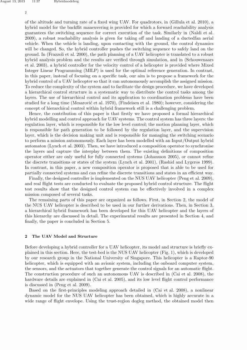
The control objective in the position control mode, (pc), is to drive the UAV to follow thedesired path. In other words, the state variable xout should track the given reference r. Thecontrol law for this operation mode is u = Fxin + G⌦Kp(r � xout). As it is shown in Fig. 5,
August 13, 2013 11:37 Hybridmodelreg
7
Figure 4. The controller for the velocity-control of the UAV.
this controller consists of two layers: the inner-loop and the outer-loop. The inner-loop controllerstabilizes the attitude of the UAV, and its parameters, F and G, are selected as the same asthe velocity control mode. The outer-loop controller, however, smoothly drives the UAV to thedesired position. In the outer-loop the block ⌦ is used to compensate for the transformation ma-trix ⌦0, as they have the property that ⌦⌦0 = I, and Kp is a P-controller. In (Karimoddini et al.2010), a tractable procedure has been proposed for the design of a decentralized P-controller, Kp,for multi-variable systems, based on the generalized Nyquist theorem and disturbance analysis.
Figure 5. The controller for the position-control of the UAV.
3.2.3 Hybrid Model of the Regulation Layer
Now, we can present the hybrid model of the regulation layer based on what explained for eachcontrol mode. Both control modes have the same plant dynamics xin = Axin+Bu; however, thecontrol law in the velocity control mode is u = Fxin +Gr, and in the position control mode isu = Fxin +G⌦Kp(r � xout).The graph representation of the hybrid model of the regulation layer is shown
in Fig. 6. Formally, this hybrid model of the regulation layer can be de-scribed by a hybrid automaton ((Lynch et al. 2003), (Liu et al. 1999)) HR =(VR, XR, UR, YR, fR, InitR, InvR, ER, GuardR, ResetR, hR), where
• VR = {start, vc, pc} is the set of discrete states, where vc and pc stand for the velocity controlmode and the position control mode, respectively. The start mode is used for the initializationof the system to choose either of the modes.
• XR = [xin, xout]0 is the continuous state of the system.• UR = UDR
⇥UCRis the input space, where UCR
= r ✓ R4 is the continuous control input, andUDR
= {cmdV , cmdP } is the set of discrete inputs. The subscripts denote the correspondingending discrete states in Fig. 6. For instance, cmdP is the command that fires a transition tothe position control mode.
• YR = YDR⇥ YCR
is the system output, where here, YCR= xout and YDR
= VR feedback thecurrent state of the system to the motion planning layer to be able to generate appropriatereference signals.
• fR : VR⇥XR⇥UR ! XR is the vector field description of the system that is defined as follows:x = fR(v, x, u) = fR(v, x, r) =

August 13, 2013 11:37 Hybridmodelreg
8
Figure 6. The hybrid model for the regulation layer.
8>>>><
>>>>:
0 if v = start(A+BF )xin +BGr
⌦0Cxin
�if v = vc
(A+BF )xin �BG⌦Kpxout +BG⌦Kpr
⌦0Cxin
�if v = pc
• InitR = {(start, 0)} ✓ VR ⇥XR is the set of initial states of the UAV.• InvR ✓ VR ⇥ XR ⇥ UR is the invariant condition. Here, it is required that for both discrete
modes, z > 0, vx, vy, vx < 3.5m/s, !z < 15deg/s and a, b, ✓,� < ⇡6 .
• ER ✓ VR⇥VR is the set of discrete transitions. Here, E = {(Start, vc), (start, pc), (pc, vc), (vc, pc), (pc, pc), (vc, vc)}.
• GuardR : ER ! 2XR⇥UR describes the guard conditions for the discrete transitions. For eachdiscrete transition from the vertex v to v0, the continuous state of the system and the controlinput should belong to Guard(v, v0). For instance, in Fig. 6, when the system is in mode vc,the control input cmdP can cause a transition to the mode pc. In the guard map for thistransition, no condition has been considered on the continuous state of the system, and onlythe discrete control input is used for the guard condition.
• ResetR : ER ⇥XR ⇥ UR ! 2XR describes the reset map. For instance, z0 2 Reset(v, v0, z, w)shows that for (v, v0) 2 E, z 2 X, and w 2 U , there is a transition for which the continuousstate of the system will be reset to z0. Here, the reset map is an identity map as there is nojump on the continuous state of the system. when the reset map is an identity map, it is notshown in the graph representation.
• hR : VR ⇥XR ! YR is the output map. Here we have h(v, x) = xout.
3.3 Motion Planning Layer
Based on the feedbacked information received from the regulation layer, the motion planninglayer can activate the corresponding control mode in the regulation layer and can generate propercontrol references in the form of a feasible path to be tracked by the regulation layer. The pathgeneration mechanism could be done in an o↵-line manner or through a dynamic path planningmechanism:

August 13, 2013 11:37 Hybridmodelreg
9
3.3.1 O↵-line Path Generation Mechanism
In this method, based on the problem requirements, an optimal path can be gener-ated and stored in the library of the system. As an example, we explain a motion plan-ning layer that has been used in our flight tests using o↵-line path generation mech-anism. The hybrid automaton for this model of the motion planning layer is HP =(VP , XP , UP , YP , fP , InitP , InvP , EP , GuardP , ResetP , hp) where Xp = (rx, ry, rz, r ) is the con-tinuous state of the motion planning layer and indeed, it is the generated reference that is goingto be given to the regulation layer. The discrete state is Vp = {Startp, Path � Zp, Path � Cp,Ascendp, Hoverp, V elp, Descendp, Emergencyp} where Startp, PathZp, PathCp, Ascendp,Hoverp, V elp, Descendp, and Emergencyp stand for starting the task, zigzag path tracking,circle path tracking, ascending, hovering, generating velocity references, descending, and emer-gency mode, respectively. Here, the control signal is Up = UCp
⇥ UDpwhere UCp
= XR is thecurrent state of the system that is feedbacked from the regulation layer and UDp
= {cmdPathZ ,cmdPathC , cmdAscend, cmdHover, cmdV el, cmdDescend, cmdEmergency} is the command receivedfrom the supervision layer. When the motion planning layer receives one of these commands,it switches to the corresponding discrete mode. Yp = YDp
⇥ YCpis the layer output. Here,
YCp= XP is the continuous part, which informs the supervision layer about the current state
of the motion planning layer and also, it will be given to the regulation layer as the generatedreference to be tracked. YDp
= YDpr⇥YDps
is the discrete output signal where YDps= Vp is given
to the supervisor to inform about the current discrete mode of the motion planning layer andYDpr
= {cmdp, cmdv} is the command that activates the proper control mode in the regulationlayer:
YDpr=
⇢cmdp for Vp = PathCp, PathZp, Ascendp, Descendpcmdv for Vp = V elp, Emergencyp, , HoverP
The dynamics of the motion planning layer is
Xp(v) = [ xr yr zr r ]T =
8>>>>>><
>>>>>>:
(0, 0, fza(t), 0) v = Ascendp fz(t) > 0(0, 0, fzd(t), 0) v = Descendp fz(t) < 0(fxpc(t), fypc(t), fzpc(t), f pc
(t)) v = PathCp
(fxpz(t), fypz(t), fzpz(t), f pz(t)) v = PathZp
(fxv(t), fyv(t), fzv(t), f v(t)) v = V elp
(0, 0, 0, 0) v = Emergencyp, Hoverp
In the graph representation for the hybrid model of the motion planning layer, all discrete statesare connected, and the command cmd⇤ can fire a transition to the state ⇤. There is no guardcondition and jump for the discrete transitions. As this graph is tedious, we have not shown ithere.
3.3.2 On-line Path Generation Mechanism
Here, the objective is to generate the references in an on-line way to be tracked by the regu-lation layer. The basic path planning problem in which a robot have to be driven from the startpoint towards the destination point while respecting the constraints, is a standard optimal con-trol problem and has been addressed with di↵erent methods such as potential function, mixedinteger linear programming, cell decompositions and probabilistic roadmaps (Latombe 1990).But, these methods are not able to address more advance path planning problems when thereare number of goals with a particular order of execution. The alternative solution is to utilizesymbolic motion planning approaches (Belta et al. 2007) by which it is possible to generate apath associated with a sequence of symbols, which can follow logical supervisory rules. For thispurpose, one can introduce an abstract system xp(t) = fp(xp(t), up(t)), which is simpler than theoriginal model of the regulation layer as it ignores some unnecessary information. This abstract
August 13, 2013 11:37 Hybridmodelreg
10
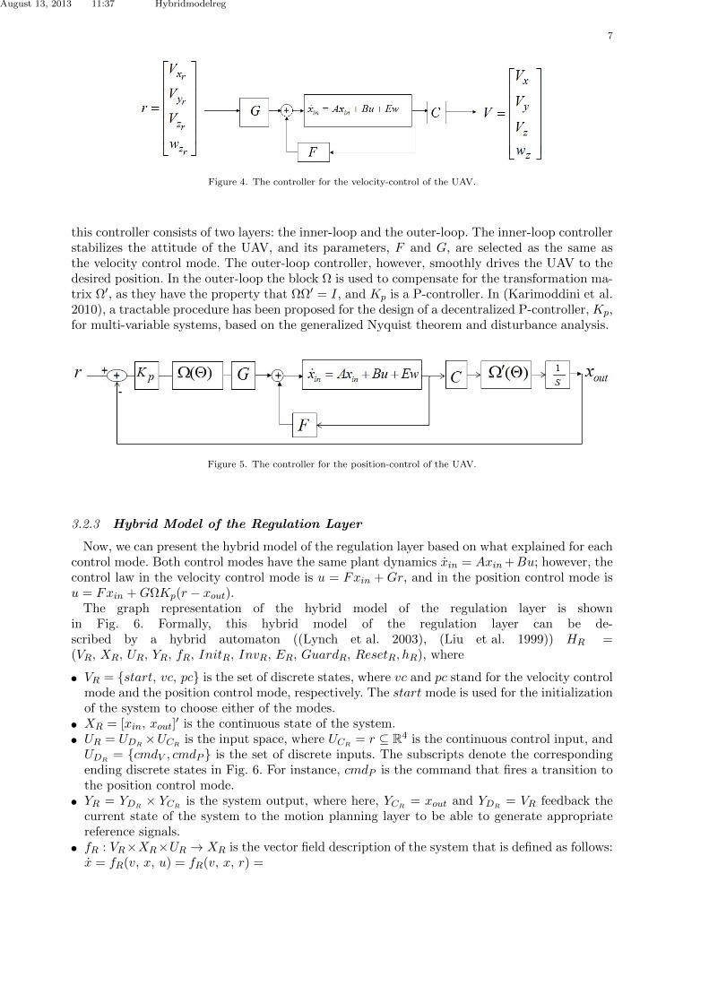
system should be approximately similar to the regulation layer dynamics so that the regulationlayer can follow the generated reference. To elaborate the idea, let us work on the design of themotion planning layer for one of the NUS UAV helicopters that is involved in a leader followerformation mission as a follower. As we explained, for the regulation layer of this helicopter wehave used a multi-layer control structure whose inner-loop controller stabilizes the system usingH1 control design techniques and its outer-loop is used to drive the system towards the desiredposition (Fig. 7). Assuming that the inner-loop is fast enough to track the given references (Ka-rimoddini et al. 2011), the inner-loop can be approximated by an identity matrix. Therefore, theregulation layer dynamics is approximately as xp = up, where xp is the outer loop state variable,and up is a control parameter, which should be designed by the formation algorithm.
Figure 7. Control Structure of the UAV.
Considering the follower velocity in the form of Vfollower = Vleader + Vrel, we can imagine arelative coordinate system in which the leader has a relatively fixed position and hence, theformation problem is reduced to drive the follower UAV towards the desired position. For thispurpose, in (Karimoddini et al. 2012), we have introduced a hybrid symbolic approach basedon spherically partitioning of the space. Consider an sphere SRm
, with the radius of Rm thatis centered at the desired position. The sphere is partitioned into several sectors as shown inFig. 8. To reach the formation, the system’s trajectory should reach one of the sectors adja-cent to the sphere’s origin, and to maintain the formation, the system trajectory should remainthere for ever. Meanwhile, the follower UAV should avoid the collision with the leader UAV.These tasks can be achieved by properly driving the system trajectory through the partitionedspace. Since the motion planning dynamics has a linear form, the control up can be constructedas the convex combinations of control signals on the vertices, so that, the system trajectoryeither remain inside one of the sectors or exit form a desired facet. The resulting control sig-nal is in the form of up(Cmd⇤) =
Pvm�muvm(Cmd⇤), m = 0, 1, ..., 7, where 0 �m 1
are coe�cients, uvm(Cmd⇤) are the control values at the vertices, and Cmd⇤ is the discretecommand, which could be CmdR, CmdK , or CmdC that stand for the commands for reach-ing the formation, keeping the formation, and collision avoidance, respectively. Further detailsabout this online path generation mechanism are available in (Karimoddini et al. 2012). Usingthis method, the hybrid model for the motion planning layer of the follower unmanned he-licopter is HP = (VP , XP , UP , YP , fP , InitP , InvP , EP , GuardP , ResetP , hP ) as the the hybridmodel for this layer, where Xp = (rx, ry, rz, r ) as the continuous state of the motion plan-ning layer. The discrete state is Vp = { Startp, Hoverp, ReachFormationp, KeepFormationp,CollisionAvoidancep}. Similar to the previous case, the control signal is Up = UCp
⇥UDpwhere
UCp= XR, and UDp
= UDpr⇥ UDps
. The set UDps= {cmdH , cmdR, cmdK , cmdC} is the com-
mand received from the supervision layer, and UDpris the the information about the current
discrete mode of the regulation layer. The subscripts R, K, C, and H stand for reaching theformation, keeping the formation, collision avoidance, and hovering, respectively. The output isYp = YDp
⇥ YCp, where YCp
= XP is the continuous part and YDp= YDpr
⇥ YDpsis the discrete
output signal where YDps= Vp is the discrete output to be given to the supervisor to inform

August 13, 2013 11:37 Hybridmodelreg
11
about the current discrete mode of the motion planning layer and YDpr= {cmdp, cmdv} is the
command that activates the proper control mode in the regulation layer:
YDpr=
⇢cmdv for Vp = HoverPcmdp for Vp = ReachFormationp, KeepFormationp, CollisionAvoidancep
Figure 8. A spherically partitioned space.
The dynamics of the motion planning layer is as follows:xp(v) = [ xr yr zr r ]
T =8>><
>>:
Pvm�muvm(CmdR) form = 0, 1, ..., 7, v = ReachingFormationpP
vm�muvm(CmdK) form = 0, 1, ..., 7, v = KeepFormationpP
vm�muvm(CmdC) form = 0, 1, ..., 7, v = CollisionAvoidancep
0 for v = HoverpThe transitions for this hybrid model are shown in the graph representation of the system in
Fig. 9.
Figure 9. The hybrid model for the motion planning layer for a formation mission.
3.4 Supervision Layer
This layer is responsible for the decision making and task scheduling for the mission that shouldbe performed by the UAV. The supervision layer can be presented by a purely discrete automaton(Ramadge and Wonham 1989) or a timed automaton (Alur and Dill 1994), which are subclasses

August 13, 2013 11:37 Hybridmodelreg
12
of hybrid systems. Using the o↵-line path planning mechanism for the motion planning layer,described in the previous section, a supervision layer has been designed for a typical missionshown in Fig. 10. This mission starts with 8 meters ascending, followed by 15 Sec hovering, 60Sec zigzag path tracking, 35 Sec velocity control, 42 Sec circle path tracking, 20 Sec hovering,and 8 meters descending. The mission ends with hovering. For safety issues, when the measuredsignals are out of range, the fuel level sensor alarms, or other possible problems occur, a faultsignal is generated, which leads the system to the emergency mode. The discrete states andcorresponding discrete outputs are shown in Fig. 10. These discrete outputs are commands thatactivate a control mode in the motion planning layer. The input space of this layer is in theform of Us = UCs
⇥ UDswhere UCs
= YCps= XP is the current state of the path planner,
and UDs= UDse
⇥ UDspwhere UDsp
= YDps= Vp is the information about the current discrete
mode of the motion planning layer, and UDse= {CmdStartMission, Fault} are the external events
generated by the other sources. Here, the command CmdStartMission is generated by the groundstation, and the command Fault is generated by the UAV event generation mechanism for faultycases (e.g., when the measurement values are out of range). The graph representation for thissupervisor is shown in Fig. 10.
Figure 10. The supervision layer for a mission with successive tasks generated with o↵-line path generation mechanism.
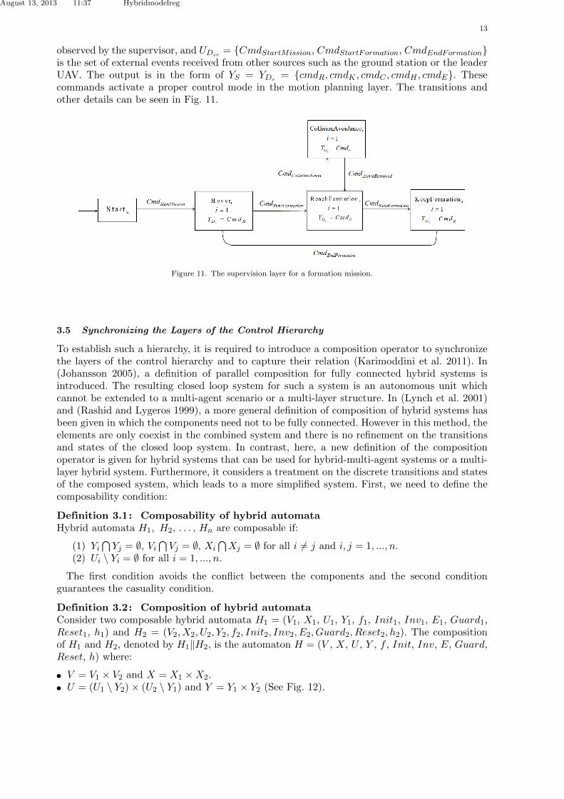
As another example, using the motion planning layer for the on-line path planning, a supervisorhas been designed for a follower UAV involved in a formation mission as shown in Fig. 11. Itstarts with the hovering. When the follower receives the event CmdStartFormation from the leader,it switches to the ReachFormations mode. If the supervisor detects a collision alarm, an eventCmdCollisionAlarm will be generated and the system switches to the CollisionAvoidances mode.Disappearing the collision alarm, the command CmdAlarmRemoved causes a transition to the theReachFormations mode to resume the formation. Finally, when the formation is achieved, thesystem switches to the KeepFormations mode. The input space for this supervisor is in the formof Us = UCs
⇥ UDswhere UCs
= YCps= XP is the current state of the path planner, and UDs
=UDse
⇥UDss⇥UDsp
where UDsp= YDps
= Vp is the set of events received from the motion planninglayer, UDss
= {CmdCollisionAlarm, CmdAlarmRemoved, CmdKeepFormation} is the set of events
August 13, 2013 11:37 Hybridmodelreg
13
observed by the supervisor, and UDse= {CmdStartMission, CmdStartFormation, CmdEndFormation}
is the set of external events received from other sources such as the ground station or the leaderUAV. The output is in the form of YS = YDs
= {cmdR, cmdK , cmdC , cmdH , cmdE}. Thesecommands activate a proper control mode in the motion planning layer. The transitions andother details can be seen in Fig. 11.
Figure 11. The supervision layer for a formation mission.
3.5 Synchronizing the Layers of the Control Hierarchy
To establish such a hierarchy, it is required to introduce a composition operator to synchronizethe layers of the control hierarchy and to capture their relation (Karimoddini et al. 2011). In(Johansson 2005), a definition of parallel composition for fully connected hybrid systems isintroduced. The resulting closed loop system for such a system is an autonomous unit whichcannot be extended to a multi-agent scenario or a multi-layer structure. In (Lynch et al. 2001)and (Rashid and Lygeros 1999), a more general definition of composition of hybrid systems hasbeen given in which the components need not to be fully connected. However in this method, theelements are only coexist in the combined system and there is no refinement on the transitionsand states of the closed loop system. In contrast, here, a new definition of the compositionoperator is given for hybrid systems that can be used for hybrid-multi-agent systems or a multi-layer hybrid system. Furthermore, it considers a treatment on the discrete transitions and statesof the composed system, which leads to a more simplified system. First, we need to define thecomposability condition:
Definition 3.1: Composability of hybrid automataHybrid automata H1, H2, . . . , Hn are composable if:
(1) YiT
Yj = ;, ViT
Vj = ;, XiT
Xj = ; for all i 6= j and i, j = 1, ..., n.(2) Ui \ Yi = ; for all i = 1, ..., n.
The first condition avoids the conflict between the components and the second conditionguarantees the casuality condition.
Definition 3.2: Composition of hybrid automataConsider two composable hybrid automata H1 = (V1, X1, U1, Y1, f1, Init1, Inv1, E1, Guard1,Reset1, h1) and H2 = (V2, X2, U2, Y2, f2, Init2, Inv2, E2, Guard2, Reset2, h2). The compositionof H1 and H2, denoted by H1kH2, is the automaton H = (V , X, U , Y , f , Init, Inv, E, Guard,Reset, h) where:
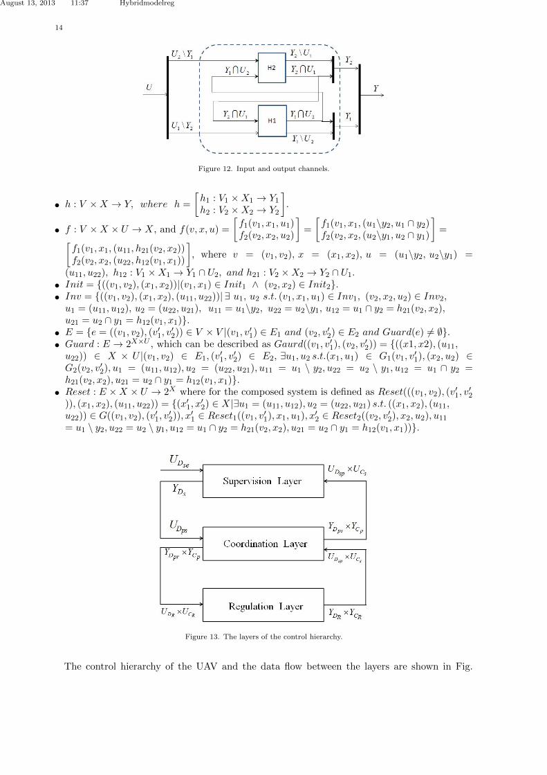
• V = V1 ⇥ V2 and X = X1 ⇥X2.• U = (U1 \ Y2)⇥ (U2 \ Y1) and Y = Y1 ⇥ Y2 (See Fig. 12).
August 13, 2013 11:37 Hybridmodelreg
14
Figure 12. Input and output channels.
• h : V ⇥X ! Y, where h =
h1 : V1 ⇥X1 ! Y1h2 : V2 ⇥X2 ! Y2
�.
• f : V ⇥X ⇥ U ! X, and f(v, x, u) =
f1(v1, x1, u1)f2(v2, x2, u2)
�=
f1(v1, x1, (u1\y2, u1 \ y2)f2(v2, x2, (u2\y1, u2 \ y1)
�=
f1(v1, x1, (u11, h21(v2, x2))f2(v2, x2, (u22, h12(v1, x1))
�, where v = (v1, v2), x = (x1, x2), u = (u1\y2, u2\y1) =
(u11, u22), h12 : V1 ⇥X1 ! Y1 \ U2, and h21 : V2 ⇥X2 ! Y2 \ U1.
• Init = {((v1, v2), (x1, x2))|(v1, x1) 2 Init1 ^ (v2, x2) 2 Init2}.• Inv = {((v1, v2), (x1, x2), (u11, u22))| 9 u1, u2 s.t. (v1, x1, u1) 2 Inv1, (v2, x2, u2) 2 Inv2,
u1 = (u11, u12), u2 = (u22, u21), u11 = u1\y2, u22 = u2\y1, u12 = u1 \ y2 = h21(v2, x2),u21 = u2 \ y1 = h12(v1, x1)}.
• E = {e = ((v1, v2), (v01, v02)) 2 V ⇥ V |(v1, v01) 2 E1 and (v2, v02) 2 E2 and Guard(e) 6= ;}.
• Guard : E ! 2X⇥U , which can be described as Gaurd((v1, v01), (v2, v02)) = {((x1, x2), (u11,
u22)) 2 X ⇥ U |(v1, v2) 2 E1, (v01, v02) 2 E2, 9u1, u2 s.t.(x1, u1) 2 G1(v1, v01), (x2, u2) 2
G2(v2, v02), u1 = (u11, u12), u2 = (u22, u21), u11 = u1 \ y2, u22 = u2 \ y1, u12 = u1 \ y2 =h21(v2, x2), u21 = u2 \ y1 = h12(v1, x1)}.
• Reset : E ⇥X ⇥ U ! 2X where for the composed system is defined as Reset(((v1, v2), (v01, v02
)), (x1, x2), (u11, u22)) = {(x01, x02) 2 X|9u1 = (u11, u12), u2 = (u22, u21) s.t. ((x1, x2), (u11,u22)) 2 G((v1, v2), (v01, v
02)), x
01 2 Reset1((v1, v01), x1, u1), x
02 2 Reset2((v2, v02), x2, u2), u11
= u1 \ y2, u22 = u2 \ y1, u12 = u1 \ y2 = h21(v2, x2), u21 = u2 \ y1 = h12(v1, x1))}.
Figure 13. The layers of the control hierarchy.
The control hierarchy of the UAV and the data flow between the layers are shown in Fig.
August 13, 2013 11:37 Hybridmodelreg
15
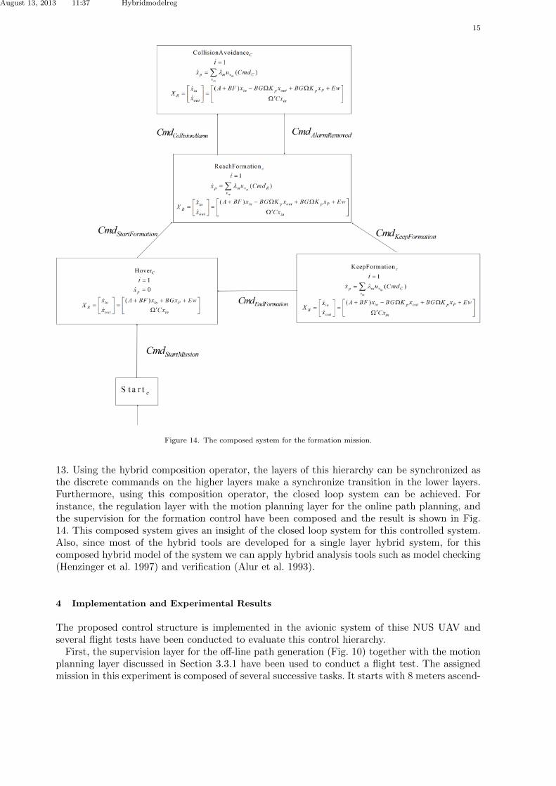
Figure 14. The composed system for the formation mission.
13. Using the hybrid composition operator, the layers of this hierarchy can be synchronized asthe discrete commands on the higher layers make a synchronize transition in the lower layers.Furthermore, using this composition operator, the closed loop system can be achieved. Forinstance, the regulation layer with the motion planning layer for the online path planning, andthe supervision for the formation control have been composed and the result is shown in Fig.14. This composed system gives an insight of the closed loop system for this controlled system.Also, since most of the hybrid tools are developed for a single layer hybrid system, for thiscomposed hybrid model of the system we can apply hybrid analysis tools such as model checking(Henzinger et al. 1997) and verification (Alur et al. 1993).
4 Implementation and Experimental Results
The proposed control structure is implemented in the avionic system of thise NUS UAV andseveral flight tests have been conducted to evaluate this control hierarchy.First, the supervision layer for the o↵-line path generation (Fig. 10) together with the motion
planning layer discussed in Section 3.3.1 have been used to conduct a flight test. The assignedmission in this experiment is composed of several successive tasks. It starts with 8 meters ascend-

August 13, 2013 11:37 Hybridmodelreg
16
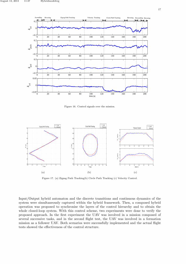
ing, followed by hovering, zigzag path tracking, velocity control, circle path tracking, hovering,and 8 meters descending. The mission ends with hovering. The state variables of the UAV areshown in Fig. 15. The control signals recorded in the flight test are shown in Fig. 16. To have abetter sense of the system performance, the reference signals and actual flight test data in ZigzagPath Tracking, Velocity Control, and Circle Path Tracking modes are presented in Fig. 18. As itcan be seen in this figure, the system is able to follow the given trajectory. Small deviations fromthe reference path could be due to the wind disturbances (around 2 to 3 m/s in the horizontalplane) and GPS signal errors as the position accuracy of GPS is 3m CEP. The video of thisflight test is available at http://uav.ece.nus.edu.sg/video/hybridswitching2.avi.
0 20 40 60 80 100 120 140 160 180 200
0
100
200
Posi
tion
(m)
x
y
z
0 20 40 60 80 100 120 140 160 180 200
−2
0
2
4
Vel
oci
ty (
m/s
)
V
x
Vy
Vz
0 20 40 60 80 100 120 140 160 180 200−4
−2
0
2
4
Angula
r
posi
tion
(rad
)
φ
θ
ψ
0 20 40 60 80 100 120 140 160 180 200−0.5
0
0.5
Time (s)
Angula
r vel
oci
ty (
rad/s
)
ω
x
ωy
ωz
HoveringCircle Path TrackingHovering DescendingAscending Velocity Line Tracking HoveringZigzag Path Trackin
Figure 15. State variables of the UAV.
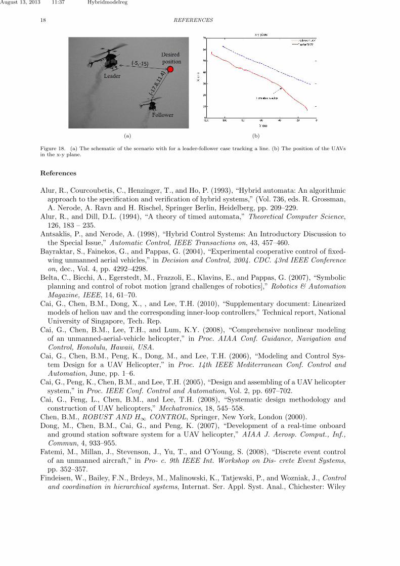
In the second experiment, we have implemented this control hierarchy in the avionic systemof a follower UAV which is involved in a formation mission. For this experiment, we have usedthe supervision layer and the motion planning layer shown in Fig. 9 and 11, respectively. In thisexperiment, the leader follows a line path and the follower should reach and keep the formation.The follower is initially located at a point that has a relative distance of (dx, dy) = (�17.8, 11.4)with respect to the desired position. Starting form a hovering mode, then the leader issues thestart command, and after 17 Sec, the follower reaches the formation that has a relative distanceof (dx, dy) = (-5, -15) with respect to the leader (Fig. 18(a)). The position of both followerUAV and the leader UAV are shown in Fig. 18(b). The video of this flight test is available athttp://uav.ece.nus.edu.sg/video/hybridswitching2.avi.
5 Conclusion
In this paper we developed a hierarchical hybrid control structure for a UAV helicopter. Thishierarchy consists of three layers: the regulation layer, which is responsible for reference tracking;the motion planning layer, which is responsible for the path planning, and the supervision layer,which is responsible for the task scheduling and decision making. Each layer was modelled by an
August 13, 2013 11:37 Hybridmodelreg
17
0 20 40 60 80 100 120 140 160 180 200−0.2
0
0.2
δro
l
0 20 40 60 80 100 120 140 160 180 200−0.2
0
0.2
δpit
ch
0 20 40 60 80 100 120 140 160 180 200−0.5
0
0.5
δped
0 20 40 60 80 100 120 140 160 180 200−0.05
0
0.05
δco
l
time (s)
DescendingHoveringCircle Path TrackingVelocity TrackingHovering Zigzag Path TrackingAscending Hovering
Figure 16. Control signals over the mission.
−20 −15 −10 −5 0 5 10 1510
20
30
40
50
60
70
80Zigzag Path Tracking
Y (m)
X (
m)
Actual
Reference
(a)
35 40 45 50 55 60 65 70 75 80160
165
170
175
180
185
190
195Circle Path Tracking
Y (m)
x (
m)
Actual
Reference
(b)
0 5 10 15 20 25 30 35−1
0
1
2
3
4
Vx (
m/s
)
0 5 10 15 20 25 30 35−1
0
1
2
3
4
Vy(m
/s)
Velocity Control
time (s)
Actual
Reference
(c)
Figure 17. (a) Zigzag Path Tracking(b) Circle Path Tracking (c) Velocity Control.
Input/Output hybrid automaton and the discrete transitions and continuous dynamics of thesystem were simultaneously captured within the hybrid framework. Then, a composed hybridoperation was proposed to synchronise the layers of the control hierarchy and to obtain thewhole closed-loop system. With this control scheme, two experiments were done to verify theproposed approach. In the first experiment the UAV was involved in a mission composed ofseveral successive tasks, and in the second flight test, the UAV was involved in a formationmission as a follower UAV. Both scenarios were successfully implemented and the actual flighttests showed the e↵ectiveness of the control structure.
August 13, 2013 11:37 Hybridmodelreg
18 REFERENCES
(a) (b)
Figure 18. (a) The schematic of the scenario with for a leader-follower case tracking a line. (b) The position of the UAVsin the x-y plane.
References
Alur, R., Courcoubetis, C., Henzinger, T., and Ho, P. (1993), “Hybrid automata: An algorithmicapproach to the specification and verification of hybrid systems,” (Vol. 736, eds. R. Grossman,A. Nerode, A. Ravn and H. Rischel, Springer Berlin, Heidelberg, pp. 209–229.
Alur, R., and Dill, D.L. (1994), “A theory of timed automata,” Theoretical Computer Science,126, 183 – 235.
Antsaklis, P., and Nerode, A. (1998), “Hybrid Control Systems: An Introductory Discussion tothe Special Issue,” Automatic Control, IEEE Transactions on, 43, 457–460.
Bayraktar, S., Fainekos, G., and Pappas, G. (2004), “Experimental cooperative control of fixed-wing unmanned aerial vehicles,” in Decision and Control, 2004. CDC. 43rd IEEE Conferenceon, dec., Vol. 4, pp. 4292–4298.
Belta, C., Bicchi, A., Egerstedt, M., Frazzoli, E., Klavins, E., and Pappas, G. (2007), “Symbolicplanning and control of robot motion [grand challenges of robotics],” Robotics & AutomationMagazine, IEEE, 14, 61–70.
Cai, G., Chen, B.M., Dong, X., , and Lee, T.H. (2010), “Supplementary document: Linearizedmodels of helion uav and the corresponding inner-loop controllers,” Technical report, NationalUniversity of Singapore, Tech. Rep.
Cai, G., Chen, B.M., Lee, T.H., and Lum, K.Y. (2008), “Comprehensive nonlinear modelingof an unmanned-aerial-vehicle helicopter,” in Proc. AIAA Conf. Guidance, Navigation andControl, Honolulu, Hawaii, USA.
Cai, G., Chen, B.M., Peng, K., Dong, M., and Lee, T.H. (2006), “Modeling and Control Sys-tem Design for a UAV Helicopter,” in Proc. 14th IEEE Mediterranean Conf. Control andAutomation, June, pp. 1–6.
Cai, G., Peng, K., Chen, B.M., and Lee, T.H. (2005), “Design and assembling of a UAV helicoptersystem,” in Proc. IEEE Conf. Control and Automation, Vol. 2, pp. 697–702.
Cai, G., Feng, L., Chen, B.M., and Lee, T.H. (2008), “Systematic design methodology andconstruction of UAV helicopters,” Mechatronics, 18, 545–558.
Chen, B.M., ROBUST AND H1 CONTROL, Springer, New York, London (2000).Dong, M., Chen, B.M., Cai, G., and Peng, K. (2007), “Development of a real-time onboardand ground station software system for a UAV helicopter,” AIAA J. Aerosp. Comput., Inf.,Commun, 4, 933–955.
Fatemi, M., Millan, J., Stevenson, J., Yu, T., and O’Young, S. (2008), “Discrete event controlof an unmanned aircraft,” in Pro- c. 9th IEEE Int. Workshop on Dis- crete Event Systems,pp. 352–357.
Findeisen, W., Bailey, F.N., Brdeys, M., Malinowski, K., Tatjewski, P., and Wozniak, J., Controland coordination in hierarchical systems, Internat. Ser. Appl. Syst. Anal., Chichester: Wiley
August 13, 2013 11:37 Hybridmodelreg
REFERENCES 19
(1980).Frazzoli, E., Dahleh, M., and Feron, E. (2000), “Robust hybrid control for autonomous vehiclemotion planning,” in Proc. 39th IEEE Conf. Decision and Control, Vol. 1, pp. 821–826.
Gillula, J., Huang, H., Vitus, M., and Tomlin, C. (2010), “Design of guaranteed safe maneuversusing reachable sets: Autonomous quadrotor aerobatics in theory and practice,” in Proc. IEEEConf. Robotics and Automation, May, pp. 1649–1654.
Henzinger, T.A., Ho, P.H., and Wong-Toi, H. (1997), “HYTECH: amodel checker for hybridsystems,” International Journal on Software Tools for Technology Transfer (STTT), 1, 110–122, 10.1007/s100090050008.
Johansson, K.H., “Introduction to hybrid systems,” Lecture notes, Department of Signals, Sen-sors and Systems. Royal Institute of Technology (2005).
Karimoddini, A., Cai, G., Chen, B., Lin, H., and Lee, T. (2011), Vol. Advances in Flight ControlSystems, “12,” Hierarchical control design of a UAV helicopter, INTECH, pp. 239–260.
Karimoddini, A., Cai, G., Chen, B., Lin, H., and Lee, T. (2010), “Multi-layer flight control syn-thesis and analysis of a small-scale UAV helicopter,” in Proc. IEEE Conf. Robotics Automationand Mechatronics, Jun., pp. 321–326.
Karimoddini, A., Dong, X., Cai, G., Feng, L., Lin, H., Chen, B.M., and Lee, T.H. (2011), “Acomposed hybrid structure for the autonomous flight control of unmanned helicopters,” in InProceedings of the 18th IFAC World Congress, Aug, pp. 2632–2637.
Karimoddini, A., Lin, H., Chen, B., and Lee, T.H. (2009), “Developments in hybrid modelingand control of Unmanned Aerial Vehicles,” in Proc. IEEE Conf. Control and Automation, pp.228–233.
Karimoddini, A., Lin, H., Chen, B.M., and Lee, T.H. (2012), “Hybrid three-dimensional forma-tion control for unmanned helicopters,” Automatica, 49, 424–433.
Latombe, J., Robot motion planning, Springer (1990).Liu, J., Liu, X., Koo, T., Sinopoli, B., Sastry, S., and Lee, E. (1999), “A hierarchical hybridsystem model and its simulation,” in Proc. 38th IEEE Conf. Decision and Control, Vol. 4, pp.3508–3513.
Lynch, N., Segala, R., and Vaandrager, F. (2001), “Hybrid I/O Automata Revisited,” in Proceed-ings Fourth International Workshop on Hybrid Systems: Computation and Control (HSCC’01,Springer-Verlag, pp. 403–417.
Lynch, N., Segala, R., and Vaandrager, F. (2003), “Hybrid I/O automata,” Information andComputation, 185, 105–157.
Mesarovic, M.D., Macko, D., and Takahara, Y., Theory of Hierarchical, Multilevel Systems,Vol. 68 of Mathematics in Science and Engineering, Academic Press (1970).
Naldi, R., Marconi, L., and Gentili, L. (2009), “Robust takeo↵ and landing for a class of aerialrobots,” in Proc. 48th IEEE conf. Decision and Control held jointly with 28th Chinese ControlConf. (CDC/CCC), pp. 3436–3441.
Ollero, A., and Merino, L. (2004), “Control and perception techniques for aerial robotics,”AnnualReviews in Control, 28, 167–178.
Peng, K., Cai, G., Chen, B.M., Dong, M., and Lee, T.H. (2006), “Comprehensive Modelingand Control of the Yaw Dynamics of a UAV Helicopter,” in Control Conference, CCC 2006.Chinese, aug., pp. 2087–2092.
Peng, K., Cai, G., Chen, B.M., Dong, M., Lum, K.Y., and Lee, T.H. (2009), “Design andimplementation of an autonomous flight control law for a UAV helicopter,” Automatica, 45,2333–2338.
Ramadge, P., and Wonham, W. (1989), “The control of discrete event systems,” Proceedings ofthe IEEE, 77, 81–98.
Rashid, S., and Lygeros, J., “Hybrid systems: modeling, analysis and control - open hybridautomata and composition,” Lecture notes, University of California at Berkley (1999).
Schouwenaars, T., Mettler, B., Feron, E., and How, J. (2003), “Hybrid Architecture for Full-Envelope Autonomous Rotorcraft Guidance,” in American Helicopter Society 59th Annual
August 13, 2013 11:37 Hybridmodelreg
20 REFERENCES
Forum, Arizona, May.Sobh, T., and Benhabib, B. (1997), “Discrete event and hybrid systems in robotics and automa-tion: an overview,” Robotics Automation Magazine, IEEE, 4, 16–19.


![A hybrid-hierarchical genome assembly strategy to sequence ...3 Genome assembly using a hybrid and hierarchical strategy The Jellyfish software [14] was used to count and determine](https://img.pdfslide.us/doc/110x75/60c177b0e958af3d90380270/a-hybrid-hierarchical-genome-assembly-strategy-to-sequence-3-genome-assembly.jpg)