Embed Size (px)
Citation preview
1
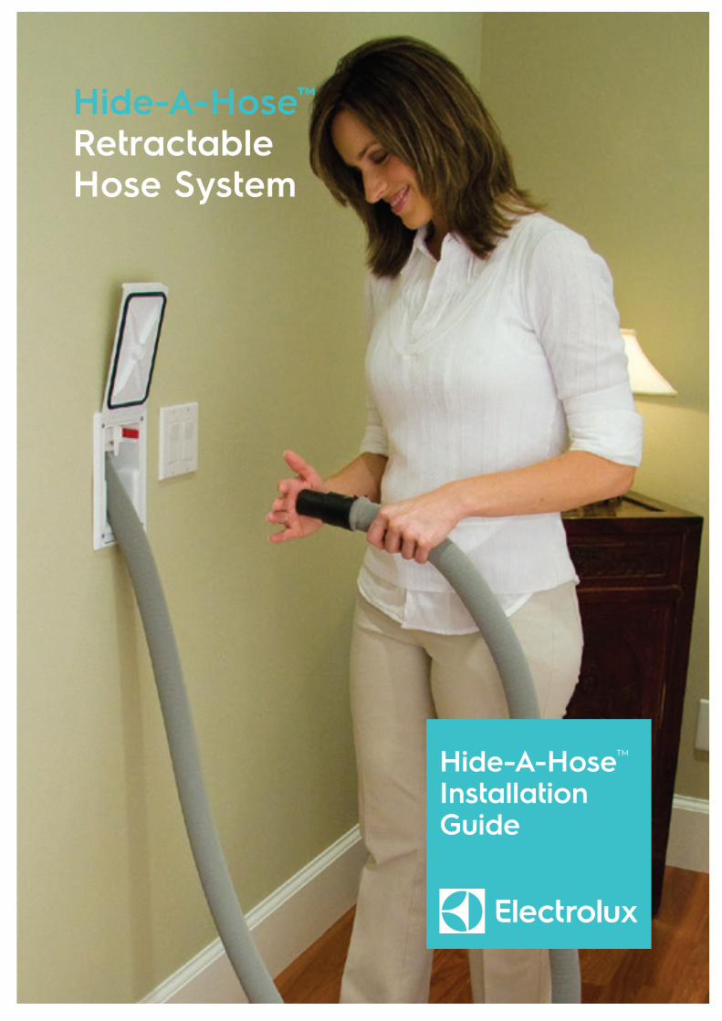
Hide-A-HoseTM
Installation Guide
Hide-A-Hose™
RetractableHose System
2
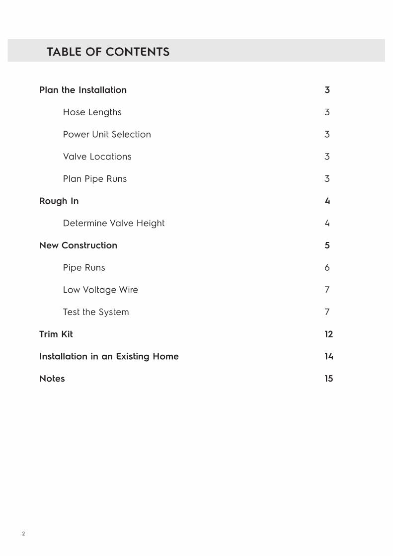
Plan the Installation 3 Hose Lengths 3 Power Unit Selection 3 Valve Locations 3
Plan Pipe Runs 3
Rough In 4
Determine Valve Height 4
New Construction 5
Pipe Runs 6
Low Voltage Wire 7
Test the System 7
Trim Kit 12
Installation in an Existing Home 14
Notes 15
TABLE OF CONTENTS
3
Warning
This manual is designed for installers with working knowledge and experience installing traditional central vacuum systems.
It is critical that only parts designed for the retractable hose system be used in the installation.
Parts include: screws, seals, washers, hoses, elbows (90’s, 45’s), etc.Failure to use these parts will void any warranty offered by the manufacturer.
Installers are responsible for adhering to all local building codes.
PLAN THE INSTALLATION
Planning is the key to a successful central vacuum system installation.A balance between the best locations for the inlet valves and practicalityof these locations is essential. With a little ingenuity most locations canbe reached.
Hose Lengths
Let clients know that you will custom the hose length to fit each floor.Hose kits come in 9, 12, 15, or 18 meter lengths.
Power Unit Selection
It is important to keep in mind that air flow is reduced with longer hoses.To compensate for the loss of air flow, a power unit with a minimum 650 Air Watts is required.
Valve Locations
A 18 m hose will usually cover a single floor up 215 square meters. Inlets should, if possible, be located in a hallway or in other areas that do not have high visibility.
Plan Pipe Runs
Carefully read the section in this guide on “Pipe Runs”. A diagram of fourtypical pipe runs is also available in this section.
4
Rough In Kit
Valve Assembly Door
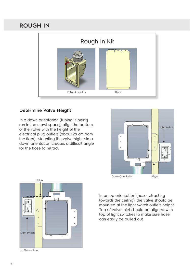
Determine Valve Height
In a down orientation (tubing is beingrun in the crawl space), align the bottomof the valve with the height of the electrical plug outlets (about 28 cm from the floor). Mounting the valve higher in a down orientation creates a difficult angle for the hose to retract.
ROUGH IN
In an up orientation (hose retractingtowards the ceiling), the valve should bemounted at the light switch outlets height.Top of valve inlet should be aligned withtop of light switches to make sure hosecan easily be pulled out.
Light Switch
AlignDown Orientation
Up Orientation
Align
Light Switch
5
NEW CONSTRUCTION
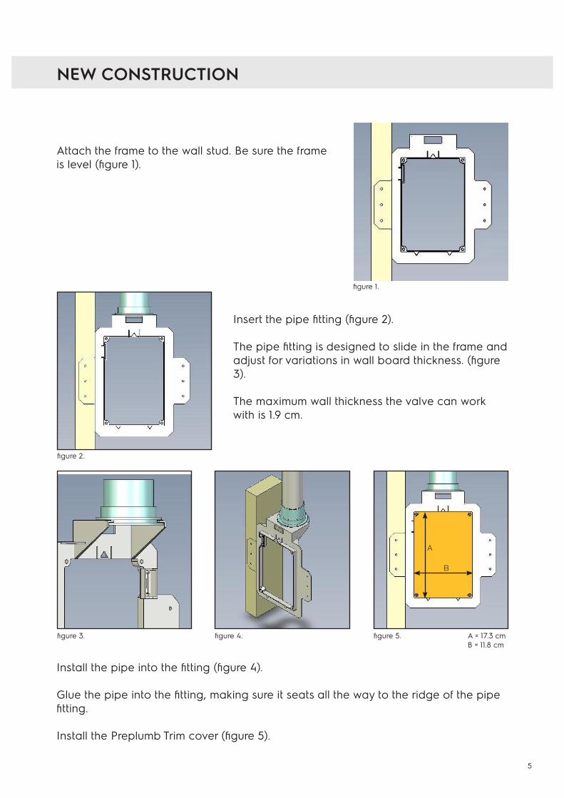
Attach the frame to the wall stud. Be sure the frame is level (figure 1).
Insert the pipe fitting (figure 2).
The pipe fitting is designed to slide in the frame and adjust for variations in wall board thickness. (figure 3).
The maximum wall thickness the valve can work with is 1.9 cm.
Install the pipe into the fitting (figure 4).
Glue the pipe into the fitting, making sure it seats all the way to the ridge of the pipe fitting.
Install the Preplumb Trim cover (figure 5).
figure 1.
figure 2.
figure 3. figure 4. figure 5. A = 17.3 cmB = 11.8 cm
A
B
6
Pipe Runs
Refer to the diagram on the next page.
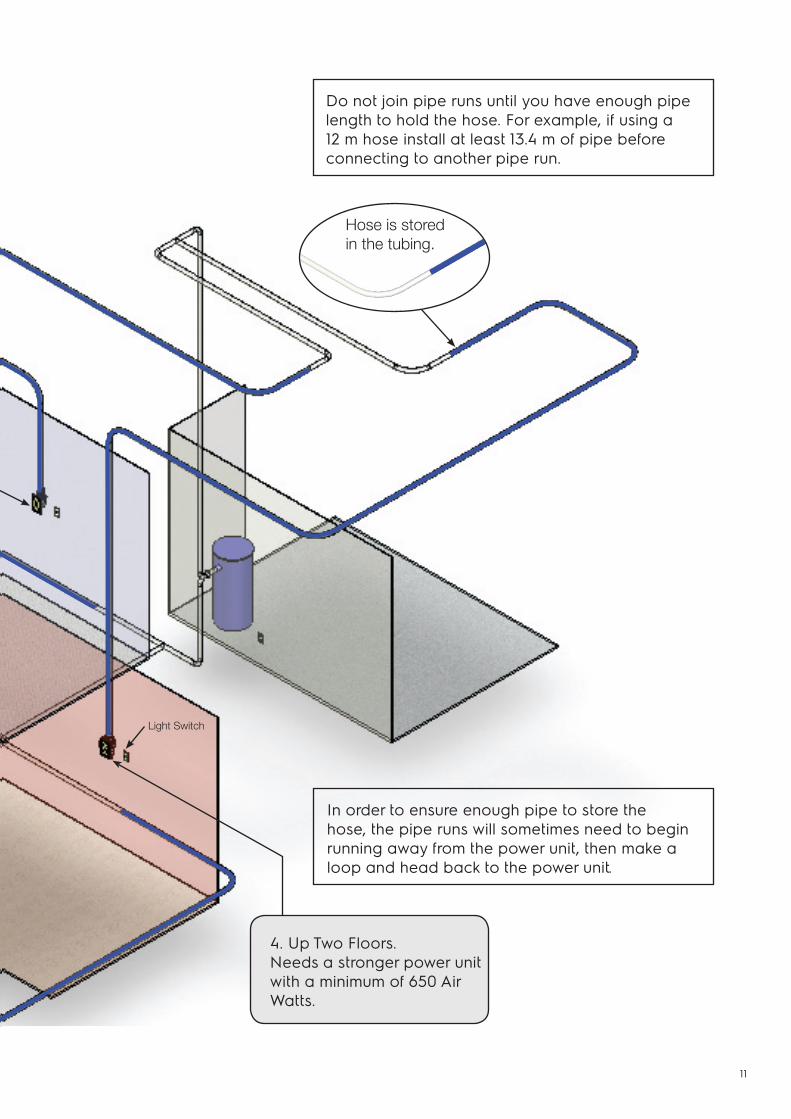
Do not join pipe run until you have enough pipe length to hold the hose. For example, if using a 12 m hose install at least 13.4 m of pipe before connecting to another pipe run.
In order to ensure enough pipe to store the hose, the pipe runs will sometimes need to begin running away from the power unit, then make a loop and head back to the power unit.
Any burr or excess glue glob can tear and damage the hose sock as it travels through the tubing. To prevent this, be sure to always glue the pipe and not the fittings. Make sure to remove all burrs from the pipe ends that were cut. Carefully inspect the pipe to make sure the inside is smooth and that the pipe is round and undamaged.
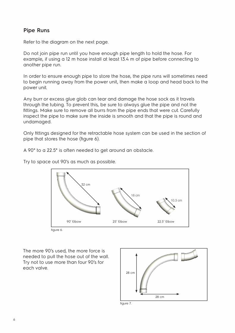
Only fittings designed for the retractable hose system can be used in the section of pipe that stores the hose (figure 6).
A 90° to a 22.5° is often needed to get around an obstacle.
Try to space out 90’s as much as possible.
The more 90’s used, the more force is needed to pull the hose out of the wall. Try not to use more than four 90’s for each valve.
90˚ Elbow
figure 6.
25˚ Elbow 22.5˚ Elbow
32 cm
18 cm
10.3 cm
figure 7.
28 cm
28 cm
7
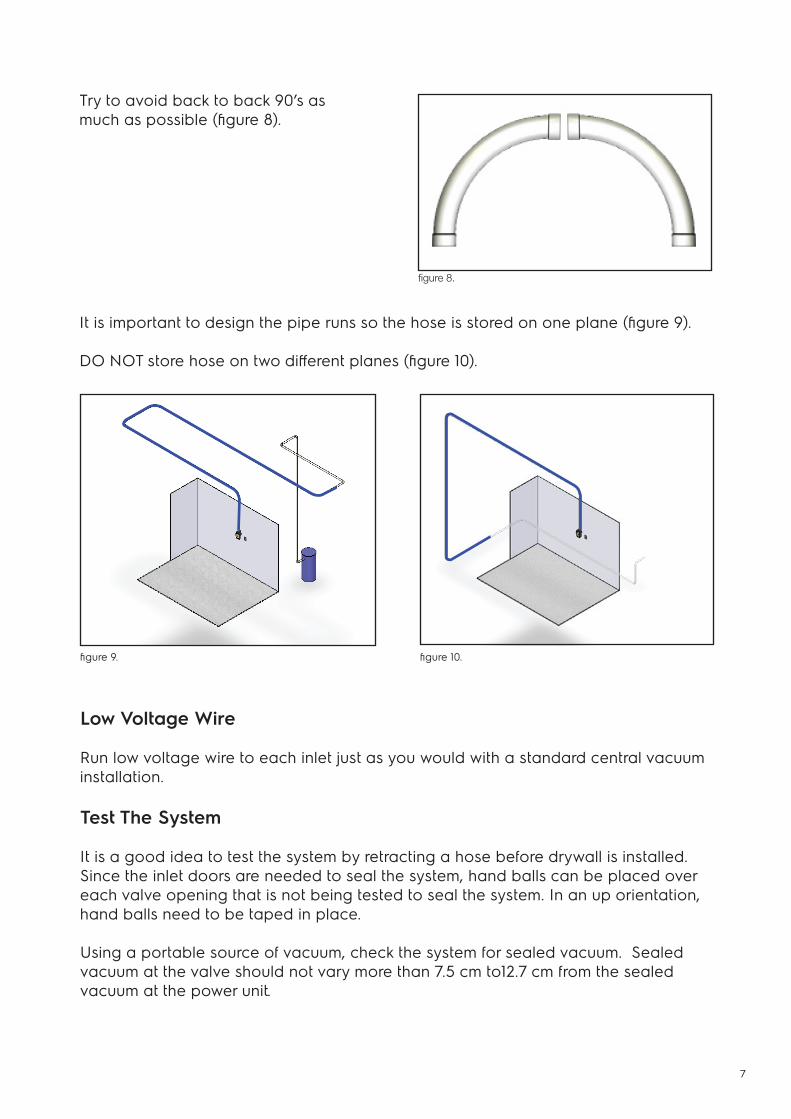
Try to avoid back to back 90’s asmuch as possible (figure 8).
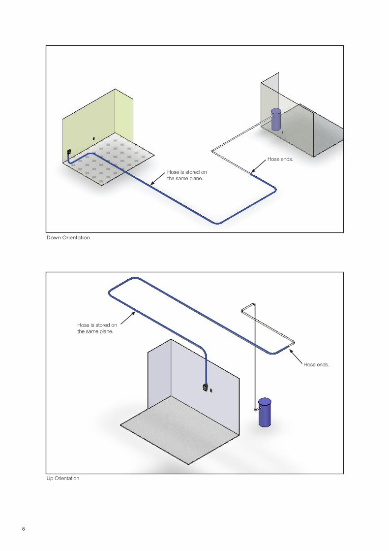
It is important to design the pipe runs so the hose is stored on one plane (figure 9).
DO NOT store hose on two different planes (figure 10).
Low Voltage Wire
Run low voltage wire to each inlet just as you would with a standard central vacuum installation.
Test The System
It is a good idea to test the system by retracting a hose before drywall is installed. Since the inlet doors are needed to seal the system, hand balls can be placed over each valve opening that is not being tested to seal the system. In an up orientation, hand balls need to be taped in place.
Using a portable source of vacuum, check the system for sealed vacuum. Sealed vacuum at the valve should not vary more than 7.5 cm to12.7 cm from the sealed vacuum at the power unit.
figure 8.
figure 9. figure 10.
8
Down Orientation
Hose is stored onthe same plane.
Hose ends.
Hose is stored onthe same plane.
Hose ends.
Up Orientation
9
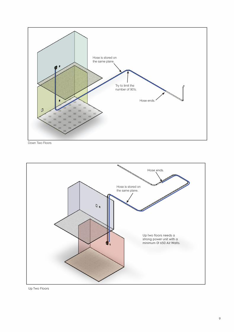
Up Two Floors
Hose is stored onthe same plane.
Up two floors needs a strong power unit with a minimum 0f 650 Air Watts.
Hose ends.
Down Two Floors
Hose is stored onthe same plane.
Try to limit the number of 90’s.
Hose ends.
10
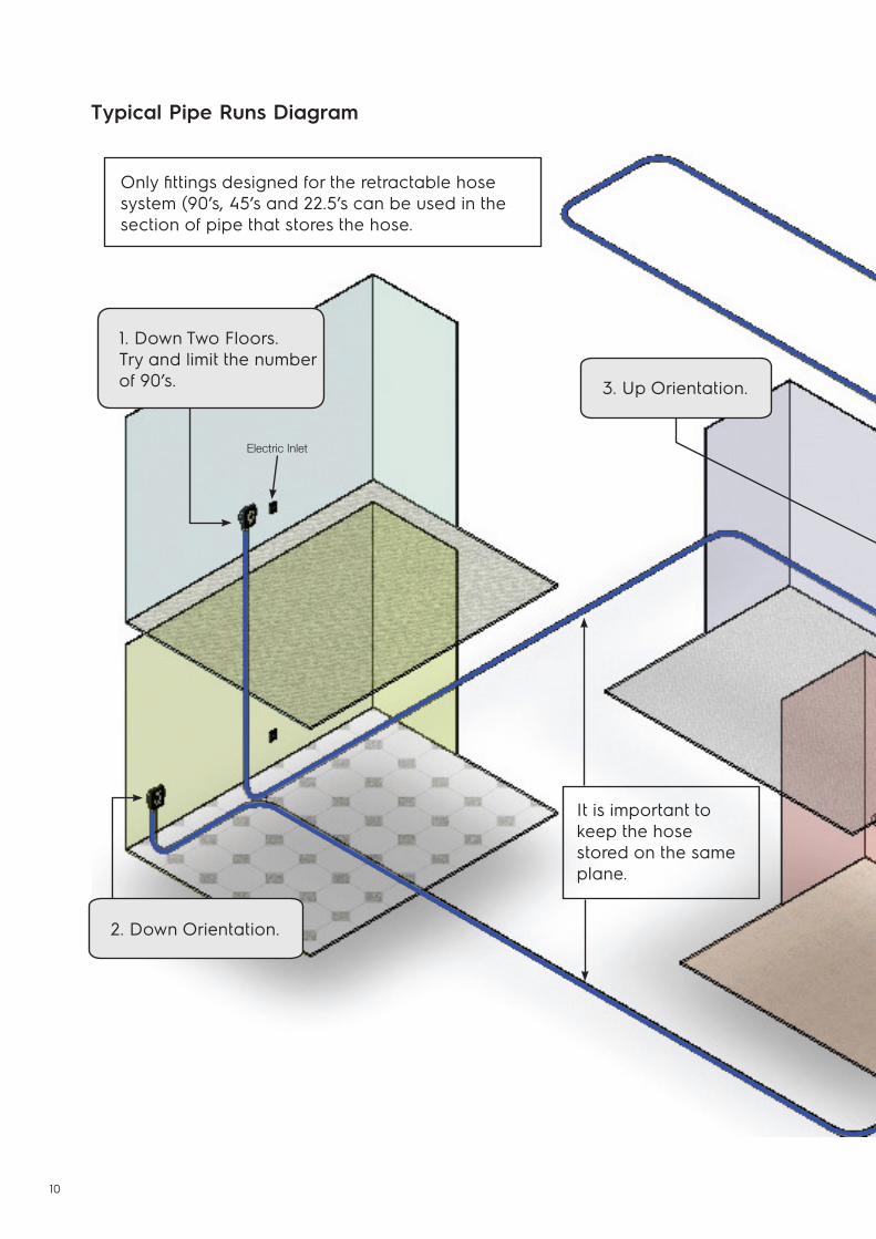
Typical Pipe Runs Diagram
Only fittings designed for the retractable hose system (90’s, 45’s and 22.5’s can be used in the section of pipe that stores the hose.
1. Down Two Floors.Try and limit the numberof 90’s.
2. Down Orientation.
3. Up Orientation.
It is important to keep the hose stored on the same plane.
Electric Inlet
11
Do not join pipe runs until you have enough pipe length to hold the hose. For example, if using a 12 m hose install at least 13.4 m of pipe before connecting to another pipe run.
In order to ensure enough pipe to store the hose, the pipe runs will sometimes need to begin running away from the power unit, then make a loop and head back to the power unit.
4. Up Two Floors.Needs a stronger power unit with a minimum of 650 Air Watts.
Light Switch
Hose is stored in the tubing.
12
TRIM KIT
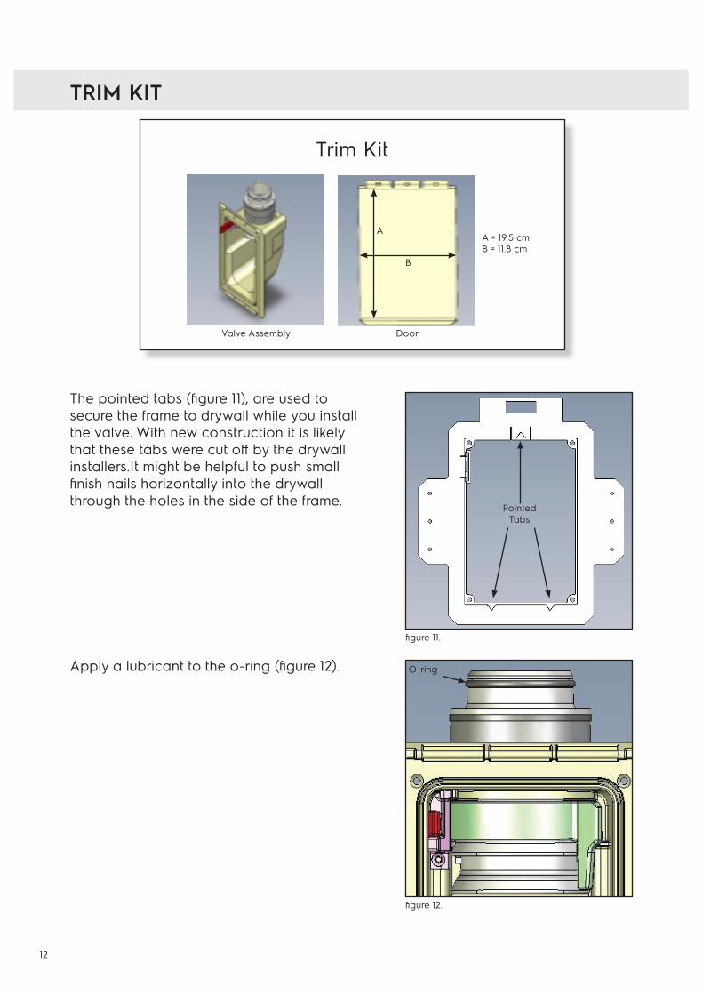
The pointed tabs (figure 11), are used to secure the frame to drywall while you install the valve. With new construction it is likely that these tabs were cut off by the drywall installers.It might be helpful to push small finish nails horizontally into the drywall through the holes in the side of the frame.
Apply a lubricant to the o-ring (figure 12).
Trim Kit
Valve Assembly Door
A = 19.5 cmB = 11.8 cm
A
B
figure 11.
figure 12.
Pointed Tabs
O-ring
13
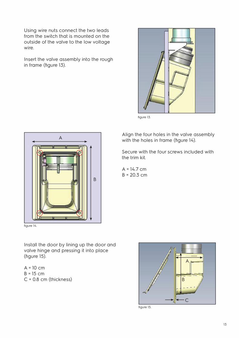
Using wire nuts connect the two leads from the switch that is mounted on the outside of the valve to the low voltage wire.
Insert the valve assembly into the rough in frame (figure 13).
Align the four holes in the valve assemblywith the holes in frame (figure 14).
Secure with the four screws included with the trim kit.
A = 14.7 cmB = 20.3 cm
Install the door by lining up the door andvalve hinge and pressing it into place (figure 15).
A = 10 cm B = 15 cmC = 0.8 cm (thickness)
figure 13.
figure 15.
figure 14.
A
A
B
C
B

14
Use the preplumb trim as a template to cutthe hole (figure 16).
Push the bottom two pointed tabs into the drywall (figure 18). The top pointed tab can be bent down as you pull the top of the frame into the hole. The tabs will help hold the frame into place while you install the valve. You may need to push a couple of small finish nails horizontally into theholes located on the side of the frame.
Follow the same instructions for installing the pipe runs and trim.
Insert the rough in frame vertically, then turn it back upright behind the wall (figure 17).
Depending on how close you are to a wall stud, you may need to score and cut off one or both of the mounting tabs.
INSTALLATION IN EXISTING HOME
figure 16.
figure 17.
figure 18.
15
NOTES:

16
© 2
015
Elec
trolu
x C
entra
l Vac
uum
Sys
tem
s
Distributed by:
Electrolux Central Vacuum Systems5855 Terry Fox WayMississauga, ON L5V 3E4Canada
beamvac.comelectroluxcentralvac.com