Embed Size (px)
Citation preview
COMMUNICATIONS ANDINFORMATION HANDLING
HICOM CONTROL TERMINAL
INTERFACE SPECIFICATION
7711-100-50050
PM -1464
Copyright© 1977By Harris CorporationAll Rights Reserved

COMMUNICATIONS ANDRI SV INFORMATION HANDLING
WARRANTY
Harris Corporation/RF Communications Div. warrants the equipment purchased hereunderto be free from defects in material and workmanship under normal use and service when usedfor the purpose for which the same is designed, for a period of one year from date of receipt,provided that notice of such defect is given to RF Communications or its authorized servicedepot, within 60 days after discovery thereof and provided that inspection by RF Commu-nications or its authorized service depot, indicates the parts are defective to RF Communi-cations' reasonable satisfaction. RF Communications' obligations under this warranty arelimited to the repair or replacement of defective parts and the return of such repaired orreplaced parts to the purchaser F.O.B. Factory. At RF Communications' option, any defectivepart shall be returned to RF Communications' factory for inspection, properly packed and allexpenses prepaid. No parts shall be returned unless the purchaser first obtains a return authori-zation number, which will be furnished on request. No warranties other than those set forthin this section are given or are to be implied with respect to the equipment furnished here-under and Harris Corporation/RF Communications Div. shall in no event be liable for conse-quential damages, or for loss, damage or expense directly or indirectly arising from the use ofthe products, in combinationequipment or materials, or from any other cause.
NOTECertain fixed price repair charges may be established byHarris Corporation/RF Communications Div. with authori-zed service depots providing for labor coverage during thewarranty period. The customer is advised to ascertain thesecharges from his dealer at the time of purchase.
CORRESPONDENCE AND PARTS ORDERING
Whenever writing about this unit or ordering parts, always refer to the model and serial num-bers and the approximate date of purchase. Special parts should be ordered by the RF partnumber and the schematic designation number. Standard parts can be obtained from yourlocal parts distributor.
RETURN OF EQUIPMENT
No equipment or part thereof shall be returned to Harris Corporation/RF CommunicationsDiv. unless the purchaser first obtains a return merchandise number from RF Communications.This number is to be marked on the shipping container. Equipment should be returned toHarris Corporation/RF Communications, 1680 University Avenue, Rochester, New York14610 USA.

COMMUNICATIONS ANDINFORMATION HANDLING
HICOM CONTROL TERMINAL
INTERFACE SPECIFICATION
Revised November, 1976.
This specification reflects characteristics of equipment
described in the System Requirements and Description
segment. It may not apply in all details to specific
configurations as described in Section 1.0 of that
segment, but applies where required for the equipment
to be delivered.
HARRIS CORPORATION RF COMMUNICATIONS DIVISION 1680 University Avenue, Rochester, N.Y. 14610 U.S.A.Phone 716-244-5830 Cable: RFCOM: Rochester, N.Y. TWX 510-253-7469 TELEX 978464
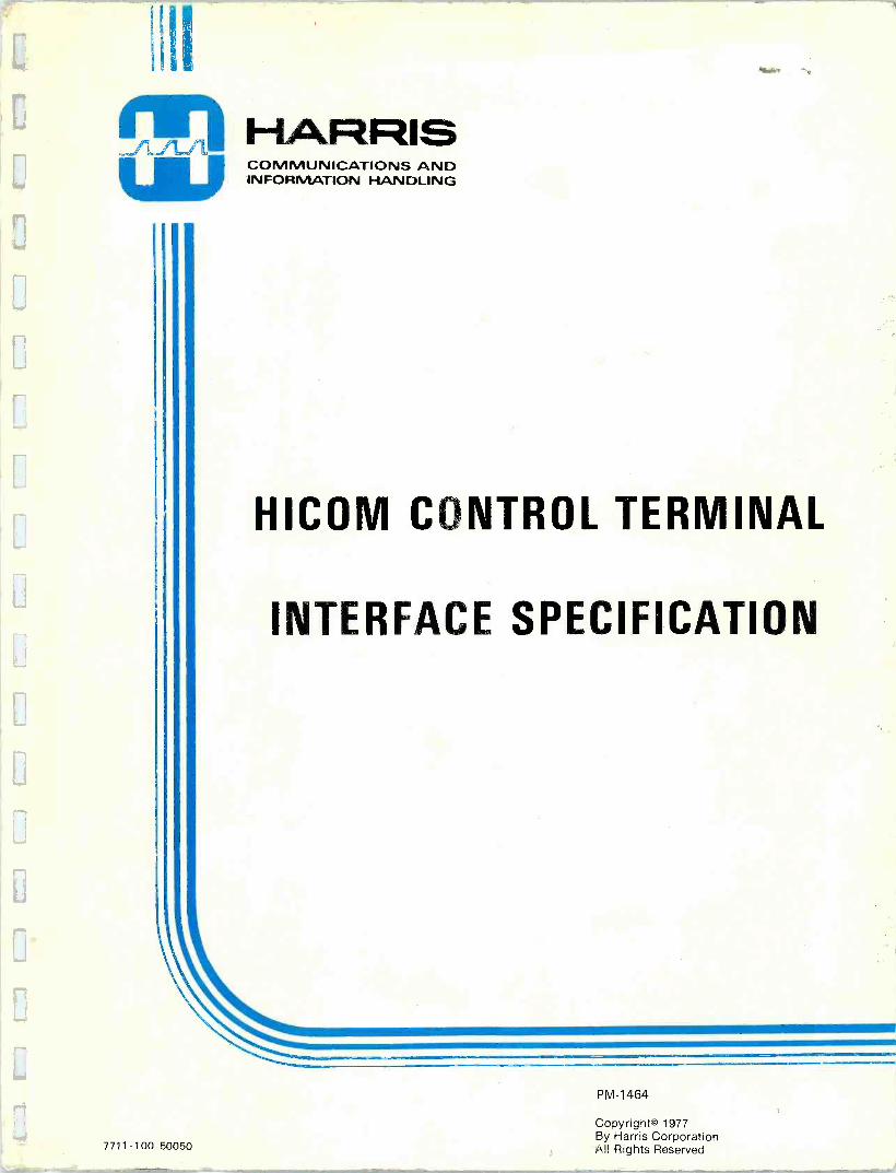
Interface Specification Contents
1.0 Introduction 1
2.0 Mobile Unit Tone Signaling Interface 2
2.1 Mobile -to -Land, Land -to -Mobile and Mobile -to -Mobile
Signaling Tones 2
2.2 Subscriber Directories 7
2.3 Validation Checks 7
2.4 Service to Roamers 7
2.5 Mobile Unit Busy Checks 8
2.6 Numbering Plan 9
2.7 Direct Distance Dialing 9
2.8 Billing and Traffic Measurements 10
3.0 Control Terminal to Central Office Interface
3.1 Trunk Interface
4.0 Control Terminal to Base Station Interface
4.1 Line Characteristics
4.2 Signal Characteristics
11
11
32
33
33
5.0 Control Terminal Physical Interface 38
5.1 Packaging Configuration 38
5.2 Weights and Floor Loading 39
5.3 Environment 39
5.4 Power Requirements 40
5.5 Safety Features 41
6.0 Man -Machine Interface 42
6.1 System/Operator Interface 42
7.0 Magnetic Tape Output 50
8.0 Maintenance Interface 60
9.0 Voice Announcement Recorder Unit Audio Input Interface 63
ii

1.0 INTRODUCTION
This specification defines the functional and operational inter-
faces of the Harris/RF Communications HICOM Control Terminal and
ancillary equipment. The Control Terminal performs the function
of interconnecting IMTS mobile radio telephones with the public
switched telephone network. All call processing, data recording,
equipment switching, and remote system hardware are under
control of a stored program processor in the Control Terminal.
The points of interface covered by this specification are: the
mobile unit through its signaling sequence; the trunks to the
Central Offices and Mobile Service Operator positions; the
interconnecting facilities to the transmitters and receivers
of the base stations; the size, weight, power and environmental
requirements; man -machine; magnetic tape data formats; maintenance;
and announcement recorder and reproducer. Unless specified, all
impedance measurements and frequency response data are referenced
to 1000 Hz.

2.0 MOBILE UNIT TONE SIGNALING INTERFACE
This section describes the tone parameters and sequences for thesupervisory signaling over the radio channels between the Mobile Unitsand the system Base Station transmitter and receivers.
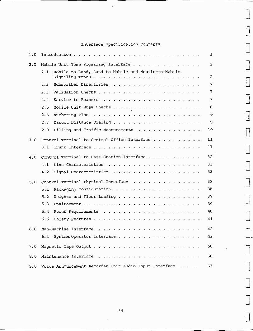
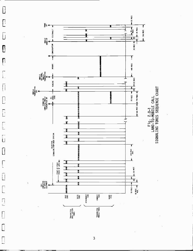
The signaling performed on the land -to -mobile and mobile -to -land RFlinks is defined in Figures 2.0-1 and 2.0-2. The detailed requirementsof the signaling sequence are given in the following paragraphs.
2.1 Mobile -to -Land, Land -to -Mobile and Mobile to Mobile SignalingTones
Five audio frequency tones are used for all supervisory signalingto and from the Mobile Units. Downlink tones (Control Terminal to Mobile)are idle, 2000 + 5 Hz, and seize, 1800 + 5 Hz. Uplink tones (mobiles toControl Terminal) are guard, 2150 + 25 Hz, connect, 1633 + 20 Hz and dis-connect, 1336 + 20 Hz.
2.1.1 Idle Tone
The Control Terminal generates a marked -idle signal designatingan available call channel. The Base Station transmits idle tone on anysingle channel to designate its use as the system call processing channel.
2.1.2 Idle Tone Removal Time
The Control Terminal recognizes the Mobile Unit's (MU) guard-connect tone sequence and removes idle tone within 37 msec of the beginningof the MU's connect -tone transmission.
2.1.3 Mobile -to -Land Connect Acknowledgment
After reception of the connect signal from an MU, the idle toneis removed for 300 msec, and then the seize tone is applied. The seizetone is held for a minimum of 50 msec.
2.1.4 ANI Reception Characteristics
2.1.4.1 ANI Start Delay Time
The Control Terminal measures the time between the end ofthe seize tone burst and receipt of the first Automatic Number Identifica-tion (ANI) pulse. If this time exceeds 1 second (including computer scantime) a reorder tone is returned to the MU for 30 seconds and the call isdisconnected.
2.1.4.2 ANI Digit Interval
The Control Terminal measures the time between reception ofeach ANI digit. If this time exceeds 1 second a reorder tone is returnedto the MU for 30 seconds and the call is disconnected.
2
I_ :
1(7
71[T
if
l 7
__!
-7
TR
AN
SM
ITT
ED
BA
SE
ST
AT
ION
TO
NE
S
TR
AN
SM
ITT
ED
MO
BIL
E T
ON
ES
IDL
E20
00
SE
IZE
1800
DIS
CO
NN
EC
T13
36
CO
NN
EC
T16
33
GU
AR
D
2150
CA
LLC
OM
PLE
TE
DT
O O
FF
ICE
EQ
UIP
ME
NT
V:~
///í3
ST
AR
T O
F F
IRS
TP
ULS
E O
F IM
TS
AN
I
114
SE
LEC
TIV
ES
IGN
ALI
NG
FR
OM
BA
SE
ST
AT
ION Pi
////
MO
BIL
ET
RA
NS
MIT
TE
RO
FF
SIG
NA
LIN
GC
OM
PLE
TE
D M
OB
ILE
TR
AN
SM
ITT
ER
ON
MO
BIL
E
OF
F -
HO
OF
,M
OB
ILE
TR
AN
SM
ITT
ER
MO
BIL
ET
RA
NS
ON
HA
NG
S U
PO
FF
AC
--
KN
OW
L--.
e-R
ING
ING
AN
SW
ER
-.
CO
NV
ER
SA
TIO
N r
DIS
CO
NN
EC
T-
ED
GE
4
A///
//////
/J7/
/íY.Y
//N///
////H
//////
.i////
.
50 M
SE
C
50 M
SE
CMIN. i
45 -
50 M
SE
C
250
MS
EC
MIN
.
//////
/.lM
INW
AI1
L190
MS
EC
25 M
SE
C
750
MS
EC
ÍM1
6lA
[m-2
5M
SE
C25
MS
EC
Fig. 2.0-1
LAND -TO -MOBILE CALL
SIGNALING TONES SEQUENCE -CHART
400
MS
EC
S
LEC5
s- 2
5 N
SE
C
r25
MS
EC
750
MS
EC

TR
AN
SMIT
TE
DB
ASE
STA
TIO
NT
ON
ES
TR
AN
SMIT
TE
DM
OB
ILE
TO
NE
S
IDL
E20
00
SEIZ
E18
00
DIS
CO
NN
EC
T13
36
CO
NN
EC
T16
33
WA
RD
2150
MO
BIL
E O
FF-M
OD
KT
RA
NSM
ITT
ER
ON
CO
NN
EC
T
/H///
///./a
STA
RT
IDE
NT
IFIC
AT
ION
é44
IDE
NT
IFIC
AT
ION
Nf
RE
CE
IVE
EN
DD
IAL
IDE
NT
IFIC
AT
ION
TO
NE
350
MSE
CL
5050
MSE
CM
SEC
-+
MIN
.".
.- 2
50 M
EG
-.M
IN.
190
MSE
C_.
i 190
MSE
CL
-i 1
90 M
SEC
25 M
SEC
25 M
SEC
Wfa
if
FIR
ST D
IGIT
.---
OFF
NO
RM
AL
CL
OSE
D
MO
BIL
EM
OB
ILE
CA
LL
HA
NG
ST
RA
NSM
ITT
ER
AN
SWE
RE
Dup
OFF
CO
NV
ER
SAT
ION
-+
...-
DIA
LIN
Gt D
ISC
ON
NE
CT
+
REMAINING
~ DIGITS
/4A
i
190
MSE
C
Fig. 2.0-2
MOBILE -TO-LAND CALL
SIGNALING TONES SEQUENCE CHART
50M
SEC
-.i
50 M
SEC
25 M
SEC
w
25 M
SEC
1 Y
6w
Nla a 25
MSE
C
25 M
SEC
t 25
MSE
C
w 7
50 M
SEC

2.1.4.3 ANI Parity Check
The Control Terminal checks parity of each ANI digit. Oncalls with bad parity a reorder tone is returned to the MU for 30 secondsand the call is disconnected.
2.1.4.4 ANI AddYss V, ification
The Control Terminal checks the received ANI address toverify that it is a home address or an authorized roamer. If the addressis acceptable the call is processed. If the address is not authorizedfor service, an announcement* is returned to the MU for 25 seconds and thecall is disconnected.
2.1.5 Dial Tone Acquisition
After receipt of the MU's ANI, the Control Terminal generatesdial tone and returns the dial tone to the MU.
2.1.6 Dial Pulse Acceptance
The Control Terminal accepts dial pulses at a nominal 10-ppsrate and 50 percent break and repeats these pulses to the Central Officewith proper pulse characteristics. The dial pulses from the MU willconsist of a 50 + 10 msec burst of connect tone with a 50 + 10 msec inter -pulse time of guard tone. An interdigit time of 600 msec minimum isrequired. The first digit must be received within 10 sec of the dialtone. If the interdigit time exceeds 10 sec the call will be disconnected.After dialing is completed, the Central Office is accessed by the ControlTerminal.
2.1.7 Land -to -Mobile Addressing
2.1.7.1 Seize Tone Prior to Addressing
The Control Terminal disconnects the idle tone and appliesthe seize tone for at least 300 msec prior to the first signaled digit pulse.
2.1.7.2 Addressing Pulse Characteristics
The Control Terminal provides dialing of mobile addressesat a nominal 10 + 0.5 pps and 50 + 10 percent break. The pulse ratedoes not vary beyond 10 * 1.5 pps and 50 + 3 percent break.
2.1.7.3 Address Interdigit Time
The addressing interdigit time is 300 msec + 25 mesc.
*All announcements are contingent on the HICOM Control Terminal beingequipped with the Voice Announcement Recorder option. If not, tones aresupplied in lieu of announcements.
5
2.1.7.4 NPA Addressing
The Control Terminal provides means of coding the firstthree digits of the called MU address such that any Numering Plan Area(NPA) code may be pulsed on outgoing calls.
2.1.8 Called MU Acknowledgment
2.1.8.1 Acknowledgment Reception
After dialing is complete, the Control Terminal providesthe seize tone until an acknowledge burst of guard tone is received fromthe MU. The Control Terminal is capable of recognizing an acknowledgeburst of 500 msec minimum duration.
2.1.8.2 Acknowledgment Failure
Up to 3 seconds is permitted for an MU to respond to itscalled address with an acknowldege burst. If the acknowledge is not re-ceived, the Control Terminal will cease processing that call andreturn a "CANNOT BE REACHED" voice announcement* to the calling party.
2.1.9 Ring Signal
If the acknowledge signal is received from the called MU theControl Terminal generates a ring signal of idle and seize tones alter-nating at a 20-pps rate with a 1 second on and 3 seconds off duty cycle.
2.1.10 Called MU Answer Characteristics
2.1.10.1 Answer Signal Reception
The Control Terminal accepts an answer tone consisting of287 msec (min.) of connect tone. Reception of the answer tone permitsconversation between the calling party and the called MU.
2.1.10.2 Unanswered Call
If the Control Terminal fails to receive an answer pulsewithin 45 seconds, the call is disconnected and the ringback signal tothe Central Office is inhibited and a "CANNOT BE REACHED" announcement*is sent to the calling party.
2.1.11 Call Disconnect Characteristics
2.1.11.1 Disconnect Signal
The Control Terminal accepts an MU originated disconnectsignal composed of alternating 25-msec pulses of guard and disconnecttones. The Control Terminal recognizes a disconnect signal of 500 msecminimum duration.
*All announcements are contingent on the HICOM Control Terminal beingequipped with the Voice Announcement Recorder option. If not, tones aresupplied in lieu of announcements.
6

2.2 Subscriber Directories
Complete listings of all valid home subscribers in the systemare maintained in a positive directory. Local NPA addresses which are tobe denied system access are omitted from the positive file directory.Foreign NPA addresses to be denied access to the system are listed in thenegative directory.
The positive file contains registry for up to 10,000 addresses in anyone area code (NPA). Random number assignment is provided eliminatingany requirement for block assignments. Where two or more NPA's are served,10,000 addresses are provided in each NPA.
The negative file is maintained strictly to deny access to specifiedaddresses, address groups, or foreign or home NPA's. The number of ad-dresses that may be contained in this file is a variable which is afunction of the system configuration.
2.3 Validation Checks
Prior to processing a call to or from a Mobile Unit, the ControlTerminal performs a validation test on the MU's address as dialed by thecalling party, or as received in the form of an ANI -from the MU. The testinvolves two memory files designated positive directory and negativedirectory.
MU users with a home NPA (defined as any or all NPA's within any oneterminal) are given service automatically if their number appears in thepositive directory. Service is denied to home NPA numbers not in thepositive directory with a "CANNOT BE SERVED" announcement* returned to thecaller if the number is listed in the negative directory. A "DISCONNECTED"announcement* is given if the number is not listed in either directory.
MU users with a foreign NPA (defined as a valid NPA that is differentfrom a home NPA) are also given service automatically if their number isnot in the negative directory. If their number is in the negative di-rectory, the caller is given a "CANNOT BE SERVED" announcement* on an at-tempted call.
If a call is placed via a roamer "trunk" (C.O. line) or by theMobile Service Operator, the NPA is checked for the form 'XOX' or 'X1X'.When the NPA is not of the proper form, reorder tone is given to thecalling party. When the NPA format is valid, a check is made of thenegative directory, and service is denied if the ANI is in the directory.
2.4 Service to Roamers
Roamers are MU's operating out of their area of registry andmay be called via the Touch Tone® (DTMF) roamer "trunk" or by accessingvia the Mobile Service Operator. Roamers listed in the negative fileare denied service.
*All announcements are contingent on the HICOM Control Terminal beingequipped with the Voice Announcement Recorder option. If not, tones aresupplied in lieu of announcements.
7
If a tone pair representing an asterisk (*) is received by theControl Terminal on a DTMF roamer "trunk," all previously dialed digitswill be ignored and the caller may immediately re -dial.
2.5 Mobile Unit Busy Checks
After the validation of an MU's number, a check is made to determineif the addressed MU is busy. For a land -to -mobile call, a busy checkis made only in the service area corresponding to the trunk being used.For mobile -to -land calls**, all channels are checked. (This is the"bandit" check.) On a land -to -mobile call, if the MU is busy, a busytone is returned to the calling party. On a mobile -to -land call**, ifthe MU's number is busy on another channel, an entry is made to thebilling record on the magnetic tape with the proper call class code, andthe "CANNOT BE SERVED" announcement* is returned to the MU.
*All announcements are contingent on the HICOM Control Terminal beingequipped with the Voice Announcement Recorder option. If not, tonesare supplied in lieu of announcements.
**Includes mobile -to -mobile calls.
8

2.6 Numbering Plan
The HICOM dial numbering plan uses a standard IMTS format, 4 digitsplus 3 digits for an area code (Numbering Plan Area). The full 7 -digit
plan permits service to be provided to roamers without ambiguity (withinan NPA) and standardizes the address formats from system to system. Each
subscriber within an NPA is identified by and responds to the uniqueaddress assigned to his MU. The address formats used in IMTS are as shown
below:
1 MU Automatic Number Identification (ANI)
NPA-XXXX
2 Land Address dialed by the MU user
NXX-XXXX (Local Exchange or Any Exchange in Local NPA)
or 1 - NPA-NXX-XXXX (Any Exchange)
3 MU's Received Address
NPA-XXXX
4 Mobile Service Operator Address
Any single - or multiple - digit address beginning with zero(0) .
On any mobile -to -land call, the Control Terminal checks the first andsecond digits to determine if 1, 3, 7, or 11 digits are to be dialed.Dialing to the output trunk is not initiated until all digits are receivedfrom the MU.
2.7 Direct Distance Dialing
Outgoing long distance calls from an MU can be dialed by the MobileService Operator or dialed direct by the calling user. Dual billing is,required: time charges on the HICOM system and time and distance charges
on the long distance network. Since the access to the DDD network normallyis through a trunk circuit to a toll switch from the Control Terminal(and not a subscriber loop as with a normal telephone), a means of auto-matic number identification (ANI) for the calling number is provided byHICOM for accounting purposes in the connecting telephone system.
9
2.8 Billing and Traffic Measurements
Call data are maintained for a history of every call that entersthe system including telephone numbers, equipment utilized, duration ofcall, etc. Class failure codes are assigned for all invalid and incompletecalls. The output is formatted for recording on IBM-compatible, 1600-cpimagnetic tape.
J
10
3.0 CONTROL TERMINAL TO CENTRAL OFFICE INTERFACE
The Control Terminal must be an integral part of the Mobile TelephoneSystem in order to meet its operational performance requirements. Thisis achieved through proper interface of the Control Terminal with techni-cal and service operators, and with such connecting equipment as CentralOffice* trunks, and Mobile Operator consoles. The following paragraphsspecify the Control Terminal to trunk line interface requirements. Theserequirements are taken from the "Technical Interface Criteria Related toDirect Inter -connection of Privately Owned PBX Systems to the PublicTelephone Network" document prepared by the FCC PBX Advisory CommitteeTechnical Standards Subcommittee, dated July 1972.
3.1 Trunk Interface
3.1.1 General
The Control Terminal (CT) operates with interconnectingCentral Offices (CO) over one-way incoming and one-way outgoing trunks.The trunk interface to the Mobile Operator console operates two-way,except no addressing is required from the CT to the operator position.
The trunks employ various methods of signaling and addressing, andoperate in various modes as delineated in this section. Where possible,the trunk interface circuits are designed to operate in multiple methodsand modes selectable by strapping or a similar technique. The inputtrunks óf each area controlled by the terminal may be isolated asrequired. The number and type of trunks that must be interfaced for eacharea will vary as a function of the system configuration. Figure 3.1-1shows the methods and modes of signaling in which the CT must operate.
For the purpose of the interface portion of this specification, theterm "trunk" is defined as a metallic pair designated "TIP" and "RING"unless otherwise specified. The point of interface with the TelephoneCompany's network is normally a terminal block furnished and installed bythe Telephone Company in a location near the Control Terminal. The trunkinterface circuits of the CT present a barrier to hazardous voltages andsignals that could otherwise be applied to the trunks, to the CO's, orto Mobile Operator consoles attributed to faults occurring within the CT.Figure 3.1-2 shows the trunk connections of the system.
3.1.2 Incoming Trunks
3.1.2.1 Direct Inward Dialing Trunks
An incoming trunk is defined as a trunk circuit that mayonly be seized by an off -hook signal initiated by the CO for the purposeof placing a call to a MU through the CT. The CT cannot transmit addresspulses over an incoming trunk, and can only signal "off -hook" on the trunk
*"Central Office" as used in this specification may refer to any connectingoffice and therefore the meaning is not restricted to "end offices" or"Class 5 offices."
11

IncomingTrunk
Intterface
OutgoingTrunk,
Interface
'
2 -Way
OperatorTrunk
- ...Interface..
From Operator To Operator.
SupervisorySignaling
AddressPulsing
AddressingMode
E&M
DP
MI'
WinkDelayBylink
ReverseBattery
DP
MF
WinkDelayBylink
GroundStart
DTMF
Bylink
E&M
DP
MF
WinkDelayBylink
ReverseBattery
DP
MF
WinkDelayBylink
MF .
E&M
jug
'DP
DelayBylink.
E&M
NoneRequired
NotApplicable
Figure 3.]-1. Trunk Interface Signaling Criteria
To Foreign1-12-411110
Co
To LocalCo
To MobileOperators
NOTE:
sltop
Directions ofArrow Heads onTrunks Indi-cate Directionof TrunkSeizure.
#2 to
#N .1_112.40.
to ñL CE
Incomin
TrunkInterface
Outgoing
Incoming
Outgoing
Incoming
Outgoing
Incoming
Outgoing
2 -Way
2 -Way
2 -Way
o
Processór
1:11'""
Data
i
Control
MATRIX
r
A
V
ChannelInterface
To local andforeign stations
Figure 3.1-2. Trunk Interconnection DiagramaControl Terminal
ControlTerminal
12

in response to the CO off -hook signal. An incoming trunk, therefore, hastwo-way supervisory (on -hook, off -hook) signaling, but always initiatedby the CO, and one-way address signaling generated by the CO.
Incoming trunks may employ either ground start, reversebattery or E&M supervisory signaling. The ground start trunks utilizeDTMF address pulsing; the reverse battery trunks utilize open -close cir-cuit address pulsing; while the E&M trunks use either open -close circuitor MF address pulsing. Open -close circuit pulsing is normally referredto as dial pulsing (DP) and consists of series of momentary on -hook,off -hook signals. The reverse battery trunks and E&M trunks operate ineither of three modes: wink start, delay dialing or by -link. The groundstart trunks operate in the by -link mode; however, a "go-ahead" signal issent to the calling party to indicate readiness to accept the called number.
Addressing received on the reverse battery and E&M trunksmay be either two or four "line assignment numbers" (digits) dependingupon the type of CO to be interfaced. Ten digits (NPA-XXX-XXXX) must bereceived on the ground start trunks to be properly processed.
The interface circuit clears or marks invalid partial ad-dresses when a subscriber fails to complete dialing in the alloted time.
Each incoming trunk interface circuit includes a green lightto indicate "busy" from time of trunk seizure until the trunk is releasedby the Control Terminal. The lights are observable from the front of theterminal.
3.1.3 Outgoing Trunks
3.1.3.1 Output to DDD Network
An outgoing trunk is defined as a trunk circuit that is seizedby an off -hook signal initiated by the CT for the purpose of placing a callthrough a connecting office (normally a toll switching facility such as aClass 4 office). An outgoing trunk therefore operates opposite to an in-coming trunk, having two-way supervision initiated only by the CT andone-way address signaling generated by the CT.
Outgoing trunks may employ reverse battery or E&M supervis-ory signaling and DP or MF addressing. The outgoing trunks are capableof operating in any one of the three modes: wink start, delay dialing, orby -link.
Each outgoing trunk interface circuit contains lamps toindicate when the trunk is in use, and when it is out of service as theresult of a fault. A green lamp is used to indicate busy, and a red lampis used to indicate out of service.
13

3.1.4 Two -Way Trunks
3.1.4.1 Mobile Service Operator Trunks
A two-way trunk is defined as a trunk circuit that is seizedby either the Control Terminal or the Mobile Service Operator (MSO). Thusthe two-way trunks have two-way supervisory signaling that is initiatedby either end. Address signaling on the operator trunk is only initiatedfrom the Mobile Service Operator console.
The two-way trunks utilize E&M supervision with either DP orMF addressing, but not both on the same trunk. The two-way operator trunksuse delay dialing.
Each two-way trunk interface circuit contains lamps to indi-cate when the trunk is in use, and when it is out of service as the resultof a fault. A green light is used to indicate the busy status, with ared light to indicate the trunk taken out of service by the Control Terminal.
3.1.5 Trunk Circuit Characteristics
The interconnection of the Control Terminal and the telephonecompany switched telephone network is in accordance with the followingparagraphs.
3.1.5.1 Hazardous Voltages and Currents
Voltages and currents in the telephone plant are consideredhazardous if levels exist of sufficient magnitude to imperil the safetyof telephone personnel, cause irreversible damage to telephone plant orequipment, or jeopardize reliable continuity of service. Of greatest con-cern are voltages and currents associated with or prodúced by powergenerating and distributing equipment, whether or not such equipment isa part of the HICOM Mobile Telephone System. As a consequence, compliancewith appropriate national and local ehectrical codes with respect to pro-tection of all exposed wiring and insftallation of AC power is required.
3.1.5.2 Maximum -Voltage Limits:) Steady -State Signals
The maximum permissible values of steady-state voltages,measured at the point of connection to telephone facilities are given inthe following paragraphs.
The barrier portion of the trunk interface circuitry is de-signed to insure that failures in the Control Terminal do not causesignals exceeding the limits of these paragraphs to be applied to thetelephone company side of the trunks.
3.1.5.2.1 The maximum permissible peak AC voltage between tip andring conductors may be 71 volts, except that 142 volts peak between thetwo conductors is permissible so long as the peak potential between eitherconductor and common ground does not exceed 71 volts.
14

3.1.5.2.2 The maximum permissible DC potential between tip and ring
conductors may be 135 volts, except that 270 volts DC is permissible so long
as the potential between either conductor and common ground does not
exceed 135 volts.
3.1.5.2.3 The maximum permissible DC potential between either con-
ductor and ground may be 135 volts.
3.1.5.2.4 For steady-state signals possessing both AC and DC com-
ponents, the maximum permissible composite peak potential between either
conductor and ground may be 71 volts.
3.1.5.2.5 For steady-state signals possessing both AC and DC com-
ponents, the maximum permissible peak potential between conductors may be
142 volts, so long as the peak potential between either conductor and
ground does not exceed 71 volts.
3.1.5.3 Maximum Current Limits
The maximum continuous current allowed to flow in either the
tip or the ring conductor on the Telephone Company side, whether AC, DC
or a composite of AC and DC, is 0.12 amperes rms. (The use of multiple
conductors to reduce the current per conductor is not permissible.)
3.1.5.4 Transient Voltage Limits
3.1.5.4.1 Relay Transients
Voltage transients incident upon the Telephone Company
side of the barrier interface (conductor to conductor, or conductor to
ground) resulting from release of relays in the Control Terminal may not
exceed 600 volts crest amplitude.
3.1.5.4.1.1 Relay release transients incident upon the interface
will decay to half crest amplitude within 2 ms.
3.1.5.4.2 Lightning and Power Surges
Transients at the interface resulting from lightning
strikes or power line crosses do not cause damage to the Control Terminal
under the following conditions:
3.1.5.4.2.1 Conductor -to -Conductor Surges:
Max. crest amplitude: 1000 volts
Rise time to crest: 10 microseconds (test specification)
Max, decay time to half crest: 1000 microseconds.
3.1.5.4.2.2 Conductor to ground surges:
Max. crest amplitude: 5000 volts
15

Rise time to crest: 1.2 microseconds (test specification)Max. decay time to half crest: 50 microseconds.
3.1.5.5 Signal Power
Excessive signal power injected into the switched telephonenetwork can result in increased noise and crosstalk levels, produce faultysignaling and supervision, or interfere with normal testing and maintenanceprograms. In general, signals considerably lower in level than those con-sidered "hazardous" will cause problems, with some frequency bands beingmore susceptible to harm than others. One consequence of this frequencydependency is the necessity for specifying distortion limits in the trans-mission path to control generation of harmonics of an acceptable signalthat may fail in a far more sensitive frequency band.
3.1.5.5.1 Talking Path Characteristics
3.1.5.5.1.1 Gain
The gain in the talking path from the channel circuit inputof the Control Terminal to the trunk circuit interface does not exceed 0dB at any frequency.
3.1.5.5.1.2 Attenuation Distortion
In order to prevent interference to network control signaling,the signal level applied by the IMTS control terminal to the DDD network in the2450 -Hz to 2750 -Hz band must not exceed that in the 800 -Hz to 2450 -Hz band.
3.1.5.5.1.3 Nonlinearity Distortion
Nonlinearities in the talking path do not produce har-monic components nor intermodulation products that are less than 30 dB belowthe composite signal level for any of the 12 DTMF frequency pairs, forany composite signal power level lower than +3 dBm.
3.1.5.5.2 In -Band and Out -of -Band Signal Power
The maximum power that any signal generator containedwithin the IMTS is capable of delivering to a 600 -ohm resistive load atthe trunk interface, except during tone -address signaling, does not exceedthe limits shown in the following table:
Frequency BandMaximum Permissible
Power
300 Hz to 3995 Hz -9 dBm (3 sec. average)3995 Hz to 4005 Hz -27 dBm"'
4005 Hz to 10,000 Hz -16 dBm10 kHz to 25 kHz -24 dBm -(instantaneous)
25 kHz to 40 kHz -36 dBm
Above 40 kHz -50 dBm,
16
3.1.5.5.2.1 In addition to the above requirements an additionalrestriction is placed on signal levels at frequencies close to 2600 Hz(the frequency of inband signaling tone). The power of any signal
generated within the IMTS Mobile Telephone System in the frequency band
between 2450 Hz and 2750 Hz does not exceed the power level of signals
present at the same time in the frequency range between 800 Hz and
2450 Hz.
3.1.5.6 Longitudinal Balance
To provide longitudinal isolation between the Control Ter-minal and the telephone company facilities, metallic isolation of the
type afforded by a repeat coil or isolation transformer is provided.
3.1.5.6.1 Interface Longitudinal Balance
Each trunk circuit at the point of interconnection withthe telephone company facilities, provides a minimum of 40 -dB longitudinal
balance at all frequencies between 300 Hz and 3400 Hz. This requirement
is met with the Control Terminal in either a talking or hold state, and
with any loop current from 23 ma to the upper limit of the Control Ter-minal operational loop current flowing in the trunk.
3.1.6 Addressing Supervisory Mode
The Control Terminal is capable of operating in any one ofthree modes of supervision to denote start of addressing for trunks.Conversion to any mode (bylink, wink start and delay dial) is easilyaccomplished after the Control Terminal is installed on site. On -hook
and off -hook signals in the following specifications for these modes areany of the type described in Section 3.1.7.
3.1.6.1 Bylink
The Control Terminal is ready to receive address digitswithin 25 milliseconds after receipt of the trunk seizure signal from
the Central Office. On outgoing trunks, the Control Terminal initiatesaddressing nominally 100 milliseconds, and as a minimum 70 milliseconds,after sending the trunk seizure signal to the Central Office.
3.1.6.2 Wink Start
In this mode, the calling and called exchanges (the ControlTerminal may be either depending upon whether the trunk is an output or inputtrunk) both signal on -hook toward the opposite end in the idle condition. On
17

receipt of a trunk seizure signal (calling office goes off -hook), the calledoffice delays returning an off -hook signal to the calling end until it isready to receive the dialed pulses (when the Central Office is the calledoffice, the delay is the time to assign a register - or sender - to the trunk).When the called end is ready to receive digits it signals by going off -hook for nominally 200 milliseconds (minimum of 140 milliseconds, maximum290 milliseconds), then back on hook. The Control Terminal wink pulse is150 ± 10 milliseconds. The time between recognition of the trunk seizureand the start of the wink pulse by the Control Terminal is a minimum of70 milliseconds. The time between trunk seizure and the start of the winkpulse by a Central Office will vary, but is at least 70 milliseconds. Theterminal is prepared to accept dialed digits 50 msec after the end ofits wink pulse. The Control Terminal is capable of recognizing a winkstart pulse of 100 to 350 milliseconds, and does not begin address out -
pulsing until at least 70 milliseconds after the Central Office returnsto the on -hook state.
3.1.6.3 Delay Dial
The delay dial mode operates similarily to the wink startmode. Both ends signal on -hook in the idle condition. When the callingoffice seizes a trunk (goes off -hook) the receiving office returns anoff -hook signal to the sending end within 300 milliseconds, but notprior to 70 milliseconds, if it is not ready to receive addressingdigits. The called end signifies its readiness to accept digits byreturning on -hook. Called offices must be ready to accept digits 50milliseconds after returning to on -hook, while calling offices mustdelay sending the first digit 70 milliseconds after receiving the on -
hook signal from the called office.
3.1.6.4 Stop
A stop signal is an off -hook condition transmitted towardthe calling end which occurs after some, but not all, of the digits havebeen received at the called end, which indicates that the called end isnot ready to receive the remaining digits. It is required on DPcalls which are directed, after some digits have been outpulsed, totrunks terminating in line -link or common control offices.
3.1.6.5 Go
A go signal is an on -hook condition transmitted toward thecalling end following a stop signal and indicates that the called end isready to receive additional digits. It continues until the called partyanswers or reorder or no -circuit signals are returned. After receiptof a go signal, senders delay the first pulse a minimum of 70 milliseconds.
18

3.1.7 Supervision
3.1.7.1 Ground Start Trunks
The specifications given in this section and its sub -sections
are for Control Terminal incoming ground start trunks only, for use with DTMF
addressing.
3.1.7.1.1 Idle State
The minimum total resistance across the tip and ring ter-
minations into the Control Terminal during the idle state shall be 20K ohms.
The terminal trunk circuit draws no more than 0.5 ma DC
in the ring conductor during idle circuit conditions, measured with the
tip conductor open.
No potential more positive than Control Terminal ground
is applied to either the tip or the ring conductor.
3.1.7.1.2 Trunk Seizure
The Control Terminal recognizes a grounding of the tip
lead of an idle trunk by the Central Office as a trunk seizure signal,
(CO goes off -hook). After a minimum delay of 80 milliseconds the trunkinput circuit causes a light on a front panel of the terminal to be illu-
minated.
The trunk seizure ground signal can be detected through
various trunk resistances by the Control Terminal, including the 250 -ohm
resistance of the Central Office. The trunk interface circuit has
selectable taps to detect the ground signal, within the current limits
specified, through the following trunk (tip conductor) resistances:
1 Conventional loops, 850 ohms
2 Unigauge loops, 1450 ohms
3 Miniguage loops, 1600 ohms
4 Extended range loops, 2350 ohms
These resistances as mentioned above include the 250 -ohm Central Office
resistance.
The DC resistance of the Control Terminal circuit issuch that the sum of the currents in the tip and ring conductors doesnot exceed 6 ma at the interface during seizure.
19

The ground detection circuitry operates properly with upto ±3 volts DC earth potential difference between the Control Terminalground and the Central Office ground.
Provisions are made in the trunk interface circuitry ofthe terminal to reverse the functions of tip and ring, i.e., to operateas a ground start on the ring conductor rather than the tip conductor.
3.1.7.1.3 Answer Supervision
' When the Control Terminal responds to an incoming seizurethe trunk circuit places a DC path across the tip -ring conductors at theinterface with a DC resistance not exceeding 300 ohms, except for trunkcircuits providing line current limiting. Where a variable DC resistanceis used to limit the loop current on short CO loops, the resistance issuch that a minimum of 23 ma of loop current flows for all loopswith less than the maximum permissible loop resistance for the servingCentral Office.
The trunk interface circuitry provides a voice bandtransmission path from the interface to the DTMF tone detectors of theterminal, and returns an order tone in accordance with paragraph 3.1.9.4within 160 milliseconds after application of the DC path.
3.1.7.1.4 Call Supervision
The Control Terminal maintains the DC loop continuity dur-ing momentary interruptions of Central Office battery and/or ground thatdo not exceed 300 milliseconds in duration.
The Control Terminal does not generate momentary breaksin the DC path through the trunk circuit exceeding 140 milliseconds induration except for signal disconnect.
3.1.7.1.5 Disconnect
If the MU subscriber goes on -hook before thecalling party goes on -hook the Control Terminal returns to the idlecondition (open circuit, on -hook signal.)
If the Central Office goes on -hook (removes ground fromthe tip conductor) for a minimum of 300 milliseconds and the MUsubscriber is still off -hook, the terminal returns the trunk to the idlecondition and is ready to accept another trunk seizure signal from theCentral Office within 850 milliseconds.
3.1.7.2 Reverse Battery Trunks
The specifications in this section and its subsections definerequirements for Control Terminal Direct Inward Dialing (DID) trunks that employ
20

reverse battery supervision. The battery voltage supplied by the terminalis -48 ±5 volts DC. Either MF or dial pulse addressing is used in con-junction with these trunks.
3.1.7.2.1 Idle State
The Control Terminal maintains an idle condition when theDC resistance bridged between tip and ring conductor terminals of the trunkcircuit is greater than 30,000 ohms.
The Control Terminal circuit provides a battery supplyvoltage on the ring conductor, with a battery feed resistance and minimumvoltage consistent with Section 3.1.7.2.2. The Control Terminal circuitprovides ground through a resistance consistent with Section 3.1.7.2.2on the tip conductor toward the interface to the Central Office.
The impedance across the tip and ring conductors at theinterface is equivalent to 900 ohms ±10% (600 ohms ±10% optional) in serieswith a 2 ± 10% microfarad capacitor.
3.1.7.2.2 Trunk Seizure - Incoming Calls
The Control Terminal trunk circuit detects the applicationof a path of DC continuity, having a resistance of 2410 ohms maximum betweenthe tip and ring conductors at the interface, as a Central Office seizuresignal. The minimum loop current at the Central Office required to operateits supervisory relay during seizure on DID trunks is 15 ma. Using batteryand ground pulsing, the total loop resistance limit is 2000 ohms, plus 410ohms Central Office relay resistance. Assuming a 43 -volt terminal batteryand 30K ohms loop leakage, the maximum Control Terminal battery supplyresistance for limiting loop operation is 410 ohms total, or 205 ohmsin each conductor. Control Terminal trunk circuits intended for DIDservice with more than 205 -ohms, battery supply resistance in each conductorprovides a minimum battery supply potential that insures a loop currentflow of 16.2 ma through a load resistance consisting of 2410 ohms paralleledby a 30K -ohms leakage resistance.
3.1.7.2.2.2 The Control Terminal off -hook, on -hook responses to trunkseizure by the Central Office is in accordance with the address supervisorymode as defined in Section 3.1.6. To signal off -hook, the Control Terminalreverses the polarity on the idle state (on -hook) tip and ring conductors;placing the battery voltage on the tip conductor, and ground on the ringconductor. Upon completion of the address signaling the Control Terminalprovides the generation and transmission of call progress signals inaccordance with Section 3.1.9. The maximum delay between completion ofaddress signaling and provision of a path for transmission of call progressinformation is 750 milliseconds.
21
3.1.7.2.3 Answer Supervision
When the called mobile subscriber answers a call, theControl Terminal changes the on -hook signal that is returned duringaddressing to an off -hook signal, by battery reversal on the trunk leadsin accordance with section 3.1.7.2.2.2.
3.1.7.2.4 Call Supervision
The Control Terminal maintains the off -hook signal tothe Central Office during momentary opens of the trunk continuity bythe Central Office that do not exceed 140 milliseconds in duration.
3.1.7.2.5 Disconnect
3.1.7.2.5.1 When the mobile subscriber goes on hook before theCentral Office disconnects at the conclusion of a call, the ControlTerminal trunk circuit restores on -hook polarity toward the CentralOffice (battery on ring and ground on tip). The trunk remains busy un-til an on -hook signal is received from the Central Office.
3.1.7.2.5.2 When the land subscriber goes on hook prior to themobile subscriber the Control Terminal trunk circuit detects a CentralOffice on -hook by an increase in external loop resistance to 30K ohmsminimum for more than 300 milliseconds, and returns to idle condition.If the mobile subscriber remains off -hook after receipt of the CentralOffice disconnect signal, the Control Terminal returns the trunk circuitto on -hook.
3.1.7.2.5.3 The Control Terminal is able to properly process a newincoming trunk seizure within 850 ms of onset of the off -hook signalfrom the Central Office on that trunk.
3.1.7.3 E&M Trunks
The specifications in this section and its subsectionsdefine requirements for supervision on: the two-way trunks between theControl Terminal and the Mobile Operator console, the trunks for outgoingcalls from mobile subscribers, and for Direct Inward Dialing trunks.E&M supervision provides for a two-way path for simultaneous signalingbetween a called office and a calling office, without interference,over a two -wire trunk. The trunk interface circuit is designed tointerface a four -wire E&M trunk wherein the tip and ring pair carryaudio signals and the E&M pair carry the supervisory and DP or MF addresssignaling.
E&M supervisory signaling may be used on trunks having amaximum resistance of 25 ohms. The input impedance of the E&M trunkinterface circuit is 900 ohms + 10%, or a strappable to 600 ohms + 10%.The output impedance to the matrix of the terminal is 600 ohms + 10%.
22

3.1.7.3.1 Idle State
In the idle state, each end signals on -hook to the other
as a ground on its own M lead. This signal results in each end applying
a bias voltage of approximately one half of its nominal -48 VDC battery
voltage on the M conductor (the difference in potential being com-pensated for on the E lead). In this condition, the E lead of the Control
Terminal circuit indicates an open circuit.
3.1.7.3.2 Trunk Seizure
Trunk seizure is an off -hook indication signaled by thecalling end to the called end. The off -hook signal is initiated by changingthe ground on the M lead to battery, which in turn changes the biaspotential on the calling end tip conductor to the battery potential.Detection of the battery potential, after the idle condition, by the ter-minal indicates trunk seizure by the mobile operator console (or theCentral Office) and causes the terminal E lead to indicate ground (trunkbusy) to the Control Terminal's processor.
3.1.7.3.3 Answer Supervision
The called end signals off -hook when the called party
answers. (Note: This off -hook and return to on -hook is also given
as required to signal wink start, delay dial and stop-go dialing as
required by the addressing supervisory mode of Section 3.1.6, exceptthe Control Terminal does not signal stop-go dialing.) The off -hook
answer signal is generated by the called office switching its M lead
from ground to battery and applying the battery potential to the Mconductor. When an answer signal is detected by the Control Terminalit changes the open circuit signal on its E lead to ground.
3.1.7.3.4 Call Supervision
On a call initiated by the Control Terminal the off -hookindication to the called end is not interrupted from time of trunk seizureto disconnect, except for the addressing sequence, for periods in excessof 140 milliseconds. On a call received by the Control Terminal, aninterruption of the calling end off -hook signal in excess of 300 milli-seconds, except during the addressing sequence, is interpreted as a dis-connect signal.
3.1.7.3.5 Disconnect
If an on -hook signal is detected on the trunk by theControl Terminal in excess of 300 milliseconds, except during theaddressing sequence, the Control Terminal returns to the on -hook condition.If the mobile subscriber hangs up (goes on -hook) before the far end of thetrunk goes on -hook, the Control Terminal returns to the on -hook idle
condition.
23

3.1.8 Address Signaling
Address signaling may take the form of dial pulsing (DP),multifrequency (MF) pulsing or dual tone multifrequency (DTMF) pulsing.The type of signaling to be used on the various trunks is specifiedin Sections 3.1.2 through 3.1.4. The requirements for these methodsare as follows:
3.1.8.1 Dial Pulsing (Open -Closed Circuit Pulsing)
Address signaling pulses consist of a sequence of momentaryopenings of the loop in response to a Central Office sender operation.The numerical value of each dialed digit is represented by the numberof on -hook (loop open or break) intervals in a train of pulses, exceptfor the digit "0", which is 10 pulses. The on -hook intervals areseparated by short off -hook (loop closed) intervals, with individualdigits separated by 600 millisecond intervals.
3.1.8.1.1 Outgoing Dialing
The Control Terminal transmits dial pulses toward theinterface at a pulse repetition rate of 10 + 0.5 pulses per second.
3.1.8.1.1.1 Circuit Characteristics
The tip and ring conductors on the Control Terminal,side of the trunk interface circuit bridgedresistance so that the impedance between tip and ring conductors duringmake portions of dial pulses is 300 ohms maximum.
3.1.8.1.1.1.1 The series resistance in the dialing path may beincreased to limit current on short Control Terminal to Central Officetrunks so that a minimum of 23 ma flows for all loops consistent withthe serving Central Office supervisory limits.
3.1.8.1.1.1.2 The resistive bridge is inserted during the firstbreak of each dialed digit and remains until the last break in thepulse train has occurred.
3.1.8.1.1.1.3 The resistive bridge is removed within 350 ms ofthe end of the last break in a pulse sequence.
3.1.8.1.1.1.4 Removal of the resistive bridge after dialingdoes not decrease the loop current below 23 ma for longer than 1 ms.
24

3.1.8.1.1.1.5 Any circuitry bridged across the tip and ring conductors
on the Central Office side of the trunk circuit pulsing relay during
dial pulsing must present a minimum AC impedance as indicated in
Figure 3.1-3.
3.1.8.1.1.1.6 The DC resistance bridged across tip and ring on theCentral Office side of the pulsing contacts must be 150K ohms minimum.
3.1.8.1.1.2 Pulse Interval
With trunk terminating impedances as described in Section3.1.8.1.2, the percent break of the dial pulses transmitted across theinterface is 61 + 2 percent. Percent break is defined as the sum ofthe break intervals divided by the sum of the break -plus -make intervals.
3.1.8.1.1.2.1 The total duration of pulsing relay contact bounceoccurring at the start of a make interval (pulse chatter) does notexceed 3 ms. Momentary closures of the loop resulting from transientoperation of the pulsing relay during break intervals do not exceed 100microseconds.
3.1.8.1.1.3 Interdigit Interval
The interdigit time, from the end of the last on -hook pulseof one digit train to the beginning of the first on -hook pulse of thenext digit train, is 600 milliseconds. If a stop signal is receivedfrom the Central Office (goes off -hook) at any time up to the last 65milliseconds of the interdigit interval, the terminal delays a minimum70 milliseconds after the Central Office returns to on -hook (go signal)
prior to transmitting additional digits.
3.1.8.1.2 Incoming Dialing
The Control Terminal is capable of receiving and correctlyregistering dial pulses transmitted by the Central Office at pulse ratesbetween 7.5 and 12 pulses per second received with a break percentagebetween 59.5 and 67.5 percent.
3.1.8.1.2.1 The Control Terminal recognizes loop dial pulses withloop resistance between 0 and 1500 ohms during make intervals and aminimum resistance of 30K ohms during break intervals.
3.1.8.1.2.2 The Control Terminal processes a digit train with aninterdigit time as short as 500 milliseconds.
25

150
50 -
40 -
10 _
0
AcceptableRegion
0 20 40 60 80 100
Frequency - Hz
Figure 3.1-3.
Impedance Required On Central Office SideOf Pulsing Contact During DialPulsing (Section 3.1.8.1.1.1.5).
26

3.1.8.2 Dual Tone Multifrequency (DTMF) Addressing
The DTMF pulsing system consists of transmitting andreceiving equipment for transferring valid addressing information overtelephone trunks by various combinations of seven voice band frequencies.Each digit is composed of two frequencies,, one from each of two mutuallyexclusive frequency groups of four frequencies in one group and threein the other. The signal frequencies are geometrically spaced and wereselected on the basis that the two frequencies of any valid signalcombination are not harmonically related.
3.1.8.2.1 Incoming Dialing
The Control Terminal when operating with Central Officesemploying DTMF addressing for roamer trunks decodes the frequenciesgiven in the following table into the digits shown in the table:
High Group Frequencies (Hz) 1209 1336 1477 (1633)*
Low Group Frequencies (Hz)
697 1 2 3 (A)
770 4 5 6 (B)
852 7 8 9 (C)
941 * 0 (D)
3.1.8.2.1.1 Pulse Rate
The pulse rate is a function of the dexterity of thecalling subscriber, however, the DTMF receiver operates with pulserates up to 12.5 digits per second.
3.1.8.2.1.2 Tone and Interdigital Intervals
The DTMF tone receivers operate with a minimum toneinterval of 40 milliseconds (both frequencies), and a minimum inter-digital interval of 40 milliseconds.
3.1.8.2.1.3 Tone Stability
The frequencies of the received DTMF tone are within+ 1.5% of the nominal values given in Section 3.1.8.2.1.
* Reserve states for 4 additional signals which may be utilized in futureDTMF addressing but now are not but later can be accommodated by theControl Terminal.
27

3.1.8.2.1.4 Tone Receiver Sensitivity
The receiver is capable of receiving the frequenciesover a voltage range of 0.95 to 0.075 volts rms per frequency and witha difference in amplitude from 0 to 5 dB between the frequencies. Thereceiver operates satisfactorily with a signal-to-noise ratio of 22 dBper frequency (thermal noise flat weighting) with the minimum allowablereceived levels and maximum allowable frequency error.
3.1.8.3 Multifrequency (MF) Addressing
The Multifrequency pulsing system consists of transmittingand receiving equipment for transferring valid addressing information overtelephone trunks by various combinations of two, and only two of fivefrequencies in the voice band. Each combination of two frequenciesrepresents a pulse, and each pulse represents a digit. MF receiversdetect the pulses and transfer the digital information to control equip-ment which establishes connections through the switches. The MF systemtransmits only addressing information; hence another signaling systemsuch as E&M or Reverse Battery must be provided for supervision.
Additional signals are provided by combinations using asixth frequency. The six frequencies are spaced 200 Hz apart. These sixfrequencies provide fifteen possible two -frequency combinations. Tencombinations are used for the digits 0 to 9 inclusive, and one each forsignals indicating the beginning (KP) and end (ST) of pulsing. Theremaining three combinations are used for special signals not currentlyused in IMTS signaling.
3.1.8.3.1 Incoming and Outgoing Dialing
The Control Terminal when operating with Central Officesor Mobile Service Operator consoles employing MF addressing, decode andencode the frequencies given in the following table into the correspondingdigits shown in the table:
FREQUENCIES FOR MF PULSING
FREQUENCIES (Hz)DIGIT
1 700 & 900
2 700 & 1100
3 900 & 1100
4 700 & 1300
5 900 & 1300
6 1100 & 1300
7 700 & 1500
8 900 & 1500
9 1100 & 1500
0 1300 & 1500
28

The trunks also signal with a KP pulse (1100 Hz and1700 Hz) signifying the start of an address, and a ST pulse (1500 Hzand 1700 Hz) signifying the end of an address. These signals areaccepted by the Control Terminal, and are transmitted as a part ofeach address outputted.
3.1.8.3.1.1 Pulse Rate
The Control Terminal is capable of receiving digits atrates of two to ten per second. The nominal rate from Central Officesfor a four -digit address is seven digits per second. The nominal ratefrom Mobile Service Operator consoles is two digits per second. TheControl Terminal outpulses at a rate of 7 digits + 1 digit per second.
3.1.8.3.1.2 Tone and Interdigital Intervals
The MF tone decoders operate with 260 millisecond toneintervals and 230 -millisecond no -tone intervals at two digits persecond; and 35 millisecond tone intervals and 65 millisecond no -toneintervals at the 10 -digit -per -second rate. The decoders also operatewith the tone and no -tone intervals associated with the signaling ratesgiven in Section 3.1.8.3.1.1. Nominal interdigit intervals of 68 + 7milliseconds are associated with a nominal seven digits per second fromthe Central Office. The outgoing MF signals have interdigit intervalsof 68 + 7 milliseconds. The transmitted KP pulse is 100 + 7 milliseconds.
3.1.8.3.1.3 Tone Stability
The frequencies of the received MF tones may be within+ 2.5% of the nominal values given in Section 3.1.8.3.1. The ControlTerminal verifies that two and only two tones for each digit arereceived, and returns a reorder signal if an error is detected. Thefrequency of the oscillators of the transmitters are within + 1.5% ofthe nominal frequencies of paragraph 3.1.8.3.1.
3.1.8.3.1.4 Tone Receiver Sensitivity
The limit for operating sensitivity of the MF receiversis -22 dBm per frequency (the normal power output of Central Office MFtransmitters is -6 dBm per frequency at the zero transmission levelpoint allowing operation with trunks having approximately 14 dB loss).High input signals to the receivers do not cause false operations due tointermodulation products. The Control Terminal MF receivers operatewith 6.0 dB of slope in frequency of the input tones.
3.1.8.3.1.4 Transmitter Power Output
The output of the MF transmitters from the ControlTerminal does not exceed -6 dBm per frequency at the zero transmissionlevel point at the terminal block. The maximum allowable slope infrequency transmission is 6 dB.
29
3.1.9 Call Progress Signals
Call progress tones generated by the Control Terminal,as defined herein, and as transmitted to the trunk interface are of atonal quality and rate of interruption easily recognized and understoodby users of the public switched telephone network. The Call Progresssignals are: busy tone, reorder (overflow) tone, order ("second dial")tone, and ringback (audible ring) tone. These signals consist of dualtones as specified for all but the order tone, a single -frequency tone.
3.1.9.1 Call Progress Tone Characteristics
The composite tone levels for any call progress signalare within the range of -13 dBm to -21 dBm when measured across a600 ohm resistive termination at the interface terminal block. Thefrequency stability of the tones is + 1% (due to all causes) of thenominal values. The signal tone levels are potentiometer adjustable,and remain constant within + 1 dB over a Control Terminal battery rangeof -45 to -52 VDC, and over a temperature range of 32°F to 122°F(0°C to + 50°C).
For outgoing calls, the Control Terminal provides atransmission path through the terminal with an insertion loss notexceeding 0.5 dB, measured between a 600 ohm resistive termination atthe input to the channel side of the switch matrix and a 600 ohmresistive termination on the output of the trunk interface circuit to.the Central Office, in the 300 Hz to 3400 Hz frequency band for thetransmission of call progress signals generated by the Central Officeduring call setup.
3.1.9.2 Busy Signal
The busy signal generated by the Control Terminalconsists of 480 Hz and 620 Hz at a level of -21 dBm per frequency,interrupted at a rate of 60 + 2 interrupts per minute.
3.1.9.3 Reorder Signal
The reorder (overflow) signal generated by the ControlTerminal consists of 480 Hz and 620 Hz, each at a level of -16 dBm,interrupted at a rate of 120 + 2 interrupts per minute.
3.1.9.4 Order Tone
The order ("second dial") tone returned on the directdial roamer "trunks", signifying to the caller ready to receive DTMFdigits, consists of two pulses of 480 Hz tone at a level of -17 dBm.The pulses are 125 + 6 msec in duration separated by 125 + 6 msec ofno tone.
30

3.1.9.5 Ringback Signal
Ringback (audible ringing) consists of 440 Hz and 480 Hz at alevel of -16 dBm per frequency. The signal indicates that the called MUhas been reached and ringing has started.
3.1.10 Speech Chracteristics
The trunk interface circuits of the Control Terminal have a fre-quency response that is within + 1.0 dB over the range of 300 to 2750 Hz.The average voice signal power at the output of the 900 -ohm impedanceControl Terminal interface circuits do not exceed -12 dBm averaged overany three second interval.
E
r

4.0 CONTROL TERMINAL TO BASE STATION INTERFACE
Two 2 -wire circuits between the Control Terminal and the BaseStation Control Unit provide a separate pair for each message channelto the transmitters, and a separate pair for each corresponding messagechannel from the receivers. Base Station transmitter control is performedvia audio tones on each transmitter message channel. The tones aredetected and filtered such that normal audio transmissions and signalingare unaffected.
Control Terminal supervision of Base Station transmittersincludes the following functions:
1 OFF - Off the air, on standby (off control is also located onthe local control panel at transmitter).
2 Fo - Unmodulated carrier radiated at 0.5 watt.
3 Marked Idle - 2 kHz tone at full power.
4 Full Power (Busy) - Call placement signaling and message at- full power.
5 Test Convert - Checks entire station and communication loop- in the full power mode.
Status signals returned to the Control Terminal via the receiveline are:
1 RF - Indication of transmitter radiation during full powermodes.
2 Received Carrier - Indicates mobile carrier loss or presenceof a foreign carrier on the channel.
The audio level on the channel side of the 2 -to -4 wire hybrid iscontrolled by VOGAD-SONAD units. Message audio or IMTS tone signalingand transmitter control tones, under control of the processor, arematched to the wireline or microwave facilities and sent to the BSCU.At the BSCU, the audio or call-up signaling tones are routed to thecustomer's transmitters while the amplified and detected low-levelinband supervision tones are used to control the output of a loopcurrent source or a set of relays to provide open -close contact signaling.The resulting signals to the transmitters control their power outputstatus or provides for a check of the Base Station under full power asindicated in the preceding paragraph.
The Control Terminal channel interface provides terminal to basestation connections over either wireline or microwave facilities usingtone supervision.
32
Transmitter control circuits from any point are such thatgrounding or shorting any line in the control circuit does not causethe transmitter to radiate.
The base station receivers, or receiver voting units, interfacethe Control Terminal directly or through the Base Station Control Unit(BSCU) depending upon the relative locations of the system components.When the interconnection is directly to the Control Terminal, a four -wire line for each channel is still required between the terminal andthe BSCU; two for the transmitter audio and control, and two for thetransmitter RF power on signal or Received Carrier signal back to theterminal.
4.1 Line Characteristics
The input and output impedances of the line matching circuits ofthe Control Terminal, and the BSCU are strap selectable for 150, 600 or1350 ohms + 10% balanced to ground. The input and output impedances ofthe Receiver Voting Unit is 600 ohms. The lines from the BSCU to theBase Station transmitters and receivers or Receiver Voting Units mustnot exhibit a loss in signal level exceeding 10 dB or exhibit a resistanceexceeding 3500 ohms. The line -matching circuits of the equipment containlightning and power surge protection.
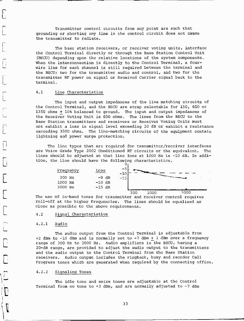
The line types that are required for transmitter/receiver interfacesare Voice Grade Type 2002 Conditioned RT circuits or the equivalent. Thelines should be adjusted so that line loss at 1000 Hz is -10 dB. In addi-tion, the line should have the following characteristics.
0
-5-10-15
Frequency Loss
300 Hz -8 dB1000 Hz -10 dB3000 Hz -15 dB
3000The use of in -band tones for transmitter and receiver control requiresroll -off at the higher frequencies. The lines should be equalized asclose as possible to the above requirements.
300 1000
4.2 Signal Characteristics
4.2.1 Audio
The audio output from the Control Terminal is adjustable from+2 dBm to -10 dBm and is normally set to -7 dBm + 1 dBm over a frequencyrange of 300 -Hz to 3000 Hz. Audio amplifiers in-the BSCU, having a20 -dB range, are provided to adjust the audio output to the transmittersand the audio output to the Control Terminal from the Base Stationreceivers. Audio output includes the ringback, busy and reorder CallProgress tones which are generated when required by the connecting office.
4.2.2 Signaling Tones
The idle tone and seize tones are adjustable at the ControlTerminal from no tone to +3 dBm, and are normally adjusted to -7 dBm
33
+ 1 dBm output to the telephone line. The Control Terminal tonedetectors are within 25 Hz when adjusted for the center frequencies forthe guard, connect and disconnect IMTS tones, at 25°C and -48 VDC inputpower. The tones will be properly decoded over a dynamic range of 12 dBwhen the nominal input to the Control Terminal is -17 dBm with -3.3 kHzdeviation carrier applied.
4.2.3 Call Progress Tones
In addition to the idle and seize tones, 350-, 440-, 480- and620- Hz tones are used to generate Call Progress signals to the MUusers. These signals are described in the following sections. (Ring -
back and busy tones are excluded; these are generated by the connectingoffice. See Section 4.2.1. Reorder is generated either by the connec-ting office or the Control Terminal depending where the blockage occurs.)The tone generators in the Control Terminal have a frequency toleranceof +0.5%, and an output amplitude tolerance of +1 dB. The total
distortion is less than 1%.
4.2.3.1 Dial Tone
The dial tone is composed of the 350Hz tone and the
440 Hz tone. The output of this signal from the Control Terminal tothe BSCU is adjustable from -3 dBm to no signal and is set at a levelof -13 dBm +1 dBm per frequency. The tone pair when transmitted is
continuous.
4.2.3.2 Reorder Tone
The reorder (overflow) tone is composed of the 480 Hz
tone and the 620 Hz tone. The output of this signal from the ControlTerminal to the BSCU, that is interrupted at a 120 IPM rate, is adjust-able from -11 dBm to no signal, and is set at a level of -21 dBm + 1
dBm per frequency. The signal is on for 300 + 50 msecs and off for
200 + 50 msecs.
4.2.3.3 Receiver Off Hook (ROH) Tone
The ROH tone is the 480 Hz tone transmitted to the BSCU
at a level of -8 dBm and interruption rate of 240 IPM. The output from
the terminal of this signal is adjustable from +2 dBm to no tone.
4.2.4 Station Call Sign Signals
Station FCC call signs are generated each 30 minute (+0, -10minutes) interval unless the channel is busy, in which case the call sign
is sent at the end of the call. Call signs are sent in InternationalMorse Code using the seize tone, at a rate of 20 to 25 words per minute.
The level of the signal is as specified for the seize tone in Section4.2.2.
4.2.5 Transmitter Control Tones
Combinations of three audio tones are used to select transmitter
power settings. An absence of any tone is a command to standby power
(no RF radiation). The 2000 Hz idle tone commands the transmitter to
34

full power. When the channel is seized and the idle marker removed, a2962 Hz tone is sent to the BSCU to keep the transmitter at full power.When the call or call attempt is completed, the channel is commanded toony one of three states: back to marked idle, to Fo power or to the
standby mode. The tone signals and their characteristics are given inthe following paragraphs.
4.2.5.1 Tone Frequencies
Tone Frequencies Transmitter Condition Remarks
2000 + 10 Hz
2962 + 10 Hz
2794 + 10 Hz
2962 + 10 Hz and2794 + 10 Hz
No Tone
Full Power
Full Power
Fo Power
Test Convert
Idle Marker ON
Channel Busy
0.5 W, unmodulated
Full Power -Manual Only
Standby Power No RF Radiation
The 2962 Hz Channel Busy tone is applied when a channel is seizedand the 2000 Hz marker tone is removed.
4.2.5.2 Tone Levels
The 2000 Hz idle tone is adjustable from +3 dBm to notone, and is normally sent to the BSCU at -7 + 1 dBm. The 2962 and2794 Hz tones are adjustable from -50 to -30 dBm, and are normally sentat a level to be -35 + 2 dBm at the BSCU.
4.2.6 Transmitter Control Signals
The transmitter control tone signals sent from the ControlTerminal to the BSCU are converted by the BSCU into either loop -currentsignals or contact closure signals that interface the transmitters.
4.2.6.1 Loop -Current Signals
The loop -current signals are applied to a line pairbetween the BSCU and each transmitter as shown in the following table:
Signal Current Range Remarks
Full Power +2.5 to +3.0 ma Marker or Busy
Fo Power -2.5 to -3.0 ma
Test Convert +10.0 to +9.0 ma
Off (Standby) 0 Open Current
35

4.2.6.2 Contact Closure Signals
A separate relay contact is provided in the BSCU foreach of the following signals: Full Power (marker or busy), Fo Power,and Test Converter mode. The signal is indicated when the contact isclosed. When all three contacts are open, the transmitter is commandedto Off (Standby). The contacts are rated at 240 ma or 10 volt-amperesresistive.
4.2.7 Status Signals
4.2.7.1 Transmitter RF-On
The BSCU contains an interface to the transmitter toprovide an RF carrier On indication to the Control Terminal. The RF-Onsignal is transferred to the BSCU from the transmitter by either loop-current or contact -closure signaling.
The BSCU converts the RF-On signal from the transmitter to a tonesignal of 2962 Hz + 10 Hz that is transmitted back to the Control Ter-minal over either the receive audio pair, or a special pair providedfor this signal. The tone is adjustable from -50 to -30 dBm and is nor-mally set to provide a -30 dBm + 2 dBm signal at the Control Terminal.
An RF-On indicator is provided for each transmitter at the BSCU.The indicators are lighted when the Power On signals are received fromthe transmitters.
4.2.7.1.1 Loop -Current Signaling
The RF-On signal is generated as a result of a returncurrent of from +4 ma to +6 ma on the audio pair from the transmitter(indicating transmitter RF relay closure).
4.2.7.1.2 Contact Closure Signaling
The BSCU detects the closure of a contact over a specialline pair from the transmitter as an indication of RF power on. TheBSCU will generate a maximum of 5 ma through the contact at a maximumline and contact resistance of 1000 ohms.
4.2.7.2 Received Carrier
The Control Terminal has provisions for monitoring allchannels (receivers) for the presence of an RF carrier. Tone or DCcurrent signals from the receivers or Receiver Voting Units are convertedby the BSCU into 3100 Hz audio tone signals that are transmitted to theControl Terminal. The signals from the receivers and voting units aretransmitted on the audio pair of the talk channel between these units andthe BSCU. For those configurations where the receivers or voting unitsare co -located or near the Control Terminal their outputs are connecteddirectly to the terminal, bypassing the BSCU.
36

4.2.7.2.1 Tone Signaling
The BSCU can detect and process a 1950 + 10 Hz audio tone from
a receiver as an indication of no carrier being received at the input
to the receiver. A level of at least -30 dBm is required at the input
to the BSCU.
NOTE: If the IMTS system operates without receiver voting, the 1950 Hztone will be heard by a land party until the called mobilesubscriber answers.
4.2.7.2.2 DC Current Signals
Receivers with carrier -operated relays (COR) providing a closedcontact across the audio pair between the receiver and the BSCU when acarrier is being received, are interfaced by feeding a 4 to 10 ma
current through the loop from the BSCU, or from the Control Terminal if
the received audio is not routed through the BSCU. The current is de-
tected through the closed loop by the BSCU or terminal, and generatesthe received carrier signal. Receivers that provide a COR to switch ina current source generator, must provide a current of 4 to 10 ma tothe input of the BSCU, or Control Terminal.
The BSCU and Control Terminal can also operate with receiversthat supply either a ground or battery (-48 VDC) on one of the lines ofthe audio pair, when a carrier is being received. Either method requires
4 to 10 ma of current. This technique provides only two states of
operation:
1) Carrier present (high current)
2) No carrier or line bad or receiver bad (low or no current.).
37

5.0 CONTROL TERMINAL PHYSICAL INTERFACE
The Control Terminal exhibits the hardware characteristics identifiedin the following paragraphs.
5.1 Packaging Configuration
5.1.1 Control Terminal Rack Assemblies
The Control Terminal is packaged in standard racks similar to theconfiguration shown in Figure 2.2-1 of the Proposal Section. Each rackis designated by serial number and type by means of permanent markingson the rack frame in a visible, but unobtrusive, location.
Standard frames for 23 -inch chassis, that can be bolted to the floorof the facility, house the various chassis. The base of each frame incontact with the floor has a surface area of 291 square inches. The overallframe widths are each 25 inches. Chassis mounted in the frames are self-contained modular units. The height dimension of each chassis is a multipleof standard, 1.75 -inch -panel increments. The chassis are configured not toexceed 7-1/2 feet in height. The rack mounted equipment does not extendmore than 12 inches from the center of the rack, with an overall dimensionof 16.5 inches, to allow proper aisle clearance for maintenance and testequipment.
Except for the blower chassis in the Interface and Control Rack,individual chassis can be added or removed from a rack without disturbingthe other units in the frame. In addition, the Control Terminal confirgura-tion is easily modified by adding or removing an entire rack without majorequipment modification.
Frames, chassis, and internal modules are labeled to allow identifi-cation during operation and maintenance without equipment disassembly.
All equipment is finished with a paint (Fed STD -595 Gray) that isuniform in color and lustre and resists scratching. Rack -mounted equipmentis protected by metal enclosures with front and rear panels.
5.1.2 Base Station Control Unit
The BSCU is a chassis having a standard 19 -inch wide panel, 12-1/4inches high and a chassis depth of 16-1/2 inches, and is capable ofcontrolling from one to six transmitters.
5.1.3 Receiver Voting Unit
A Receiver Voting Unit is contained in a chassis having a standard19 -inch wide panel, 7 inches high and 9-1/2 inches deep, and a jack fieldhaving a 19 -inch wide panel 1-3/4 inches high and 6 inches deep. The unitcan vote the outputs of from two to six receiver sites on a frequencychannel. An extender unit of the same size increases the vote capabilityto as many as 12 sites.
38

5.1.4 Teletypewriter and Stand
The teletypewriter set is 22 inches wide by 8-3/8 inches high by18-1/2 inches deep. The stand for the set is 17-3/4 inches wide by 24-1/2inches high and 6-1/2 inches deep. The rail -type feet of the stand are17-3/4 inches long.
5.2 Weights and Floor Loading
5.2.1 Control Terminal Rack Assemblies
The maximum loading exerted on the floor by the Control
Terminal racks is 2.25 pounds per square inch.
5.2.2 Teletypewriter and Stand
The TTY set weighs 44 pounds, and the stand weighs 12 pounds.
5.2.3 Base Station Control Unit
The BSCU with six transmitter control modules weighs lessthan 50 pounds.
5.2.4 Receiver Voting Unit
The Receiver Voting Unit with six receiver modules weighsless than 30 pounds.
5.2.5 Base Station Interface Rack
A standard frame for 19 -inch chassis contains BSCU's andReceiver Voting Units* The base of each frame in contact with the floorhas a surface area of 247 square inches.
5.3 Environment
5.3.1 Control Terminal Rack Assemblies
The Control Terminal racks operate within the specified toler-ances of this document over a temperature range of 50°F to 113°F (10°C to45°C)., and a relative humidity range of from 20% to 95%, non -condensing.
5.3.2 Base Station Control Unit
The BSCU operates within the specified tolerances of this docu-ment over a temperature range of 32°F to 131°F (0°C to 50°C), and a relativehumidity range of from 5% to 95%, non -condensing.
*If Receiver Voting Units are located at Base Station site.
39

5.3.3 Receiver Voting Unit
The Receiver Voting Unit operates within the specifiedtolerances of this document over a temperature range of 32°F to140°F (0°C to 60°C), and a relative humidity range of 5% to 95%noncondensing.
5.3.4 Teletypewriter
The TTY set operates within the specified tolerances ofthis document range of 41°F to 110°F (5°C to 43°C), and a relativehumidity range' of 5% to 95% noncondensing.
5.4 Power Requirements
The various components of the system utilize -48 VDC and/or 115VAC input power. The equipment meets the requirements specified inthis document over the following input power ranges:
-45 VDC, to -52 VDC
115V * 10%, 10, 60 Hz * 3 Hz
5.4.1 Control Terminal Rack Assemblies
Processor Rack: A single processor configuration requires25 Amperes at -48 VDC. In addition, the rack may be operated from abackup AC power source (automatic switchover provided in case of DCpower failure) of 8.5 Amperes at a 0.9 power factor. For the dualprocessor configuration, 50 Amperes of DC power is required with aback-up source of 17 Amperes AC.
Interface and Controls Rack: A full complement of chassisand cards requires 27 Amperes of -48 VDC power. An additional 3.84Amperes of "clean" -48 VDC is required for supervisory signals.
Magnetic Tape Rack: The dual tape unit configuration re-quires 13 Amperes -from -48 VDC power source. This rack also hasprovisions for automatic switchover to a back-up AC power source of6 Amperes at a power factor of 0.83.
Auxiliary Rack: The single magnetic tape configuration inan Auxiliary Rack also containing a full complement of equipment(casette/cartridge tape recorder, with a magnetic tape unit installed,voice announcement unit*, unibus switch, and test equipment) requires21 Amperes at -48 VDC with an AC back-up source of 9 Amperes. Thefull -complement Auxiliary Rack without the magnetic tape unit re-quires 25 Amperes at. -48 VDC with an AC back-up source of 8.5Amperes at -48 VDC with an AC back-up source of 8.5 Amperes at a 0.9power factor.
5.4.2 Base Station Control Unit
A Base Station Control Unit with six transmitter controlmodules requires 2.0 Amperes of AC power.
*Voice announcement unit operates on DC only.
40
5.4.3 Receiver Voting Unit
A Receiver Voting Unit with six receiver modules requires 1.0
Ampere of AC power.
5.4.4 Teletypewriter
The teletypewriter requires 10 Amperes at -48 VDC or 15 Amperesof AC current for starting, and 4.0 Amperes of AC power during normal opera-
tion.
5.5 Safety Features
To assure safe Control Terminal operation, the following safety
features are employed.
1 All high voltage lines in a rack are marked with a visible
WARNING sign. All high voltage terminal blocks are suitably covered orotherwise protected from accidental contact by craftsmen performing
routine maintenance.
2 Suitable latches or locks are incorporated to prevent chassisfrom being removed from the rack in one singular push or pull motion.
3 Lights are employed to give a positive indication when rackpower is "ON".
4 Operating instructions are supplied with each Control Terminaland contain any information relative to safe operation.
41

6.0 MAN -MACHINE INTERFACE
System control and monitoring functions are performed by a systemtechnical operator's interface with the Control Terminal processor. Thesystem technical operator utilizes processor peripheral equipment, namelythe teletypewriter and magnetic tape facilities, in order to exercisehis control. To further assist the technical operator, test jacks,switches, keys, indicators, fuses and alarms are located on the front ofappropriate equipment.
6.1 System/Operator Interface
The comprehensive man/machine software package provides the meansfor an operator to communicate with the system via a teletypewriter.Table 6.1-I lists the standard technical operator control commands. Allof the commands can be executed from the teletypewriter. Control via theteletypewriter allows the operator to perform the following functions:
1 Control system operation.
2 Enter date and print date and time of day.
3 Add and remove subscribers to and from the directories.
4 Print or punch the current directories on the teletypewriter, orrecord on the cassette tape.
5 Determine specific subscriber status.
6 Place specific equipment in and out of service.
7 Determine specific equipment and call status.
8 Override system control of transmitter modes.
9 Perform diagnostic testing of specific equipment.
10. Switch standby equipment into operation.
11 Provide backup capability for recording of billing data.
12 Provide entry of security and ID information.
13 Print statistics.
14 Provide for exercise of optional functions.
All comamnds as listed in Table 6.1-I are identified by two alpha-betic characters. Numeric information that may follow as parameterinput must be decimal. Requests and data that are entered are checkedby the system for format validity, then processed to execute the requestedfunction. Operator and system responses are listed below.
42
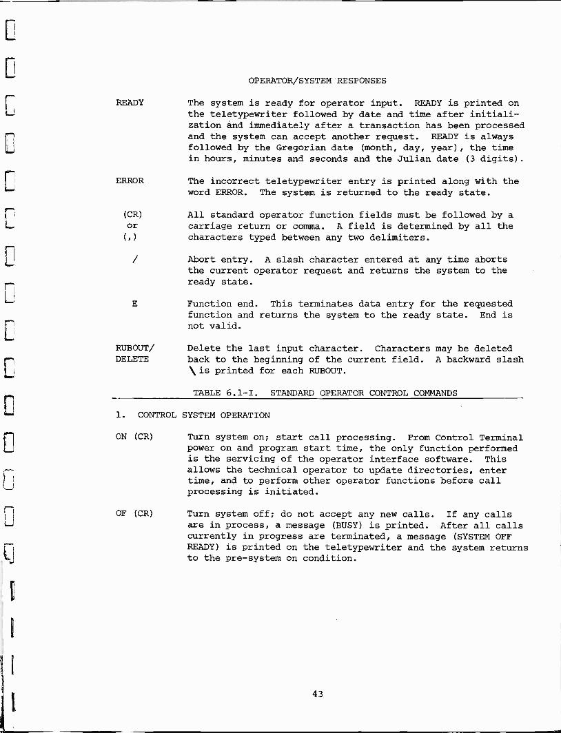
READY
OPERATOR/SYSTEM RESPONSES
The system is ready for operator input. READY is printed onthe teletypewriter followed by date and time after initiali-zation and immediately after a transaction has been processedand the system can accept another request. READY is alwaysfollowed by the Gregorian date (month, day, year), the timein hours, minutes and seconds and the Julian date (3 digits).
ERROR The incorrect teletypewriter entry is printed along with theword ERROR. The system is returned to the ready state.
E
All standard operator function fields must be followed by acarriage return or comma. A field is determined by all thecharacters typed between any two delimiters.
Abort entry. A slash character entered at any time abortsthe current operator request and returns the system to theready state.
Function end. This terminates data entry for the requestedfunction and returns the system to the ready state. End isnot valid.
RUBOUT/ Delete the last input character. Characters may be deletedDELETE back to the beginning of the current field. A backward slash
is printed for each RUBOUT.
TABLE 6.1-I. STANDARD OPERATOR CONTROL COMMANDS
1. CONTROL SYSTEM OPERATION
ON (CR)
OF (CR)
Turn system on; start call processing. From Control Terminalpower on and program start time, the only function performedis the servicing of the operator interface software. Thisallows the technical operator to update directories, entertime, and to perform other operator functions before callprocessing is initiated.
Turn system off; do not accept any new calls. If any callsare in process, a message (BUSY) is printed. After all callscurrently in progress are terminated, a message (SYSTEM OFFREADY) is printed on the teletypewriter and the system returnsto the pre -system on condition.
43

TABLE 6.1-I. STANDARD OPERATOR CONTROL COMMANDS (Cont'd)
2. ENTER DATE AND PRINT TIME OF DAY
AY (CR) Date is entered as month, day, year. Leading zeros are notM, D, YY(CR) necessary for the month and day. Year must be two digits.
Date and time are printed after entry is made. Conversionis also made to Julian date.
PT (CR) Print date and time. Date and time are printed on the tele-typewriter in the following format: Month -day -year hours
minutes seconds Julian date. Example: 11-16-73 12 25 42 320
3. ADD AND REMOVE SUBSCRIBERS TO AND FROM DIRECTORIES
AD (CR)NPA (CR)Sl:Z, S2:ZSN, E (CR)
RD (CR)NPA (CR)SN, E (CR)
AR (CR)Si, S2, S3..SN, E (CR)
Add subscriber to the home directory. Up to 10,000 mobilenumbers for each valid area code can be entered. NPAmust be a valid three -digit home area code. Sl, S2, . . SN
are four -digit subscriber mobile numbers. Leading zerosdo not have to be entered. These 4 digits are followed bya colon (:) and the zone identification, either a 1 or 2digit number between 1 and 15.* Example: 1234:4. E isthe terminating character. Entry óf a number already inthe directory will cause an ERROR printout.
Remove subscriber from home directory. NPA must be a validthree digit home area code. Si, S2, S3 . . SN are fourdigit subscriber mobile numbers. Leading zeros do not haveto be entered. E is the terminating character. Entry ofa number not in the directory will cause an ERROR printout.Service for these subscribers is deleted from the specifieddirectory.
Add numbers to the negative directory. By selective for-matting of Si, S2, S3 . . SN this command will perform thefollowing functions:
If S = 3 digit valid NPA, the entire NPA is placed in thenegative directory. If S = 7 digit number, that singlesubscriber is added. If S = 7 digit followed by a "1",this indicates that start of a block of consecutive as-cending numbers to be added. If S = 7 digit number followedby a "2", this indicates the end of a block.Example: 30510001, 30519992. These subscribers are deniedservice by the system.
RR .(CR) Remove numbers from the negative directory. S is formattedSl, S2, S3.. the same as in the AR command. Removal of blocks must cor-
SN, E (CR) respond to identical blocks currently in the directory.These subscribers are now to be allowed service.
*Option. Used only if area of registry identification/zone ID option is selected.
44

TABLE 6.1-I. STANDARD OPERATOR CONTROL COMMANDS (Cont'd)
4. PRINT OR PUNCH THE CURRENT DIRECTORIES ON THE TELETYPEWRITER ORRECORD ON THE CASSETTE TAPE
PD (CR)
NPA (CR)
(CR) ORT (CR)
CD (CR)
CL (CR)
Punch and/or print all subscriber numbers in the directorywith area code NPA. A message is printed for the operatorto allow him the option to punch a tape. Subscriber infor-mation is punched in the format as described under addingsubscribers to the directory. If a tape is produced, it maybe read back into the system. Entering an NPA code of 000designates the negative directory.
Dump directory (both Negative and Positive Directories)information to cassette recorder. The home directoriesand negative directory are written on the cassette recorder.All information is written in binary. This command can onlybe executed in the pre -system on or OFF state.
Load directory information from the cassette recorder. Homedirectories and negative directory are read from the cassette.The command can only be executed in the system states asexplained above.
5. DETERMINE SPECIFIC SUBSCRIBER STATUS
RS (CR) Negative status. Prints the negative directory for the NPANPA (CR) entered.
RS (CR)S (CR)
HS (CR)
NPA (CR)
S (CR)
Negative status. S is a seven digit number. Prints ACTIVEif S is not in the negative directory. Prints INACTIVE if Sis in negative directory.
Home status. NPA is a three digit valid home area code.S is a one to four digit number. Prints ACTIVE if S is inhome directory. Prints INACTIVE if S is not in homedirectory.
6. ADD OR REMOVE SPECIFIC EQUIPMENT IN AND OUT OF SERVICE
RT (CR) Remove trunk from system use. The trunk number TT is re -TT (CR) moved from service.
AT (CR) Add trunk for system use. The trunk number TT is addedTT (CR) back into service for system use.
RC (CR) Remove channel from system use. The channel number CC isCC (CR) removed from service.
AC (CR) Add channel for system use. The channel number CC is addedCC (CR) back into service for system use.
45

TABLE 6.1-I. STANDARD OPERATOR CONTROL COMMANDS (Cont'd)
7. DETERMINE SPECIFIC EQUIPMENT AND CALL STATUS
KC (CR)CC (CR)
KT (CR)TT (CR)
PA (CR)CC (CR)
Print status of channel. The current status of channelCC (ACTIVE, INACTIVE, BUSY, or TEST REQUIRED) is printedon the teletypewriter.
Print status of trunk. The current status of trunk TT(ACTIVE, INACTIVE, BUSY, or TEST REQUIRED) is printed onthe teletypewriter.
Print activity status for channel CC. The following infor-mation is printed: Channel number, mobile number, landline number, and channel seize time.
8. OVERRIDE SYSTEM CONTROL OF TRANSMITTER MODES
XS (CR)T (CR)
XF .(CR)
T (CR)
XM (CR)T (CR)
XV (CR)T (CR)
XR (CR)T (CR)
Place transmitter T in standby mode.
Place transmitter T in F zero mode.
Place transmitter T in marker mode.
Place transmitter T in voice mode.
Reset transmitter T to automatic mode.
9. PERFORM DIAGNOSTIC TESTING
SD (CR)
ED (CR)
DC (CR)
Start diagnostic testing. The automatic diagnostic testprocedure is started.
End diagnostic testing. The automatic diagnostic test pro-cedure is stopped.
Return system diagnostics to active service.
10. SWITCH STANDBY EQUIPMENT INTO OPERATION
ST (CR)
NT (CR)
Switch to standby central timer card. Switch all basicsystem timing functions to be performed to the standbycentral timer card.
Return to primary central timer card. Switch all basicsystem timing functions to be performed to the primarycentral timer card.
46
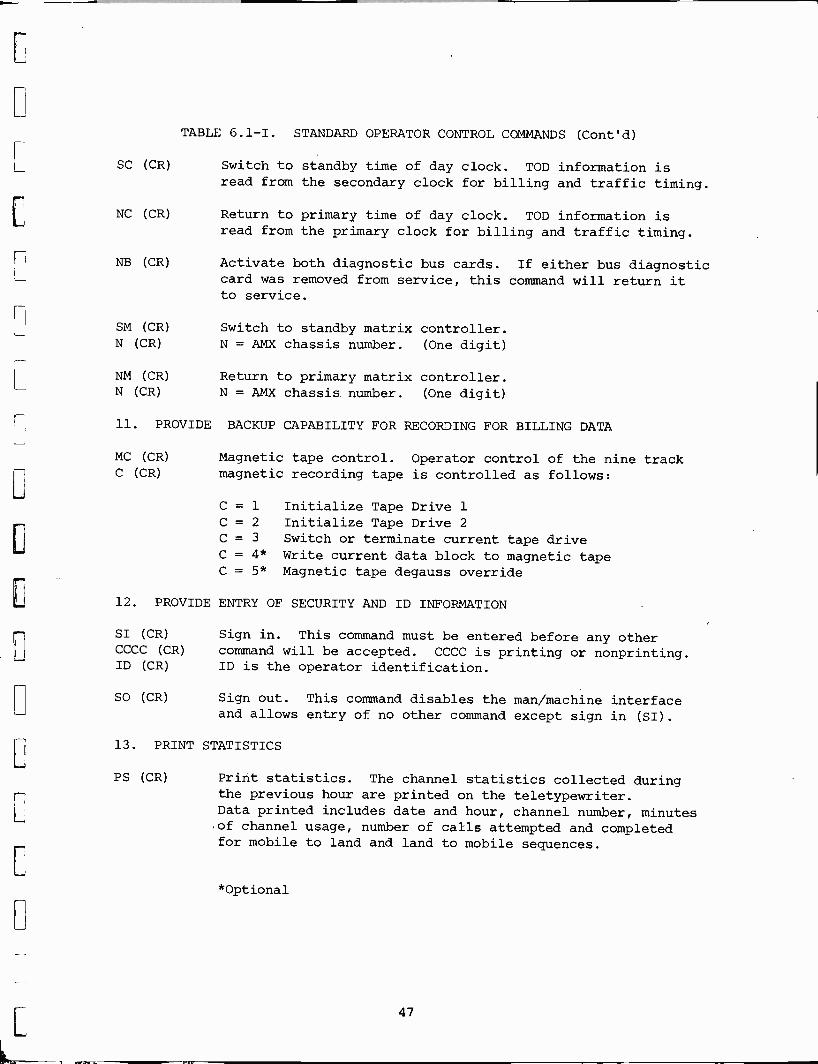
SC (CR)
NC (CR)
NB (CR)
SM (CR)N (CR)
NM (CR)N (CR)
TABLE 6.1-I. STANDARD OPERATOR CONTROL COMMANDS (Cont'd)
Switch to standby time of day clock. TOD information isread from the secondary clock for billing and traffic timing.
Return to primary time of day clock. TOD information isread from the primary clock for billing and traffic timing.
Activate both diagnostic bus cards. If either bus diagnosticcard was removed from service, this command will return itto service.
Switch to standby matrix controller.N = AMX chassis number. (One digit)
Return to primary matrix controller.N = AMX chassis number. (One digit)
11. PROVIDE BACKUP CAPABILITY FOR RECORDING FOR BILLING DATA
MC (CR)
C (CR)Magnetic tape control. Operator control of the nine trackmagnetic recording tape is controlled as follows:
C = 1 Initialize Tape Drive 1C = 2 Initialize Tape Drive 2C = 3 Switch or terminate current tape driveC = 4* Write current data block to magnetic tapeC = 5* Magnetic tape degauss override
12. PROVIDE ENTRY OF SECURITY AND ID INFORMATION
SI (CR) Sign in. This command must be entered before any otherCCCC (CR) command will be accepted. CCCC is printing or nonprinting.ID (CR) ID is the operator identification.
SO (CR) Sign out. This command disables the man/machine interfaceand allows entry of no other command except sign in (SI).
13. PRINT STATISTICS
PS (CR) Print statistics. The channel statistics collected duringthe previous hour are printed on the teletypewriter.Data printed includes date and hour, channel number, minutes,of channel usage, number of calls attempted and completedfor mobile to land and land to mobile sequences.
*Optional
47

TABLE 6.1-I. STANDARD OPERATOR. CONTROL COMMANDS (Cont'd)
14. PROVIDE FOR THE EXERCISE OF OPTIONAL FUNCTIONS
AA (CR) Add mobile test number.S, E (CR) S = number of mobile unit. (7 digits)
E = terminating characterMobiles undergoing maintenance calls are specially flaggedso automatically they will not be billed for the test calls.
RA (CR) Remove mobile test number.S, E (CR) S = number of mobile unit to be removed. (7 digits)
S = 0 All mobile test numbers are removedE = terminating character
PN (CR)
SS (CR)
SX (CR)
CC (CR)
RX (CR)CC (CR)
EA (CR)
DA (CR)
Print all mobile test numbers.All mobiles whose numbers have been entered while undergoingmaintenance test calls are listed on the teletypewriter.
Print status of all channels and trunks. Each trunkor channel's status (ACTIVE, INACTIVE, BUSY, or TEST REQUIRED)is printed on the teletypewriter.
Switch standby channel card into service. The channelnumber CC is switched into service.
Return standby channel card to standby service. The channelnumber CC is removed from service.
Enable alarms. The system major and minor alarms can bereturned to service after being disabled.
Disable alarms. The system major and minor alarms can beremoved from service for the convenience of the systemtechnical operator.
AB (CR) AB = add abbreviated dialed numberNPA (CR) NPA = mobile unit's area codeU (CR) U = mobile unit's number (4 digits)11X, DD (CR) X = 0 to 9, the abbreviated numberE (CR) DD = the digits to be dialed
E = terminating character
RB (CR)NPA (CR)U (CR)E (CR)
RB = remove abbreviated dial userNPA = mobile unit's area codeU = mobile unit's number (4 digits)E = terminating character
48

PB (CR)(CR)
PB (CR)
NPA (CR)(CR)
PB (CR)NPA (CR)U (CR)
VS (CR)L (CR)
TABLE 6.1-I. STANDARD OPERATOR CONTROL COMMANDS (Cont'd)
Print abbreviated dial users. All mobile subscribers inall the terminals's home NPA's are printed on thetypewriter.
Print abbreviated dial users. All mobile subscribers inthis NPA are printed on the teletypewriter.
Print abbreviated dialed numbers. All abbreviated dialednumbers for mobile subscriber U are printed on the tele-typewriter. NPA is the subscriber's area code.
Variable statistics.L = 1 to 24. Statistics are gathered for the number of hoursindicated, then automatically printed on the teletype-writer. L = jó. Statistics are gathered hourly. Printoutmust be manually requested using the PS (CR) command.
MC (CR) Magnetic tape identification.N (CR) N = 1 or 2, depending upon which magnetic tape unit isNNNNNN (CR) selected. NNNNNN is up to a 6 digit ID number for the tape.
BA (CR) Activate all channels busy.Cl, C2 ... Cl, C2 ... are the channel numbers. E is the terminatingE (CR) character. All specified channels are put in a busy
condition.
BR (CR)Cl, C2E (CR)
Deactivate all channels busy. Format is the same as forBA command. All specified channels are returned toactive service.
49

7.0 MAGNETIC TAPE OUTPUT
All channel usage statistics, call records, time records, plantstatistics, call billing data and tape transfer records are collected incomputer format on magnetic tape.
When computer tapes are changed, tape records are used to prefaceand end a tape. If the tape change is made manually, where the operatorcommands the CPU to switch the tapes, the ending format will appear. Ifthe CPU switches automatically due to a fault in one magnetic tape re-corder, the trailer will not appear, but the header will appear on thebackup tape recorder. These headers and trailers include:
1 Time and date
2 Tape identification
3 Record counts
4 Tape transport record
See Table 7.0-I for standard Transfer In Label tape format.
See Table 7.0 -II for standard Transfer Out Label tape format.
Hourly channel usage statistics include:
1 Time data
2 Attempted calls
3 Completed calls
4 Usage time
See Table 7.0 -III for standard Channel Usage Statistics tape format.
Call record statistics include:
1 Mobile number
2 Land number (ON MOBILE -TO -LAND CALLS)
3 Time data
4 Radio channel used
5 Call class indicator
50

See Table 7.0 -IV for standard Call Record tape format.
See Table 7.0-V for standard Call Class Indicators.
Time change and control records are used when there is a change incomputer processor clock. The statistics include:
1 Old date and time
2 New date and time
3 Current date and time
4 Processor used
See Table 7.0 -VI for standard Time Change Record tape format.
See Table 7.0 -VII for standard Time Control tape format.
Plant Statistics or TTY Communications are a record of all commandsentered through the TTY. The record includes:
1 Current time
2 Alpha/numeric inputs
See Table 7.0 -VIII for standard Plant Statistics or TTY Communicationstape format.
51

TABLE 7.0-I. TRANSFER IN (HEADER) LABEL FORMAT
'
Field NamePosition No. of
Contents and/or RemarksFrom To Pos.
Start of Entry 1 2 2 Constant - Hex 'CC' -1100 1100
Single Entry ID 3 3 1 Constant - Hex '1' - 0001
Format Modifier 4 5 2
Filler 6 6 1 Constant - Hex 'B' - 1011
Start Month 7 8 2 Month Tens and Units Digits
Start Day 9 10 2 Day Tens and Units Digits
Office Recording Type 11 12 2 Tens and Units Digits
Tape Identification No. 13 18 6 6 Numerics
Start Hour 19 20 2 Hour Tens and Units Digits
Start Minute 21 22 2 Minute Tens and Units Digits
In Record Count 23 30 8 8 Numerics
In Block Count 31 35 5 5 Numerics
Tape Transport Number 36 36 1 Numeric 1 or 2
CPU Program Issue 37 40 4 4 Numerics
52
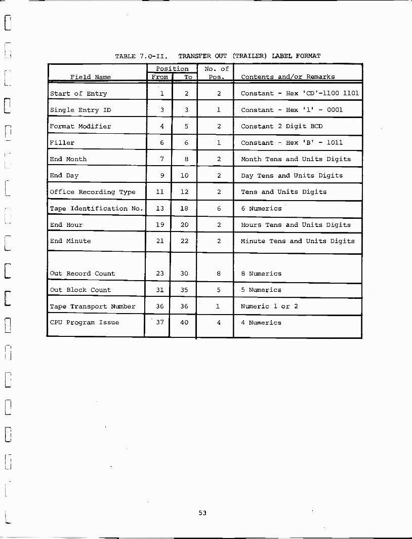
TABLE 7.0 -II. TRANSFER OUT (TRAILER) LABEL FORMAT
Field NamePosition No. of
Contents and/or RemarksFrom To Pos.1
Start of Entry 1 2 2 Constant - Hex 'CD' -1100 1101
Single Entry ID 3 3 1 Constant - Hex '1' - 0001
Format Modifier 4 5 2 Constant 2 Digit BCD
Filler 6 6 1 Constant - Hex 'B' - 1011
End Month 7 8 2 Month Tens and Units Digits
End Day 9 10 2 Day Tens and Units Digits
Office Recording Type 11 12 2 Tens and Units Digits
Tape Identification No.. 13 18 6 6 Numerics
End Hour 19 20 2 Hours Tens and Units Digits
End Minute 21 22 2 Minute Tens and Units Digits
Out Record Count 23 30 8 8 Numerics
Out Block Count 31 35 5 5 Numerics
Tape Transport Number 36 36 1 Numeric 1 or 2
CPU Program Issue 37 40 4 4 Numerics
53

TABLE 7.0 -III. CHANNEL USAGE STATISTICS FORMAT
Field NamePosition No. of
Pos. Contents and/or RemarksFrom To
Start of Entry 1 2 2 Constant - Hex 'CA' -1100 1010
Current Month 3 4 2 Month Tens and Units Digits
Current Day 5 6 2 Day Tens and Units Digits
Current Hour 7 8 2 Hour Tens and Units Digits -See Note 1
Usage - Minutes 9 12 4 Minutes Tens and Units Digits
Call Attempts (L -M) 13 16 4 Four digits (current houronly)
Calls Completed (L -M) 17 20 4 Four digits (current houronly)
Call Attempts (M -L) 21 24 4 Four digits (current houronly)
Calls Completed (M -L) 25 28 4 Four digits (current houronly)
Operator Handled Calls
See Note 2
29 32 4 Four digits per channel group
(current hour only)
Circuit Attempts, Allchannels busy
Note 2
33 36 4 Four digits per channelgroup (current hour only)
Radio Channel Trunk No. 37 38 2 Two Digit BCD
Filler 39 56 18 Constant HEX 'B's
NOTE 1: If the usage involved is from 0800 through 0859, the currenthour to be shown is 08.
2: These items are calculated on a per channel group (area) basis.
54

TABLE 7.0 -IV. CALL RECORD FORMAT
Position No. ofPos. Contents and/or RemarksField Name From To
Start of Entry 1 1 1 Constant - Hex 'C' - 1100
Mobile Number 2 8 7 NPA and Line Number I
Land Number 9 18 10 NPA, NNX, Line Number
Month-Land/RadioAnswered
19 20 2 Month Tens and Units Digits
Day-Land/Radio Answered 21 22 2 Day Tens and Units Digits
Radio Channel SeizureTime
23 28 6 Hour, Minutes and Seconds
Radio ChannelDisconnect Time
29 34 6 Hour, Minutes and Seconds
Land or Radio PartyAnswer Time
35 40 6 Hour, Minutes and Seconds
Land Party DisconnectTime
41 46 6 Hour, Minutes and Seconds
Call Class Indicator 47 48 2 See Table 7.0-V
Radio Channel TrunkNumber
49 50 2 Two Digit BCD
CO, Mobile ServiceOperator or DDDTrunk Number
51 52 2 Two Digit BCD
Filler 53 56 4 Hex 'BBBB'
55

TABLE 7.0-V. CALL CLASS INDICATORS
01 Home mobile number is in the positive file.Roam mobile number is not in the negativefile. Called Party Answer Time is recorded.
Billable Message
02 . Home mobile number is not in the positive orthe negative files.
Disconnect or wrongnumber announcement
03 Home mobile number is not in the positivefile and is in the negative file. Foreignmobile number is in the negative file.
7
Cannot be served .
announcement(()`,
04No DDD or Mobile Service Operator Trunkavailable.
Reorder Tone
05 No Radio Party Disconnect Signal. Permanent SignalBillable Message
06 Call attempted by mobile number same as onebusy on another channel.
Cannot be servedannouncement
07 Mobile number does not acknowledge. Cannot be reachedannouncementCannot be reachedannouncement
08 Mobile number acknowledges but does notanswer.
09 Mobile number busy. Busy Tone
10 All channels busy. Broadcast queue full. Reorder Tone
11 Mobile carrier lost for more than 15 secondsor any abnormal failures.
Millable message
12 Operator handled by Mobile Service Operator. Route to Mobile ServiceOperator
13 Central Office start dial not received in15 seconds.
Reorder
14 Digits dialed by mobile unit timed out Reorder Tone
15 Digits from the CO or Mobile Service Operatortrunk timed out or were not in the properform.
Reorder Tone
16 Invalid or incomplete ANI or invalid dialeddigits received from the mobile unit.
Reorder Tone
17 Called party does not answer (busy, completeto announcement, does not answer).
Disconnect when mobileunit goes on hook.
Audio from mobile lost for 2.25 min.1
I18 Billable message
56
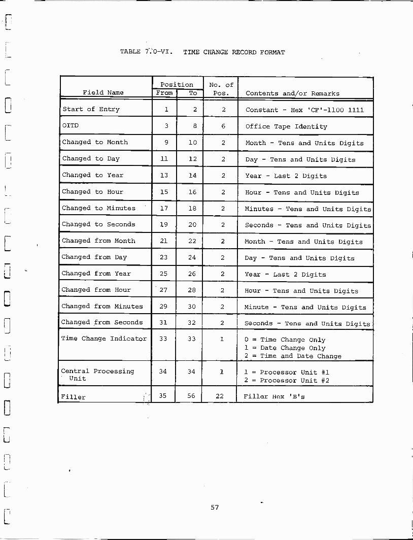
TABLE 7.0 -VI. TIME CHANGE RECORD FORMAT
Field NamePosition No. of
Pos. Contents and/or RemarksFrom To
Start of Entry 1 2 2 Constant - Hex 'CF' -1100 1111
OITD 3 8 6 Office Tape Identity
Changed to Month 9 10 2 Month - Tens and Units Digits
Changed to Day 11 12 2 Day - Tens and Units Digits
Changed to Year 13 14 2 Year - Last 2 Digits
Changed to Hour 15 16 2 Hour - Tens and Units Digits
Changed to Minutes 17 18 2 Minutes - Tens and Units Digits
Changed to Seconds 19 20 2 Seconds - Tens and Units Digits
Changed from Month 21 22 2 Month - Tens and Units Digits
Changed from Day 23 24 2 Day - Tens and Units Digits
Changed from Year 25 26 2 Year - Last 2 Digits
Changed from Hour 27 28 2 Hour - Tens and Units Digits
Changed from Minutes 29 30 2 Minute - Tens and Units Digits
Changed from Seconds 31 32 2 Seconds - Tens and Units Digits
Time Change Indicator 33 33 1 0 = Time Change Only1 = Date Change Only2 = Time and Date Change
Central ProcessingUnit
34 34 1 1 = Processor Unit #12 = Processor Unit #2
Filler 35 56 22 Filler Hex 'B's
57

TABLE 7.0 -VII. TIME CONTROL FORMAT
Field NamePosition No. of
Contents and/or RemarksFrom To Pos.
Start of Entry 1 2 2 Constant - Hex 'DA' -1101 1010
OTID 3 8 6 Office Tape Identity
Current Month 9 10 2 Month Tens and Units Digits
Current Day 11 12 2 Day Tens and Units Digits
Current Hour 13 14 2 Hour Tens and Units Digits
Current Minutes 15 16 2 Minute Tens and Units Digits
Current Seconds 17 18 2 Second Tens and Units Digits
Central ProcessingUnit
19 19 1 1 = Processor 12 = Processor 2
Current Record Count 20 27 8 8 Digit Numeric
Current Block Count 28 32 5 5 Digit Numeric
Filler 33 56 24 Filler - Hex "B"s
58

TABLE 7.0 -VIII. PLANT STATISTICS OR TTY COMMUNICATIONS FORMAT_
Field NamePosition No. of
Pos. Contents and/or RemarksFrom To
Start of Entry 1 2 2 Constant Hex 'DF' 1101 1111
Current Month 3 4 2 Month Tens and Units Digits
Current Day 5 6 2 Day Tens and Units Digits
Current Hour 7 8 2 Hour Tens and Units Digits
Current Minute 9 10 2 Minutes Tens and Units Digits
Continuation Character 11 12 2 00 = Not last record of a com-mand
01 = Last record of a command
Message Text 13 NN NN Alpha or numeric characters
Last Position 56
59

8.0 MAINTENANCE INTERFACE
Diagnostic tests are performed automatically by the processor ofthe Control Terminal. The tests are run periodically at time intervalsdepending upon the criticality of the circuits under test. Table 8.0-Iprovides a typical list of the tests showing the device tested, thealarm level and the test intervals.
In addition to lamps indicating faults, and a printout of the occur-rence on the TTY (by fault class number), three sets of relay transfercontacts having a current -carrying capability of 5 amperes at 115 VAC areprovided for each major and minor alarm to operate remote indicators inthe Central Office.
60
9.0 VOICE ANNOUNCEMENT RECORDER UNIT AUDIO INPUT INTERFACE
Recording of messages is accomplished either through the use of astandard telephone handset or a cassette playback unit. The latter maybe useful when the ambient noise level at the Voice Announcement RecorderUnit is too hob to permit a good recording with a handset.
The sensitivity level for the input to the record amplifier from a900 -ohm telephone handset is -26 dBm. The average volume when speakinginto a telephone handset provides the proper recording level. The properlevel is preset by adjusting a gain control for a VU meter reading of about0 VU. Output signal leads from the handset are at the tip and ring con-tacts of the phone plug.
The output from the earphone jack of a battery -operated cassetteplayback unit can provide for a full -level recording using an adaptercable matching a cassette mini -jack on one end and a standard 2 -conductorphone jack (Switchcraft part number 40DK05) at the other end. The recordlevel is preset by adjusting the gain level as described for the telephonehandset above.
Additional specifications for the Voice Announcement Recorder Unitare as follows: Frequency response: +3 dB, 300 to 3200 Hz; messagelength: 12 seconds; capacity: 3 message channels; SNR: 40 dB; outputimpedance: 8 ohms; output power: 0.5 W usable power capable of driving15.4600 -ohm or 225,900 -ohm trunk lines with appropriate transient protectionresistors in each line; primary power requirement: -44 to -56 VDC, 55 Wmaximum; temperature: 0°F to 140°F (-17.8°C to 60°C); humidity: 10 per-cent to 95 percent relative humidity (noncondensing); size: 12-1/4 x 19x 9 inches (311 x 483 x 229 mm) .
61

TABLE 8.0-I.
PROCESSOR CONTROLLED DIAGNOSTIC SUMMARY
DIAGNOSTIC MESSAGE PRINTOUT FORMAT
FXXX
Failure
Class
06-21-74
083845
172
MD
YH M S
Date
MESSAGE
DESCRIPTION
CARD OR CHASSIS
F000 F
010,
to F
070
Audio Matrix Module failure
AMM
F001 F
011,
to F
071
Audio Matrix controller
failure
ASX
F063
Even Bus Diagnostic failure
ADC
F065
Even Central Timer failure
ACS/ACT
N065
Even Central Timer
ACT/ACS
F067
Even Real Time Clock failure
ACK
F071
System Diagnostic failure
ASD
F073
Odd Bus Diagnostic failure
ADC
F075
Odd Central Timer failure
ACS/ACT
N075
Odd Central Timer
ACT/ACS
F077
Odd Real Time Clock failure
ACK
Time
Date
MAJOR ALARM
HOW OFTEN
OR
TEST
MINOR ALARM
CONDUCTED
Minor
Once per hour
Minor
Once per hour
Minor
Once per hour
Minor
Once per second
Minor
Real time
Minor
Once every 30 seconds
Minor
Once per hour
Minor
Once per hour
Minor
Once per second
Minor
Real time
Minor
Real time
F'100 to F 277
Trunk Interface failure
ATI, ATO
Minor
Once per day
F 300 to F 377
Radio Channel Interface failure
AIC, AIK
Minor
Once per hour
B 300 to B 377
Bandit Call Attempt on Channel
Minor
Real time
N 300 to N 377
No Station ID on Channel in
Minor
Once each 20 minutes
last 20 minutes
D 300 to D 377
Foreign Carrier detected
Minor
Real time
R 300 to R 377
Foreign Carrier removed
Minor
Real time
F 401
CP1 Processor failure
Minor (if both) Once per hour
F 402
CP2 Processor failure
Minor (Major)
Once per hour
F 405
System Diagnostic failure
ASD
Minor
Real time
F 410 to F 417
Core Memory failure On -Line
Minor
Once per hour
Processor
F 420 to F 427
Core Memory failure Off -Line Proc.
Minor
Once per hour
F 450
Auxiliary Rack Power Supply failure ADU
Minor
Once per second
F 451
CPU1 Rack Power Supply failure
ADU
Minor
Once per second
F 452
CPU2 Rack Power Supply failure
ADU
Minor
Once per second
F 453
Control and Interface Power Supply APS
Minor
Once per second
failure
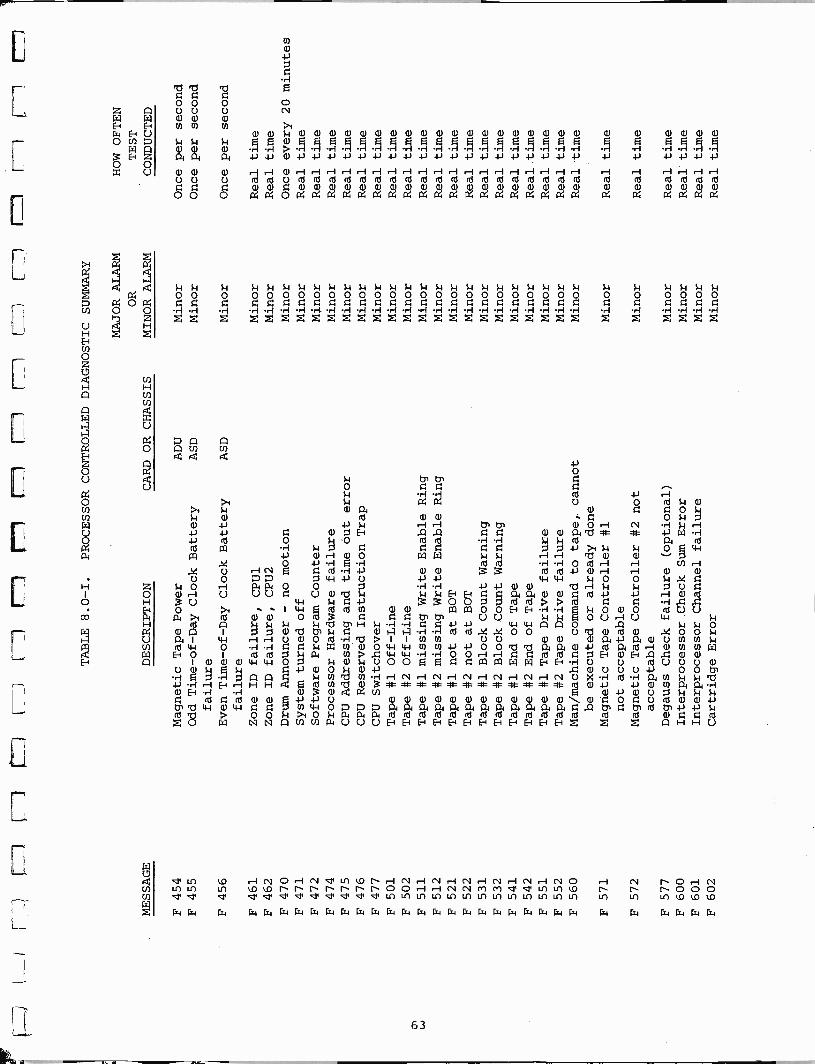
w
TABLE 8.0-I.
PROCESSOR CONTROLLED DIAGNOSTIC SUMMARY
MAJOR ALARM
HOW OFTEN
OR
TEST
MESSAGE
DESCRIPTION
CARD OR CHASSIS
MINOR ALARM
CONDUCTED
F 454
Magnetic Tape Power
ADU
Minor
Once per second
F 455
Odd Time -of -Day Clock Battery
ASD
failure
Minor
Once per second
F 456
Even Time -of -Day Clock Battery
ASD
failure
Minor
Once per second
F 461
Zone ID failure, CPU1
Minor
Real time
F 462
Zone ID failure, CPU2
Minor
Real time
F 470
Drum Announcer - no motion
Minor
Once every 20 minutes
F 471
System turned off
Minor
Real time
F 472
Software Program Counter
Minor
Real time
F 474
Processor Hardware failure
Minor
Real time
F 475
CPU Addressing and time out error
Minor
Real time
F 476
CPU Reserved Instruction Trap
Minor
Real time
F 477
CPU Switchover
Minor
Real time
F 501
Tape #1 Off -Line
Minor
Real time
F 502
Tape #2 Off -Line
Minor
Real time
F 511
Tape #1 missing Write Enable Ring
Minor
Real time
F 512
Tape #2 missing Write Enable Ring
Minor
Real time
F 521
Tape #1 not at BOT
Minor
Real time
F 522
Tape #2 not at BOT
Minor
Real time
F 531
Tape #1 Block Count Warning
Minor
Real time
F 532
Tape #2 Block Count Warning
Minor
Real time
F 541
Tape #1 End of Tape
Minor
Real time
F 542
Tape #2 End of Tape
Minor
Real time
F 551
Tape #1 Tape Drive failure
Minor
Real time
F 552
Tape #2 Tape Drive failure
Minor
Real time
F 560
Man/machine command to tape,. cannot
be executed or already done
Minor
Real time
F 571
Magnetic Tape Controller #1
not acceptable
Minor
Real time
F 572
Magnetic Tape Controller #2 not
acceptable
Minor
Real time
F 577
Degauss Check failure (optional)
Minor
Real time
F 600
Interprocessor Check Sum Error
Minor
Real time
F 601
Interprocessor Channel failure
Minor
Real time
F 602
Cartridge Error
Minor
Real time

TABLE 8.0-I.
PROCESSOR CONTROLLED DIAGNOSTIC SUMMARY
MAJOR ALRAM
HOW OFTEN
OR
TEST
MESSAGE
DESCRIPTION
CARD OR CHASSIS
MINOR ALARM
CONDUCTED
F.603
Interprocessor Channel Timer
Minor
Real time
expired
F 604
Channel Transfer reinitiated
Minor.
Real time
S XXX
Card Address
Minor
Once per how
1.-7
1L
:13
tU
E9
EE
3 e
si--
i -

-1
L__i
[L-

HARRIS Mu COMMUNICATIONS ANDINFORMAIIION NANDLINO
HARRIS CORPORATION RF Communications Division1680 University Avenue, Rochester, New York 14610