Embed Size (px)
Citation preview
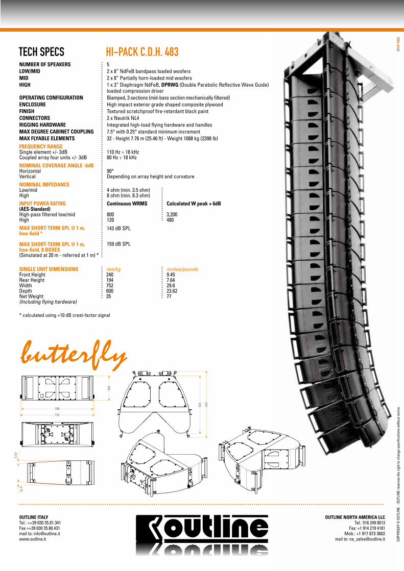
HI-PACK C.D.H. 483
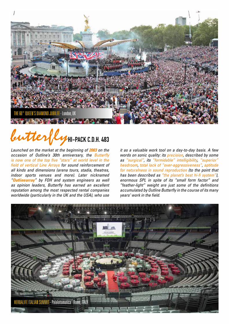
Launched on the market at the beginning of 2003 on the occasion of Outline’s 30th anniversary, the Butterfly is now one of the top five “stars” at world level in the field of vertical Line Arrays for sound reinforcement of all kinds and dimensions (arena tours, stadia, theatres, indoor sports venues and more). Later nicknamed “Outlinearray” by FOH and system engineers as well as opinion leaders, Butterfly has earned an excellent reputation among the most respected rental companies worldwide (particularly in the UK and the USA), who use
it as a valuable work tool on a day-to-day basis. A few words on sonic quality: its precision, described by some as “surgical”, its “formidable” intelligibility, “superior” headroom, total lack of “over-aggressiveness”, aptitude for naturalness in sound reproduction (to the point that has been described as “the planet’s best hi-fi system”), enormous SPL in spite of its “small form factor” and “feather-light” weight are just some of the definitions accumulated by Outline Butterfly in the course of its many years’ work in the field.
THE 60° QUEEN’S DIAMOND JUBILEE - London, UK
HI-PACK C.D.H. 483
HERBALIFE ITALIAN SUMMIT - Palalottomatica - Rome, ITALY
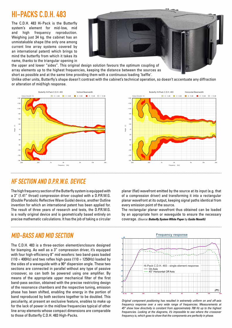
HI-PACKS C.D.H. 483
HF SECTION AND D.P.R.W.G. DEVICE
MID-BASS AND MID SECTION
Angle
[°]
Frequency [Hz]
< -12 dB-9 : -12 dB-6 : -9 dB-3 : -6 dBOctave Smooth: 1/3 +3 : -3 dB
200 500 1k 2k 5k 10k 20k
+180
+150
+120
+90
+60
+30
+0
-30
-60
-90
-120
-150
-180
Vertical BeamwidthButterfly Hi-Pack C.D.H. 483
Angle
[°]
Frequency [Hz]
< -12 dB-9 : -12 dB-6 : -9 dB-3 : -6 dBOctave Smooth: 1/3 +3 : -3 dB
200 500 1k 2k 5k 10k 20k
+180
+150
+120
+90
+60
+30
+0
-30
-60
-90
-120
-150
-180
Horizontal BeamwidthButterfly Hi-Pack C.D.H. 483
60 Hz 100 200 500 1K 2K 5K 10K 20K-40
-35
-30
-25
-20
-15
-10
-5
0
5
10
Frequency responsedB
On Axis45° Horizontal Off Axis
Hi-Pack C.D.H. 483 - single element response
The high frequency section of the Butterfly system is equipped with a 3” (1.41” throat) compression driver coupled with a D.P.R.W.G. (Double Parabolic Reflective Wave Guide) device, another Outline invention for which an international patent has been applied for. The result of three years of research and tests, the D.P.R.W.G. is a really original device and is geometrically based entirely on precise mathematic calculations. It has the job of taking a circular
planar (flat) wavefront emitted by the source at its input (e.g. that of a compression driver) and transforming it into a rectangular planar wavefront at its output, keeping signal paths identical from every emission point of the source.The rectangular planar wavefront thus obtained can be loaded by an appropriate horn or waveguide to ensure the necessary coverage. (Source: Butterfly System White Paper by Guido Noselli)
The C.D.H. 483 Hi-Pack is the Butterfly system’s element for mid-low, mid and high frequency reproduction. Weighing just 34 kg. the cabinet has an unmistakable shape (the only one among current line array systems covered by an international patent) which brings to mind the butterfly from which it takes its name, thanks to the triangular opening in the upper and lower “sides”. This original design solution favours the optimum coupling of array elements up to the highest frequencies, keeping the distance between the sources as short as possible and at the same time providing them with a continuous loading ‘baffle’.Unlike other units, Butterfly’s shape doesn’t contrast with the cabinet’s technical operation, so doesn’t accentuate any diffraction or alteration of mid/high response.
The C.D.H. 483 is a three-section element/enclosure designed for biamping. As well as a 3” compression driver, it’s equipped with four high-efficiency 8” mid woofers: two band-pass loaded (110 ÷ 400Hz) and two reflex high-pass (110 ÷ 1250Hz) loaded by the sides of a waveguide with a 90° dispersion angle. These two sections are connected in parallel without any type of passive crossover, so can both be powered using one amplifier. By means of the appropriate upper mechanical filter of the first band-pass section, obtained with the precise restricting design of the resonance chambers and the respective tuning, emission phase has been shifted, enabling the energy in the portion of band reproduced by both sections together to be doubled. This peculiarity, at present an exclusive feature, enables to make up for the lack of power in the mid/low frequencies typical of other line array elements whose compact dimensions are comparable to those of Butterfly C.D.H. 483 High-Packs.
Original component positioning has resulted in extremely uniform on and off-axis frequency response over a very wide range of frequencies. Measurements at 45° show how directivity is constant from approximately 700 Hz up to the highest frequencies. Looking at the diagrams, it’s impossible to see where the crossover frequency is, which goes to show that the components are perfectly in phase.
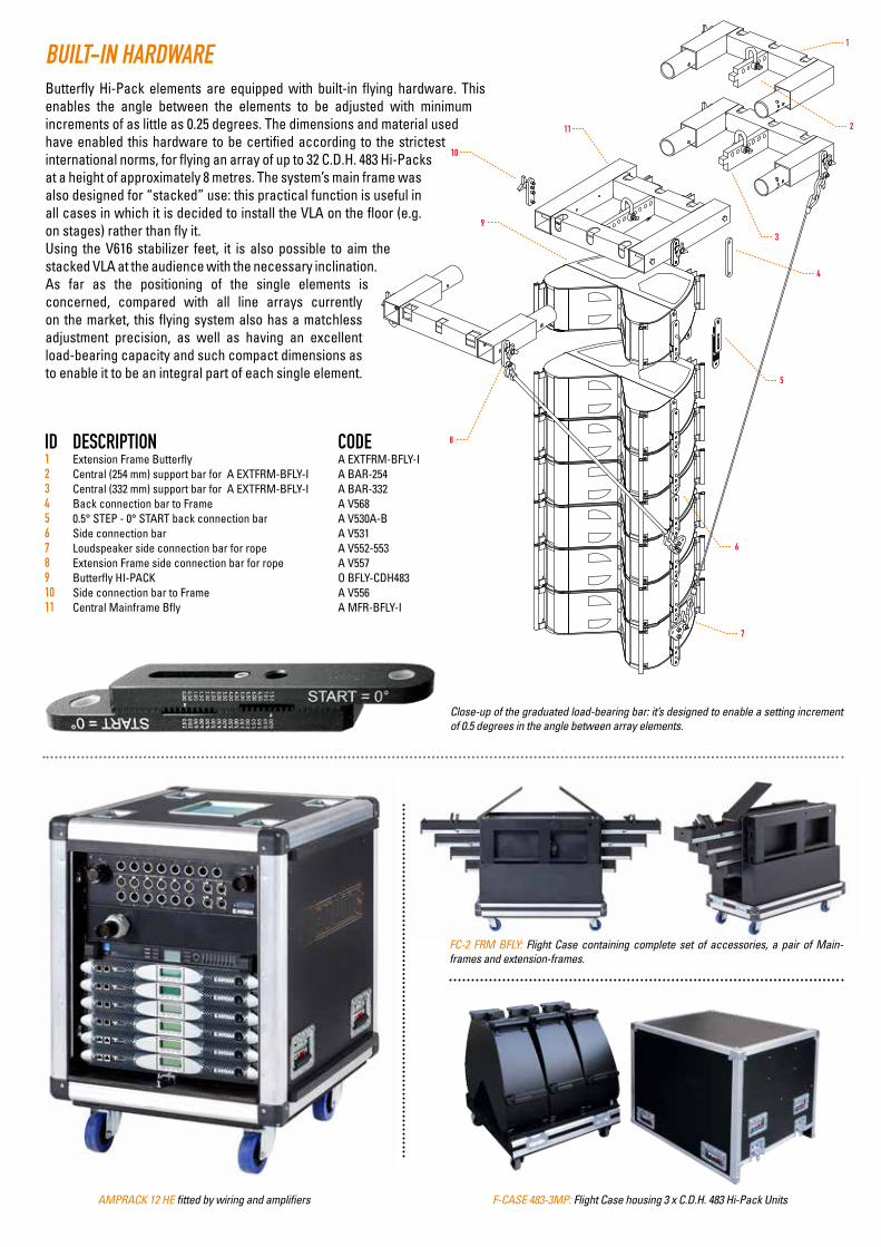
BUILT-IN HARDWARE
ID DESCRIPTION CODE1 Extension Frame Butterfly A EXTFRM-BFLY-I2 Central (254 mm) support bar for A EXTFRM-BFLY-I A BAR-2543 Central (332 mm) support bar for A EXTFRM-BFLY-I A BAR-3324 Back connection bar to Frame A V5685 0.5° STEP - 0° START back connection bar A V530A-B6 Side connection bar A V5317 Loudspeaker side connection bar for rope A V552-5538 Extension Frame side connection bar for rope A V5579 Butterfly HI-PACK O BFLY-CDH48310 Side connection bar to Frame A V55611 Central Mainframe Bfly A MFR-BFLY-I
11
10
9
8
7
6
5
4
3
2
1
Butterfly Hi-Pack elements are equipped with built-in flying hardware. This enables the angle between the elements to be adjusted with minimum increments of as little as 0.25 degrees. The dimensions and material used have enabled this hardware to be certified according to the strictest international norms, for flying an array of up to 32 C.D.H. 483 Hi-Packs at a height of approximately 8 metres. The system’s main frame was also designed for “stacked” use: this practical function is useful in all cases in which it is decided to install the VLA on the floor (e.g. on stages) rather than fly it.Using the V616 stabilizer feet, it is also possible to aim the stacked VLA at the audience with the necessary inclination.As far as the positioning of the single elements is concerned, compared with all line arrays currently on the market, this flying system also has a matchless adjustment precision, as well as having an excellent load-bearing capacity and such compact dimensions as to enable it to be an integral part of each single element.
Close-up of the graduated load-bearing bar: it’s designed to enable a setting increment of 0.5 degrees in the angle between array elements.
F-CASE 483-3MP: Flight Case housing 3 x C.D.H. 483 Hi-Pack UnitsAMPRACK 12 HE fitted by wiring and amplifiers
FC-2 FRM BFLY: Flight Case containing complete set of accessories, a pair of Main-frames and extension-frames.
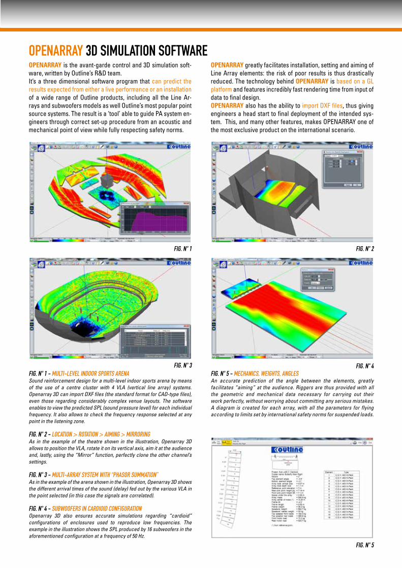
OPENARRAY 3D SIMULATION SOFTWAREOPENARRAY is the avant-garde control and 3D simulation soft-ware, written by Outline’s R&D team. It’s a three dimensional software program that can predict the results expected from either a live performance or an installation of a wide range of Outline products, including all the Line Ar-rays and subwoofers models as well Outline’s most popular point source systems. The result is a ‘tool’ able to guide PA system en-gineers through correct set-up procedure from an acoustic and mechanical point of view while fully respecting safety norms.
OPENARRAY greatly facilitates installation, setting and aiming of Line Array elements: the risk of poor results is thus drastically reduced. The technology behind OPENARRAY is based on a GL platform and features incredibly fast rendering time from input of data to final design. OPENARRAY also has the ability to import DXF files, thus giving engineers a head start to final deployment of the intended sys-tem. This, and many other features, makes OPENARRAY one of the most exclusive product on the international scenario.
FIG. N° 1 - MULTI-LEVEL INDOOR SPORTS ARENASound reinforcement design for a multi-level indoor sports arena by means of the use of a centre cluster with 4 VLA (vertical line array) systems. Openarray 3D can import DXF files (the standard format for CAD-type files), even those regarding considerably complex venue layouts. The software enables to view the predicted SPL (sound pressure level) for each individual frequency. It also allows to check the frequency response selected at any point in the listening zone.
FIG. N° 2 - LOCATION > ROTATION > AIMING > MIRRORINGAs in the example of the theatre shown in the illustration, Openarray 3D allows to position the VLA, rotate it on its vertical axis, aim it at the audience and, lastly, using the “Mirror” function, perfectly clone the other channel’s settings.
FIG. N° 3 - MULTI-ARRAY SYSTEM WITH “PHASOR SUMMATION”As in the example of the arena shown in the illustration, Openarray 3D shows the different arrival times of the sound (delay) fed out by the various VLA in the point selected (in this case the signals are correlated).
FIG. N° 4 - SUBWOOFERS IN CARDIOID CONFIGURATION Openarray 3D also ensures accurate simulations regarding “cardioid” configurations of enclosures used to reproduce low frequencies. The example in the illustration shows the SPL produced by 16 subwoofers in the aforementioned configuration at a frequency of 50 Hz.
FIG. N° 5 - MECHANICS, WEIGHTS, ANGLESAn accurate prediction of the angle between the elements, greatly facilitates “aiming” at the audience. Riggers are thus provided with all the geometric and mechanical data necessary for carrying out their work perfectly, without worrying about committing any serious mistakes.A diagram is created for each array, with all the parameters for flying according to limits set by international safety norms for suspended loads.
FIG. N° 1 FIG. N° 2
FIG. N° 4
FIG. N° 5
FIG. N° 3
BFLY
EN
G
52 x 8” NdFeB bandpass loaded woofers2 x 8” Partially horn-loaded mid woofers1 x 3” Diaphragm NdFeB, DPRWG (Double Parabolic Reflective Wave Guide) loaded compression driverBiamped, 3 sections (mid-bass section mechanically filtered)High impact exterior grade shaped composite plywoodTextured scratchproof fire-retardant black paint2 x Neutrik NL4Integrated high-load flying hardware and handles7.5° with 0.25° standard minimum increment32 - Height 7.76 m (25.46 ft) - Weight 1088 kg (2398 lb)
110 Hz ÷ 18 kHz80 Hz ÷ 18 kHz
90°Depending on array height and curvature
4 ohm (min. 3.5 ohm)8 ohm (min. 8.3 ohm)Continuous WRMS Calculated W peak + 6dB
800 3,200 120 480
143 dB SPL
159 dB SPL
NUMBER OF SPEAKERSLOW/MIDMIDHIGH
OPERATING CONFIGURATIONENCLOSURE FINISHCONNECTORSRIGGING HARDWAREMAX DEGREE CABINET COUPLING MAX FLYABLE ELEMENTSFREQUENCY RANGESingle element +/- 3dBCoupled array four units +/- 3dBNOMINAL COVERAGE ANGLE -6dBHorizontalVerticalNOMINAL IMPEDANCELow/midHighINPUT POWER RATING(AES-Standard)High-pass filtered low/mid HighMAX SHORT-TERM SPL @ 1 m,free-field *
MAX SHORT-TERM SPL @ 1 m,free-field, 8 BOXES(Simulated at 20 m - referred at 1 m) *
HI-PACK C.D.H. 483
SINGLE UNIT DIMENSIONS mm/kg inches/poundsFront Height 240 9.45Rear Height 194 7.64Width 752 29.6Depth 600 23.62Net Weight 35 77(Including flying hardware)
70 0
72 5
652
240
3,75
°
3 ,75 °
563
OUTLINE ITALYTel.: ++39 030 35.81.341Fax ++39 030 35.80.431mail to: [email protected]
OUTLINE NORTH AMERICA LLCTel.: 516 249 0013
Fax: +1 914 219 4181Mob.: +1 917 873 3602
mail to: [email protected] COPY
RIGH
T ©
OUT
LIN
E -
OUTL
INE
rese
rves
the
right
to c
hang
e sp
ecifi
catio
ns w
ithou
t not
ice.
TECH SPECS
* calculated using +10 dB crest-factor signal


![G.12.3 Industrial Production PRODUCT^! (19^7-^9 average * 100) Seas onally adjust:ed Una!justel 1957 . V556 1 j -1951 7 - ' . | pJuly I June] May July IPJuly| • June 1J'-a y 1 .LLRABLE](https://img.pdfslide.us/doc/110x75/5b3a62c77f8b9a26728b5c16/g123-industrial-production-product-197-9-average-100-seas-onally-adjusted.jpg)