Embed Size (px)
Citation preview
For more information log on www.brijrbedu.org
Brij Bhooshan Asst. Professor B.S.A College of Engg. & Technology, Mathura (India)
Copyright by Brij Bhooshan @ 2013 Page 1
HHeeaatt aanndd MMaassss TTrraannssffeerr
CChhaapptteerr -- 99 RRaaddiiaattiioonn HHeeaatt TTrraannssffeerr
PPrreeppaarreedd BByy
BBrriijj BBhhoooosshhaann
AAsssstt.. PPrrooffeessssoorr
BB.. SS.. AA.. CCoolllleeggee ooff EEnngggg.. AAnndd TTeecchhnnoollooggyy
MMaatthhuurraa,, UUttttaarr PPrraaddeesshh,, ((IInnddiiaa))
SSuuppppoorrtteedd BByy::
PPuurrvvii BBhhoooosshhaann
In This Chapter We Cover the Following Topics
Art. Content Page
9.1 Prevost’s Theory 3
9.2 Radiation Property 3
9.3 Stefan’s Law 5
9.4 Emissive Power 5
9.5 Emissivity 6
9.6 Kirchhoff's Law 7
9.7 Concept of Black Body 9
9.8 Planck's Law of Radiation 9
9.9 Rayleigh-Jeans' Law 10
9.10 Wien's Law 10
9.11 Wien's Displacement Law 11
9.12 Planck's Law in Dimensionless Form 11
9.13 Black Body Radiation in a Certain Range of Wavelength 12
9.14 Radiation from Real Surfaces 13
9.15 Intensity of Radiation
Lambert's cosine law
14
15
9.16 Radiation Heat Transfer Exchange Between Two Black Bodies 15
9.17 Shape Factor Algebra 17
9.18 Electrical Analogy of Radiant Exchange in Black Enclosure 22
9.19 Radiant Heat Exchange in Black Body with Surface 23
9.20 Radiation Heat Transfer between Gray Bodies
Radiant Exchange between Two Small Gray Bodies
Radiant Exchange between Two Small Gray Bodies
Infinite Long Concentric Cylinder
Heat Exchange Small Body in a Large Enclosure
24
24
25
26
27

For more information log on www.brijrbedu.org
Brij Bhooshan Asst. Professor B.S.A College of Engg. & Technology, Mathura (India)
Copyright by Brij Bhooshan @ 2013 Page 2
2 Chapter 9: Radiation Heat Transfer
9.21 Radiosity and Irradiation 28
9.22 Radiation Network for Gray Surfaces Exchanging Energy 29
9.23 Hottel’s Crossed String Method 33
9.24 Radiation Shields 34
9.25 Radiation Error in High Temperature Measurement 36
9.26 Radiation from Cavities 37
9.27 Apparent Emissivity of a Cavity 38
9.28 The Radiation Heat-Transfer Coefficient 39
9.29 Radiation from Gases and Vapours 40
9.30 Absorptivity of Gases 41
9.31 Radiant Heat Exchange Between a Gas Volume and a Black Enclosure 42
References:
1- J. P. Holman, Heat Transfer, 9th Edn, MaGraw-Hill, New York, 2002.
2- James R. Welty, Charles E. Wicks, Robert E. Wilson, Gregory L. Rorrer
Fundamentals of Momentum, Heat, and Mass Transfer, 5th Edn, John Wiley & Sons,
Inc., 2008.
3- F. Kreith and M. S. Bohn, Principal of Heat Transfer, 5th Edn, PWS Publishing Co.,
Boston, 1997.
4- P. K. Nag, Heat and Mass Transfer, 2nd Edn, MaGraw-Hill, New Delhi 2005.
Please welcome for any correction or misprint in the entire manuscript and your
valuable suggestions kindly mail us [email protected].

For more information log on www.brijrbedu.org
Brij Bhooshan Asst. Professor B.S.A College of Engg. & Technology, Mathura (India)
Copyright by Brij Bhooshan @ 2013 Page 3
3 Heat and Mass Transfer By Brij Bhooshan
Thermal radiation is that electromagnetic radiation emitted by a body as a result of its
temperature. Thermal radiation refers to the radiant energy emitted by bodies by virtue
of their own temperatures, resulting from the thermal excitation of the molecules.
Thermal radiation is generally described in terms of electromagnetic waves, all of which
propagated at the speed of light 3 108 m/s.
The wavelength and frequency of radiation propagating in a medium are related by
C =
where C is the velocity of light in the medium, is the frequency and, is the
wavelength.
The propagation of thermal radiation takes place in the form of discrete quanta, each
quantum having energy of
E = h
where h is Planck’s constant and has the value h = 6.625 × 10⁻³⁴ J·s.
Radiation is electromagnetic wave belonging mainly to the infrared of the
electromagnetic spectrum. The radiation being are electromagnetic do not require any
medium for transfer.
The factors on which the radiation emitted by a body depends are the following
1. Temperature of the body,
2. Nature of the surface of the body,
3. Surface area of the body.
If the intervening space between two bodies is vacuum, the radiative energy transfer
between them occurs with the speed of light. If an absorbing medium intervenes the
bodies, the net radiative transfer is reduced, since the medium itself absorbs some
energy. The study of radiation energy transfer is thus separated into two distinct parts:
1. Radiation energy transfer in a nonparticipating medium where the medium is
either vacuum or does not interfere with the energy propagation.
2. Radiation energy transfer in a participating medium, which intervenes with its
propagation by absorbing, emitting or scattering energy. Layers of certain gases
and vapours which absorb and emit radiation at certain ranges of wavelengths
would be considered as the participating medium.
9.1 PREVOST’S THEORY
All bodies emit thermal radiation, unless the body is at absolute zero temperature. If a
body is placed in a surrounding at the same temperature as itself, its temperature does
not change, since the rate at which energy is radiated is equal to the rate at which
energy is received from the surroundings. When a hot body is placed in cooler
surroundings, the rate at which it radiates is faster than the rate at which it absorbs the
incident radiation, as a result of which its temperature decreases till the state of
thermal equilibrium is reached. This is known as Prevost's theory of heat exchange.
9.2 RADIATION PROPERTY
Matter can emit, absorb, reflect and transmit radiant energy. If Q is the total radiant
energy incident upon the surface of a body, some part of it (Qa) will be absorbed, some
part (Qr) reflected and some part (Qt) transmitted through the body (Diagram 9.1). By
energy balance
Q = Qa + Qr + Qt

For more information log on www.brijrbedu.org
Brij Bhooshan Asst. Professor B.S.A College of Engg. & Technology, Mathura (India)
Copyright by Brij Bhooshan @ 2013 Page 4
4 Chapter 9: Radiation Heat Transfer
or
+ ρ + τ = 1 (9.1)
where α is the fraction of incident radiation which is absorbed, called absorptivity, ρ is
the fraction which is reflected, called reflectivity and τ is the fraction which is
transmitted through the body, called transmissivity or transmittance.
Diagram 9.1 Radiation incident on a surface
There are two types of reflection that can occur, specular reflection and diffuse
reflection. In specular reflection, the angle of incidence of the radiation is equal to the
angle of reflection. The reflection shown in Diagram 9.1 is specular reflection. Most
bodies do not reflect in a specular manner, they reflect radiation in all directions. Diffuse
reflection is sometimes likened to a situation in which the incident thermal radiation is
absorbed and then reemitted from the surface, still retaining its initial wavelength.
For black body: = 1, ρ = 0, τ = 0.
For opaque body: + ρ = 1, τ = 0.
For white body: = 0, ρ = 1, τ = 0.
For gray body: , ρ, τ = uniform.
For transparent body: = 0, ρ = 0, τ = 1.
Most solids do not transmit any radiation and are opaque. By increasing ρ with high
surface polishing, or can be decreased. If ρ is reduced, increases. The reflectivity
depends on the character of the surface. Therefore, the absorptivity of an opaque body
can be increased or decreased by appropriate surface treatment.
When the surface is highly polished, the angle of incidence θi, is equal to the angle of
reflection θr, and the reflection is said to be specular. When the surface is rough, the
incident radiation is distributed in all directions, and the reflection is said to be diffuse
(Diagram 9.2).
Diagram 9.2 Types of reflection
Most gases have high values of and low values of and ρ. Air at atmospheric pressure
and temperature is transparent to thermal radiation for which τ = 1 and = 0, ρ = 0. For
example gases like CO2 and H2O vapour are highly absorptive at certain ranges of
wavelengths.
(a) Specular or
mirror like
Mirror image
of source
Reflected
ray
Normal
Incident
ray
Source
(b) Diffuse reflection
Reflected
ray
Normal
Incident
ray
Source
(c) Actual or irregular reflection
Reflected
ray
Normal Incident
ray
Metal
Qa Absorb radiation
Incident radiation
Q
Qr
Qt Transmitted radiation
Reflected radiation

For more information log on www.brijrbedu.org
Brij Bhooshan Asst. Professor B.S.A College of Engg. & Technology, Mathura (India)
Copyright by Brij Bhooshan @ 2013 Page 5
5 Heat and Mass Transfer By Brij Bhooshan
9.3 STEFAN’S LAW
It’s sate that “The rate at which an objects radiates is directly proportional to the fourth
power of its absolute temperature.”
E = T4 [9.2]
By considering the radiation as such a gas, the principles of quantum-statistical
thermodynamics can be applied to derive an expression for the energy density of
radiation per unit volume and per unit wavelength as
If we taken a dimensionless variable, then
x = h/kT or = c/
Integrating above equation
The value of definite integral is
where
Then
Eb = T4 [9.3]
Equation (9.3) is called the Stefan-Boltzmann law, Eb is the energy radiated per unit
time and per unit area by the ideal radiator, and σ is the Stefan-Boltzmann constant,
which has the value
σ = 5.669 × 10⁻⁸ W/m2 ·K4.
It is the depend of total hemispherical radiation on temperature.
The total emissive power of a black body is given by
After integration we get
Eb = T4
Above equation is same as the equation (9.3).
9.4 EMISSIVE POWER
If the radiation from a heated body is dispersed into a spectrum by a prism, it is found
that the radiant energy is distributed among various wavelengths.
The total emissive power of a body, E, is defined as the total radiant energy emitted by
the body at a certain temperature per unit time and per unit surface area at all
wavelengths.
For more information log on www.brijrbedu.org
Brij Bhooshan Asst. Professor B.S.A College of Engg. & Technology, Mathura (India)
Copyright by Brij Bhooshan @ 2013 Page 6
6 Chapter 9: Radiation Heat Transfer
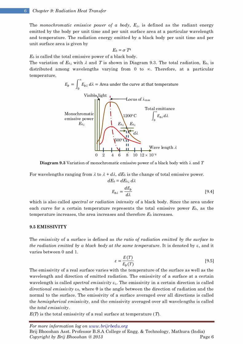
The monochromatic emissive power of a body, E, is defined as the radiant energy
emitted by the body per unit time and per unit surface area at a particular wavelength
and temperature. The radiation energy emitted by a black body per unit time and per
unit surface area is given by
Eb = T4
Eb is called the total emissive power of a black body.
The variation of Eb with and T is shown in Diagram 9.3. The total radiation, Eb, is
distributed among wavelengths varying from 0 to . Therefore, at a particular
temperature,
Diagram 9.3 Variation of monochromatic emissive power of a black body with and T
For wavelengths ranging from to + d, dEb is the change of total emissive power.
dEb = dEb d
which is also called spectral or radiation intensity of a black body. Since the area under
each curve for a certain temperature represents the total emissive power Eb, as the
temperature increases, the area increases and therefore Eb increases.
9.5 EMISSIVITY
The emissivity of a surface is defined as the ratio of radiation emitted by the surface to
the radiation emitted by a black body at the same temperature. It is denoted by , and it
varies between 0 and 1.
The emissivity of a real surface varies with the temperature of the surface as well as the
wavelength and direction of emitted radiation. The emissivity of a surface at a certain
wavelength is called spectral emissivity . The emissivity in a certain direction is called
directional emissivity θ, where θ is the angle between the direction of radiation and the
normal to the surface. The emissivity of a surface averaged over all directions is called
the hemispherical emissivity, and the emissivity averaged over all wavelengths is called
the total emissivity.
E(T) is the total emissivity of a real surface at temperature (T).
Wave length
(m)
Total emittance
Visible light Locus of max
1200C
Eb Eb
d
Monochromatic
emissive power
Eb
0 2 4 6 8 10 12 106
500C

For more information log on www.brijrbedu.org
Brij Bhooshan Asst. Professor B.S.A College of Engg. & Technology, Mathura (India)
Copyright by Brij Bhooshan @ 2013 Page 7
7 Heat and Mass Transfer By Brij Bhooshan
E(T) = ε(T)∙T4
Thus, Spectral emissivity or monochromatic emissivity is defined in a similar manner
where E(T) is the spectral or monochromatic emissive power of the real surface.
When the emissivity of the material does not change with temperature, it is called a
gray body. A gray body has a constant monochromatic emissivity , with respect to
wavelength as shown in Diagram (9.4).
Diagram 9.4 Emmissivities of real surface, gray body and black body
Thus, a gray body has a characteristic emissivity value (< 1) which does not vary with
temperature.
The monochromatic emissive power, , of a real surface can vary significantly from
black body emissive power, as illustrated in Diagram 9.5.
This is due to the fact that E = Eb. Since for the real surface is a characteristic of the
surface and not the temperature of the surface, the area under the real surface Eb curve
will not be a constant fraction of the area under the Eb curve as the temperature varies.
Diagram 9.5 comparison of emissive power of a black body, gray body and a real surface varying
with
9.6 KIRCHHOFF'S LAW
It’s sate that “The ratio of emissive power to absorptive power same for all surface at the
same temperature.”
Diagram 9.6 Energy exchange between a body and the enclosing wall
A small body of surface area A1 is placed in a hollow evacuated space kept at a constant
uniform temperature T (Diagram 9.6). After some time, the body will attain at steady
Hollow evacuated space kept at
constant uniform temperature
Small body of surface area A1 1
Monochromatic
emissive power
Eb
40
30
20
10
0 1 2 3 4 5 6
0 Wave length ()()
Real
surface
ε = ε = 0.61 (Gray body)
ε = ε = 1 (Black body)
Real surface
Gray body
0
1.0 Black body ( = 1.0)

For more information log on www.brijrbedu.org
Brij Bhooshan Asst. Professor B.S.A College of Engg. & Technology, Mathura (India)
Copyright by Brij Bhooshan @ 2013 Page 8
8 Chapter 9: Radiation Heat Transfer
state the same temperature as that of the interior of the space and thereafter will
radiate as much energy as it receives.
Let I be the radiant energy falling upon the body per unit time per unit surface area, E1
be the total emissive power of the body and, 1 be the absorptivity of the body.
At steady state,
Energy absorbed = Energy emitted
IA1 1 = E1 A1
Otherwise there would be an energy flow in to or out of the body which would raise or
lower its temperature.
If we replace the body in the enclosure with black body of the same shape and surface
area, and allow it to come to equilibrium which enclosure at the same temperature.
IA1 B = Eb A1
I = Eb/B [9.8]
From Eqns. (9.7) and (9.8), we have
ε = [9.9]
Equation (9.9) is Kirchhoff’s identity.
This is Kirchhoff’s law which states that the emissivity of the surface of a body is equal to
its absorptivity when the body is in thermal equilibrium with its surroundings.
A black body in addition to being a perfect absorber (B = 1) is also a perfect emitter (B
= 1) of radiant energy.
Kirchhoff’s law also holds for monochromatic radiation, for which
Therefore,
= ε [9.10]
Eq. (9.10) shows, the monochromatic absorptivity at the same wavelength.
Therefore, the monochromatic emissivity of a body is equal to the monochromatic
absorptivity at the same wavelength.
Now we know that
Then

For more information log on www.brijrbedu.org
Brij Bhooshan Asst. Professor B.S.A College of Engg. & Technology, Mathura (India)
Copyright by Brij Bhooshan @ 2013 Page 9
9 Heat and Mass Transfer By Brij Bhooshan
9.7 CONCEPT OF BLACK BODY
Black body is a substance which absorbs all the radiation incident on its surface. Ex.
Charcole, lamp black, etc.
Good absorbers are also good emitters in the state of thermal equilibrium.
A black body has the property of absorbing photons of all wave length. The radiation
incident of the body appears to black.
If a light ray is incident of the hole, then its fails to come out of the hole because it
suffers the multiple reflections in state that the enclosure hole is the black body
(Diagram 9.7).
Diagram 9.7 Black body cavity
Suppose the energy emitted from a portion of the surface in the cavity is Eb. After one
reflection, this becomes ρEb, after two reflections, ρ2Eb, etc. Let us suppose the
radiation leaving the hole of this cavity to be composed of rays which have been directly
radiated, reflected once, twice, etc.
Then the energy emitted from the hole is
E = εEb + ρεEb + ρ2 εEb + = εEb (1 + ρ + ρ2 + )
The energy streaming out from the hole is black body radiation.
9.8 PLANCK'S LAW OF RADIATION
Planck’s introduced the quantum concept in 1900 and with it the idea that radiation is
emitted not in a continuous energy state but in discrete amounts or quanta. The
intensity of radiation emitted by a black body, derived by Planck, is
where Ib is the intensity of radiation from a black body between wavelengths and +
d.
The total emissive power between wavelengths and +d is
Suppose
C1 = 2hc2 = 3.742 108 [Wμm4/m2]; C2 = hc/k = 1.4388 108 [μmk]
Then Eq. (9.14) will be
Isothermal
enclosure
3rd reflection and
partial absorption
2nd reflection and
partial absorption
1st reflection and
partial absorption
Hole Incident ray
For more information log on www.brijrbedu.org
Brij Bhooshan Asst. Professor B.S.A College of Engg. & Technology, Mathura (India)
Copyright by Brij Bhooshan @ 2013 Page 10
10 Chapter 9: Radiation Heat Transfer
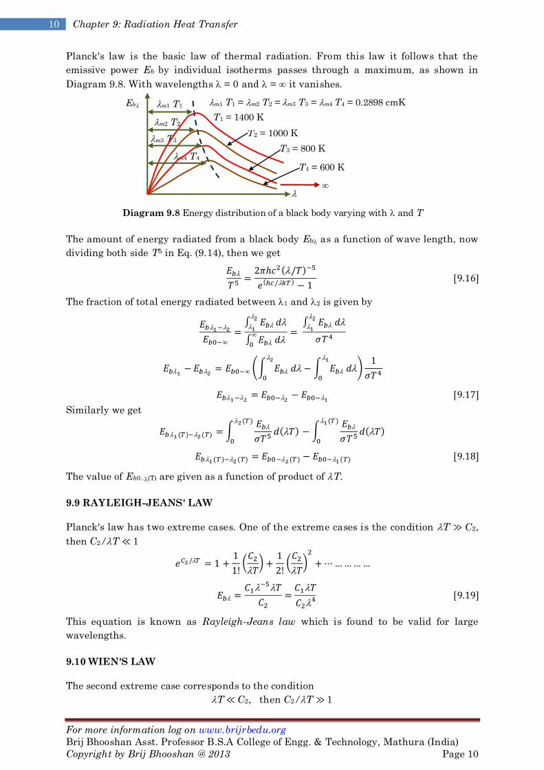
Planck's law is the basic law of thermal radiation. From this law it follows that the
emissive power Eb by individual isotherms passes through a maximum, as shown in
Diagram 9.8. With wavelengths = 0 and = it vanishes.
Diagram 9.8 Energy distribution of a black body varying with and T
The amount of energy radiated from a black body Eb as a function of wave length, now
dividing both side T5 in Eq. (9.14), then we get
The fraction of total energy radiated between 1 and 2 is given by
Similarly we get
The value of Eb0(T) are given as a function of product of T.
9.9 RAYLEIGH-JEANS' LAW
Planck's law has two extreme cases. One of the extreme cases is the condition T ≫ C2,
then C2/T ≪ 1
This equation is known as Rayleigh-Jeans law which is found to be valid for large
wavelengths.
9.10 WIEN'S LAW
The second extreme case corresponds to the condition
T ≪ C2, then C2/T ≫ 1
m1 T1 = m2 T2 = m3 T3 = m4 T4 = 0.2898 cmK Eb
m4 T4
m3 T3
m2 T2
m1 T1
=
T4 = 600 K
T3 = 800 K
T2 = 1000 K
T1 = 1400 K

For more information log on www.brijrbedu.org
Brij Bhooshan Asst. Professor B.S.A College of Engg. & Technology, Mathura (India)
Copyright by Brij Bhooshan @ 2013 Page 11
11 Heat and Mass Transfer By Brij Bhooshan
The unity present in the denominator of Eq. (9.15) can be neglected, and the
relationship becomes
This equation is known as Wien's law, which is found to be valid for short wavelengths.
9.11 WIEN'S DISPLACEMENT LAW
The maximum values of the emissive power Eb can be obtained by differentiating
Planck's equation (9.15) with respect to and equating it to zero.
Put C2 /T = x and rearranging
The solution of above equation is
max T = 2.898 103 mK [9.21]
This above equation is termed as Wien's displacement law. Here, max is the wavelength
at which Eb is the maximum at a particular temperature. The value of (Eb)max shifts
towards the shorter wavelengths with increasing temperature.
Diagram 9.9
The maximum emissive power of a black body can be found from Planck's law; = max is
replaced from Eq. (9.15).
(Eb)max = C3 T5 W/m3 [9.22]
where the constant C3 = 1.287 105 W/m3 K5. From Eq. (9.22) it follows that the
magnitude of (Eb)max proportional to the fifth power of the absolute temperature of the
body.
9.12 PLANCK'S LAW IN DIMENSIONLESS FORM
Its expressed in dimensionless form by using Eq. (9.22). Therefore,
Eb
2m 1m
T2
T1
Eb
T2 > T1
T2 T1

For more information log on www.brijrbedu.org
Brij Bhooshan Asst. Professor B.S.A College of Engg. & Technology, Mathura (India)
Copyright by Brij Bhooshan @ 2013 Page 12
12 Chapter 9: Radiation Heat Transfer
From Eqs. (9.23) and (9.24), the maximum of this relationship corresponds to the values
of
This is also equal to the ratio of area A1 to the total area under the curves at T (Diagram
9.11). Similarly, for the wavelength range between and 1 and 2, the fraction of
radiation at temperature T, as shown in Diagram 9.11 would be
Diagram 9.10 fraction of radiation in a range of wavelength expressed as area ratio
9.13 BLACK BODY RADIATION IN A CERTAIN RANGE OF WAVELENGTH
The fraction of total radiation f from a black body in the wavelength range of 0 at a
certain temperature T is given by Eq. (9.25).
From Eqns. (9.15) and (9.16),
This gives Eb/T5 are given as a function of product of T.
Again
Now using equation (9.27), then we have
Diagram 9.11 shows the graph of Eb/T5 vs T.
1 2
Eb
Eb
d
T
A1
A2

For more information log on www.brijrbedu.org
Brij Bhooshan Asst. Professor B.S.A College of Engg. & Technology, Mathura (India)
Copyright by Brij Bhooshan @ 2013 Page 13
13 Heat and Mass Transfer By Brij Bhooshan
Diagram 9.11 Total energy of black body radiation below T
At T = 1 K, the curve represents Eb vs . The area under the curve is equal to the
Stefan-Boltzmann constant. The fractional energy in the range of 1T and 2T given by
which also represents the area ratio which can be read from the scale at the top of
Diagram 9.11.
9.14 RADIATION FROM REAL SURFACES
A gray body is one the monochromatic emissivity of which has the same value at all
wavelengths. For a gray body, is independent of so that
= = ε =
even though the temperatures of the incident radiation and of the receiving surface are
not the same.
In general, however, the emissivity of real surfaces varies with wavelength. If the
variation of monochromatic emissivity with is known, the emissive power of the real
body can be found by plotting the product in Eb vs (Diagram 9.12).
Diagram 9.12 Variation of E with
An average emissivity of a real body can then be obtained from
Then
Since = E/Eb. If the real body is gray body, then the ratio Eg/Eb is constant for all
wavelengths.
Real surface,
Gray body = const.
T = const.
Black body ( = 1.0) T = const.
E
Eb
E
Eg
Real surface
E = εEb
E = εEb
(Gray body)
Black
body
Total energy
found below T
T d(T)
Total
area =
At T = 1
K
0.2898
cmK
Eb/T5

For more information log on www.brijrbedu.org
Brij Bhooshan Asst. Professor B.S.A College of Engg. & Technology, Mathura (India)
Copyright by Brij Bhooshan @ 2013 Page 14
14 Chapter 9: Radiation Heat Transfer
The total average absorptivity can be similarly obtained from the distribution of
monochromatic absorptivity .
If a plot of with is known, can be obtained from the above equation.
9.15 INTENSITY OF RADIATION
The intensity of radiation, I is defined as the rate of heat radiation in a given direction
from a surface per unit solid angle per unit area of the projection of the surface on a
plane normal to the direction of radiation (Diagram 9.13).
Diagram 9.14
A solid angle is defined as the ratio of the spherical surface enclosed by a cone, with its
vertex at the centre of the sphere, to the square of the radius of the sphere (Diagram
9.13). The solid angle subtended by the spherical surface dA at the centre would be
dA/r2, where r is the radius of the sphere. If dA = r2, the solid angle subtended is 1
steradian. The whole spherical surface subtends at the centre an angle of 4 steradian
or 1 steragon.
Let us consider the radiation emitted from an elemental black surface of area dA1 at the
temperature T (Diagram 9.14).
Diagram 9.14 Radiation from differential area in hemisphere
Energy will be radiated in all direction in the entire hemisphere.
Suppose that the spherical strip area dA of radius r sin θ and thickness r dθ which
subtends at the centre a solid angle of dA/r2.
where dq is the total energy emitts.
The amount of radiation dQ directed towards this area is
0 ≤ ≤ 2
0 ≤ θ ≤ /2
dA1 r
η
dθ
θ
d
r sin θ
dA
(b) Intensity of radiation
(a) Differential solid angle
r
dω = dA/r2 θ
η
dA
Emitting area
Intensity of
radiation I (θ, )
Solid angle dω
A1

For more information log on www.brijrbedu.org
Brij Bhooshan Asst. Professor B.S.A College of Engg. & Technology, Mathura (India)
Copyright by Brij Bhooshan @ 2013 Page 15
15 Heat and Mass Transfer By Brij Bhooshan
Total radiation in the entire hemisphere is
The emissive power of a black body is times the intensity of the emitted radiation.
Thus, the intensity I depends only on temperature T.
The total emissive power per unit area will be, if the surface does not radiate diffusely,
then
Lambert's Cosine Law
The law states that the total emissive power Eθ from a radiating plane surface in any
direction is directly proportional to the cosine of angle of emission.
Eθ = E cos θ [9.36]
9.16 RADIATION HEAT TRANSFER EXCHANGE BETWEEN TWO BLACK
BODIES
The radiant heat exchange between two bodies depends upon
1. The views the surfaces have of each other, i.e. how they "see" each other.
2. Their emitting and absorbing characteristics and
3. The medium that intervenes the two bodies.
Let us assume that the two bodies are black and the medium in nonparticipating in the
energy exchange.
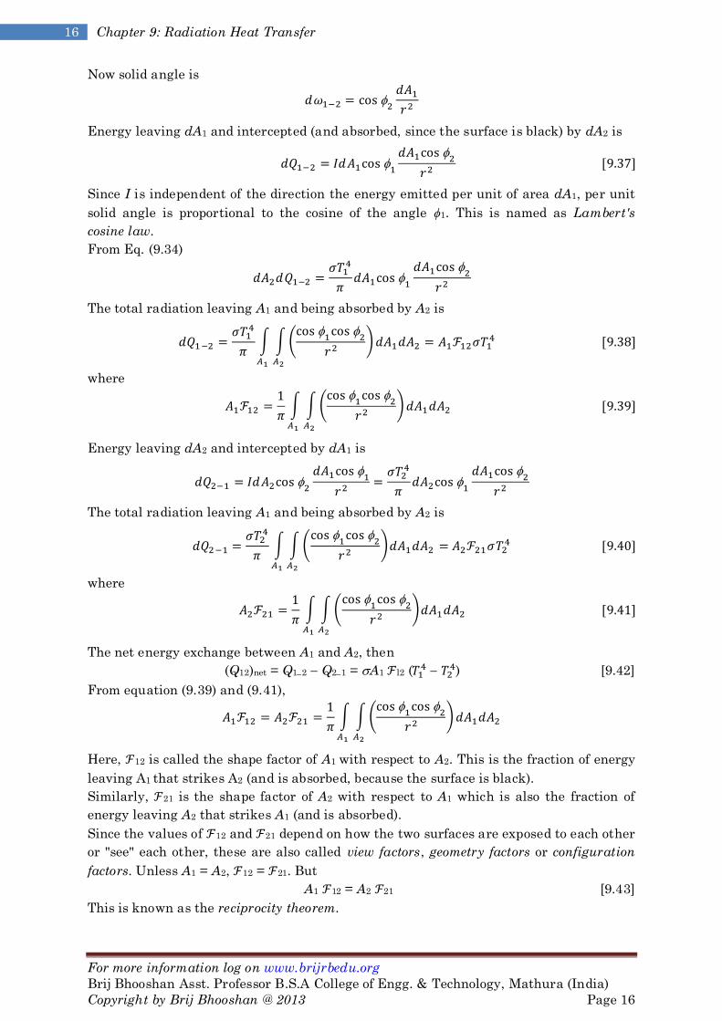
Suppose that the area elements dA1 and dA2 on the two surfaces (Diagram 9.15). The
distance between them is r and the angles made by the normals to the two area
elements with the line joining them are ϕ1 and ϕ2 respectively. The projected area of dA1
in the direction of radiation is dA1 cos ϕ1.
Diagram 9.15 Radiant heat exchange between two surfaces
r
A1
N
1
N2
A2
dA1
dA2
For more information log on www.brijrbedu.org
Brij Bhooshan Asst. Professor B.S.A College of Engg. & Technology, Mathura (India)
Copyright by Brij Bhooshan @ 2013 Page 16
16 Chapter 9: Radiation Heat Transfer
Now solid angle is
Energy leaving dA1 and intercepted (and absorbed, since the surface is black) by dA2 is
Since I is independent of the direction the energy emitted per unit of area dA1, per unit
solid angle is proportional to the cosine of the angle ϕ1. This is named as Lambert's
cosine law.
From Eq. (9.34)
The total radiation leaving A1 and being absorbed by A2 is
where
Energy leaving dA2 and intercepted by dA1 is
The total radiation leaving A1 and being absorbed by A2 is
where
The net energy exchange between A1 and A2, then
(Q12)net = Q12 Q21 = A1 l2 (
) [9.42]
From equation (9.39) and (9.41),
Here, 12 is called the shape factor of A1 with respect to A2. This is the fraction of energy
leaving A1 that strikes A2 (and is absorbed, because the surface is black).
Similarly, 21 is the shape factor of A2 with respect to A1 which is also the fraction of
energy leaving A2 that strikes A1 (and is absorbed).
Since the values of 12 and 21 depend on how the two surfaces are exposed to each other
or "see" each other, these are also called view factors, geometry factors or configuration
factors. Unless A1 = A2, 12 = 21. But
A1 12 = A2 21 [9.43]
This is known as the reciprocity theorem.

For more information log on www.brijrbedu.org
Brij Bhooshan Asst. Professor B.S.A College of Engg. & Technology, Mathura (India)
Copyright by Brij Bhooshan @ 2013 Page 17
17 Heat and Mass Transfer By Brij Bhooshan
Application 9.1: Consider the radiation from the small area dA1 to the flat disk A2, as
shown in Diagram 9.16. The element of area dA2 is chosen as the circular ring of radius
x.
Diagram 9.16 Radiation from a small-area element to a disk.
Solution: From Diagram 9.16, dA2 = 2 x.dx, and 1 = 2
Now shape factor is
Put
9.17 SHAPE FACTOR ALGEBRA
Consider an enclosure consisting of n surface as shown in Diagram 9.17. The energy
leaving the surface i must be intercepted by some surface of the enclosure, including i
itself if it is concave. That is
Diagram 9.17 Enclosure of black surface
If the surface j is subdivided in to m subsurface as shown in diagram, then
ii is the self-viewing factor and it is non-zero only for concave surfaces.
1
2
3
1
2
L
dA1 R =
R x

For more information log on www.brijrbedu.org
Brij Bhooshan Asst. Professor B.S.A College of Engg. & Technology, Mathura (India)
Copyright by Brij Bhooshan @ 2013 Page 18
18 Chapter 9: Radiation Heat Transfer
In addition, the reciprocity theorem holds true for any two surfaces of the enclosure.
The decomposition of one or both the surfaces into subdivisions produces a combination
of geometrical configurations for which the shape factor is easily determined. Of the two
surfaces A1 and A2, if A1 is subdivided into two parts A3 and A4, then the radiant heat
exchange between A1 and A2 is
If the surfaces are black,
Since, T1 = T2 = T3, then
The radiant exchange from A2 to Al
For two large plate are placed at parallel then
If surfaces are flat or convex the shape factor with respect to itself is zero.
Application 9.2: Suppose a sphere of surface area A1 is completely enclosed by an
irregular surface of area A2 as shown in Diagram 9.18. Find the shape factor.
Diagram 9.18
Solution: The energy conversation
The spherical surface is convex and hence itself factor is given 11 = 0.
From reciprocity theorem
Energy conservation for surface A2 is
Application 9.3: Suppose an enclosure of three non-concave surfaces as shown in
Diagram 9.19. Find the shape factor.
Diagram 9.19
Solution: From energy conversation to the surfaces 1, 2 and 3 gives
1 2
3
For more information log on www.brijrbedu.org
Brij Bhooshan Asst. Professor B.S.A College of Engg. & Technology, Mathura (India)
Copyright by Brij Bhooshan @ 2013 Page 19
19 Heat and Mass Transfer By Brij Bhooshan
12 + 13 = 1 (a)
21 + 23 = 1 (b)
31 + 32 = 1 (c)
From reciprocity theorem
After solving equation (a) – (f), we get
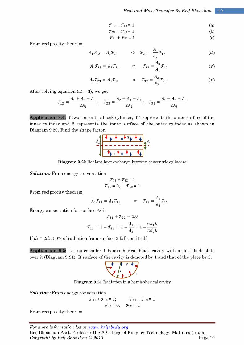
Application 9.4: If two concentric block cylinder, if 1 represents the outer surface of the
inner cylinder and 2 represents the inner surface of the outer cylinder as shown in
Diagram 9.20. Find the shape factor.
Diagram 9.20 Radiant heat exchange between concentric cylinders
Solution: From energy conversation
11 + 12 = 1
11 = 0, 12 = 1
From reciprocity theorem
Energy conservation for surface A2 is
If d1 = 2d2, 50% of radiation from surface 2 falls on itself.
Application 9.5: Let us consider 1 hemispherical black cavity with a flat black plate
over it (Diagram 9.21). If surface of the cavity is denoted by 1 and that of the plate by 2.
Diagram 9.21 Radiation in a hemispherical cavity
Solution: From energy conversation
11 + 12 = 1; 21 + 22 = 1
22 = 0, 21 = 1
From reciprocity theorem
2
1
1
2

For more information log on www.brijrbedu.org
Brij Bhooshan Asst. Professor B.S.A College of Engg. & Technology, Mathura (India)
Copyright by Brij Bhooshan @ 2013 Page 20
20 Chapter 9: Radiation Heat Transfer
Therefore 50% of radiation emitted from the hemispherical surface is striking the
surface itself, and is absorbed.
Application 9.6: Consider the surface 1, 2, 3 as shown in Diagram 9.22. Find the shape
factor 13 in terms of the known shape factor for perpendicular rectangles with a
common edge.
Diagram 9.22
Solution: Suppose that the shape factor for radiation from A3 to the combined area A1,2
is desired. This shape factor must be given very simply as
3−1,2 = 3−1 + 3−2 [a]
that is, the total shape factor is the sum of its parts. We could also write Equation (a) as
A3 3−1,2 = A3 3−1 + A3 3−2 [b]
and making use of the reciprocity relations
A3 3−1,2 = A1,2 1,2−3
A3 3−1 = A1 1−3
A3 3−2 = A2 2−3
the expression could be rewritten
A1,2 1,2−3 = A1 1−3 + A2 2−3 [c]
which simply states that the total radiation arriving at surface 3 is the sum of the
radiations from surfaces 1 and 2.
Application 9.7: Suppose we wish to determine the shape factor 1−3 for the surfaces in
Diagram 9.23 in terms of known shape factors for perpendicular rectangles with a
common edge.
Diagram 9.23
Solution: We may write
1−2,3 = 1−2 + 1−3 [a]
1−3 = 1−2,3 + 1−2 [b]
in accordance with Equation (a)
A1 1,2−3 = A1 1−2 + A1 1−3 [c]

For more information log on www.brijrbedu.org
Brij Bhooshan Asst. Professor B.S.A College of Engg. & Technology, Mathura (India)
Copyright by Brij Bhooshan @ 2013 Page 21
21 Heat and Mass Transfer By Brij Bhooshan
From reciprocity relations
A1 1−2,3 = A2,3 2,3−1 [d]
A1 1−2 = A2 2−1 [e]
A1 1−3 = A3 3−1 [f]
After solving we get
A2,3 2,3−1 = A2 2−1 + A3 3−1
Application 9.8: Determine the shape factor 1−4 for the surfaces in Diagram 9.24 in
terms of known shape factors for perpendicular rectangles with a common edge.
Diagram 9.24
Solution: Let us call the combined surface A1 and A2 as B and the combined surface A3
and A4 as C.
Then AB = A1-2, AC = A3-4.
AB B−C = A1 1−C + A2 2−C [a]
Since radiation leaving the surface B is the sum of radiation leaving the surface A1 and
A2, A1 1−C will be
A1 1−C = A1 1−3 + A1 1−4 [b]
AB B−3 = A1 1−3 + A2 2−3 [c]
A1 1−3 = AB B−3 – A2 2−3 = A1–2 1,2−3 – A2 2−3 [d]
From equation (b) and (d), then we have
A1 1−C = A1 1−3,4 = A1,2 1,2−3 – A2 2−3 + A1 1−4 [e]
From equation (e) and (a), then we have
AB B−C = A1–2 1,2−3,4 = A1,2 1,2−3 – A2 2−3 + A1 1−4 + A2 2−3,4
Application 9.9: Find the shape factor A1,2 by using the Hottels cross strings method
for surface as shown in Diagram 9.25.
Diagram 9.25
Solution: From geometry
D
D
C
B A
C
B

For more information log on www.brijrbedu.org
Brij Bhooshan Asst. Professor B.S.A College of Engg. & Technology, Mathura (India)
Copyright by Brij Bhooshan @ 2013 Page 22
22 Chapter 9: Radiation Heat Transfer
Using the Hottel’s cross-link strings formula
2L1 12 = Sum of length of the two crossed link Sum of length of the uncrossed link [9.47]
9.18 ELECTRICAL ANALOGY OF RADIANT EXCHANGE IN BLACK
ENCLOSURE
We know that
Between any two black surface the radiant heat exchange rate given the or rate of
radiant flux between two black surface
For surface 1 and any other surface, designated i, in a black enclosure the radiant
exchange
For surface 1 views n other surfaces,
From equation (9.48)
Diagram 9.26 Electrical analogy of radiative energy transfer between two black surfaces 1 & 2.
where (Eb1 – Eb2) is the driving force or potential between the two nodes 1 and 2 for
radiative energy transfer and 1/A1 1–2 is the resistance. The corresponding network is
given in Diagram 9.26.
Diagram 9.27 Radiative flux between the walls of a four wall black enclosure
4
3
2
1
2 1
For more information log on www.brijrbedu.org
Brij Bhooshan Asst. Professor B.S.A College of Engg. & Technology, Mathura (India)
Copyright by Brij Bhooshan @ 2013 Page 23
23 Heat and Mass Transfer By Brij Bhooshan
For radiative flux between the four walls of a black enclosure (Diagram 9.27),
The equivalent network is shown in Diagram 9.27.
From an analogous Kirchhoff s law, the net heat flux leaving node point 1 is
which is identical with Eq. (9.52).
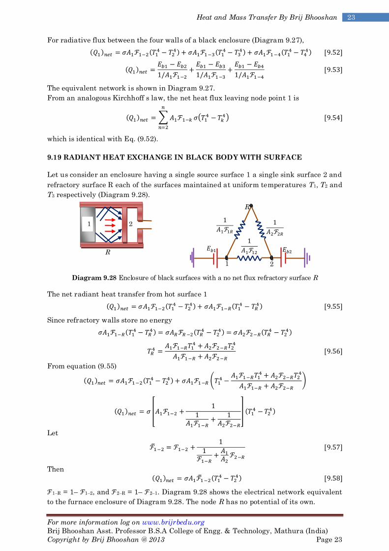
9.19 RADIANT HEAT EXCHANGE IN BLACK BODY WITH SURFACE
Let us consider an enclosure having a single source surface 1 a single sink surface 2 and
refractory surface R each of the surfaces maintained at uniform temperatures T1, T2 and
T3 respectively (Diagram 9.28).
Diagram 9.28 Enclosure of black surfaces with a no net flux refractory surface R
The net radiant heat transfer from hot surface 1
Since refractory walls store no energy
From equation (9.55)
Let
Then
1–R = 1– 1–2, and 2–R = 1– 2–1. Diagram 9.28 shows the electrical network equivalent
to the furnace enclosure of Diagram 9.28. The node R has no potential of its own.
R
2 1
R
2 1

For more information log on www.brijrbedu.org
Brij Bhooshan Asst. Professor B.S.A College of Engg. & Technology, Mathura (India)
Copyright by Brij Bhooshan @ 2013 Page 24
24 Chapter 9: Radiation Heat Transfer
Now
Using equation (9.57)
If A1 = A2, then
If the surface 2 does not "see" the surface 1, there is no direct incident radiation on
surface 2 from surface 1, then
If A1 = A2, and 1–2 = 0 then
Equations (9.57) and (9.58) solve many furnace problems. But these are in error because
the temperatures of the surfaces are not uniform in practice. Hottel extended this type of
analysis to multisurface cases, each surface being at a uniform temperature.
9.20 RADIATION HEAT TRANSFER BETWEEN GRAY BODIES
Calculation of radiant heat exchange between black surfaces is relatively easy, since all
the radiant energy which strikes a surface is absorbed. Once the geometrical shape
factor has been determined, the calculation of heat transfer is quite simple. This is,
however, not the case with nonblack bodies, since all the radiation striking a surface is
not absorbed, some part is reflected. Also the emissivities and absorptivities are not
uniform in all directions and for all wavelengths. The problem is somewhat simplified if
the bodies are considered gray in which case and are constant over the entire spectrum
of wavelength and so their average values are equal irrespective of temperatures, i.e.
= .
Since the transmissivity is zero for solid bodies, + ρ = 1 and for a gray body, the
reflectivity of the surface is considered as an additional parameter.
Radiant Exchange between Two Small Gray Bodies
Let us consider two gray bodies, represented by suffix 1 and 2, having emissivity’s 1 and
2. Let us suppose that the bodies are small compared with the distance between them.
It may thus be assumed that of the radiation unabsorbed and reflected diffusely at each
surface, a negligible proportion returns to the original emitting body.
The energy emitted by the body 1 is 1A1(T1)4 of which 12[1A1(T1)4] is incident on the
second body, of which 2 12[1A1(T1)4] is absorbed. Since the bodies are gray, 2 = 2 and
energy transfer from 1 to 2 is

For more information log on www.brijrbedu.org
Brij Bhooshan Asst. Professor B.S.A College of Engg. & Technology, Mathura (India)
Copyright by Brij Bhooshan @ 2013 Page 25
25 Heat and Mass Transfer By Brij Bhooshan
Q12 = A1 12 12
Similarly
Q21 = A2 12 21
Therefore, the net radiant heat transfer between the two bodies is
(Q12)net = A1 12 12 (
) [9.62]
The equivalent emissivity eq of two small gray bodies is
eq = 1 2 [9.63]
This is also called the view factor 12 for gray bodies
12 = 1 2 [9.64]
In practice, of course, a portion of the reflected radiation from each is returned to the
other body and reradiated so that the true equivalent emissivity eq or l2 is greater than
that given by Eq. (9.63), which gives, in fact, the least possible value.
Radiant Exchange between Two Small Gray Bodies
The radiant interchange between two infinite parallel gray planes involves no geometry
factor, since l2 = 21 = 1.0.
Let us consider two gray planes, as shown in Diagram 9.29. For gray surfaces, according
to Kirchhoff’s law = and ρ = 1–. Surface 1 emits E1 per unit time and area. Surface
2 absorbs the fraction 2E1 and reflects (1– 2)E1 back towards A1. The net heat
transferred per unit of surface 1 to 2 is the emission E1 minus the fraction of E1 and E2
which is ultimately absorbed by surface 1 after successive reflections. Therefore,
Diagram 9.29 Radiant heat exchange between two infinite parallel gray planes
Suppose z = (1– 1)(1– 2), then
Put = , and 2 = 2, then we have

For more information log on www.brijrbedu.org
Brij Bhooshan Asst. Professor B.S.A College of Engg. & Technology, Mathura (India)
Copyright by Brij Bhooshan @ 2013 Page 26
26 Chapter 9: Radiation Heat Transfer
Similarly we get the radiant which leaves surface 2 is
The net heat transferred per unit time of surface 1 to 2 is
Now we know that
where
where 12 is the view factor for gray bodies.
Infinite Long Concentric Cylinder
Consider a infinite long concentric cylinder as shown in Diagram 9.30.
Diagram 9.30 Infinite long concentric cylinders
Suppose the energy emitted per unit area by inner cylinder.
Now we know that 12 = 1, and
Inner cylinder emits energy = E1,
Outer cylinder absorb energy is
Outer cylinder reflect energy is
Inner cylinder absorb energy is
Inner cylinder reflects energy is
Energy absorbed by inner cylinder on the second reflection is
Heat lost by the inner cylinder per unit area is given by
Outer cylinder A2, ε2, T2
Inner cylinder A1, ε1, T1

For more information log on www.brijrbedu.org
Brij Bhooshan Asst. Professor B.S.A College of Engg. & Technology, Mathura (India)
Copyright by Brij Bhooshan @ 2013 Page 27
27 Heat and Mass Transfer By Brij Bhooshan
Similarly heat lost by the outer cylinder per unit area is given by
Net radiation heat transfer between the inner and outer concentric cylinder is
Now we know that
where
Heat Exchange Small Body in a Large Enclosure
Suppose that all the radiations emitted by the small body would be intercepted by the
outer enclosure. Then 12 = 1.
Energy emitted by small body 1 and absorbed by the outer large enclosure 2 is
Energy emitted by enclosure 2 is
Energy incident upon the small body 1 is
Energy absorbed by the small body 1 is
Net radiation heat transfer between the small body 1 and outer large enclosure 2 is

For more information log on www.brijrbedu.org
Brij Bhooshan Asst. Professor B.S.A College of Engg. & Technology, Mathura (India)
Copyright by Brij Bhooshan @ 2013 Page 28
28 Chapter 9: Radiation Heat Transfer
If T1 = T2, and Q1–2, then
For gray surface
9.21 RADIOSITY AND IRRADIATION
In calculating radiant heat transfer from gray surfaces, two terms will now be
introduced. Radiosity is the term used to indicate the total radiant energy leaving a
surface per unit time and per unit surface area. It is denoted by the symbol J. This
quantity differs from the emissive power in that the radiosity includes reflected energy
as well as the original emission, regardless of any directional dependence or spectral
preference.
Irradiation is the term used to denote the total radiation incident on a surface per unit
time and per unit surface area. It is denoted by the symbol G.
Diagram 9.31 (a) Surface energy balance for opaque material; (b) Radiosity and irradiation in a
gray body; (c) element representing “surface resistance” in the radiation-network method
Now the term radiosity is the sum of the energy emitted and the energy reflected, when
no energy is transmitted as shown in Diagram 9.31(b), so that
The net energy leaving the surface is the difference between the radiosity and
irradiation
From Eq. (9.71),
Substituting in Eq. (9.72),
Equation (9.73) provides a basis for network representation of the gray enclosure. If the
numerator on the right side is considered as the potential difference, the denominator as
the "surface resistance” to radiation heat transfer and the heat flow as current, then a
network element could be drawn, as shown in Diagram 9.31(c).
Let us now consider the exchange of radiant energy by two surfaces A1 and A2 as shown
in Diagram 9.32(a).
(a) (b)
(c)
Gray
body

For more information log on www.brijrbedu.org
Brij Bhooshan Asst. Professor B.S.A College of Engg. & Technology, Mathura (India)
Copyright by Brij Bhooshan @ 2013 Page 29
29 Heat and Mass Transfer By Brij Bhooshan
Diagram 9.32 (a) Radiant interchange between two gray surfaces; (b) Element representing
"space resistance" in radiation network method
The total radiation which leaves the surface 1, the amount that reaches surface 2 is
J1A1 12, and of the total energy leaving surface 2, the amount that reaches surface 1 is
J2A2 21.
The net energy interchange between two surfaces is
Since A1 12 = A2 21,
We may thus construct a network element (Diagram 32(b)) which represents Eq. (9.74).
The denominator 1/(A1 12) is called the "space resistance" and the numerator (J1 – J2) is
the potential difference.
9.22 RADIATION NETWORK FOR GRAY SURFACES EXCHANGING ENERGY
To construct a network for a particular radiation heat transfer problem, we only have to
connect a "surface resistance", (1–)/A, to each surface and a "space resistance",
1/(Ax xy), between the radiosity potentials.
Diagram 9.33 shows a network which represents two surfaces exchanging radiative
energy with each other.
Diagram 9.33 Radiation network for two surfaces which see each other and nothing else
The net heat transfer would be given by dividing the overall potential difference with
the sum of the resistances.
If 1/(A1 12) is used to represent the overall resistance or A1 12 as the overall inductance,
then
where
or
(b) (a)
1 2

For more information log on www.brijrbedu.org
Brij Bhooshan Asst. Professor B.S.A College of Engg. & Technology, Mathura (India)
Copyright by Brij Bhooshan @ 2013 Page 30
30 Chapter 9: Radiation Heat Transfer
For a three-body problem, the radiation network is shown in Diagram 9.34.
Diagram 9.34 Radiation network for three surfaces which see each other and nothing else
The radiation heat exchange between body 1 and body 2 would be
and that between body 1 and body 3,
The values of radiosities have to be calculated for determining the heat flows in a
problem of this type. Kirchhoff s law on electrical dc network theory which states that
the algebraic sum of the currents entering a node is zero is applied.
The network method can be conveniently used to solve the problem of energy exchange
between two gray surfaces connected by a nonconducting and reradiating surface to
form an enclosure (Diagram 9.28). Diagram 9.28 will get modified, since unlike black
surfaces, gray surfaces have surface resistance. The corresponding radiation network for
the system is shown in Diagram 9.35.
Diagram 9.35 Radiation network for two gray surfaces enclosed by a third surface which is
nonconducting and reradiating
Node JR is not connected to any surface resistance, since the surface 1 has no source of
its own and it only reflects energy. It is termed as floating node. Now
Similarly, 2R = 1 – 21,
The network above (Diagram 9.35) is a simple series parallel system and may be solved
to compute the heat flow.
Let R’ is the sum of the resistances 1/[A1(1 – 21)] and 1/[A2(1 – 21)], which are in series.
For more information log on www.brijrbedu.org
Brij Bhooshan Asst. Professor B.S.A College of Engg. & Technology, Mathura (India)
Copyright by Brij Bhooshan @ 2013 Page 31
31 Heat and Mass Transfer By Brij Bhooshan
Let Req be the equivalent resistance of the parallel resistances of R’ and 1/[A1 12], so that
The total resistance Rt offered to heat flow is
Therefore, the heat flow
where
which is the same as Eq. (9.59).
(i) If the surfaces are black, 1 = 1, 2 = l, for which
(ii) For infinite parallel planes, A1 and A2 are equal and radiation shape factor 12 =
21 = 1, since all the radiation leaving one plane reaches the other. Equation
(9.82) reduces to
where
This can also be obtained from Eq. (9.78).
(iii) For two long concentric cylinders as shown in Diagram 9.36, 12 = 1, Eq. (9.82)
becomes

For more information log on www.brijrbedu.org
Brij Bhooshan Asst. Professor B.S.A College of Engg. & Technology, Mathura (India)
Copyright by Brij Bhooshan @ 2013 Page 32
32 Chapter 9: Radiation Heat Transfer
Diagram 9.36 Radiation interchange between two concentric surfaces
where
This can also be obtained directly from Eq. (9.78).
If A1 = d1L and A2 = d2L,
where d1 and d2 are the diameters of the inner and outer cylinder respectively,
(iv) Equations (9.85) and (9.86) would also hold good for concentric spheres, for
which
where r1 and r2 are the radii of the inner and outer spheres.
(v) When a small body is enclosed by a large body, A1/A2 ~0, and 12 = 1, where
suffix 1 stands for the small body, Eq. (9.78) reduces to
which can be used to estimate the radiation energy loss from a hot object in a large
room.
For gray enclosures, any of the three network circuits may represent them Diagram
9.37.
The overall conductance is A1 12 and the overall resistance is
So that
If no radiating surfaces exist, then ’12 = 12 = 1.

For more information log on www.brijrbedu.org
Brij Bhooshan Asst. Professor B.S.A College of Engg. & Technology, Mathura (India)
Copyright by Brij Bhooshan @ 2013 Page 33
33 Heat and Mass Transfer By Brij Bhooshan
Diagram 9.37 Electrical analog of enclosure of gray surfaces with a refractory surface
For the network (Diagram 9.37), it is clear that the following equation is an alternative
form of the equation
where
If A1 and A2 do not see each other, 12 = 0. Therefore, from Eq. (9.84)
From Eq. (9.91),
Even if the two surfaces do not see each other, still they receive energy via the
reradiating surface connected between them.
If the temperature of each type of enclosure is not uniform, the surfaces are then to be
divided into a number of parts, each of which may be considered to have a uniform
temperature. This would result in a number of source and sink surfaces and of no-net-
flux or reradiating surfaces.
9.23 HOTTEL’S CROSSED STRING METHOD
Let us consider the geometry as shown in Diagram 9.38 and find the shape factor 12
between surfaces 1 and 2. Let us connect the end points with tightly stretched strings
indicated by dashed lines.
If we consider the triangle ABD,
By reciprocity theorem,
R
2 1

For more information log on www.brijrbedu.org
Brij Bhooshan Asst. Professor B.S.A College of Engg. & Technology, Mathura (India)
Copyright by Brij Bhooshan @ 2013 Page 34
34 Chapter 9: Radiation Heat Transfer
Diagram 9.38 Determination of shape factor 12 by using the crossed-string method
Using equations (9.93) and (9.94)
Similarly
Now
In terms of lengths of strings,
instead of areas, Hottel’s cross-string method can thus be expressed as
9.24 RADIATION SHIELDS
Radiation heat transfer between two surfaces may be reduced either by using the
materials which are highly reflective or by introducing radiation shields between them.
Diagram 9.39(a) shows two infinite parallel gray planes interchanging radiative energy
between them with and without a radiation shield.
6
5
4
3 2
1
A
C
B
D

For more information log on www.brijrbedu.org
Brij Bhooshan Asst. Professor B.S.A College of Engg. & Technology, Mathura (India)
Copyright by Brij Bhooshan @ 2013 Page 35
35 Heat and Mass Transfer By Brij Bhooshan
Diagram 9.39 (a) Radiation between parallel infinite planes with and without radiation shield
(b) Radiation network for two parallel planes separated by one radiation shield
For the case with a radiation shield between the surfaces, at equilibrium
where T3 is the equilibrium temperature of the shield. If T3 is known, the heat transfer
rate can easily be calculated. The radiation network with one shield is shown in
Diagram 9.39(b).
If the two parallel planes are of equal emissivity ,
If the third plane placed between them also has the same emissivity, at equilibrium
At thermal equilibrium Q13/A = Q32/A, therefore
Now using equations (9.100) and (9.101), then we have
Now using equations (9.99) and (9.102), then we have
By the use of one radiation shield, the net radiant heat transfer is reduced by 50%. The
position of the shield so long as it does not touch either of the planes does not alter its
effectiveness.
Generalization:
If N shields are placed between the two planes 1 and 2, there would be (2N + 2) "surface
resistances", two for each shield and one for each heat transfer surface, and (N + 1)
"space resistances" (which would all be unity).
The total assistance would thus be
(b)
With
shield
Without
shield
1 2 3 2 1 (a)
Q/A

For more information log on www.brijrbedu.org
Brij Bhooshan Asst. Professor B.S.A College of Engg. & Technology, Mathura (India)
Copyright by Brij Bhooshan @ 2013 Page 36
36 Chapter 9: Radiation Heat Transfer
The resistance when no shield is present is
The resistance with the shields in place is (N+1) times as large as when the shields are
absent. Thus
For cylindrical radiation shield
9.25 RADIATION ERROR IN HIGH TEMPERATURE MEASUREMENT
If the temperature of a high temperature gas stream is measured by the insertion of a
thermometer or thermocouple, the effects of the radiant exchange between the pipe
walls and the temperature sensing element introduce considerable error.
Diagram 9.40 Gas temperature measurement with (a) a bare thermocouple and (b) a shielded
thermocouple
If Tg is the gas temperature to be measured and Tc is the measured temperature at
steady state, the heat transfer by convection from gas to the thermocouple is equal to
the heat transfer by radiation from thermocouple to the wall (Diagram 9.40(a)), so that
where cw = c, the emissivity of the thermocouple which is very small compared to the
enclosing wall, and Ac is the area of the thermocouple. Here, (Tg – Tc) is the
thermocouple error.
When the couple is shielded, this error is considerably reduced. At steady state, (i) the
heat transfer by convection from gas to couple is equal to that by radiation from couple
to shield and (ii) the heat transfer by convection from gas to shield and that by radiation
from couple to shield are equal to heat transfer by radiation from shield to wall
(Diagram 9.40(b)).
where
Ts is the equilibrium temperature of the shield, As is the shield surface area and s is the
emissivity of the shield. Since heat is transferred by convection from gas to both sides of
the shield, the total surface area of the shield is 2As, as provided in the first term of Eq.
(a)
Gas
Gas
Shield (b)

For more information log on www.brijrbedu.org
Brij Bhooshan Asst. Professor B.S.A College of Engg. & Technology, Mathura (India)
Copyright by Brij Bhooshan @ 2013 Page 37
37 Heat and Mass Transfer By Brij Bhooshan
(9.107). Assuming a value of Ts and solving for Tg from Eqs. (9.106) and (9.107) by trial
and error, the true gas temperature can be computed.
9.26 RADIATION FROM CAVITIES
The emission of radiant energy from cavities of regular geometrical shapes (Diagram
9.41) can be estimated.
Diagram 9.41 Radiant emission from cavities
Let us consider the conical cavity, as shown in Diagram 9.41(a), which is of diameter D,
height H, lateral length L, semi-vertex angle and surface area A1. The temperature T1
of the surface is uniform. Part of the radiation from the surface falls on itself, of which a
portion is absorbed and the remainder is reflected.
Rate of emission from the surface
Of this, the amount falling on A1 and absorbed by it
where 11 is the shape factor of the conical surface with respect to itself.
The amount reflected
Of this reflected energy, quantity falling on A1 and absorbed
Reflected
Absorbed
Reflected
and so on
Net rate of emission from the surface
Q = Total emission rate – Total absorption rate
(c) Cylindrical cavity (b) Hemispherical cavity
(a) Conical cavity
D
H
D
R
H
D

For more information log on www.brijrbedu.org
Brij Bhooshan Asst. Professor B.S.A College of Engg. & Technology, Mathura (India)
Copyright by Brij Bhooshan @ 2013 Page 38
38 Chapter 9: Radiation Heat Transfer
Let us consider an imaginary flat surface A2 closing the cavity (Diagram 9.42). Since A1
and A2 together form an enclosure,
Diagram 9.42 Conical cavity with a flat plate on top
Since 22 = 0, 21 = 1.
Now
From Diagram 9.42,
Surface area of cone
Now using equation (9.108)
Put for
Similarly, expressions for radiant emissions from cylindrical and hemispherical cavities
can be obtained.
9.27 APPARENT EMISSIVITY OF A CAVITY
Consider the cavity shown in Diagram 9.43 having an internal concave surface area A i
and emissivity i radiating out through the opening with area A0. The cavity exchanges
radiant energy with a surrounding at Ts having an area that is large compared to the
area of the opening.
If one considers the imaginary surface A0 covering the opening and exchanging heat
with Ai we have 0i = 1.0
D
H L
dx
x
r

For more information log on www.brijrbedu.org
Brij Bhooshan Asst. Professor B.S.A College of Engg. & Technology, Mathura (India)
Copyright by Brij Bhooshan @ 2013 Page 39
39 Heat and Mass Transfer By Brij Bhooshan
Diagram 9.43 Apparent emissivity of cavity
and, from reciprocity,
But, i0 = is so that
The net radiant exchange of surface Ai with the large enclosure As is given by
and the net radiant energy exchange of an imaginary surface A0 having an apparent
emissivity a with the large surroundings is given by
for A0 at the same temperature at the cavity surface Ai.
Now using equations (9.111), (9.112) and (9.113), we have
We can observe the following behavior for a in limiting cases:
a = i for A0 =Ai or no cavity at all
And a →1.0 for Ai >> A0.
9.28 THE RADIATION HEAT-TRANSFER COEFFICIENT
Frequently in engineering analysis, convection and radiation occur simultaneously
rather than as isolated phenomena. An important approximation in such cases is the
linearization of the radiation contribution so that
Qtotal = Qconvection + Qradiation
htotal = hconvection + hradiation
where
In terms of reference temperature TR,
Here TR is a reference temperature, and T1 and T2 are the respective surface
temperatures. In effect, equation (9.116) represents a straight-line approximation to the
radiant heat transfer as illustrated in Diagram 9.44.
≫ Surrounding Ts

For more information log on www.brijrbedu.org
Brij Bhooshan Asst. Professor B.S.A College of Engg. & Technology, Mathura (India)
Copyright by Brij Bhooshan @ 2013 Page 40
40 Chapter 9: Radiation Heat Transfer
Diagram 9.44 Tangent approximation for hr
The factor, , accounts for geometry and surface condition of the radiating and
absorbing surface.
By constructing a tangent to the relation curve at T = T1, the following relations are
obtained for hr and TR:
and
9.29 RADIATION FROM GASES AND VAPOURS
Gases such as oxygen, nitrogen, hydrogen, dry air, etc. are transparent to thermal
radiation, i.e. these gases neither emit nor absorb radiant energy at the temperature of
interest. On the other hand, some gases and vapours such as CO2, CO, H2O, SO2, NH3,
hyrocarbons, etc. absorb and emit radiant energy significantly. Of these gases, CO2 and
H2O vapour are the most important so far as the atmosphere and the industrial furnaces
are concerned.
Diagram 9.45 Emission and absorption bands of gas radiation
There are, however, certain differences between radiation from gases and that from
solids.
(1) Solids radiate and absorb energy at all wavelengths over the entire spectrum
(from = 0 to = ). Gases like CO2 and H2O emit and absorb radiation only
between narrow ranges of wavelengths termed as bands (Diagram 9.45). Gases
are, therefore, named as selective radiators.
(2) For a solid body, the emission and absorption of radiation are essentially surface
phenomena. But in calculating the radiation emitted or absorbed by a gas layer,
its thickness, pressure and shape as well as surface area must be taken into
account. Incident radiation is slowly absorbed by the gas layer, the intensity
decreasing with the thickness of the layer.
Transparent
Emitted and absorbed

For more information log on www.brijrbedu.org
Brij Bhooshan Asst. Professor B.S.A College of Engg. & Technology, Mathura (India)
Copyright by Brij Bhooshan @ 2013 Page 41
41 Heat and Mass Transfer By Brij Bhooshan
9.30 ABSORPTIVITY OF GASES
When monochromatic radiation at an intensity I0 passes through a gas layer of
thickness L as shown in Diagram 9.46, the radiant energy absorption in a differential
distance dx is governed by the equation
Diagram 9.46 Absorption of radiant energy by a gas layer
where Ix is the radiation intensity at a distance x from the wall where the intensity is
I0 and k is the monochromatic absorption coefficient. The decrease in intensity is
proportional to Ix as well as dx, and the constant of proportionality is k.
The integration of Eq. (9.119) gives
The radiation intensity IL decreases exponentially with the thickness of gas layer L.
Thus is known as Beer’s law.
Now according to our definition, the monochromatic transmissivity will be
If the gas is non reflecting, then
Amount of energy absorbed in the gas layer
where G = 1– exp(–kL) is called the monochromatic absorptivity of the gas. By
Kirchhoff’s law,
For large values of L, G = 1. Thus, for thick gas layers, gas approaches black body
radiation within the wavelength bands.
To find the effective absorptivity G or emissivity G of a gas volume over all wavelength
bands, the total intensity of radiation at a distance x is
and at length L,
Energy absorbed by the gas layer in all bands
Gas layer of thickness dx

For more information log on www.brijrbedu.org
Brij Bhooshan Asst. Professor B.S.A College of Engg. & Technology, Mathura (India)
Copyright by Brij Bhooshan @ 2013 Page 42
42 Chapter 9: Radiation Heat Transfer
where G = 1– exp(–kL) and k is the total absorption coefficient. It may be noted that k
is not generally equal to k.
9.31 RADIANT HEAT EXCHANGE BETWEEN A GAS VOLUME AND A BLACK
ENCLOSURE
Let us consider a gas volume at temperature TG enclosed by a black surface at
temperature Tw. Rate of radiation emitted by the gas and falling on the black enclosure
walls
where G is the emissivity of the gas at TG. All this energy is absorbed by the black
enclosure walls.
Rate of energy emitted by the black wall
But all this energy is not absorbed by the gas.
Rate of absorption of energy by the gas
where ’G is the absorptivity of the gas at TG for incident radiation at Tw.
Hence, the net rate of radiant heat exchange between the gas and the black enclosure is
where ’G is not known, an approximation can be made by using G, i.e. the absorptivity
of the gas at Tw for incident radiation from a black body at Tw, instead of G.
For a gray enclosure having an emissivity w for its wall, the net heat exchange may
approximately be obtained by