Embed Size (px)
Citation preview
t • .....; ..: ~ "I
•. -J
'J ",":
HGP-A WELLHEAD GENERATOR FEASIBILITY PROJECT
WELL WORKOVER COMPLETION REPORT
February 1981
TABLE OF CONTENTS
I. Introducti on
II. Workover Plan
III. Workover Summary
IV. Daily Drilling Reports
V. Conclusion
VI. Acknowledgements
Page1
4
7
9
15
16
VII. Appendices
Appendix A - HGP-A Casing Record 17
Appendix B - Bit Record 19
Appendix C - Record of HGP-A Casing CementingEquipment 20
Appendix D - Record of Perforation &Testing 21
Appendix E - RE:cord of Logging Operation 22
Appendix F HGP-A Wellhead Valve Arrangement 23
.- • l
1. INTRODUCTION
., " . INTRODUCTION
The HGP-A Well on the Big Island of Hawaii was drilled by the University of
Hawaii's Hawaii Geothermal Project in 1976. After setting the 20" surface casing
and the 13-3/8" anchor casing, the 9-5/8" production casing was set from the surface
to about 2200 ft below surface, and a 7" slotted liner was set off bottom from a
total depth of about 6400 ft to 2100 ft below surface.
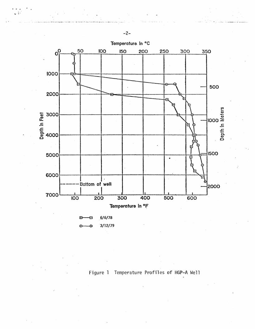
Prior to the well workover, the wellhead pressure during shut-in periods was
approximately 140 psig and the temperature profile inside the casing (see Fig. 1)
was low until it reached the 9-5/8" casing shoe at about 2200 ft below surface.
However, after the well flow test in November, 1978, the static wellhead pressure
began to increase gradually and by January 1979, the well had to be vented daily in
order to keep the pressure below 500 psig, and the temperature profile in the casing
showed a dramatic rise, especially in the section from 1450 ft to the bottom of the
9-5/8" casing shoe. Furthennore, a gas cap formed in the well-bore during static
condition, which was not observed prior to November 1978. These phenomena led to
the speculation that there was either a break in the casing which permitted hot
fluids to circulate inside of the well bore, or that the cement anchoring of the casing
to the fornlation had deteriorated, allowing well fluids to migrate upward on the
outside of the casing.
After consultation with Mr. Anthony Adduci, Mr. Martin Scheve and Dr. Bennie
DiBonna of the Department of Energy (DOE), a casing caliper log and a cement bond
log were run in May, 1979 to determine whether there was a break in the casing and/or
that the cement bond had deteriorated. No apparent break in the casing was detected,
however, substantial deterioration of the cemend bond was confinned, and the fact
that high temperature cement had not been used in the original cementing program
prompted the project to propose to U.S. DOE that a casing perforation and cement
squeeze job be performed to insure the integrity of the HGP-A Well. Subsequently,
DOE approved the proposal in June, 1969, and a geothermal well modification pennit
was issued by the State Department of Land and Natural Resources in September, 1979.
. - ".-." ' .. ~ .-..,..~ .----. ".- , - ~._. ~ ..-. ..: _..-.~. - .•..~ '. - .
-2-
Temperature In °c
500
II)LQ)-Q)
000 :::EoS.r::.-0.Q)
o
500
2000
350
600
300
500
250
400
200150
300
100
200
50
100
,...."'.
(.
~.
\I----
.:, \ --.......~
i\~~
~ -I
\~
'~f;l .I \.-1. ~ '\
\ ~,f-- ---- Bottom of well
~
I I ,, -I I I
2000
1000
5000
6000
7000
~ 3000If.5.c
!4000
Temperature In of
a---e f~/6/78
0----@3/12/79
Figure 1 Temperature Profiles of HGP-A Well
II. W0 R K0 V E R P LAN
Rogers Engineering Inc., of San Francisco was retained as the drilling con
sultant to the project and Mr. James Kuwada of Rogers was designated as the techni
cal consultant. Specifications for the workover were prepared by Rogers and invi
tations to bid were sent to potential drilling companies, in addition to general
advertising in June. Two bids were received in July and after evaluation of the
bids, Water Resources International, Inc. was selected. To further assist the
project, ~1r. Sheldon Hopkins of Global Geothermal was hired to serve as the drilling
supervisor to supervise the daily workover operations. Mr. Anthony Adduci of DOE/SAN
was the technical director for all technical decisions.
Several meetings were held among the drilling manager, the drilling supervisor
and the drilling contractor regarding tools, services and workover program in
August. The rig was moved to the site in early September and the workover program
commenced on September 15, 1979. This report describes the procedures followed
and equipment used in the completion of the workover.
Workover Plan... 'I'
In the contract with DOE, the project was directed to perform the following
tasks:
1. Acquire a workover rig to be placed at HGP-A with necessary blow-out
preventing devices.
2. Pressure test the casing for leakage.
3. Perforate, cement and restore cement bond.
3a. Cut off 7" liner at 3000 ft and remove.
4. Tie back 711 casing from 3000 ft to surface and cement to block off cool
water production zone between 2200-3000 ft and to anchor 7" tie back
string if deemed necessary.
5. Run cement bond logs to insure competency.
6. Cement the upper portion of the 7" slotted liner to tie down the liner and
to block off the cold water zone.
7. Perfonn mechanical caliper run inside the 7" slotted liner.
8. Ream out the inside of the slotted liner and obtain samples for analysis.
9. Remove or pound to the bottom of the hole the junk accumulated in the hole
and restore the hole to 6455 feet.
10. Obtain all permits, waivers, and inspections required by governmental
agencies having jurisdiction.
11. Report all efforts as part of the reporting requirements presently provided
on the original contract and the revisions thereto.
After several meetings among the project staff, the drilling manager and the
technical consultant, the following program was tentatively agreed upon subject to
change as the workover progressed.
1. Kill well by pumping in cold water.
2. Keeping well dead, rotate master valve to desired position to accommodate
set up of drilling rig, blow-out-preventer stack-mastergate, cross over
spool, double gate, Hydrill and rotating head.
3. Keeping well dead run temperature survey &caliper log (Otis).
-5-
4. Run in hole with 711 casing scraper & jars to 3200 ft.
5. Run and set HOWeO 711 23# EZSV #1 @ + 3150 ft.
6. Unsting from EZSV and spot spearhead of flow check fill at bottom of
slotted section.
7. Pullout of hole and pick up EZSV #2.
8. Run in hole and set @+ 2950 ft.
9. Pump spear head of IIFlochek-II II and cement as follows: Mix 20 ft3 1-1-1 IIG II
cement + 1 ft3 perlite + 1 ft3 sand + 0.5% CFR-2 + retarders as needed.
10. Pullout of hole with stinger and wait on cement.
11. Run in hole with stinger and stab into EZSV #2.
12. Pressure test with 1000 psig.
13. Resqueeze if necessary as many times as necessary.
14. After bridge is established, run in hole with 9-5/8 11 scraper. Then 9-5/8 11
RTTS and retrieve bridge plug combined or separately if necessary.
15. Set bridge plug at ~ 2100 ft.
16. Set RTTS at + 1000 ft. and test both sides. Isolate any leaks.
17. If no leaks are found run cement bond log on top 400 ft of hole, perfor-
ate and squeeze to surface is possible.
18. Clean out, cement, recover retrievable Bridge plug in top part of hole.
19. Decision may be made to cut 711 slotted liner and recover same, as follows:
20. Run in hole OE and change over to mud and loss circulation material.
21 •. Run in hole with casing cutter and cut casing below collar at + 2925 ft.
22. Run in hole with casing spear and jars and recover casing.
23. Underream 8-1/2 11 hal e to 1011.
24. Run in hole with 711 casing and casing bowl.
25. Cement to surface.
26. Install 1011 x 711 casing head and new master gate.
27. Run casing bond log.
-6-
28. If decision is made to cement existing slotted 711 liner proceed as
follows:
29. Set RTTS Packer (with 2 joints tailpipe) above each section of slotted
liner and cement. Wait on cement between jobs as needed.
30. Drill out cement and pressure test 711 liner above bridge plug.
31. If OK drill out EZSV Bridge Plugs and continue to top of junk and push
to bottom.
32. Flow well (supervised by University staff).
33. Rig down.
It is further agreed upon between the project and DOE that Mr. Anthony
Adduci shall be the technical director in DOE for all technical decisions.

','
III. W0 R K0 V E R SUM MAR Y
· ~. .Workover Summary
Approximately three weeks prior to the commencement of the workover, large
amounts of cold water at approximately 150 gpm were pumped into the HGP-A well to
kill the well pressure. Subsequently, about 80 gpm of cold water was pumped into
the well continuously to maintain the static water level in the well bore at approximately
400 ft. below ground level. The drilling rig and its supporting equipment were
mobilized and ready to go by September 15, 1979 with all necessary blowout pre
venting equipment installed.
Repeated pressure testing of the 9-5/8 11 casing with retrievable plug at
approximately 2000 ft. below rotary table (BRT) and RTTS tool at different depths
above the plug failed to reveal any significant leaks in the casing. A decision
was made then to set a cement plug at approximately 3000 ft. BRT to prevent well
fluids from producing into the well bore so that the casing perforation and cement
squeeze job can be performed. The top section of the original 711 liner was also
removed from 2161 to 2921 ft. BRT.
A HOWeO retrievable bridge plug was set at about 2000 ft BRT and a series of per
foration and cement squeeze job were performed at intervals 2150 to 2°152, 2110 to
2112, 1650 to 1652, 1250 to 1252 and 970 to 972 ft. BRT. (See Appendix D). It is
evident from the formation breakdown pressure that the cement outside of the casing
has deteriorated so that well flluids have migrated upward on the outside of the
casing. After the hole was cleaned to the HOWeO plug, the casing was pressure tested
for apparent leaks and no leaks were found.
Difficulty was experienced in retrieving the HOWeO plug at about 2200 ft. It
appeared that the 9-5/8 11 casing has come apart and gone out of alignment at about
2147 ft. BRT. After considerable amount of drilling, milling and rolling efforts,
the plug was retrieved.
A cement bond log was run to check on the effectiveness of the squeeze job. It
was discovered that all of the squeeze operations have improved the bonding substan
tially except at about 1650 ft. A decision was made to perforate and squeeze again at
..." .
-8-
1420 to 1422 ft. which was approximately half way between the two previous squeeze
operations at 1250 and 1650 ft BRT. This squeeze operation has improved the
bonding substantially between 1200 and 1500 ft. as evidenced from later cement
bond log.
A decision was made to tie back the 711 casing from the 711 liner stub at
2921 ft. BRT to the surface. 70 joints of 26-16 K55 buttress casing with stage-
cementing tools was run in and was stage-cemented to the surface and the rig was
shut down for the Discoverer's Day weekend to wait on cement.
After the break, cement bond logs were run to check the cementing job. It
was discovered that from 2500 to 2900 ft. the cement bond was not competent.
Squeeze jobs were then performed at 2963 to 2975 ft and at 2530 to 2533 ft. A
final cement bond log was run from surface to 2990 ft and over 80% bonding was shown
on almost the entire string.
A new wellhead was completed on the 711 casing and cement plug was drilled out,
cleaned out hole to 6430 ft. and drove junk to 6343 ft BRT. A banjo box was
installed and flow test equipment was attached to prepare for a brief flow test.
The well was flowed for 4-1/2 hours on October 17th and the production was approxi
mately the same as before the workover. The rig was subsequently released on
October 18, 1979.

IV.· 0 A I L Y 0 R ILL I NG REP 0 R T S

Sept. 15, 1979
Sept. 16, 1979
Sept. 17, 1979
Sept. 18, 1979
-9-
DAILY DRILLING REPORTS
Start rig time at 12:00 noon. Install blowout preventing
equipment (BOE) and Grant rotating head. Pressure test
BOE to 1000 ps i .
Scrape 7" liner to 3225 ft. below rotary table (BRT). Scrape
9-5/8" casing to top of liner at 2161 ft BRT. Tight spots
at 1996 - 2034 ft. and 2150 ft. BRT. Set 9-5/8" RTTS at
360 ft. BRT, pressurize between 360 ft. and surface to 1000
psi. Pressure declined 500 psi in 2 minutes. Pull RTTS out
of hole.
Set HOWCO retrievable bridge plug at 1958 ft BRT. Set RTTS
at 175 ft. BRT. Pressurize between RTTS and plug. Pressure
declined 500 psi in 3 minutes. Reset RTTS at 865 ft BRT.
Pressurize between RTTS and plug again to 1000 psi. Pressure
declined 350 psi in 15 minutes. Retrieve RTTS and run cement
bond log from 500 ft to 20 ft BRT. Retrieve HOWCO bridge
plug. Set]l' EZSV at 3140 ft BRT. Prepare for cementing.
With drill pipe at 3136 ft BRT. Inject 10 bbls of 10%
calcium chloride brine, 2 bbls water, 5 bbls"Flochek-II" and 2
bbls water. Follow immediately with 32 cu. ft. of API Class
G cement with 40% silica flour and 0.5% CFR-2. Displace cement
with 24 bb1s of water. Wait on cement (WOC) 13 hours. Run in
hole to tag cement. No cement. With drill pipe at 3136 ft BRT,
re-inject 10 bbls of calcium chloride brine, 1 bbl water, 5
bb1s of "F10chek-II" and 1 bbl w~ter. Follow immediately with 24
cu ft API class G cement with 40% silica flour and 0.5 %CFR-2.
Displace cement with 19 bbls of water. WOC 6-1/2 hrs. Run in
hole and tag top of cement at 3088 ft BRT at midnight.
· "'..
Sept. 19, 1979
Sept. 20, 1979
Sept. 21, 1979
Sept. 22, 1979
Sept. 23, 1979
-10-
With drill pipe above the top of cement plug, inject 10 bbls
water, follow by 32 cu ft of API class G cement with 40% silica
flour and 0.5% CFR-2 and displace with 17 bbls of water. WOC
2 hrs. Cut 7" slotted liner at 2921 ft. BRT. Spear liner at
2161 ft. BRT and recover and lay down 7/1 casing.
Scrape casing to 2190 BRT. Pick up 8-1/2 II bit to clean out
fill with mud to 2898 ft BRT. Circulate to clean out fill.
Set HOWCO retrievable bridge plug at 2196 ft BRT. Dump 10
sacks of sand on plug with drill pipe. Wait on sand 2-1/2 hrs.
Tag sand at 2179 ft BRT. Perforate casing from 2150 to 2152
ft BRT with 8 1/2 11 -ho1es. Set RTTS at 2165 ft BRT. Pressurize
to 1000 psi. No leaks. Set RTTS at 2075 ft BRT. Pump 20 cu ft
per minute water at 200 psi. Squeeze with 52 cu ft of API class
G cement with 40% si1i~a flour and 0.5% CFR-2. Displace cement
with 117 cuft of water. W.O.C.
W.O.C. till 10:00 am. Perforate casing at 2110 to 2112 ft SRT
with 8 l/2 11 -holes. Set RTTS at 2015 ft BRT. Pressurize to
1500 psi and obtain breakdown with 20 cu ftlmin water rate.
Squeeze with 178 cu ft of API class G cement with 40% silica
flour and 0.5% CFR-2. Displace with 21 bb1s of water. W.O.C.
6 hrs. Perforate cas i n9 from 1650 to 1652 ft BRT with 8 1/2/1
holes. Set RTTS at 1545 ft BRT. Obtain breakdown pressure at
200 psi with 20 ft3/m;n water rate. Squeeze with 162 cu ft of
API class G cement with 40% silica flour and 0.5% CFR-2. Dis
place with 22 cu ft water. W.O.C:
W.O.C. till 6:00 am. Perforate casing from 1250 to 1252 ft BRT
with 8 1/2-inch holes. Set RTTS at 1167 ft BRT. Breakdown
at 200 psi with 20 cu ftlmin water rate. Squeeze with 87 cu ft
Sept. 24, 1979
Sept. 25, 1979
Sept. 26, 1979
Sept. 27, 1979
Sept. 28. 1979
-11-
of API class G cement with 40% silica flour and 0.5% CFR-2.
Displace with 15 bbls of water. W.O.C. 6 hrs. Perforate casing
from 970 to 972 ft. BRT with 8 1/2"-holes. Set RTTS at 880 ft.
BRT. Breakdown at 2500 psi with 20 cu. ft./min. water rate. Squeeze
with 87 cu. ft. of API Class G cement with 40% silica flour and 0.5%
CFR-2 displaced with 11 bbls of water. W.O.C. till midnight.
W.O.C. till 5:00 am. With 8-1/2" bit drill out cement and
clean hole to 2147 ft. BRT. Bad spot in casing at 2147 ft. Trip
out of hole and change bit.
Drill on bad spot in casing at 2147 ft. BRT. Continue to drill
out cement and sand to 2186 ft. BRT. Pressure test 9-5/8" cas i ng.
Pressure declined 600 lb in 3 minutes. Trip out and return in
hole with retriever tool to retrieve HOWCO bridge plug. Succeed
in latching on the plug after three tries. Unsuccessful in
pulling through the casing bad spot at 2147 ft. BRT. Reset
bridge plug at 2172 ft. BRT. Return with 8-1/2" in casing
roller to work on the bad spot. Unable to pullout of hole.
Try to pull casing roller out. Stuck at 1794 ft. BRT. Run two
back-off shots at 1793 ft. BRT and backed off at 1793 ft. BRT.
Return in hole with drill collar, bumper sub and jars. Screw
into fish and retrieved the casing roller. Return in hole with
8-1/2" casing swedge to drive through bad spot to 2151 ft. BRT.
Pullout of hole and build tungston carbide face on bottom of
swedge.
With the rebui It swedge. mi 11 through bad spot in 9-5/8" cas i ng
at 2147 ft. BRT. Retrieve the HOWCD bridge plug after two tries.
With 8-1/2" cas i ng scraper. scrape to 2205 ft. BRT. Run cement
bond log.
Conti nue with cement bond log. Dri 11 out cement and fi 11 , con
dition hole and clean out to 3000 ft. BRT.
'.' .."Sept. 29» 1979
Sept. 30, 1979
Oct. " 1979
Oct. 2, 1979
Oct. 3, 1979
Oct. 4, 1979
Oct. 5, 1979
Attempt to run inside ]I' slotted liner stub at 2920 ft. BRT was
unsuccessful. Run in with 6" tapered mill and mill out top of
]I' to 2931 ft. BRT. Attempt to run inside 7" slotted liner stub
at 2920 ft. BRT was again unsuccessful. Run in with 6" tapered
mill and tagged fill at 2987 BRT.
Attempt to run inside ]U slotted liner with perforation gun failed.
Pick up ]U sizing tool and bumper sub to dress up ]I' liner. Tools
can not pass 2147 ft. BRT.
With hard facing 8-5/8 11 swedge and two 8-1/4" stubs, mill out bad
spots from 2145 to 2155 ft. BRT. Attempt to dress up 7" slotted
liner with ]I' dressing tool failed again. Set 9-5/8 11 retrievable
bridge plug at 1563 ft. BRT.
Place 10 cu ft of sand on plug. Perforate casing from 1420 to
1422 ft. BRT with 8 l/2-inch holes. Set RTTS at 1458 ft. BRT and
pressure test to 1000 ps1. Pull up and reset RTTS at 1260 ft. BRT
and pumped 20 cu ft of water per min. at 200 psi. Cemented with
162 cu ft of API class G cement with 40% silica flour, 0.5% CFR-2.
Displaced with 76 cu ft of water. W.O.C. 10 hours. Drill out
cement and retrieve bridge plug.
Millon ]I' slotted liner stub with 8-1/2 11 pilot mill to 2921 ft.
BRT. Clean out fill from 2990 to 3000 ft. BRT with 611 tapered
mill. With perforating gun and sinker bar shot 10 1/2-inch holes
from 2963 to 2975 ft. BRT. Set]l' RTTS at 2930 ft. BRT and break
down formation at 2000 psi.
Dress up 711 stub with dressing tool at 2921 ft. BRT. Change BOP
blind ram to 711• Run cement bond log inside 9-5/8 11 casing. Run
in 70 joints 26 16 K55 buttress casing with stage-cementing
tools (See AppenJix C).
Attempt to ci rcu1 ate at 711 stub fail ed. Dropped D. V. openi ng
plug and circulate at 2492 ft. BRT with 200 psi. Pumped 50 cu ft
Oct. 6, 1979
Oct. 7 &8
Oct. 9, 1979
Oct. 10, 1979
Oct. 11, 1979
Oct. 12, 1979
-13-
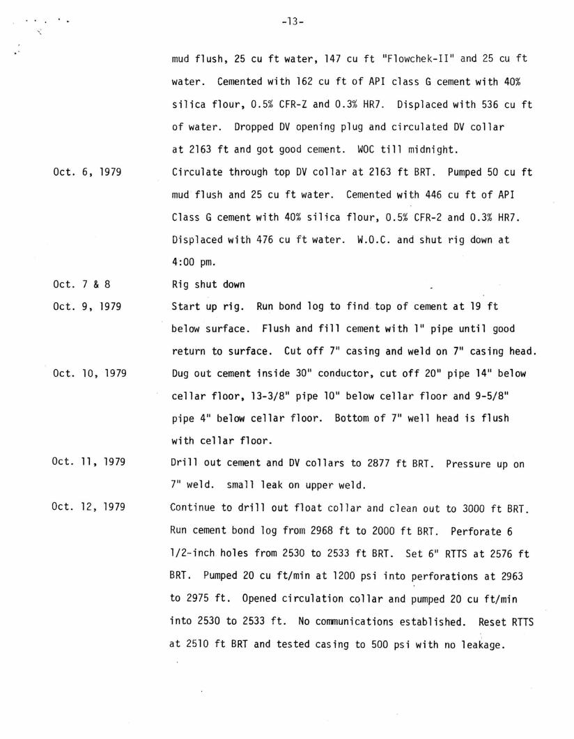
mud flush, 25 cu ft water, 147 cu ft IIFlowchek-II II and 25 cu ft
water. Cemented with 162 cu ft of API class G cement with 40%
silica flour, 0.5% CFR-Z and 0.3% HR7. Displaced with 536 cu ft
of water. Dropped DV opening plug and circulated DV collar
at 2163 ft and got good cement. WOC till midnight.
Circulate through top DV collar at 2163 ft BRT. Pumped 50 cu ft
mud flush and 25 cu ft water. Cemented with 446 cu ft of API
Class G cement with 40% silica flour, 0.5% CFR-2 and 0.3% HR7.
Displaced with 476 cu ft water. W.O.C. and shut rig down at
4:00 pm.
Rig shut down
Start up rig. Run bond log to find top of cement at 19 ft
below surface. Flush and fill cement with 111 pipe until good
return to surface. Cut off 711 cas i n9 and weld on 7" cas i n9 head.
Dug out cement inside 30 11 conductor, cut off 20 11 pipe 14 11 below
cellar floor, 13-3/811 pipe 1011 below cellar floor and 9-5/8 t1
pipe 411 below cellar floor. Bottom of 7" well head is flush
with cellar floor.
Drill out cement and DV collars to 2877 ft BRT. Pressure up on
711 weld. small leak on upper weld.
Continue to drill out float collar and clean out to 3000 ft BRT.
Run cement bond log from 2968 ft to 2000 ft BRT. Perforate 6
1/2··inch holes from 2530 to 2533 ft BRI. Set 611 RTTS at 2576 ft
BRT. Pumped 20 cu ft/min at 1200 psi into perforations at 2963
to 2975 ft. Opened circulation collar and pumped 20 cu ft/min
into 2530 to 2533 ft. No communications established. Reset RTTS
at 2510 ft SRT and tested casing to 500 psi with no leakage.

Oct. 13, 1979
Oct. 14, 1979
Oc t. 15, 1979
Oct. 16, 1979
Oct. 17, 1979
Oct. 18, 1979
-14-
Set 6" EZSV at 2573 ft. Pumped 20 cu ftjmin water into per
forations at 2963 to 2975 ft at 1200 psi. Cemented with 162 cu ft
of API class G cement with 40% silica flour, 0.5% CFR-2 and 0.3%
HR7. Displaced with 185 cu ft of water. Set RTTS at 2385 ft
and pumped 20 cu ft/min of water at 1500 psi in perforations at
2530 to 2533 ft BRT. Cemented with 81 cu ft of API Class G
cement with 40% silica flour, 0.5% CFR-2 and 0.3% HR7. Displaced
with 125 cu ft of water. W.O.C. Reweld 7" casing head and
X-rayed.
Drill out cement from 2348 ft to 2552 ft BRT. Test casing to
500 psi with no leakage. Drill out EZSV and cement from 2765 to
2993 ft BRT. Test casing to 500 psi with no leakage. Run cement
bond log on entire r casing.
Drill out cement and EZSV and clean out hole to 6340 ft BRT.
With 6" fl at bottom mi 11, mi 11 and dri ve junk to 6343 ft BRT.
Install banjo box and build flow test line to muffler. Run
Kuster temperature survey.
Bailout water till well flashed and flowed well for 4-1/2 hours.
Shut in and run Kuster temperature survey.
Lay down drill collars and drill pipes. Release rig at midnight.

V. CON C L U S ION
-15-
V. Conclusion
The HGP-A workover effort accomplished all of the objectives as
planned. It secured the cement bonding of the casing and prevented the
geothermal fluids from migrating up the annulus of the 9-5/8" casing.
Currently, after almost a year after the workover, the wellhead
pressure has stabilized to approximately 140 psig which was the same as
the shut-in pressure prior to November 1978. This further demonstrated
that the workover effort was successful.

· .. ,
VI. A C KNOW LED GEM E NT S
-16-
VI. Acknowledgements
The well workover is perforuled under the Department of Energy
Contract DE-AC03-78ET28420, and fundings from the State and County of
Hawaii and Hawaii Electric Light Company.
The Hawaii Natural Energy Institute and the Hawaii Institute of
Geophysics have also provided help in performing temperature survey,
well flashing and chemistry sampling.

A P PEN 0 I X A
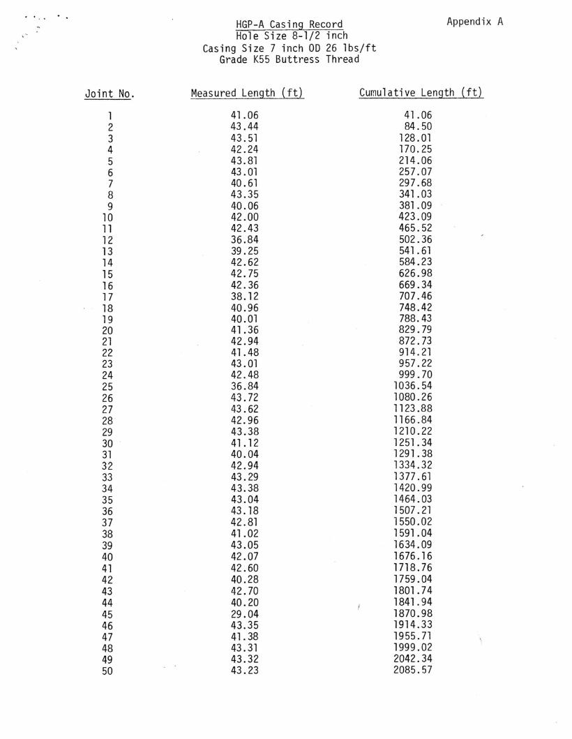
· .., HGP-A Casing Record Appendix A
Hole Size 8-1/2 inchCasing Size 7 inch 00 26 lbs/ft
Grade K55 Buttress Thread
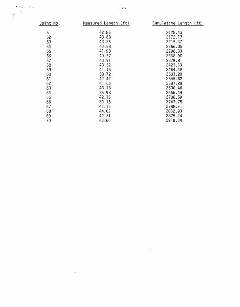
Joint No. Measured Length ( ft) Cumulative Length J.f!l
1 41.06 41.062 43.44 84.503 43.51 128.014 42.24 170.255 43.81 214.066 43.01 257.077 40.61 297.688 43.35 341.039 40.06 381.09
10 42.00 423.0911 42.43 465.5212 36.84 502.3613 39.25 541 .6114 42.62 584.2315 42.75 626.9816 42.36 669.3417 38.12 707.4618 40.96 748.4219 40.01 788.4320 41.36 829.7921 42.94 872.7322 41.48 914.2123 43.01 957.2224 42.48 999.7025 36.84 1036.5426 43.72 1080.2627 43.62 1123.8828 42.96 1166.8429 43.38 1210.2230 41.12 1251.3431 40.04 1291.3832 42.94 1334.3233 43.29 1377.6134 43.38 1420.9935 43.04 1464.0336 43.18 1507.2137 42.81 1550.0238 41.02 1591. 0439 43.05 1634.0940 42.07 1676.1641 42.60 1718.7642 40.28 1759.0443 42.70 1801.7444 40.20 1841.9445 29.04 1870.9846 43.35 1914.3347 41.38 1955.7148 43.31 1999.0249 43.32 2042.3450 43.23 2085.57
-IU-,.
Joint No. Measured Length ( ft) Cumulative Length (ft)
51 42.86 2128.4352 43.68 2172.1753 43.26 2215.3754 40.98 2256.3555 41.98 2298.3356 40.57 2338.9057 40.91 2379.8158 43.52 2423.3359 41. 15 2464.4860 38.72 2503.2061 42.42 2545.6262 41.66 2587.2863 43.18 2630.4664 35.98 2666.4465 42.15 2708.5966 39.16 2747.7567 41. 16 2788.9168 44.02 2832.9369 42.31 2875.2470 43.60 2918.84

A P PEN 0 I X B
-19
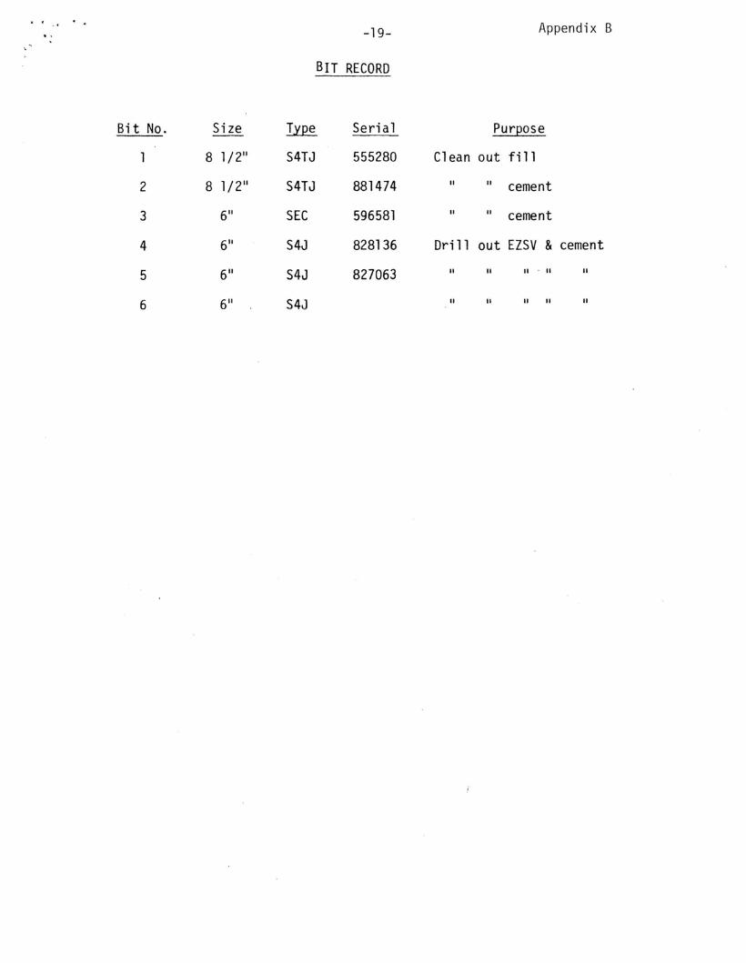
BIT RECORD
Appendix B
Bit No. Size ~ Seri a1 Purpose
8 1/2" S4TJ 555280 Clean out fi 11
2 8 1/2" S4TJ 881474 II II cement
3 6" SEC 596581 II II cement
4 6" S4J 828136 Drill out EZSV &cement
5 6" S4J 827063 II II II . II II
6 6" S4J II II " II II

A P PEN 0 I X C
-20-
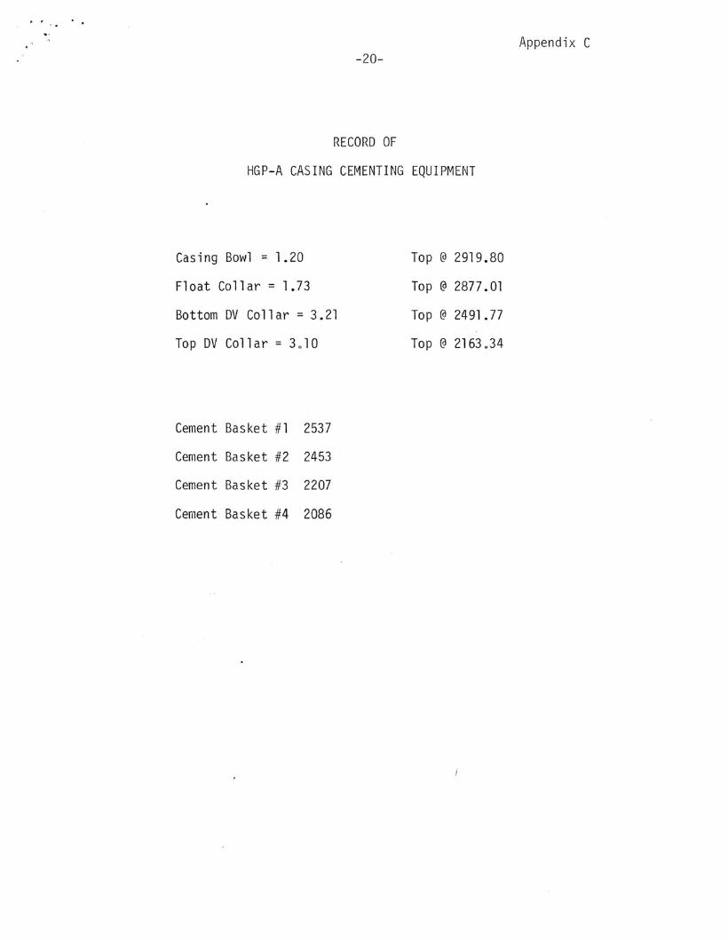
RECORD OF
HGP-A CASING CEMENTING EQUIPMENT
Appendix C
Casing Bowl = 1.20
Float Collar = 1.73
Bottom DV Collar = 3.21
Top DV Collar = 3010
Cement Basket #1 2537
Cement Basket #2 2453
Cement Basket #3 2207
Cement Basket #4 2086
Top @ 2919.80
Top @ 2877.01
Top @ 2491.77
Top @ 2163 034

A P PEN 0 I X 0
.. f' _"" ..
-21-
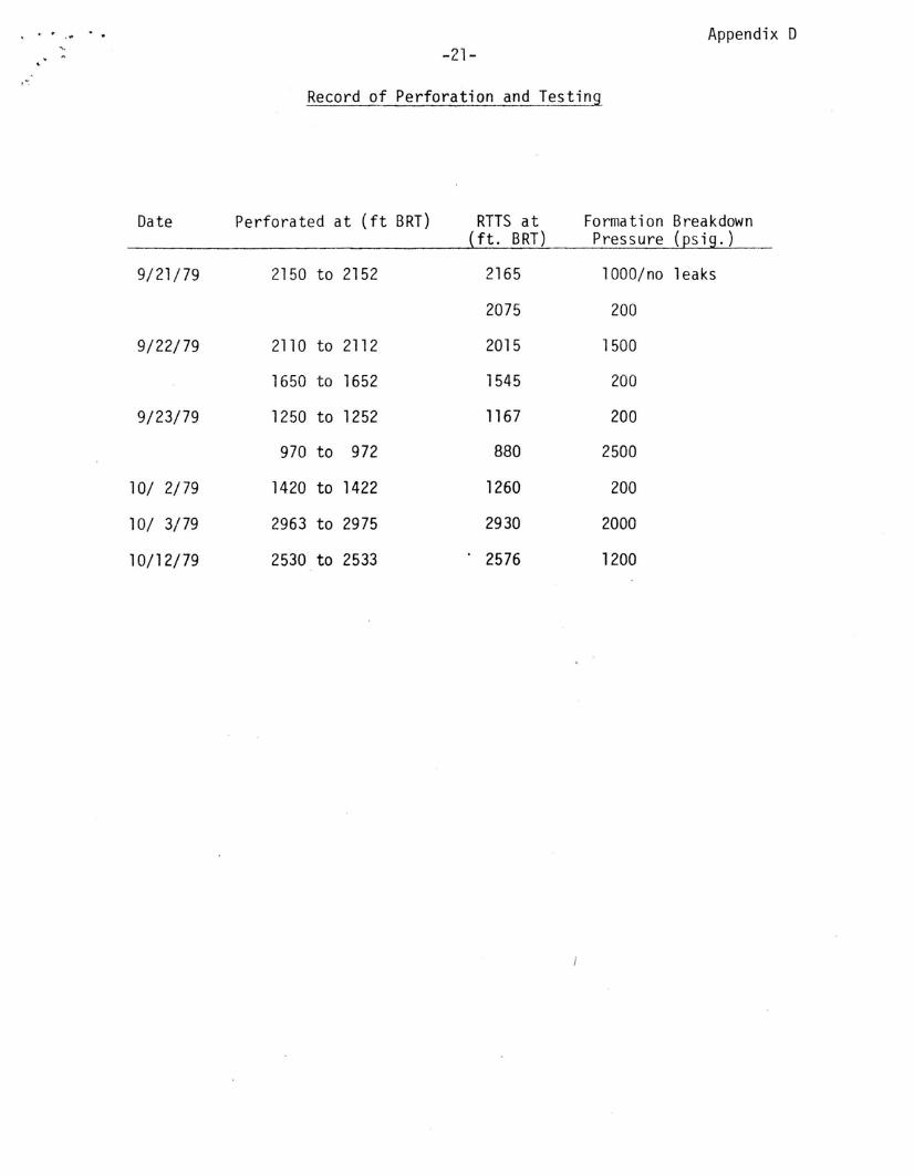
Record of Perforation and Testing
Appendix D
Date Perforated at (ft BRT) RTTS at Formation Breakdown(ft. BRT) Pressure (psig.)
9/21/79 2150 to 2152 2165 1000/no leaks
2075 200
9/22/79 2110 to 2112 2015 1500
1650 to 1652 1545 200
9/23/79 1250 to 1252 1167 200
970 to 972 880 2500
10/ 2/79 1420 to 1422 1260 200
10/ 3/79 2963 to 2975 2930 2000
10/12/79 2530 to 2533 2576 1200

A P PEN 0 I X E
-t..t..-
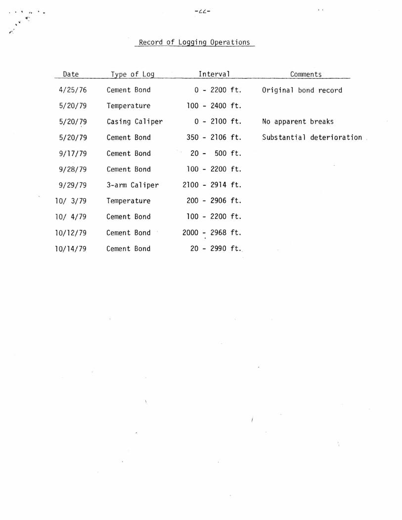
Record of Logging Operations
Date Type of Log Interva 1 Comments
4/25/76 Cement Bond 0 - 2200 ft. Original bond record
5/20/79 Temperature 100 - 2400 ft.
5/20/79 Casing Caliper o - 2100 ft. No apparent breaks
5/20/79 Cement Bond 350 - 2106 ft. Substantial deterioration.
9/17/79 Cement Bond 20 - 500 ft.
9/28/79 Cement Bond 100 - 2200 ft.
9/29/79 3-arm Caliper 2100 - 2914 ft.
10/ 3/79 Temperature 200 - 2906 ft.
10/ 4/79 Cement Bond 100 - 2200 ft.
10/12/79 Cement Bond 2000 - 2968 ft.
10/14/79 Cement Bond 20 - 2990 ft.
A P PEN D I X F
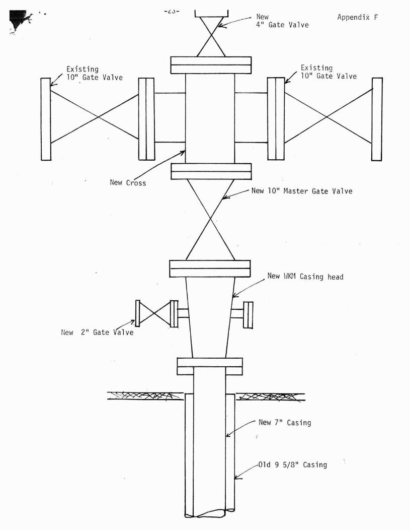
New 1011 ~1aster Gate Valve
Appendix F
Existing1011 Gate Valve
New \~Ki·1 Casing head
New4" Gate Valve
Existing1011 Gate Valve
New 211 Gate~
~.. "
" ..(' ~
~<
New 7" Casing
Old 9 5/8" Casing