Embed Size (px)
Citation preview
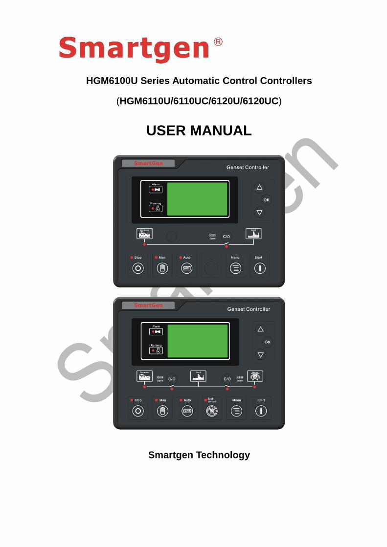
HGM6100U Series Automatic Control Controllers
(HGM6110U/6110UC/6120U/6120UC)
USER MANUAL
Smartgen Technology
Chinese trademark
English trademark
Smartgen — make your generator smart
Smartgen Technology Co., Ltd
No. 28 Jinsuo Road
Zhengzhou
Henan Province
P. R. China
Tel: +86-371-67988888
+86-371-67981888
+86-371-67991553
+86-371-67992951/67992952
+86-371-67981000(overseas)
Fax: 0086-371-67992952
Web: http://www.smartgen.com.cn
http://www.smartgen.cn
Email: [email protected]
All rights reserved. No part of this publication may be reproduced in any material form
(including photocopying or storing in any medium by electronic means or other) without
the written permission of the copyright holder.
Smartgen Technology reserves the right to change the contents of this document
without prior notice.
Software Version
Date Version Content
2011-09-15 1.0 Original release
2012-06-04 1.1 Some parameters are optimized.
HGM6100U Series Automatic Control Module
HGM6100U Automatic Genset Controller ISSUE 2012-06-04 Version 1.1 Page 3 of 32
Contents
1 SUMMARY ......................................................................................... 4
2 PERFORMANCE AND CHARACTERISTICS ..................................... 4
3 SPECIFICATION ................................................................................ 6
4 OPERATION ....................................................................................... 7
4.1 KEYS DSCRIPTION ......................................................................................... 7
4.2 CONTROLLER PANEL .................................................................................... 8
4.3 AUTOMATIC START/STOP OPERATION ........................................................ 8
4.4 MANUAL START/STOP OPERATION ............................................................ 10
5 PROTECTION .................................................................................. 10
5.1 WARNINGS .................................................................................................... 10
5.2 SHUTDOWN ALARMS ................................................................................... 12
6 CONNECTIONS ............................................................................... 13
7 PARAMETER RANGE AND DEFINITION ......................................... 15
7.1 PARAMETER CONTENT AND RANGE TABLE (TABLE 1) ............................ 15
7.2 PROGRAMMABLE OUTPUT 1-4 TABLE (TABLE 2) ..................................... 22
7.3 PROGRAMMABLE INPUT 1-5 TABLE (ALL IS ACTIVE WHEN CONNECT TO
GROUND (B-) (TABLE 3) ...................................................................................... 23
7.4 SENSOR SELECTION (TABLE 4) ................................................................. 24
7.5 CONDITIONS OF CRANK DISCONNECT (TABLE 5) ................................... 24
8 PARAMETER SETTING ................................................................... 25
9 SENSOR SETTING .......................................................................... 26
10 COMMISSIONING ............................................................................ 27
11 TYPICAL APPLICATION ................................................................ 29
12 INSTALLATION ................................................................................. 30
12.1 FIXING CLIPS ................................................................................................ 30
12.2 OVERALL DIMENSION AND PANEL CUTOUT ............................................. 31
13 FAULT FINDING ............................................................................... 32
HGM6100U Series Automatic Control Module
HGM6100U Automatic Genset Controller ISSUE 2012-06-04 Version 1.1 Page 4 of 32
1 SUMMARY
HGM6100U series automatic controller, integrating digital, intelligent and network
techniques, is used for automatic control and monitoring system of genset. It can carry
out functions of automatic start/stop, data measurement, alarm protection and three
“remote” (remote control, remote measure and remote communication). The controller
uses LCD display, optional display interface including Chinese, English, Spanish and
Russian with easy and reliable operation.
HGM6100U series automatic controller uses micro-processing technique which can
achieve precision measurement, value adjustment, timing and threshold setting etc..
All the parameters can be configured from front panel or use programmable interface
(or RS485 interface) to adjust via PC. It can be widely used in all types of automatic
control system for its compact structure, simple connections and high reliability.
2 PERFORMANCE AND CHARACTERISTICS
HGM6100U controller has four variants:
HGM6110U/6110UC: Automatic Start Module, it controls generator to start/stop by
remote start signal;
HGM6120U/6120UC: Based on HGM6110U/6110UC, it adds mains AC monitoring
and mains/generator automatic switching control (AMF), especially suitable for the
automation system composed by mains and genset.
Note1: HGM6110UC/6120UC has RS485 port, HGM6110U/6120U without.
Note2: HGM6110UC/6120UC is taken as an example to describe in this manual.
132*64 LCD display with backlight, optional language interface (Chinese, English,
Spanish and Russian), push-button operation;
Acrylic screen, improved wearable and scratch resistance property;
Silica-gel panel and keys can well adapt to higher and lower temperature;
With RS485 communication port, can achieve “three remote” functions via
MODBUS protocol;
Adapt to 3P4W, 3P3W, 1P2W and 2P3W (120V/240V), 50Hz/60Hz AC power
system;
Can measure and display 3 phase voltage, 3 phase current, frequency, power
parameter of mains/gens;
HGM6100U Series Automatic Control Module
HGM6100U Automatic Genset Controller ISSUE 2012-06-04 Version 1.1 Page 5 of 32
Mains Generator
Line voltage (Uab, Ubc, and Uca) Line voltage (Uab, Ubc, and Uca)
Phase voltage (Ua, Ub, and Uc) Phase voltage (Ua, Ub, and Uc)
Frequency HZ Frequency HZ
Load
Current IA, IB, IC
Active power KW
Reactive power KVar
Apparent power KVA
Power factor PF
Generator accumulated energy kWh
Mains have functions of over/under voltage and lack of phase; Gens have functions
of over/under voltage, over/under frequency and over current;
Precision measure and display of parameters about engine,
Temp. (WT), °C/ °F both are displayed
Oil pressure (OP), kPa/Psi/Bar are all displayed
Fuel level (FL), %
Speed (SPD), RPM
Battery Voltage (VB), V
Charger Voltage (VD), V
Hours counter (HC) can accumulate Max. 999999 hours.
Start times can accumulate Max.999999 times.
Control protection: Automatic start/stop of genset, load transfer(ATS control) and
perfect failure display and protection;
With ETS, idle speed control, pre-heat control, speed droop/raising control, all of
them are relay output;
Parameter setting: Allow user to modify setting and store them in internal FLASH
memory. The parameters cannot be lost even when power off. All of parameters can
be set not only from the front panel, but also use programmable interface (or PS485
interface) to adjust them via PC.;
Multi sensors of temperature, pressure and fuel level can be used directly,
parameters can be defined by user;
Multi conditions of crank disconnect (speed sensor, oil pressure, generator) can be
selected;
Power supply range: (8~35)VDC, accommodating to different starting battery volts;
HGM6100U Series Automatic Control Module
HGM6100U Automatic Genset Controller ISSUE 2012-06-04 Version 1.1 Page 6 of 32
All parameters use digital modulation, instead of analog modulation using
conventional potentiometer, having improved reliability and stability;
Add rubber gasket between shell and controller screen, the waterproof can reach
IP55;
Controller is fixed by metal fixing clips;
Modular design, flame-retardant ABS shell, embedded mounting, compact structure
and easy installation.
3 SPECIFICATION
Items Contents
Working Voltage DC8.0V to DC35.0V, continuous
Power Consumption <3W(Standby mode: ≤2W)
AC Voltage Input Range
3P4W
3P3W
1P2W
2P3W
15V AC - 360 V AC (ph-N)
30V AC - 620 V AC (ph-ph)
15V AC - 360 V AC (ph-N)
15V AC - 360 V AC (ph-N)
AC Alternator Frequency 50Hz/60Hz
Rotate speed sensor Voltage 1.0V to 24V (RMS)
Rotate speed sensor Frequency 10,000 Hz (max.)
Start Relay Output 16 Amp DC28V at supply voltage
Fuel Relay Output 16 Amp DC28V at supply voltage
Programmable Relay Output 1 7 Amp DC28V at supply voltage
Programmable Relay Output 2 7 Amp 250VAC volt-free output
Programmable Relay Output 3 16 Amp 250VAC volt-free output
Programmable Relay Output 4 16 Amp 250VAC volt-free output
Overall Dimensions 197 mm x 152 mm x 47mm
Panel Cutout 186mm x 141mm
C.T. Secondary Current 5A (rated)
Working Condition Temperature: (-25~70)ºC; Humidity: (20~90)%
Storage Condition Temperature: (-30~+80)ºC
Protection Level
IP55: when waterproof rubber gasket added
between controller and its panel.
IP42: when waterproof rubber gasket not added
HGM6100U Series Automatic Control Module
HGM6100U Automatic Genset Controller ISSUE 2012-06-04 Version 1.1 Page 7 of 32
between controller and its panel.
Insulation Intensity
Object: among in input/output/power
Quote standard: IEC688-1992
Test way: AC1.5 kV / 1min 3mA leakage current
Weight 0.56kg
4 OPERATION
4.1 KEYS DSCRIPTION
Stop/ Reset
Can stop generator under Manual/Auto mode; Can reset
shutdown alarm; Press this key at least 3 seconds to test
panel indicators are OK or not(lamp test);
During stopping process, press this key again can stop
generator immediately.
Start Start genset under Manual or Manual Test mode.
Manual Pressing this key will set the module as Manual mode.
Auto Pressing this key will set the module as Auto mode.
Running with load
Controller is under manual testing mode.
Under this mode, gen-set will run automatically with load
when gens normal. (HGM6110UC without)
Gens Close/Open Can control gens to switch on or off in Manual mode.
Set/ Confirm Shift cursor to confirm In parameters setting menu.
Up/Increase
Screen scroll;
Up cursor and increase value in setting menu.
Down/Decrease
Scroll screen;
Down cursor and decrease value in setting menu.
Menu
Pressing this key will set menu;
Again pressing this key can return main interface.
HGM6100U Series Automatic Control Module
HGM6100U Automatic Genset Controller ISSUE 2012-06-04 Version 1.1 Page 8 of 32
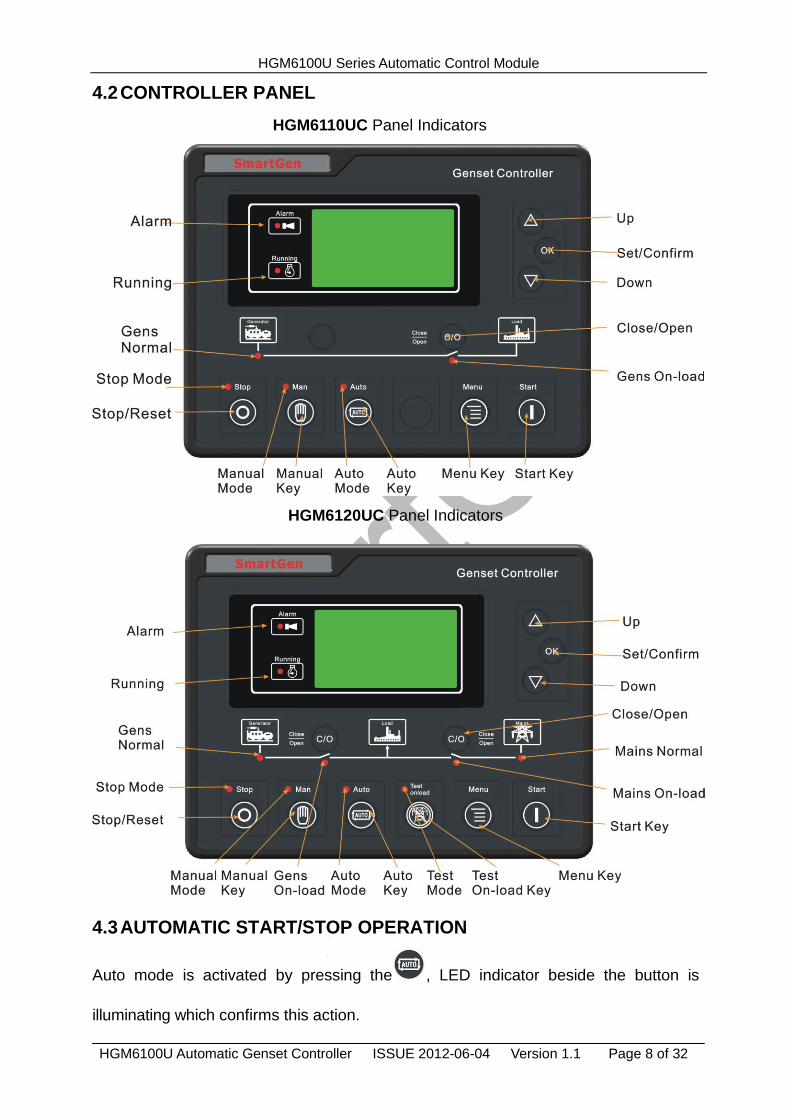
4.2 CONTROLLER PANEL
HGM6110UC Panel Indicators
HGM6120UC Panel Indicators
4.3 AUTOMATIC START/STOP OPERATION
Auto mode is activated by pressing the , LED indicator beside the button is
illuminating which confirms this action.
HGM6100U Series Automatic Control Module
HGM6100U Automatic Genset Controller ISSUE 2012-06-04 Version 1.1 Page 9 of 32
Starting Sequence,
1) HGM6120UC: When mains is abnormal (over/under voltage, lack of phase), enter
into “Mains Abnormal Delay” and LCD displays count-down time. When delay is over,
“Start Delay” begins.
2) HGM6110UC: when “remote start” input is active, enter into “Start Delay”.
3) “Count- down” of start delay is displayed in LCD.
4) When start delay is over, preheat relay is outputting (if configured), “Preheat Delay
XX s” is displayed in LCD.
5) When preheat delay is over, fuel relay is outputting for 1s and then start relay outputs;
if genset failed to start during “Crank Time”, the fuel and start relay stop outputting
and enter into “Crank Rest Time” and wait for next cranking.
6) If genset failed to start within set start times, the fourth line of LED will turn black and
Fail to Start alarm will be displayed.
7) Any time to start genset successfully, it will enter into “Safe Running”. During this
period, alarms of low oil pressure, high temperature, under speed, charge failure and
Aux. input (be configured) are disabled. As soon as this delay is over, genset will
enter into “Start Idle Delay” (if configured).
8) During start idle delay, alarms of under speed, under frequency, under voltage are
disabled. As soon as this delay is over, genset will enter into “Warming up Delay” (if
configured).
9) When “Warming up Delay” is over, the indicator is illuminating if gens normal. If
voltage and frequency of engine reach the load requirement, close relay outputs,
genset is taking load and indicator illuminates; if engine voltage or frequency is
abnormal, controller will alarm and shutdown (LCD displays the alarm information).
Stopping Sequence,
1) HGM6120UC: during normal running, if mains normal, genset will enter into “Mains
Normal Delay”, when mains indicator illuminates, “Stop Delay” begins.
2) HGM6110UC: genset enters into “Stop Delay” as soon as “Remote Start” is inactive.
3) When “Stop Delay” is over, genset enters into “Cooling Delay”. Closing relay is
disconnected. After switch “Transfer Rest Delay”, closing relay is outputting, mains is
taking load, generator indicator eliminates while mains indicator illuminates.
4) When entering “Stop Idle Delay”, idle relay is energized to output. (If configured).
HGM6100U Series Automatic Control Module
HGM6100U Automatic Genset Controller ISSUE 2012-06-04 Version 1.1 Page 10 of 32
5) When entering “ETS Delay”, ETS relay is energized to output, fuel relay output is
disconnected.
6) When entering “Genset at Rest”, genset will automatically judge if it has stopped.
7) When genset has stopped, enter into standby mode; if genset failed to stop,
controller will alarm (“Fail to Stop” alarm will be displayed in LCD).
4.4 MANUAL START/STOP OPERATION
1) HGM6120UC, Auto Mode is active when press and its indicator illuminates.
Press , then controller enters into “Manual Test Mode” and its indicator is
illuminating. Under both of the modes, press to start genset, it can automatically
detect crank disconnect and accelerate to high speed running. If there is high
temperature, low oil pressure, over speed and abnormal voltage during genset
running, controller can protect genset to stop (detail procedures please refer to
No.4~9 of Auto start operation). Under Manual Mode, switch won’t transfer
automatically, it is necessary to press to transfer load. Under “Manual Test Mode”,
after genset runs well in high speed, no matter mains is normal or not, loading switch
will be transferred to gens.
2) HGM6110UC, Auto Mode is active when pressing , and its indicator is
illuminating. Then press to start genset, it can automatically detect crank
disconnect and accelerate to high speed running. If there is high temperature, low oil
pressure, over speed and abnormal voltage during running, controller can protect
genset to stop quickly (detail procedures please refer to No.4~9 of Auto start
operation). After genset runs well in high speed, press and gens take load.
3) Manual stop, pressing can shut down the running genset (detail procedures
please refer to No.3~7 of Auto stop operation).
5 PROTECTION
5.1 WARNINGS
When controller detects the warning signal, the genset only alarm and not stop. The
HGM6100U Series Automatic Control Module
HGM6100U Automatic Genset Controller ISSUE 2012-06-04 Version 1.1 Page 11 of 32
alarms are displayed in LCD.
Warnings as following,
No. Items Description
1 Loss Of Speed
Signal
When the speed of genset is 0 and speed loss delay is 0,
controller will send warning alarm signal and it will be
displayed in LCD.
2 Genset Over
Current
When the current of genset is higher than threshold and
setting over current delay is 0, controller will send warning
alarm signal and it will be displayed in LCD.
3 Fail To Stop
When genset cannot stop after the “stop delay” is over,
controller will send warning alarm signal and it will be
displayed in LCD.
4 Low Fuel Level
When the fuel level of genset is lower than threshold or low
fuel level warning is active, controller will send warning
alarm signal and it will be displayed in LCD.
5 Charge Failure
When the voltage of genset charger is lower than threshold,
controller will send warning alarm signal and it will be
displayed in LCD.
6 Battery Under
Voltage
When the battery voltage of genset is lower than threshold,
controller will send warning alarm signal and it will be
displayed in LCD.
7 Battery Over
Voltage
When the battery voltage of genset is higher than threshold,
controller will send warning alarm signal and it will be
displayed in LCD.
8 Low Water Level When low water level input is active, controller will send
warning alarm signal and it will be displayed in LCD.
9 Temp. Sensor
Open Circuit
When sensor hasn’t connected to corresponding port,
controller will send warning alarm signal and it will be
displayed in LCD.
10
Oil Pressure
Sensor Open
Circuit
When sensor hasn’t connected to corresponding port,
controller will send warning alarm signal and it will be
displayed in LCD.
11 Maintenance time
out warn
When genset running time is longer than maintenance time
of user setting, and the maintenance action is set as
warning, controller send warning alarm signal and it will be
displayed in LCD. When maintenance action type is set as
“Not used”, maintenance alarm reset.
HGM6100U Series Automatic Control Module
HGM6100U Automatic Genset Controller ISSUE 2012-06-04 Version 1.1 Page 12 of 32
5.2 SHUTDOWN ALARMS
When controller detects shutdown alarm, it will send signal to open switch and stop
genset. The alarms are displayed in LCD.
Shutdown alarms as following,
No. Items Description
1 Emergency Stop When controller detects emergency stop signal, it will send
a stop alarm signal and it will be displayed in LCD.
2 High Temp.
Shutdown
When the temperature of water/cylinder is higher than set
threshold, controller will send a stop alarm signal and it will
be displayed in LCD.
3 Low Oil Pressure
Shutdown
When oil pressure is lower than threshold, controller will
send a stop alarm signal and it will be displayed in LCD.
4 Over Speed
Shutdown
When genset speed is higher than set threshold, controller
will send a stop alarm signal and it will be displayed in LCD.
5 Under Speed
Shutdown
When genset speed is lower than set threshold, controller
will send a stop alarm signal and it will be displayed in LCD.
6 Loss Of Speed
Signal Shutdown
When rotate speed is 0 and delay is not 0, controller will
send a stop alarm signal and it will be displayed in LCD.
7
Genset Over
Voltage
Shutdown
When genset voltage is higher than threshold, controller will
send a stop alarm signal and it will be displayed in LCD.
8
Genset Under
Voltage
Shutdown
When genset voltage is under set threshold, controller will
send a stop alarm signal and it will be displayed in LCD.
9
Genset Over
Current
Shutdown
When genset current is higher than set threshold and delay
is not 0, it will send a stop alarm signal and it will be
displayed in LCD.
10 Fail To Start Within set start times, if failed to start, controller will send a
stop alarm signal and it will be displayed in LCD.
11 Over Frequency
Shutdown
When genset frequency is higher than set threshold,
controller will send a stop alarm signal and it will be
displayed in LCD.
12 Under Frequency
Shutdown
When genset frequency is lower than set threshold,
controller will send a stop alarm signal and it will be
displayed in LCD.
13 Genset Failed When genset frequency is 0, controller will send a stop
alarm signal and it will be displayed in LCD.
14 Low Fuel Level When fuel level low input is active, controller will send a
stop alarm signal and it will be displayed in LCD.
15 Low Water Level When genset water level low input is active, controller will
send a stop alarm signal and it will be displayed in LCD.
HGM6100U Series Automatic Control Module
HGM6100U Automatic Genset Controller ISSUE 2012-06-04 Version 1.1 Page 13 of 32
No. Items Description
16 Temp. Sensor
Open Circuit
When sensor hasn’t connected to corresponding port,
controller will send shutdown alarm signal and it will be
displayed in LCD.
17
Oil Pressure
Sensor Open
Circuit
When sensor hasn’t connected to corresponding port,
controller will send shutdown alarm signal and it will be
displayed in LCD.
18 Maintenance time
out shutdown
When genset running is longer than maintenance time of
user setting, and maintenance action is set as shutdown,
controller send shutdown alarm signal and it will be
displayed in LCD. When maintenance action type is set as
“Not used”, maintenance alarm reset.
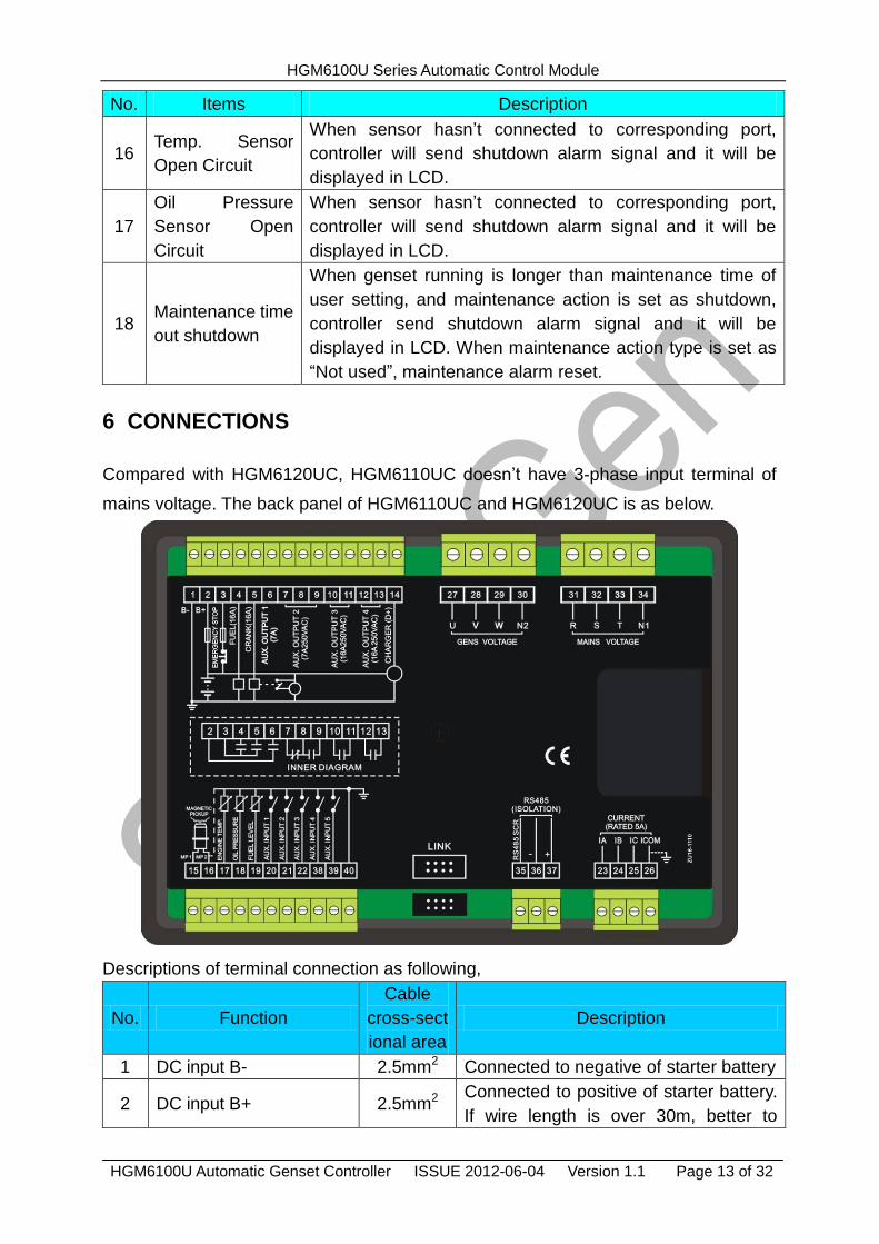
6 CONNECTIONS
Compared with HGM6120UC, HGM6110UC doesn’t have 3-phase input terminal of
mains voltage. The back panel of HGM6110UC and HGM6120UC is as below.
Descriptions of terminal connection as following,
No. Function
Cable
cross-sect
ional area
Description
1 DC input B- 2.5mm2 Connected to negative of starter battery
2 DC input B+ 2.5mm2 Connected to positive of starter battery.
If wire length is over 30m, better to
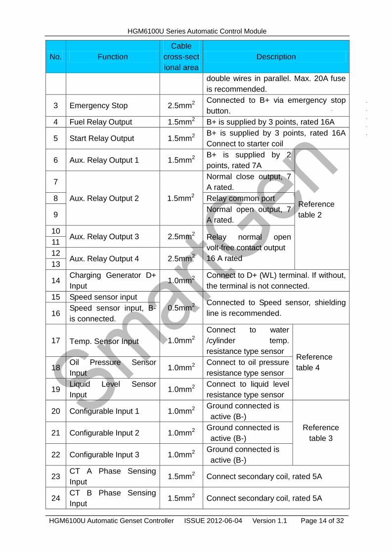
HGM6100U Series Automatic Control Module
HGM6100U Automatic Genset Controller ISSUE 2012-06-04 Version 1.1 Page 14 of 32
No. Function
Cable
cross-sect
ional area
Description
double wires in parallel. Max. 20A fuse
is recommended.
3 Emergency Stop 2.5mm2 Connected to B+ via emergency stop
button.
4 Fuel Relay Output 1.5mm2 B+ is supplied by 3 points, rated 16A
5 Start Relay Output 1.5mm2 B+ is supplied by 3 points, rated 16A
Connect to starter coil
6 Aux. Relay Output 1 1.5mm2 B+ is supplied by 2
points, rated 7A
Reference
table 2
7
Aux. Relay Output 2 1.5mm2
Normal close output, 7
A rated.
8 Relay common port
9 Normal open output, 7
A rated.
10 Aux. Relay Output 3 2.5mm2 Relay normal open
volt-free contact output
16 A rated
11
12 Aux. Relay Output 4 2.5mm2
13
14 Charging Generator D+
Input 1.0mm2
Connect to D+ (WL) terminal. If without,
the terminal is not connected.
15 Speed sensor input
0.5mm2 Connected to Speed sensor, shielding
line is recommended. 16 Speed sensor input, B-
is connected.
17 Temp. Sensor Input 1.0mm2
Connect to water
/cylinder temp.
resistance type sensor Reference
table 4 18 Oil Pressure Sensor
Input 1.0mm2
Connect to oil pressure
resistance type sensor
19 Liquid Level Sensor
Input 1.0mm2
Connect to liquid level
resistance type sensor
20 Configurable Input 1 1.0mm2 Ground connected is
active (B-)
Reference
table 3 21 Configurable Input 2 1.0mm2
Ground connected is
active (B-)
22 Configurable Input 3 1.0mm2 Ground connected is
active (B-)
23 CT A Phase Sensing
Input 1.5mm2 Connect secondary coil, rated 5A
24 CT B Phase Sensing
Input 1.5mm2 Connect secondary coil, rated 5A
HGM6100U Series Automatic Control Module
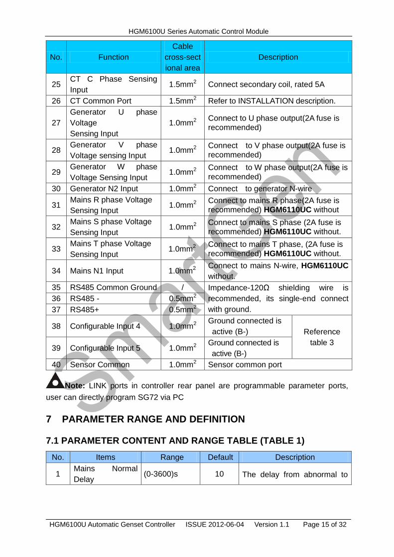
HGM6100U Automatic Genset Controller ISSUE 2012-06-04 Version 1.1 Page 15 of 32
No. Function
Cable
cross-sect
ional area
Description
25 CT C Phase Sensing
Input 1.5mm2 Connect secondary coil, rated 5A
26 CT Common Port 1.5mm2 Refer to INSTALLATION description.
27
Generator U phase
Voltage
Sensing Input
1.0mm2 Connect to U phase output(2A fuse is recommended)
28 Generator V phase
Voltage sensing Input 1.0mm2
Connect to V phase output(2A fuse is recommended)
29 Generator W phase
Voltage Sensing Input 1.0mm2
Connect to W phase output(2A fuse is
recommended)
30 Generator N2 Input 1.0mm2 Connect to generator N-wire
31 Mains R phase Voltage
Sensing Input 1.0mm2
Connect to mains R phase(2A fuse is recommended) HGM6110UC without
32 Mains S phase Voltage
Sensing Input 1.0mm2
Connect to mains S phase (2A fuse is recommended) HGM6110UC without.
33 Mains T phase Voltage
Sensing Input 1.0mm2
Connect to mains T phase, (2A fuse is recommended) HGM6110UC without.
34 Mains N1 Input 1.0mm2 Connect to mains N-wire, HGM6110UC
without.
35 RS485 Common Ground / Impedance-120Ω shielding wire is
recommended, its single-end connect
with ground.
36 RS485 - 0.5mm2
37 RS485+ 0.5mm2
38 Configurable Input 4 1.0mm2 Ground connected is
active (B-) Reference
table 3 39 Configurable Input 5 1.0mm2
Ground connected is
active (B-)
40 Sensor Common 1.0mm2 Sensor common port
Note: LINK ports in controller rear panel are programmable parameter ports,
user can directly program SG72 via PC
7 PARAMETER RANGE AND DEFINITION
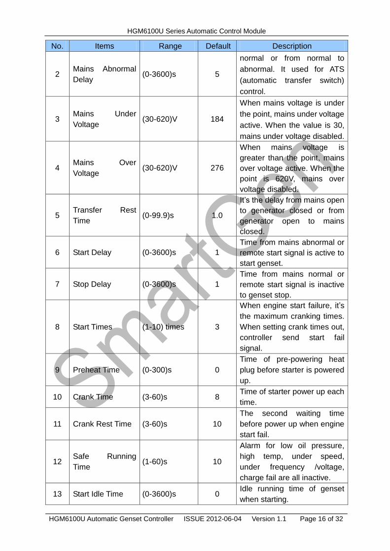
7.1 PARAMETER CONTENT AND RANGE TABLE (TABLE 1)
No. Items Range Default Description
1 Mains Normal
Delay (0-3600)s 10 The delay from abnormal to
HGM6100U Series Automatic Control Module
HGM6100U Automatic Genset Controller ISSUE 2012-06-04 Version 1.1 Page 16 of 32
No. Items Range Default Description
2 Mains Abnormal
Delay (0-3600)s 5
normal or from normal to
abnormal. It used for ATS
(automatic transfer switch)
control.
3 Mains Under
Voltage (30-620)V 184
When mains voltage is under
the point, mains under voltage
active. When the value is 30,
mains under voltage disabled.
4 Mains Over
Voltage (30-620)V 276
When mains voltage is
greater than the point, mains
over voltage active. When the
point is 620V, mains over
voltage disabled.
5 Transfer Rest
Time (0-99.9)s 1.0
It’s the delay from mains open
to generator closed or from
generator open to mains
closed.
6 Start Delay (0-3600)s 1
Time from mains abnormal or
remote start signal is active to
start genset.
7 Stop Delay (0-3600)s 1
Time from mains normal or
remote start signal is inactive
to genset stop.
8 Start Times (1-10) times 3
When engine start failure, it’s
the maximum cranking times.
When setting crank times out,
controller send start fail
signal.
9 Preheat Time (0-300)s 0
Time of pre-powering heat
plug before starter is powered
up.
10 Crank Time (3-60)s 8 Time of starter power up each
time.
11 Crank Rest Time (3-60)s 10
The second waiting time
before power up when engine
start fail.
12 Safe Running
Time (1-60)s 10
Alarm for low oil pressure,
high temp, under speed,
under frequency /voltage,
charge fail are all inactive.
13 Start Idle Time (0-3600)s 0 Idle running time of genset
when starting.
HGM6100U Series Automatic Control Module
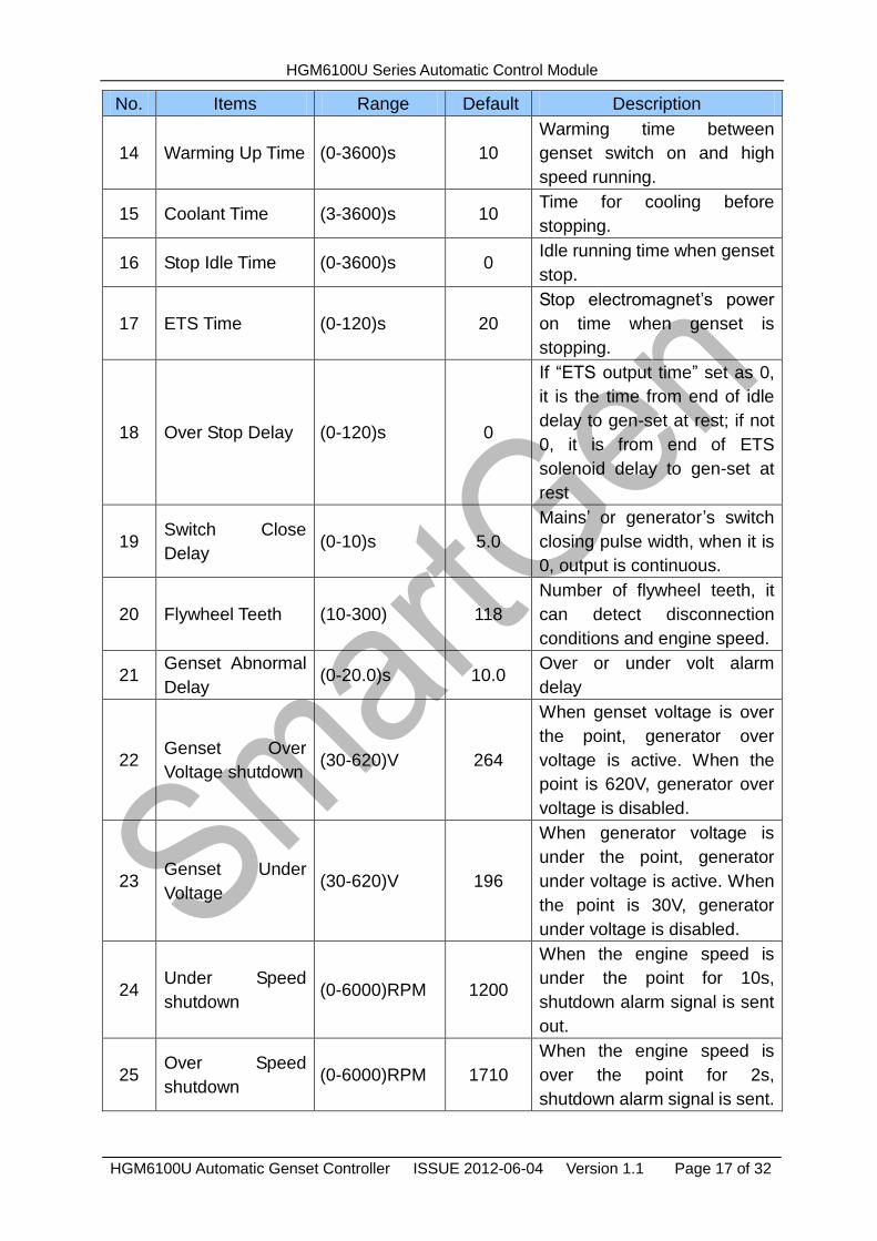
HGM6100U Automatic Genset Controller ISSUE 2012-06-04 Version 1.1 Page 17 of 32
No. Items Range Default Description
14 Warming Up Time (0-3600)s 10
Warming time between
genset switch on and high
speed running.
15 Coolant Time (3-3600)s 10 Time for cooling before
stopping.
16 Stop Idle Time (0-3600)s 0 Idle running time when genset
stop.
17 ETS Time (0-120)s 20
Stop electromagnet’s power
on time when genset is
stopping.
18 Over Stop Delay (0-120)s 0
If “ETS output time” set as 0,
it is the time from end of idle
delay to gen-set at rest; if not
0, it is from end of ETS
solenoid delay to gen-set at
rest
19 Switch Close
Delay (0-10)s 5.0
Mains’ or generator’s switch
closing pulse width, when it is
0, output is continuous.
20 Flywheel Teeth (10-300) 118
Number of flywheel teeth, it
can detect disconnection
conditions and engine speed.
21 Genset Abnormal
Delay (0-20.0)s 10.0
Over or under volt alarm
delay
22 Genset Over
Voltage shutdown (30-620)V 264
When genset voltage is over
the point, generator over
voltage is active. When the
point is 620V, generator over
voltage is disabled.
23 Genset Under
Voltage (30-620)V 196
When generator voltage is
under the point, generator
under voltage is active. When
the point is 30V, generator
under voltage is disabled.
24 Under Speed
shutdown (0-6000)RPM 1200
When the engine speed is
under the point for 10s,
shutdown alarm signal is sent
out.
25 Over Speed
shutdown (0-6000)RPM 1710
When the engine speed is
over the point for 2s,
shutdown alarm signal is sent.
HGM6100U Series Automatic Control Module
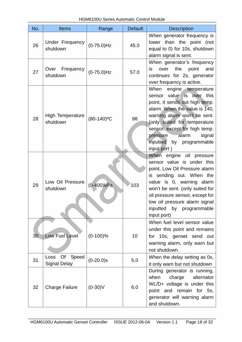
HGM6100U Automatic Genset Controller ISSUE 2012-06-04 Version 1.1 Page 18 of 32
No. Items Range Default Description
26 Under Frequency
shutdown (0-75.0)Hz 45.0
When generator frequency is
lower than the point (not
equal to 0) for 10s, shutdown
alarm signal is sent.
27 Over Frequency
shutdown (0-75.0)Hz 57.0
When generator’s frequency
is over the point and
continues for 2s, generator
over frequency is active.
28 High Temperature
shutdown (80-140)ºC 98
When engine temperature
sensor value is over this
point, it sends out high temp.
alarm. When the value is 140,
warning alarm won’t be sent.
(only suited for temperature
sensor, except for high temp.
pressure alarm signal
inputted by programmable
input port )
29 Low Oil Pressure
shutdown (0-400)kPa 103
When engine oil pressure
sensor value is under this
point, Low Oil Pressure alarm
is sending out. When the
value is 0, warning alarm
won’t be sent. (only suited for
oil pressure sensor, except for
low oil pressure alarm signal
inputted by programmable
input port)
30 Low Fuel Level (0-100)% 10
When fuel level sensor value
under this point and remains
for 10s, genset send out
warning alarm, only warn but
not shutdown.
31 Loss Of Speed
Signal Delay (0-20.0)s 5.0
When the delay setting as 0s,
it only warn but not shutdown
32 Charge Failure (0-30)V 6.0
During generator is running,
when charge alternator
WL/D+ voltage is under this
point and remain for 5s,
generator will warning alarm
and shutdown.
HGM6100U Series Automatic Control Module
HGM6100U Automatic Genset Controller ISSUE 2012-06-04 Version 1.1 Page 19 of 32
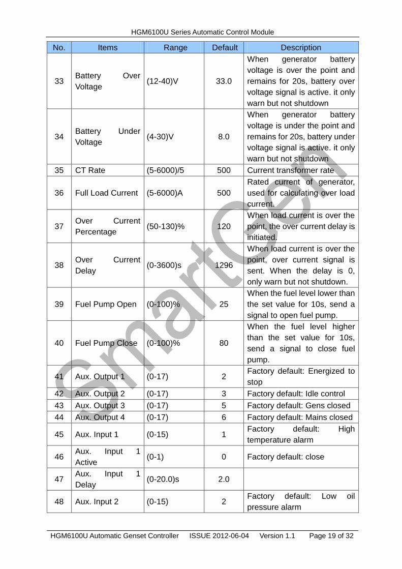
No. Items Range Default Description
33 Battery Over
Voltage (12-40)V 33.0
When generator battery
voltage is over the point and
remains for 20s, battery over
voltage signal is active. it only
warn but not shutdown
34 Battery Under
Voltage (4-30)V 8.0
When generator battery
voltage is under the point and
remains for 20s, battery under
voltage signal is active. it only
warn but not shutdown
35 CT Rate (5-6000)/5 500 Current transformer rate
36 Full Load Current (5-6000)A 500
Rated current of generator,
used for calculating over load
current.
37 Over Current
Percentage (50-130)% 120
When load current is over the
point, the over current delay is
initiated.
38 Over Current
Delay (0-3600)s 1296
When load current is over the
point, over current signal is
sent. When the delay is 0,
only warn but not shutdown.
39 Fuel Pump Open (0-100)% 25
When the fuel level lower than
the set value for 10s, send a
signal to open fuel pump.
40 Fuel Pump Close (0-100)% 80
When the fuel level higher
than the set value for 10s,
send a signal to close fuel
pump.
41 Aux. Output 1 (0-17) 2 Factory default: Energized to
stop
42 Aux. Output 2 (0-17) 3 Factory default: Idle control
43 Aux. Output 3 (0-17) 5 Factory default: Gens closed
44 Aux. Output 4 (0-17) 6 Factory default: Mains closed
45 Aux. Input 1 (0-15) 1 Factory default: High
temperature alarm
46 Aux. Input 1
Active (0-1) 0 Factory default: close
47 Aux. Input 1
Delay (0-20.0)s 2.0
48 Aux. Input 2 (0-15) 2 Factory default: Low oil
pressure alarm
HGM6100U Series Automatic Control Module
HGM6100U Automatic Genset Controller ISSUE 2012-06-04 Version 1.1 Page 20 of 32
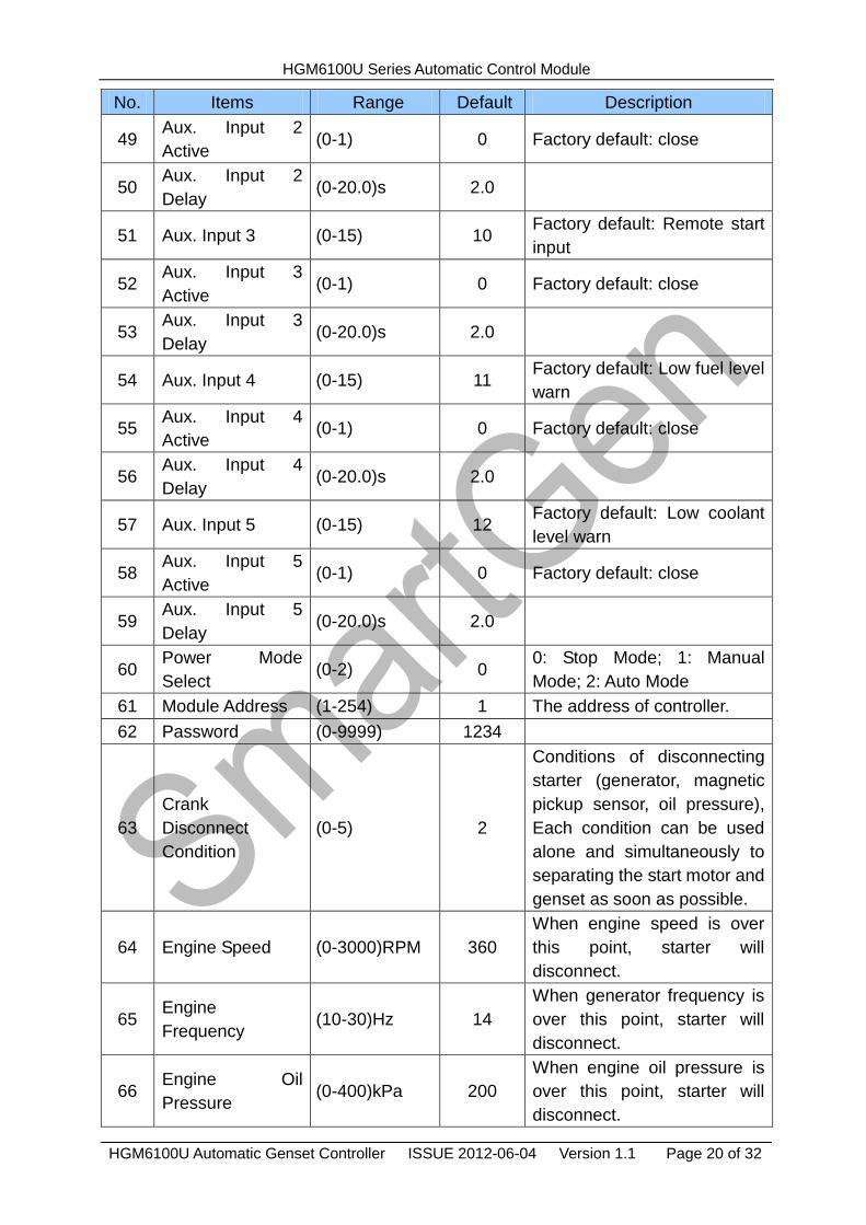
No. Items Range Default Description
49 Aux. Input 2
Active (0-1) 0 Factory default: close
50 Aux. Input 2
Delay (0-20.0)s 2.0
51 Aux. Input 3 (0-15) 10 Factory default: Remote start
input
52 Aux. Input 3
Active (0-1) 0 Factory default: close
53 Aux. Input 3
Delay (0-20.0)s 2.0
54 Aux. Input 4 (0-15) 11 Factory default: Low fuel level
warn
55 Aux. Input 4
Active (0-1) 0 Factory default: close
56 Aux. Input 4
Delay (0-20.0)s 2.0
57 Aux. Input 5 (0-15) 12 Factory default: Low coolant
level warn
58 Aux. Input 5
Active (0-1) 0 Factory default: close
59 Aux. Input 5
Delay (0-20.0)s 2.0
60 Power Mode
Select (0-2) 0
0: Stop Mode; 1: Manual
Mode; 2: Auto Mode
61 Module Address (1-254) 1 The address of controller.
62 Password (0-9999) 1234
63
Crank
Disconnect
Condition
(0-5) 2
Conditions of disconnecting
starter (generator, magnetic
pickup sensor, oil pressure),
Each condition can be used
alone and simultaneously to
separating the start motor and
genset as soon as possible.
64 Engine Speed (0-3000)RPM 360
When engine speed is over
this point, starter will
disconnect.
65 Engine
Frequency (10-30)Hz 14
When generator frequency is
over this point, starter will
disconnect.
66 Engine Oil
Pressure (0-400)kPa 200
When engine oil pressure is
over this point, starter will
disconnect.
HGM6100U Series Automatic Control Module
HGM6100U Automatic Genset Controller ISSUE 2012-06-04 Version 1.1 Page 21 of 32
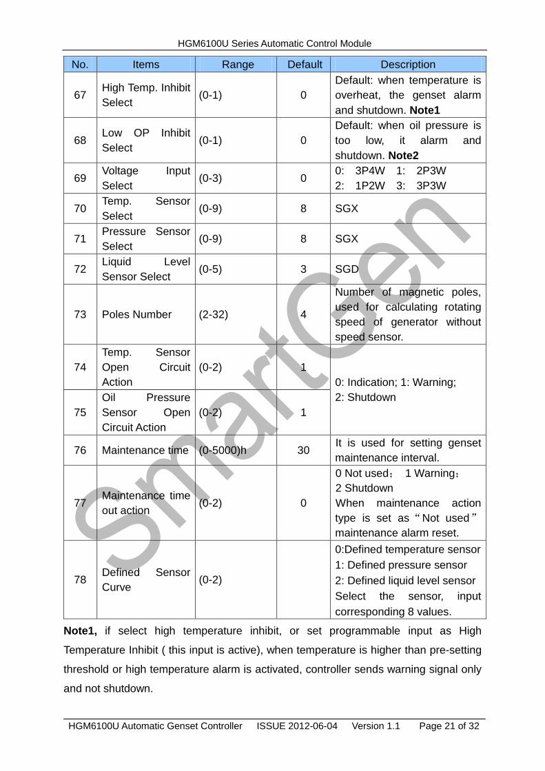
No. Items Range Default Description
67 High Temp. Inhibit
Select (0-1) 0
Default: when temperature is
overheat, the genset alarm
and shutdown. Note1
68 Low OP Inhibit
Select (0-1) 0
Default: when oil pressure is
too low, it alarm and
shutdown. Note2
69 Voltage Input
Select (0-3) 0
0: 3P4W 1: 2P3W
2: 1P2W 3: 3P3W
70 Temp. Sensor
Select (0-9) 8 SGX
71 Pressure Sensor
Select (0-9) 8 SGX
72 Liquid Level
Sensor Select (0-5) 3 SGD
73 Poles Number (2-32) 4
Number of magnetic poles,
used for calculating rotating
speed of generator without
speed sensor.
74
Temp. Sensor
Open Circuit
Action
(0-2) 1
0: Indication; 1: Warning;
2: Shutdown
75
Oil Pressure
Sensor Open
Circuit Action
(0-2) 1
76 Maintenance time (0-5000)h 30 It is used for setting genset
maintenance interval.
77 Maintenance time
out action (0-2) 0
0 Not used; 1 Warning;
2 Shutdown
When maintenance action
type is set as“Not used”
maintenance alarm reset.
78 Defined Sensor
Curve (0-2)
0:Defined temperature sensor
1: Defined pressure sensor
2: Defined liquid level sensor
Select the sensor, input
corresponding 8 values.
Note1, if select high temperature inhibit, or set programmable input as High
Temperature Inhibit ( this input is active), when temperature is higher than pre-setting
threshold or high temperature alarm is activated, controller sends warning signal only
and not shutdown.
HGM6100U Series Automatic Control Module
HGM6100U Automatic Genset Controller ISSUE 2012-06-04 Version 1.1 Page 22 of 32
Note2, if select low oil pressure inhibit, or set programmable input as Low Oil Pressure
Inhibit ( this input is active), when low oil pressure is lower than pre-setting threshold or
low oil pressure alarm is activated, controller sends warning signal only and not
shutdown.
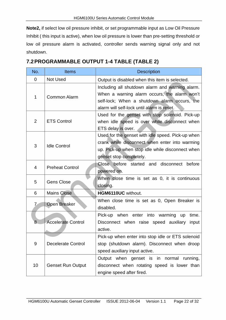
7.2 PROGRAMMABLE OUTPUT 1-4 TABLE (TABLE 2)
No. Items Description
0 Not Used Output is disabled when this item is selected.
1 Common Alarm
Including all shutdown alarm and warning alarm.
When a warning alarm occurs, the alarm won’t
self-lock; When a shutdown alarm occurs, the
alarm will self-lock until alarm is reset.
2 ETS Control
Used for the genset with stop solenoid. Pick-up
when idle speed is over while disconnect when
ETS delay is over.
3 Idle Control
Used for the genset with idle speed. Pick-up when
crank while disconnect when enter into warming
up. Pick-up when stop idle while disconnect when
genset stop completely.
4 Preheat Control Close before started and disconnect before
powered on.
5 Gens Close When close time is set as 0, it is continuous
closing.
6 Mains Close HGM6110UC without.
7 Open Breaker When close time is set as 0, Open Breaker is
disabled.
8 Accelerate Control
Pick-up when enter into warming up time.
Disconnect when raise speed auxiliary input
active.
9 Decelerate Control
Pick-up when enter into stop idle or ETS solenoid
stop (shutdown alarm). Disconnect when droop
speed auxiliary input active.
10 Genset Run Output
Output when genset is in normal running,
disconnect when rotating speed is lower than
engine speed after fired.
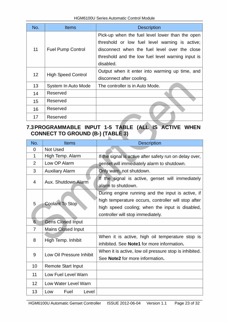
HGM6100U Series Automatic Control Module
HGM6100U Automatic Genset Controller ISSUE 2012-06-04 Version 1.1 Page 23 of 32
No. Items Description
11 Fuel Pump Control
Pick-up when the fuel level lower than the open
threshold or low fuel level warning is active;
disconnect when the fuel level over the close
threshold and the low fuel level warning input is
disabled.
12 High Speed Control Output when it enter into warming up time, and
disconnect after cooling.
13 System In Auto Mode The controller is in Auto Mode.
14 Reserved
15 Reserved
16 Reserved
17 Reserved
7.3 PROGRAMMABLE INPUT 1-5 TABLE (ALL IS ACTIVE WHEN CONNECT TO GROUND (B-) (TABLE 3)
No. Items Description
0 Not Used
1 High Temp. Alarm If the signal is active after safety run on delay over,
genset will immediately alarm to shutdown. 2 Low OP Alarm
3 Auxiliary Alarm Only warn, not shutdown.
4 Aux. Shutdown Alarm If the signal is active, genset will immediately
alarm to shutdown.
5 Coolant To Stop
During engine running and the input is active, if
high temperature occurs, controller will stop after
high speed cooling; when the input is disabled,
controller will stop immediately.
6 Gens Closed Input
7 Mains Closed Input
8 High Temp. Inhibit When it is active, high oil temperature stop is
inhibited. See Note1 for more information.
9 Low Oil Pressure Inhibit When it is active, low oil pressure stop is inhibited.
See Note2 for more information.
10 Remote Start Input
11 Low Fuel Level Warn
12 Low Water Level Warn
13 Low Fuel Level
HGM6100U Series Automatic Control Module
HGM6100U Automatic Genset Controller ISSUE 2012-06-04 Version 1.1 Page 24 of 32
No. Items Description
Shutdown
14 Low Water Level
Shutdown
15 Auto Start Inhibit
In Auto Mode, when the input is active, no matter
mains normal or not, genset won’t start. If genset
is in normal running, stop process won’t be
executed. When input is disabled, genset will
automatically start or stop judging by mains
normal or not.
7.4 SENSOR SELECTION (TABLE 4)
No. Items Content Description
1 Temperature
Sensor
0 Not used
1 Defined Resistance Type
2 VDO
3 SGH(Huanghe sensor)
4SGD(DongKang sensor)
5 CURTIS
6 DATCON
7 VOLVO-EC
8 SGX
9 Reserved
Defined input resistance
range is 0Ω~6000Ω, factory
default is SGX sensor.
2 Pressure
Sensor
0 Not used
1 Defined Resistance Type
2 VDO 10Bar
3 SGH(Huanghe sensor)
4 SGD(DongKang sensor)
5 CURTIS
6 DATCON 10Bar
7 VOLVO-EC
8 SGX
9 Reserved
Defined input resistance
range is 0Ω~6000Ω, factory
default is SGX sensor.
3 Fuel Level
Sensor
0 Not used
1 Defined Resistance Type
2 SGH
3 SGD
4 Reserved 1
5 Reserved 2
Defined input resistance
range is 0~6000Ω, factory
default is SGD sensor.
7.5 CONDITIONS OF CRANK DISCONNECT (TABLE 5)
No. Content
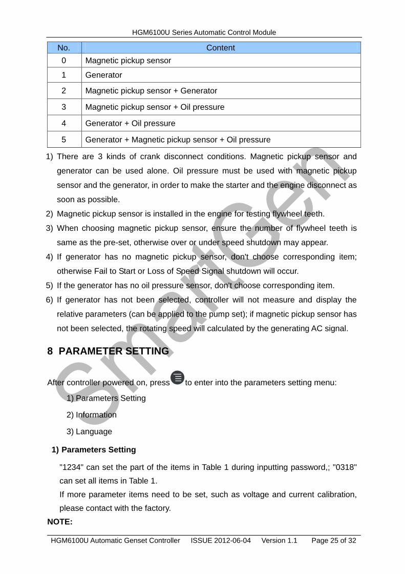
HGM6100U Series Automatic Control Module
HGM6100U Automatic Genset Controller ISSUE 2012-06-04 Version 1.1 Page 25 of 32
No. Content
0 Magnetic pickup sensor
1 Generator
2 Magnetic pickup sensor + Generator
3 Magnetic pickup sensor + Oil pressure
4 Generator + Oil pressure
5 Generator + Magnetic pickup sensor + Oil pressure
1) There are 3 kinds of crank disconnect conditions. Magnetic pickup sensor and
generator can be used alone. Oil pressure must be used with magnetic pickup
sensor and the generator, in order to make the starter and the engine disconnect as
soon as possible.
2) Magnetic pickup sensor is installed in the engine for testing flywheel teeth.
3) When choosing magnetic pickup sensor, ensure the number of flywheel teeth is
same as the pre-set, otherwise over or under speed shutdown may appear.
4) If generator has no magnetic pickup sensor, don't choose corresponding item;
otherwise Fail to Start or Loss of Speed Signal shutdown will occur.
5) If the generator has no oil pressure sensor, don't choose corresponding item.
6) If generator has not been selected, controller will not measure and display the
relative parameters (can be applied to the pump set); if magnetic pickup sensor has
not been selected, the rotating speed will calculated by the generating AC signal.
8 PARAMETER SETTING
After controller powered on, press to enter into the parameters setting menu:
1) Parameters Setting
2) Information
3) Language
1) Parameters Setting
"1234" can set the part of the items in Table 1 during inputting password,; "0318"
can set all items in Table 1.
If more parameter items need to be set, such as voltage and current calibration,
please contact with the factory.
NOTE:
HGM6100U Series Automatic Control Module
HGM6100U Automatic Genset Controller ISSUE 2012-06-04 Version 1.1 Page 26 of 32
1) HGM6110UC, there are not items 1-5 in table1; programmable output 1-4 have no
digital outputs about mains.
2) Please modify the parameters in standby mode (crank conditions, auxiliary input
and output configuration, multi delays, etc.) otherwise shutdown alarm or other
abnormal conditions may appear.
3) The over-voltage threshold must be greater than the under-voltage threshold;
otherwise over-voltage and under-voltage will occur at the same time.
4) The over-speed threshold must be greater than under-speed threshold, otherwise
over speed and under speed will occur at the same time.
5) Set frequency value (after crank disconnect) as low as possible, in order to
disconnect starter quickly.
6) Programmable input 1-5 cannot be set as the same items, otherwise it cannot
realize correct function; programmable output 1-4 can be set as the same item.
7) If need to shut down after cooling, please set any input as " stop after cooling ",
then connect this input to ground.
2) Information
LCD will display some information of controller, such as software version, issue date.
Note: Pressing will display the status of digital inputs and outputs.
3) Language
User may select display language as Chinese, English, Spanish and Russian.
4) LCD contract
Press and (or ) can adjust LCD contract. Adjustment range is 0-7.
Note: Pressing key at any time will exit the editor and back to main interface.
9 SENSOR SETTING
1) When choosing sensor, standard of sensor curve will be needed. If temperature
sensor is set as SGH (120ºC resistor type), sensor curve should be SGH (120oC
resistor type); If it is set as SGD (120ºC resistor type), sensor curve should be
SGD curve.
2) If there is difference between standard sensor curve and chosen sensor curve,
HGM6100U Series Automatic Control Module
HGM6100U Automatic Genset Controller ISSUE 2012-06-04 Version 1.1 Page 27 of 32
select "defined sensor", and then input defined sensor curve.
3) When sensor curve is inputted, X value (resistance) must be in accordance with
the order of higher to lower, otherwise errors will occur.
4) When sensor is selected as "Not used", temperature, pressure and fuel level will
be display as" - - -" in LCD.
5) If there is no pressure sensor, but only has low pressure alarm switch, then you
must set pressure sensor as "Not used", otherwise oil pressure low alarm
shutdown may appear.
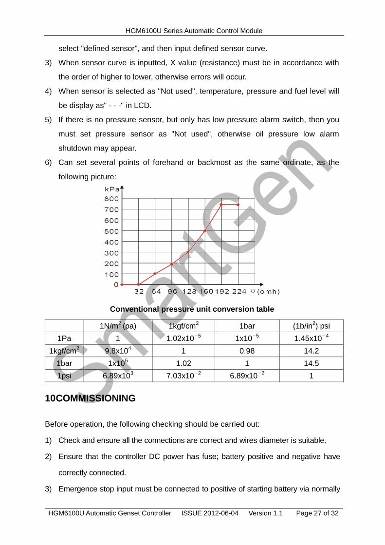
6) Can set several points of forehand or backmost as the same ordinate, as the
following picture:
Conventional pressure unit conversion table
1N/m2 (pa) 1kgf/cm2 1bar (1b/in2) psi
1Pa 1 1.02x10⁻⁵ 1x10
-5 1.45x10⁻⁴
1kgf/cm2 9.8x10⁴ 1 0.98 14.2
1bar 1x10⁵ 1.02 1 14.5
1psi 6.89x10³ 7.03x10⁻² 6.89x10
-2 1
10 COMMISSIONING
Before operation, the following checking should be carried out:
1) Check and ensure all the connections are correct and wires diameter is suitable.
2) Ensure that the controller DC power has fuse; battery positive and negative have
correctly connected.
3) Emergence stop input must be connected to positive of starting battery via normally
HGM6100U Series Automatic Control Module
HGM6100U Automatic Genset Controller ISSUE 2012-06-04 Version 1.1 Page 28 of 32
close contact of emergency stop.
4) Take proper actions to prevent engine to disconnect crank (e. g. Remove the
connections of fuel value). If checking is OK, connect start battery, select Manual
Mode, controller will execute the program.
5) Set controller as Manual Mode, press “start” button to start genset. If failed within the
setting crank times, controller will send “Failed to Start” signal; then press “stop” to
reset controller.
6) Recover actions of preventing engine to disconnect crank (e. g. Connect wire of fuel
value), press “start” button again, genset will start. If everything goes well, genset will
normal run after idle running (if configured). During this period, watch for engine’s
running situations and voltage and frequency of alternator. If there is abnormal, stop
genset and check all connections according to this manual.
7) Select the Auto Mode from front panel, connect to mains signal. After the mains
normal delay, controller will transfer ATS (if configured) into mains load. After cooling,
controller will stop genset and into standby state until mains abnormal again.
8) When mains abnormal again, genset will start automatically and into normal running,
send signal to make gens close, transfer ATS and make genset take load. If it not
likes this, please check connections of ATS according to this manual.
9) If there are any other questions, please contact Smartgen’s service.
HGM6100U Series Automatic Control Module
HGM6100U Automatic Genset Controller ISSUE 2012-06-04 Version 1.1 Page 29 of 32
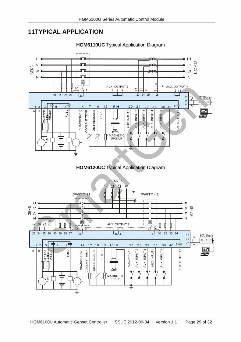
11 TYPICAL APPLICATION
HGM6110UC Typical Application Diagram
HGM6120UC Typical Application Diagram
HGM6100U Series Automatic Control Module
HGM6100U Automatic Genset Controller ISSUE 2012-06-04 Version 1.1 Page 30 of 32
Single Phase 2 Wire
2 Phase 3 Wire
Note: Recommend that the output of crank and Fuel expand high capacity relay.
12 INSTALLATION
12.1 FIXING CLIPS
The module is held into the panel fascia using the supplied fixing clips.
1) Withdraw the fixing clip screw (turn anticlockwise) until it reaches proper position.
2) Pull the fixing clip backwards (towards the back of the module) ensuring four clips
are inside their allotted slots.
3) Turn the fixing clip screws clockwise until they make contact with the panel.
Note: Care should be taken not to over tighten the screws of fixing clips.
HGM6100U Series Automatic Control Module
HGM6100U Automatic Genset Controller ISSUE 2012-06-04 Version 1.1 Page 31 of 32
12.2 OVERALL DIMENSION AND PANEL CUTOUT
1) Battery Voltage Input
HGM6100U series controller can be applicable to (8~35) VDC battery voltage.
Battery negative must be reliably connected to engine shell. The connection
between controller power and battery should not be less than 2.5mm2. If a float
charger is fitted, please connect output line of the charger with battery directly, and
then connect battery positive and negative to power input of controller separately,
in case that charger will interfere with the normal running of controller.
2) Speed Sensor Input
Speed sensor is installed in the engine for testing flywheel teeth. The connection
with controller uses 2-core screen, shield layer should be connected to terminal16
of controller and the other end vacant. The other two signal lines are respectively
connected to terminal15 and terminal16. At full speed, output voltage range is
(1~24) VAC (RMS), 12VAC is recommended (rated speed). During installing,
make the speed sensor contact the flywheel firstly, then pour out 1/3 laps, finally
lock nut on the sensor.
3) Output And Expansion Relay
All the outputs of controller are relay output. If need to expand relay, please add
freewheeling diode in both ends of relay coil (when expansion relay coil links DC),
or add RC loop (when expansion relay coil links AC), in case controller or other
equipments are interfered.
4) AC Input
HGM6100U series controller must externally connect to current transformer; CT
secondary current must be 5A. Besides, the phase of CT and input voltage must
be correct, or the sampling current and active power may be incorrect.
HGM6100U Series Automatic Control Module
HGM6100U Automatic Genset Controller ISSUE 2012-06-04 Version 1.1 Page 32 of 32
Note: A. ICOM must connect to battery cathode of the controller.
B. When there is load current, open circuit is inhibited in the CT secondary side.
5) Dielectric Strength test
When the controller has been installed in the control panel, during the test please
disconnect all the terminals, in case high voltage damages the controller.
13 FAULT FINDING
Symptoms Possible Solutions
Controller Inoperative
Check starting battery;
Check connections of controller.
Check the DC fuse.
Genset Stops
Check if water/cylinder temperature too high.
Check alternator voltage.
Check the DC fuse.
Emergency Stop
Check if an emergency stop button is fitted; Ensure
battery positive is connected to the emergency stop
input.
Check if connection is open circuit.
Low Oil Pressure Alarm (After
Crank Disconnect) Check oil pressure sensor and connections.
High Temp. Alarm (After
Crank Disconnect) Check temperature sensor and connections.
Shutdown Alarm During
Running
Check switch and connections according to
information on LCD.
Check configurable inputs.
Crank Disconnect Failed
Check connections of fuel solenoid.
Check starting battery.
Check speed sensor and its connections. Refer to
engine manual.
Starter Inoperative Check connections of starter;
Check starting battery.
Genset Running While ATS
Not Transfer
Check ATS;
Check connections between ATS and controller.
RS485 Failure
Check connections;
Check if COM port is correct;
Check if A and B of RS485 is connected reversely;
Check if PC COM port is damaged;
120Ω resistance between PR485 and AB is
Recommended.