Embed Size (px)
Citation preview

HGM-1, 2 & 3 BS, TS Bottom / Top Mount
Medium TemperatureRemote and Self Contained
Glass Door Merchandisers
Installation & Service Manual
P/N 0515297_B January 2012
P/N0515297B
IMPORTA
NT
Keep in
store f
or futur
e refere
nce!
®
HGM-3BS HGM-2TS


IMPORTANTKEEP IN STORE FOR FUTURE REFERENCE
Quality that sets industry standards!
12999 St. Charles Rock Road • Bridgeton, MO 63044-2483
U.S. & Canada 1-800-922-1919 • Mexico 1-800-522-1900
www.hussmann.com© 2012 Hussmann Corporation
®
P/N 0515297_B iii


ANSI DEFINITIONS . . . . . . . . . . . . . . . . . vi
INSTALLATION
Certification . . . . . . . . . . . . . . . . . . . . . . . . 1-1Hussmann Product Control . . . . . . . . . . . 1-1Shipping Damage . . . . . . . . . . . . . . . . . . . 1-1Location . . . . . . . . . . . . . . . . . . . . . . . . . . . 1-1Self Contained (Location) . . . . . . . . . . . . 1-2Model Description . . . . . . . . . . . . . . . . . . 1-4Unloading . . . . . . . . . . . . . . . . . . . . . . . . . 1-4Exterior Loading . . . . . . . . . . . . . . . . . . . . 1-4Shipping Skid . . . . . . . . . . . . . . . . . . . . . . 1-4Merchandiser Leveling . . . . . . . . . . . . . . . 1-5Leg Installation . . . . . . . . . . . . . . . . . . . . . 1-5Serial Plate Location . . . . . . . . . . . . . . . . . 1-5Refrigeration Unit Access . . . . . . . . . . . . . 1-6Sealing Merchandiser to Floor . . . . . . . . . 1-5Air Distribution & Rear Flue Spacer . . . . 1-6Shelves . . . . . . . . . . . . . . . . . . . . . . . . . . . . 1-6
ELECTRICAL / REFRIGERATION
Merchandiser Electrical Data . . . . . . . . . . 2-1Field Wiring . . . . . . . . . . . . . . . . . . . . . . . 2-1Electrical Connections . . . . . . . . . . . . . . . 2-1Electrical Outlet . . . . . . . . . . . . . . . . . . . . 2-1Refrigeration (Self Contained) . . . . . . . . . 2-1Line Sizing (Remote Models) . . . . . . . . . . 2-2Oil Traps . . . . . . . . . . . . . . . . . . . . . . . . . . . . . . . . . 2-2Pressure Drop . . . . . . . . . . . . . . . . . . . . . . . . . . . . . 2-2Water Outlet and Water Seal . . . . . . . . . . 2-2
START UP / OPERATION
Start-Up . . . . . . . . . . . . . . . . . . . . . . . . . . . 3-1Operation . . . . . . . . . . . . . . . . . . . . . . . . . . 3-1Power Switch . . . . . . . . . . . . . . . . . . . . . . . . . . . . . 3-1Light Switch . . . . . . . . . . . . . . . . . . . . . . . . . . . . . . 3-1Electromechanical Control . . . . . . . . . . . . . . . . . . 3-1Safe NET III User Instructions . . . . . . . . 3-2Start-Up . . . . . . . . . . . . . . . . . . . . . . . . . . . 3-3Sequence of Operation . . . . . . . . . . . . . . . 3-5Temperature Adjustment . . . . . . . . . . . . . 3-6Alarms and Codes . . . . . . . . . . . . . . . . . . . 3-6Defrost Termination Switch . . . . . . . . . . . 3-6
Manual Defrost . . . . . . . . . . . . . . . . . . . . . 3-6Temperature Adjustment . . . . . . . . . . . . . 3-7Sensor to Control Configuration . . . . . . . 3-8Lighting . . . . . . . . . . . . . . . . . . . . . . . . . . . 3-9LED Lights . . . . . . . . . . . . . . . . . . . . . . . . 3-9Door Defrost Heater Thermostat . . . . . . . 3-9Controls and Adjustments . . . . . . . . . . . 3-10Refrigerant Control . . . . . . . . . . . . . . . . . 3-10Load Limits . . . . . . . . . . . . . . . . . . . . . . . 3-11Stocking . . . . . . . . . . . . . . . . . . . . . . . . . . 3-11NOTES: . . . . . . . . . . . . . . . . . . . . . . . . . . 3-12
MAINTENANCE
Care and Cleaning . . . . . . . . . . . . . . . . . . . 4-1Exterior Surfaces . . . . . . . . . . . . . . . . . . . . . . . . . . 4-1Interior Surfaces . . . . . . . . . . . . . . . . . . . . . . . . . . . 4-1Do NOT Use: . . . . . . . . . . . . . . . . . . . . . . 4-1Do: . . . . . . . . . . . . . . . . . . . . . . . . . . . . . . . 4-1Cleaning Stainless Steel Surfaces . . . . . . . 4-2Cleaning Coils . . . . . . . . . . . . . . . . . . . . . . 4-2Cleaning Evaporation Pan . . . . . . . . . . . . 4-3NOTES: . . . . . . . . . . . . . . . . . . . . . . . . . . . 4-4
SERVICE
Replacing Fan Motors and Blades . . . . . . 5-1Replacing Thermometer . . . . . . . . . . . . . . 5-1Trouble Shooting Guide . . . . . . . . . . . . . . 5-2
APPENDIX
Part Numbers . . . . . . . . . . . . . . . . . . . . . . A-1HGM-1BS — Plan View . . . . . . . . . . . . . A-2HGM-2BS & HGM-2BS — Plan View . . A-3HGM-1TS — Plan View . . . . . . . . . . . . . . A-4HGM-2TS — Plan View . . . . . . . . . . . . . . A-5HGM-3TS — Plan View . . . . . . . . . . . . . . A-6Dimensions & Electrical Data . . . . . . . . . A-7Cross Sections and Refrigeration Data . . A-8Wiring Diagram — Remote . . . . . . . . . . . A-9Wiring Diagram — Self Contained . . . . A-10
WARRANTY
TABLE OF CONTENTS v
HUSSMANN CORPORATION • BRIDGETON, MO 63044-2483 U.S.A. HGM Merchandisers

REVISION HISTORY
REVISION B — Changed fonts and replacedrevision level to B for Wind Chill
ORIGINAL ISSUE — JANUARY 2011
vi
P/N 0515297_B U.S. & Canada 1-800-922-1919 • Mexico 1-800-522-1900 • www.hussmann.com
* * * * * * * * * * * * * * * * * * * * * * * * * *ANSI Z535.5 DEFINITIONS
• DANGER – Indicate[s] a hazardoussituation which, if not avoided, willresult in death or serious injury.
• WARNING – Indicate[s] a hazardoussituation which, if not avoided, couldresult in death or serious injury.
• CAUTION – Indicate[s] a hazardoussituation which, if not avoided, couldresult in minor or moderate injury.
• NOTICE – Not related to personal injury –Indicates[s] situations, which if not avoided,could result in damage to equipment.

P/N 0515297_B 1-1
HUSSMANN CORPORATION • BRIDGETON, MO 63044-2483 U.S.A. HGM Merchandisers
CERTIFICATION
These merchandisers are manufactured to meetANSI / National Sanitation Foundation(NSF®) Standard #7 requirements. Properinstallation is required to maintain certification.Near the serial plate, each case carries a labelidentifying the type of application for whichthe case was certified.
ANSI/NSF-7 Type I - Display Refrigerator / FreezerIntended for 75°F / 55% RH Ambient Application
ANSI/NSF-7 Type II - Display Refrigerator / FreezerIntended for 80°F / 55% RH Ambient Application
ANSI/NSF-7 - Display RefrigeratorIntended for Bulk Produce
HUSSMANN PRODUCT CONTROL
The serial number and shipping date of allequipment is recorded in Hussmann’s files forwarranty and replacement part purposes. Allcorrespondence pertaining to warranty orparts ordering must include the serial numberof each piece of equipment involved. This is toensure the customer is provided with the correctparts.
SHIPPING DAMAGE
All equipment should be thoroughly examinedfor shipping damage before and during unloading. This equipment has been carefullyinspected at our factory. Any claim for loss ordamage must be made to the carrier. The carrier will provide any necessary inspectionreports and/or claim forms.
Apparent Loss or Damage
If there is an obvious loss or damage, it mustbe noted on the freight bill or express receiptand signed by the carrier’s agent; otherwise,carrier may refuse claim.
Concealed Loss or Damage
When loss or damage is not apparent untilafter equipment is uncrated, retain all packingmaterials and submit a written response to thecarrier for inspection within 15 days.
LOCATION
These merchandisers are designed for displaying products in air conditioned storeswhere temperature is maintained at or belowthe ANSI / NSF-7 specified level and relativehumidity is maintained at or below 55%.
Placing refrigerated merchandisers in directsunlight, near hot tables or near other heatsources could impair their efficiency. Likeother merchandisers, these merchandisers aresensitive to air disturbances. Air currents passing around merchandisers will seriouslyimpair their operation. Do NOT allow air conditioning, electric fans, open doors or windows, etc. to create air currents around themerchandiser.
INSTALLATION
Recommended operating ambient temperature is between
65°F (18°C) to 75°F (23.9°C). Maximum relative humidity is 55%.

1-2 INSTALLATION
SELF CONTAINED (LOCATION)
Product should always be maintained at proper temperature. This means that from the time theproduct is received, through storage, preparationand display. The temperature of the productmust be controlled to maximize the life of theproduct.
BE SURE TO POSITION SELF CONTAINED
MERCHANDISERS PROPERLY.
HGM-TS Location
The condensing unit is located at the top ofthe HGM-TS. At least 12 inches of clearanceshould be allowed at the rear of the cabinet andat the top of the merchandiser. This clearance isnecessary to provide free air movement to andfrom the condensing unit for maximum operating efficiency.
P/N 0515297_B U.S. & Canada 1-800-922-1919 • Mexico 1-800-522-1900 • www.hussmann.com

P/N 0515297_B 1-3
HGM-BS Location
At least 24 inches of clearance should be maintained in front of HGM-BS merchandisersand 6 inches of clearance at the rear to providethe necessary free air movement to and fromthe condensing unit. The condensing unit islocated at the bottom of these merchandisers.
HUSSMANN CORPORATION • BRIDGETON, MO 63044-2483 U.S.A. HGM Merchandisers

1-4 INSTALLATION
MODEL DESCRIPTION
The HGM-BS/TS models are self-contained,medium temperature, vertical glass door merchandisers designed for the display of dairyproducts, deli items and beverages. Design features include self-closing glass doors, efficient foamed in place non-CFC insulationand balanced R-134a refrigeration systems forenergy saving performance.
UNLOADING
Unloading from Trailer:Lever Bar (also known as a Mule, JohnsonBar, J-bar, Lever Dolly, or Pry Lever)
Move the merchandiser as close as possible toits permanent location and remove all packaging.Check for damage before discarding packaging.Remove all separately packed accessories suchas kits and shelves.
Improper handling may cause damage to themerchandiser when unloading. To avoid damage:
1. Do not drag the merchandiser out of thetrailer. Use a Johnson bar (mule).
2. Use a forklift or dolly to remove the merchandiser from the trailer.
EXTERIOR LOADING
Do NOT walk on top of merchandisers or damage to the merchandisers and serious personal injury could occur.
MERCHANDISERS ARE NOT STRUCTURALLY
DESIGNED TO SUPPORT EXCESSIVE EXTERNAL
LOADING such as the weight of a person. Donot place heavy objects on the merchandiser.
SHIPPING SKID
Each merchandiser is shipped on a skid to protect the merchandiser’s base, and to make positioning the case easier.
Remove the top of the crate and detach wallsfrom each other. Lift crate from the skid.Unscrew the case from the skid. The fixturecan now be lifted off the crate skid. Lift only atbase of skid! Remove any braces and/or skidsattached (blanket wrapped merchandiser mayhave skids).
DO NOT TILT MERCHANDISER ON ITSSIDE OR END WHEN REMOVING SKID.
Tilting merchandiser could cause damage tothe refrigeration system.
Once the skid is removed, the merchandisermust be lifted —NOT PUSHED— to reposition.To remove the skid, remove screws attachingskid to the merchandiser.
Check floor where cases are to be set to see ifit is a level area. Determine the highest part ofthe floor.
Unpack door and all packaged accessories.
P/N 0515297_B U.S. & Canada 1-800-922-1919 • Mexico 1-800-522-1900 • www.hussmann.com
Do NOT remove shipping crate until themerchandiser is positioned
for installation.
Do not walk or put heavy objects on case.

MERCHANDISER LEVELING
BE SURE TO POSITION MERCHANDISERS PROPERLY.Level the merchandiser at corners.
Merchandiser(s) must be installed level toensure proper operation of the refrigerationsystem and to ensure proper drainage ofdefrost water. The merchandiser can be leveledby shimming under the cabinet base frame, orby installing optional leg levelers.
The self-closing doors require the cabinet to beproperly leveled. End to end leveling will allowthe door(s) to close with uniform speed and tightness. A slight pitch from front to rear isdesirable. THE BACK OF MERCHANDISER
SHOULD NEVER BE HIGHER THAN THE FRONT.
LEG INSTALLATION (Top Mounts Only)
Install the NSF approved legs after the case isnear its final location. The legs are packagedinside the cabinet. Replace the tape and doorblocks.
To install legs:
Raise one end of the cabinet about 8 inches.Block the merchandiser securely, and install twolegs. The leg mounting plates are factoryinstalled and contain a 1/2 x 13 in. tapped holeto mate with the leg assembly. The procedure isrepeated on the opposite end. Three-door merchandisers require legs in the center.
The cabinet should now be positioned at itsfinal location with all legs installed. The merchandiser is leveled by turning the bottomsection of each leg . End to end leveling willmake the door(s) close with uniform speed andtightness. A slight pitch from front to rear isdesirable.
SERIAL PLATE LOCATION
The serial plate is located in the upper left-hand corner of the merchandiser’s interior. Theserial plate contains all pertinent informationsuch as model, serial number, amperage rating,refrigerant type and charge. Do not remove theserial plate under any circumstance.
P/N 0515297_B 1-5
HUSSMANN CORPORATION • BRIDGETON, MO 63044-2483 U.S.A. HGM Merchandisers
Serial Plate

1-6 INSTALLATION
REFRIGERATION UNIT ACCESS
Top Mounts — The top decorative panel isremoved by lifting the panel up and pullingforward.Bottom Mounts — The lower front panel maybe removed by removing screw at bottom andlifting the panel straight upward and over thetabs on which it is hanging. The panel isinstalled by reversing the above procedure.
Ensure lower front panel is flat against thefloor when installed to prevent air circulationproblems for self contained merchandisers.If the condensing unit needs to be serviced, itcan be pulled out to gain access for hard toreach components like the condenser fans. To pull out the condensing unit, remove thetwo hold down brackets at the unit base.
Care must be given to the drain line when replacing the condensing unit into the case.The drain line must be inside the defrost waterevaporation pan to prevent the discharge ofwater on the floor.
SEALING MERCHANDISER TO FLOOR(Bottom Mounts Only)
If required by local sanitary codes, or if thecustomer desires, merchandisers may be sealedto the floor using a vinyl cove base trim. The size needed will depend on how much variationthere is in the floor, from one end of the merchandiser to the other. Sealing of the lower
front and rear panels on self contained modelsmay hamper their removal for servicing ormaintenance of the condensing unit.
NOTE: Do not allow trim to cover any intakeor discharge grilles located in the lower frontpanel.
AIR DISTRIBUTION & REAR FLUE SPACER
Air is drawn through the evaporator from frontto rear and is discharged down the back wall,returning up the face of the glass door to thereturn air grille.
NOTE: Rear flue spacer must be in place asthis forms a discharge air flue at the back ofthe cabinet.
SHELVES
Each cabinet is provided with four cantilevershelves per door that are adjustable by 1 inchincrements. The shelves can also be tilted. Eachcabinet has one bottom shelf per door. Theseshelves have one-inch legs to allow proper airflow in the cabinet. Behind the shelves are wireflues spacers, which allow for proper air flow.All shelves and flue spacers are white andepoxy coated for durability and ease of cleaning.
Shelves should be adjusted to desired operatingheight. Do not load product so that it touchesthe evaporator coil cover. Do not extend productpast the front edge of the shelf. Extending pastthe edge will seriously affect internal air flowthrough the cabinet.
Shelves are UL rated for a maximum load of120 lbs. DO NOT OVERLOAD THE SHELVES.
P/N 0515297_B U.S. & Canada 1-800-922-1919 • Mexico 1-800-522-1900 • www.hussmann.com
Lift up andout to removeaccess panel
First
Then

P/N 0515297_B 2-1
HUSSMANN CORPORATION • BRIDGETON, MO 63044-2483 U.S.A. HGM Merchandisers
MERCHANDISER ELECTRICAL DATA
Refer to Appendix A of this manual or themerchandiser’s serial plate for electrical information.
FIELD WIRING
Field wiring must be sized for componentamperes stamped on the serial plate. Actualampere draw may be less than specified.
ELECTRICAL CONNECTIONS
All wiring must be in compliance with NECand local codes. All electrical connections (forHGM-3 and all remote models) are to be madein the electrical Handy Box located behind theremovable base panel at the right end of themerchandiser when facing the discharge honeycomb. The cabinet supply breakersshould be disconnected before removing theenclosure cover.
ELECTRICAL OUTLET:
Before the merchandiser is connected to anywall circuit, use a voltmeter to check that theoutlet is within the recommended voltage limits:
The wall circuit must be dedicated for the merchandiser. Failure to do so voids the warranty. Do not use an extension cord. Neverplug in more than one merchandiser per electrical circuit.
• Always use a dedicated circuit with the amperage stated on the unit.
• Plug into an outlet designed for the plug.• Do not overload the circuit• Do not use long or thin extension cords.Never use adapters.
• If in doubt, call an electrician.
The HGM-1 and HGM-2 self-contained mer-chandisers are supplied with a supply cord and agrounding prong for operation on a 115V powersupply.
HGM-3 requires hard wiring to a 30 amp, 115Vcircuit.
REFRIGERATION(Self Contained Models)
Each self contained model is equipped withits own condensing unit and control panellocated beneath the display area. The correcttype of refrigerant will be stamped on eachmerchandiser’s serial plate. The merchandiserrefrigeration piping is leak tested. The unit ischarged with refrigerant, and shipped fromthe factory with all service valves open.
ELECTRICAL / REFRIGERATION
ALWAYS CHECK THE SERIAL PLATE FOR COMPONENT AMPERES
Nominal Volts 120V
Minimum Volts 108V
Maximum Volts 132V

2-2 INSTALLATION
P/N 0515297_B U.S. & Canada 1-800-922-1919 • Mexico 1-800-522-1900 • www.hussmann.com
LINE SIZING(Remote Models)
Refrigerant line connections are made at theright end of merchandiser (facing front)beneath the refrigerated display area. Therefrigerant line connection size is 3/8 in. Thesuction line is 5/8 in. Refrigerant lines should besized as shown on the refrigeration legend thatis furnished for the store or according toASHRAE guidelines.
Oil Traps
P-traps (oil traps) must be installed at the baseof all suction line vertical risers.
Pressure DropKeep refrigerant line runs as short as possibleto avoid large pressure drops. Use a minimumnumber of elbows. Where elbows are required,USE LONG RADIUS ELBOWS ONLY.
WATER OUTLET AND WATER SEAL
The cabinet is provided with a factory installedoutlet for defrost water. It runs from the bottom of the display area to an evaporationpan near the condenser unit.
The outlet is not connected to the waste watersystem for washing out the cabinet. This systemis designed to evaporate normal condensate.This system should be checked regularly, especiallyduring high relative humidity conditions, toverify the condensate tube is not blocked, andthat the pan does not accumulate too muchwater which could spill out on the floor.
Refrigeration lines are under pressure.Refrigerant must be recovered beforeattempting any connection or repair.
When brazing pipes, be sure to use theinsulation blanket shipped with the
merchandiser to prevent damage to themetal merchandiser bottom.
Product will be degraded and may spoil ifallowed to sit in a non-refrigerated area.
Merchandiser must be grounded.Do not remove the power supply cord ground.
Risk of Electric Shock. If cord or plug becomes damaged, replace only with
a cord and plug of the same type.
— LOCK OUT / TAG OUT —To avoid serious injury or death from electricalshock, always disconnect the electrical powerat the main disconnect when servicing orreplacing any electrical component. Thisincludes, but is not limited to, such items asdoors, lights, fans, heaters, and thermostats.

P/N 0515297_B 3-1
HUSSMANN CORPORATION • BRIDGETON, MO 63044-2483 U.S.A. HGM Merchandisers
START UP
1. Check the cabinet thoroughly for loose nuts and bolts and electrical connections. Inspect the refrigeration lines for any visable damage or chafing.
2. Replace the electrical box cover.
3. Start the merchandiser and allow the merchandiser to pull down to operating temperature.
The merchandiser must operate for 24 hoursbefore loading product. Regularly check temperatures. Do not break the cold chain.Keep products in cooler before loading merchandiser. These merchandisers are designedfor pre-chilled product only.
Under normal conditions, after the cabinet isinstalled and running, very little maintenanceshould be required. Follow the list of instruc-tion below after initial startup and for periodicmaintenance purposes.
1. Check operation of condenser fan motors.Fan blades must turn freely.
2. Check drain pan and heater to prevent accidental overflow.
3. Make sure doors are closing properly and that the gaskets seal.
4. Make sure all evaporator fan motors are running. These can be seen through the grille inside the cabinet.
OPERATION
Power Switch
The power switch is located at the electricalbox behind the top, decorative panel (TS models)or bottom louvered panel (BS models). Theswitch will shut off all power to the merchandiser.
Light Switch
Each HGM model has a convenient ON/OFFswitch so lights may be turned off to conserveenergy during hours when the store is closed. Theswitch only controls the lights.
Electromechanical Control
The electrical temperature control is located inthe electrical box. The temperature controldoes not have an “OFF” position.
Adjustments may be made by turning the knobon the face of the dial. Turning it clockwiseincreases temperature, counter-clockwisedecreases temperature.
There is also an adjustable temperature differential(the difference between the cut in temperatureand the cut-out temperature) located on theback of the temperature control cover. Whenadjusting the differential, the temperature setting may also have to be adjusted.
The control has a range of -20º F to +220º Fwith a differential of 1º to 30º. It is factory setfor approximately 29º F with a 10º differential.The temperature should be checked with athermometer other than the case thermometerafter is running to ensure that the merchandiseris running at the proper temperature for theproduct.
START UP / OPERATION
Product will be degraded and may spoil ifallowed to sit in a non-refrigerated area.

3-2 START UP / OPERATION
P/N 0515297_B U.S. & Canada 1-800-922-1919 • Mexico 1-800-522-1900 • www.hussmann.com
Safe-NET III™ TEMPERATURE AND DEFROST
CONTROLLER
SAFE-NET III™ USER INSTRUCTIONS
Your refrigerated case uses a Hussmann Safe-NET™ III temperature and defrost controller to precisely maintain the tempera-ture and prevent frost buildup on the coolingcoil. LEDs indicate when the compressor orrefrigeration is on, when the case is in a defrostcycle, if the temperature is outside the desiredrange, or if there is a sensor failure.
An adjustment knob allows the temperature tobe set within the configured range and canpower off the controller and compressor. Yourcontroller has been custom-configured to pro-vide the best temperature and defrost controlfor your chilled or frozen food.
The front of the controller has an adjustmentknob and status LEDs. The back of the controller has connections for sensors andswitched equipment.
The Safe-NET III controller includes the following features and connections.• Adjustment knob:Adjusts the temperature setpoint.Turn adjustment knob to OFF to turn offrefrigeration system. Unplug merchandiserfrom power before servicing the unit.
• Controller LEDs:Compressor Powered On LED (green):Lights while the compressor is running orthe refrigeration valve is open.Defrost Cycle LED (yellow):Lights while the refrigeration coil isdefrosting. Temperature or Sensor Alarm (red):Lights if the temperature is too warm ortoo cold. Flashes if a sensor fails.
START UP / OPERATION
It is the contractor’s responsibility toinstall merchandiser(s) in accordance with
all local building and health codes.
INSTALLER

P/N 0515297_B 3-3
HUSSMANN CORPORATION • BRIDGETON, MO 63044-2483 U.S.A. HGM Merchandisers
• Rear connections:– Case temperature sensor:• Typically senses the temperature of the air in the case.Used by the controller to determine whento power on or power off the compressoror refrigeration.
– Evaporator temperature sensor:• Senses the temperature of the refrigeration coil.Terminates a defrost cycle when refrigeration coil ice melts.
– Compressor or refrigeration relay:• Switches on the compressor or refrigeration valve for cooling.
DISPLAY
The display includes three red LEDs and twodigits for temperature, defrost status, and errorcodes.
The three display LEDs are red, and theirbehavior matches the LEDs on the controller.
START-UP
Before applying power to the merchandiser,remove the front grille.
Locate the compressor (for self containedmodels), CUT THE BAND HOLDING THECOMPRESSOR IN PLACE. This band is only neededfor shipment, and must be cut prior to operation.
Check thermostat knob is at the appropriateposition. See temperature adjustment on Page 3-6.
Check the check the merchandiser’s cabinetthoroughly for loose nuts and bolts. Check allelectrical connections. Inspect the refrigerantlines for any visible damage or chafing.
Replace the front grille.
The following list of housekeeping practiceswill assure trouble-free operation:
• Check operation of condenser fan motors. Fan blades must turn freely.
• Check drain pan and heater to prevent accidental overflow.
• Make sure doors are closing properly, and that gaskets are sealed.
• Make sure all evaporator fan motors are running. These can be seen through grille inside of cabinet.
The optional evaporator fan remainsON when the adjustment knob is in theOff position.

3-4 START UP / OPERATION
P/N 0515297_B U.S. & Canada 1-800-922-1919 • Mexico 1-800-522-1900 • www.hussmann.com
1. Plug in the merchandiser.
2. Wait for the self check to complete. Duringthe self check, each LED flashes for onesecond, then all LEDs turn on for two seconds. If the LEDs do not flash, makesure the adjustment knob is not in the Offposition.
• After the self check, all LEDs turn offuntil the compressor starts. There may be adelay before the compressor starts. If thered Temperature or Sensor Alarm LEDstays on after the self check.
• The green Compressor Powered On LEDturns on when the compressor starts.
NOTE: Do NOT load product until AFTERmerchandiser operates for 24 hours and reachesdesired operating temperature.
The OFF Position does not disconnect linevoltage to the case, refrigeration unit, fan,or heater.
Product will be degraded and may spoil ifallowed to sit in a non-refrigerated area.

P/N 0515297_B 3-5
HUSSMANN CORPORATION • BRIDGETON, MO 63044-2483 U.S.A. HGM Merchandisers
1. Apply power to the merchandiser. Wait forthe self check to complete. During the selfcheck, each LED flashes for one second andthen all LEDs turn on for two seconds. If theLEDs do not flash, make sure the adjustmentknob is not in the “OFF” position. If theadjustment knob is in the “OFF” position, thedisplay will also be blank.
2. The compressor will start after a delay; 30 seconds after the power is applied.
3. The compressor will continue to run until itreaches its cut-out temperature (pull down).
4. The refrigeration cycle will continue until thenext scheduled defrost (12 hours).
5. The above process will repeat (steps 3 and 4)until the power is interrupted.
6. If power stops, the process will start over at step1, and the time to subsequent defrost will reset.

3-6 START UP / OPERATION
P/N 0515297_B U.S. & Canada 1-800-922-1919 • Mexico 1-800-522-1900 • www.hussmann.com
TEMPERATURE ADJUSTMENT
Rotate the adjustment knob counter clockwisefor a warmer setpoint or clockwise for a coldersetpoint.
• While the temperature is being adjusted,the optional display shows the setpoint (cutout value). The display reverts to showingthe sensed temperature in the merchandisera few seconds after the temperature is set.
ALARMS AND CODES
FLASHING TEMPERATURE OR SENSOR ALARMLED, E1 OR E2If the Temperature or Sensor Alarm LED(red) on the controller and display is flashing,a temperature sensor has failed. The displayshows E1 if the case sensor has failed or E2 ifthe evaporator sensor has failed.
If the merchandiser sensor fails, refrigerationwill run continuously. Turn off, or repeat aduty cycle of a few minutes on and a few minutes off.
DEFROST TERMINATION SWITCH
Merchandisers may use a defrost terminationswitch, instead of an evaporator sensor to terminate a defrost cycle. The defrost termination switch is temperature activatedand senses the completion of defrost.
MANUAL DEFROST
Note: This procedure initiatesa manual or forceddefrost.
IMPORTANT: Return the control knob to itsoriginal setting (Step 1) once the manualdefrost has been initiated.

P/N 0515297_B 3-7
HUSSMANN CORPORATION • BRIDGETON, MO 63044-2483 U.S.A. HGM Merchandisers
TEMPERATURE ADJUSTMENT
1. Rotate the adjustment knob counter clock-wise for a hammer setpoint or clockwise fora colder setpoint.
2. While adjusting the temperature, the displayshows the setpoint (cut out value). A few seconds after the temperature is set, the controller reverts to the sensed temperaturein the merchandiser.
3. To verify merchandiser settings, perform theoperations below. Output readings should bewithin one degree of the temperaturesshown above.
The control has protective settings to preventshort cycling of the compressor.
A. The compressor may run for up to 3 min. after Step 2 is completed. Start the 10 sec. count down for Step 3, once the display is blank.
B. The defrost initiation may be delayed for upto 6 min. after Step 3 is completed.
The display will show the temperature prior todefrost once Step 3 is completed, even with theprotective delay timing out. The temperaturewill be locked for 1 hour after defrost has terminated to allow the temperature to stabilize.

3-8 START UP / OPERATION
P/N 0515297_B U.S. & Canada 1-800-922-1919 • Mexico 1-800-522-1900 • www.hussmann.com

P/N 0515297_B 3-9
HUSSMANN CORPORATION • BRIDGETON, MO 63044-2483 U.S.A. HGM Merchandisers
LIGHTING
Each HGM model has an ON/OFF switch solights may be turned off to conserve energy during hours when the store is closed. The switchis located inside the cabinet above the left-handdoor. Power (115 V) must be shut off at the maindisconnect, located within the store prior to starting any service or maintenance work.
LED LIGHTS
LED lights are optional features. For detailsshowing how the LED fixtures are mounted, seethe supplemental document shipped with themerchandiser.
DOOR DEFROST HEATER THERMOSTAT
This cabinet is equipped with both frame anddoor heaters. These are thermostatically con-trolled, and will not come on until the cabinet isat operating temperature.
The OFF Position does not disconnect linevoltage to the case, refrigeration unit, fan,or heater.
— LOCK OUT / TAG OUT —To avoid serious injury or death from electricalshock, always disconnect the electrical powerat the main disconnect when servicing orreplacing any electrical component. Thisincludes, but is not limited to, such items asdoors, lights, fans, heaters, and thermostats.
It is the contractor’s responsibility toinstall merchandiser(s) in accordance with
all local building and health codes.
IN STA LLER
3-10 START UP / OPERATION
P/N 0515297_B U.S. & Canada 1-800-922-1919 • Mexico 1-800-522-1900 • www.hussmann.com
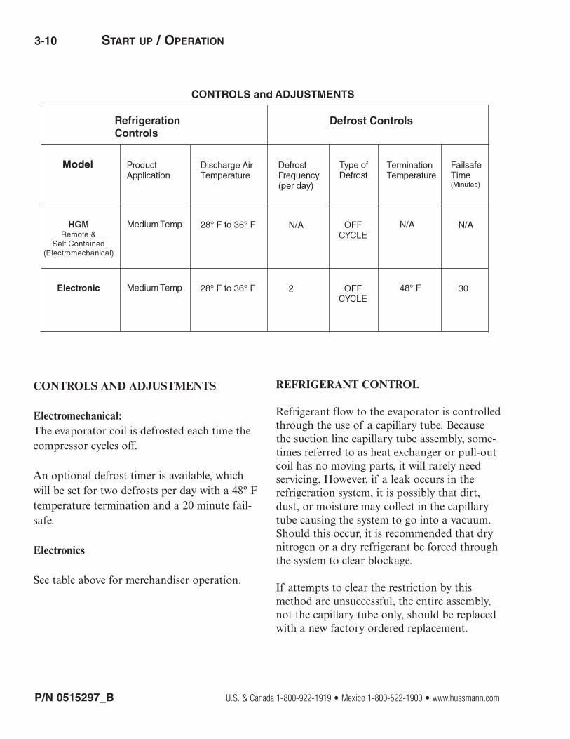
CONTROLS AND ADJUSTMENTS
Electromechanical:The evaporator coil is defrosted each time thecompressor cycles off.
An optional defrost timer is available, whichwill be set for two defrosts per day with a 48º Ftemperature termination and a 20 minute fail-safe.
Electronics
See table above for merchandiser operation.
REFRIGERANT CONTROL
Refrigerant flow to the evaporator is controlled through the use of a capillary tube. Becausethe suction line capillary tube assembly, some-times referred to as heat exchanger or pull-outcoil has no moving parts, it will rarely need servicing. However, if a leak occurs in therefrigeration system, it is possibly that dirt,dust, or moisture may collect in the capillarytube causing the system to go into a vacuum.Should this occur, it is recommended that drynitrogen or a dry refrigerant be forced throughthe system to clear blockage.
If attempts to clear the restriction by thismethod are unsuccessful, the entire assembly,not the capillary tube only, should be replacedwith a new factory ordered replacement.

P/N 0515297_B 3-11
HUSSMANN CORPORATION • BRIDGETON, MO 63044-2483 U.S.A. HGM Merchandisers
LOAD LIMITS
Each merchandiser has a load limit decal. Shelflife of perishables will be short if load limit is violated.
AT NO TIME SHOULD MERCHANDISERS BE
STOCKED BEYOND THE LOAD LIMITS INDICATED.
STOCKING
Product should NOT be placed inside the merchandisers until merchandisers are at proper operating temperature.
Allow merchandiser 24 hours to operate beforeloading product.
Proper rotation of product during stocking is necessary to prevent product loss. Always bringthe oldest product to the front and set thenewest to the back.
AIR DISCHARGE AND RETURN FLUES MUST
REMAIN OPEN AND FREE OF OBSTRUCTION AT
ALL TIMES to provide proper refrigeration andair curtain performance. Do not allow product,packages, signs, etc. to block these grilles. Donot use non-approved shelving, baskets, display racks, or any accessory that couldhamper air curtain performance.
Do not allow product to be placed outside ofthe designated load limits in the illustration.
Do not load product past shelves
27 3/4 (705)
Product Load Limit
Product Load Limit
Product Load Limit
Product Load Limit
Product Load Limit
Product will be degraded and may spoil ifallowed to sit in a non-refrigerated area.

3-12 START UP / OPERATION
P/N 0515297_B U.S. & Canada 1-800-922-1919 • Mexico 1-800-522-1900 • www.hussmann.com
NOTES:

P/N 0515297_B 4-1
HUSSMANN CORPORATION • BRIDGETON, MO 63044-2483 U.S.A. HGM Merchandisers
CARE AND CLEANING
Long life and satisfactory performance of anyequipment is dependent upon the care itreceives. To ensure long life, proper sanitationand minimum maintenance costs, these merchandisers should be thoroughly cleaned,all debris removed and the interiors washeddown, weekly.
Exterior SurfacesThe exterior surfaces must be cleaned with amild detergent and warm water to protect andmaintain their attractive finish. NEVER USE
ABRASIVE CLEANSERS OR SCOURING PADS.
Interior SurfacesThe interior surfaces may be cleaned with mostdomestic detergents, ammonia based cleanersand sanitizing solutions with no harm to thesurface. Self contained models empty into alimited capacity evaporation pan, which willoverflow if excess water is used in cleaning.
Do NOT Use:
•Abrasive cleansers and scouring pads, as thesewill mar the finish.
•Coarse paper towels on coated glass.
•Ammonia-based cleaners on acrylic parts.
•Solvent, oil or acidic based cleaners on any interior surfaces.
•Do not use high pressure water hoses.
Do:
•Remove the product and all loose debris toavoid clogging the waste outlet.
•Store product in a refrigerated area such as a cooler. Remove only as much product as canbe taken to the cooler in a timely manner.
•Disconnect electrical power before cleaning.
•Thoroughly clean all surfaces with soap andhot water. DO NOT USE STEAM OR HIGH WATER
PRESSURE HOSES TO WASH THE INTERIOR. THESE
WILL DESTROY THE MERCHANDISERS’ SEALING
CAUSING LEAKS AND POOR PERFORMANCE.
•Take care to minimize direct contact betweenfan motors and cleaning or rinse water.•Do NOT flood merchandiser with water.NEVER INTRODUCE WATER FASTER THAN THE
WASTE OUTLET CAN REMOVE IT.
SELF CONTAINED MODELS EMPTY INTO A
CONDENSATE EVAPORATION PAN THAT WILL
OVERFLOW IF TOO MUCH WATER IS INTRODUCED
DURING CLEANING.
•Allow merchandisers to dry before resumingoperation.
•After cleaning is completed, turn on power tothe merchandiser.
MAINTENANCE
Product will be degraded and may spoil if allowed to sit in a non-refrigerated area.
Do NOT allow cleaning agent or cloth to contact food product.

4-2 MAINTENANCE
CLEANING STAINLESS STEEL SURFACES
Use non-abrasive cleaning materials, andalways polish with grain of the steel. Use warmwater or add a mild detergent to the water andapply with a cloth. Always wipe rails dry afterwetting.
Use alkaline chlorinated or non-chlorine containing cleaners such as window cleanersand mild detergents. Do not use cleaners containing salts as this may cause pitting andrusting of the stainless steel finish. Do not usebleach.
CLEANING COILS
The condenser can be inspected withoutpulling the whole condensing unit out of thecase. Simply remove the grille on the intakeside of the condensing unit for HGM-BS merchandisers. For HGM-TS, the condensingunit is located at the top of the merchandiser.
Condenser coils should be cleaned at least onceper month. Additional cleaning may be neededdepending on the operational environment. Adirty condenser blocks normal airflow throughthe coils.
Airflow blockage increases energy consumptionand reduces the merchandiser’s ability to main-tain operating temperature.
To clean the coils, use a vacuum cleaner with awand attachment and a soft (non-metallic)brush to remove dirt and debris. Do not bendcoil fins. Always wear gloves and protective eyewear when cleaning near sharp coil fins anddust particles.
Fin Coils
P/N 0515297_B U.S. & Canada 1-800-922-1919 • Mexico 1-800-522-1900 • www.hussmann.com
— LOCK OUT / TAG OUT —To avoid serious injury or death from electricalshock, always disconnect the electrical powerat the main disconnect when servicing orreplacing any electrical component. Thisincludes, but is not limited to, such items asdoors, lights, fans, heaters, and thermostats.
SHUT FANS OFF DURING CLEANING PROCESS.
Do NOT use HOT water on Cold glass Surfaces.This can cause the glass to shatter and could
result in personal injury. Allow glass fronts, towarm before applying hot water.

CLEANING EVAPORATION PAN
The condensate water outlet empties into alimited capacity evaporation pan.
Debris or dirt accumulation inside the condensateevaporation pan or on the heater coil willreduce the pan’s evaporation capacity andcause premature heater failure. The evaporationpan waste water will overflow and spill onto thefloor if the heater is not properly operating.
Always wear protective eye glasses and gloveswhen servicing.
Remove accumulated debris from the evapora-tion pan. Wipe down heater coil with a clothand warm water. Be sure to remove any dirt,debris or liquids from the heater coil.
Water introduced during cleaning will causethe evaporation pan to overflow.
P/N 0515297_B 4-3
HUSSMANN CORPORATION • BRIDGETON, MO 63044-2483 U.S.A. HGM Merchandisers
DO NOT FLOOD!Use only enough water necessary to clean
surface. Water must not drip down the case!
Never use ammonia based cleansers, abrasivecleansers, or scouring pads.
Evaporation Pan is Hot!and poses risk of bodily injury – Always Wear glovesand protective eye wear when servicing. Turn off evaporation pan heater, and allow pan to cool.

4-4 MAINTENANCE
NOTES:
P/N 0515297_B U.S. & Canada 1-800-922-1919 • Mexico 1-800-522-1900 • www.hussmann.com

P/N 0515297_B 5-1
HUSSMANN CORPORATION • BRIDGETON, MO 63044-2483 U.S.A. HGM Merchandisers
REPLACING FAN MOTORS AND BLADES
Should it ever be necessary to service orreplace the fan motors or blades be certainthat the fan blades are replaced correctly.
THE BLADES MUST BE INSTALLED WITH RAISED
EMBOSSING (PART NUMBER ON PLASTIC BLADES)POSITIONED AS INDICATED ON THE PARTS LIST.
For access to these fans:
1. Remove product and place in a refrigeratedarea. Turn off power to the merchandiser.
2. Remove thumb screws that secure thereturn air grille / coil cover.
3. Remove return air grille.
4. Remove fan assembly.
5. Replace fan motor and blade.
6. Reconnect fan to wiring harness.
7. Replace return air grille, and fasten airgrille to coil cover.
8. Turn on power.
9. Verify that motor is working and blade isturning in the correct direction.
REPLACING THERMOMETER
The thermometer may be replaced by removingthe two screws holding it to the evaporator fangrille. Lower the evaporator coil cover byremoving the brass screws located at the twofront corners of the cover. Remove the screwsalong the front edge of the cover holding it tothe grille. Follow the sensing lead to the centerrear of the evaporator coil. Loosen the clipholding it to the bracket, and slide the end ofthe lead out.
Be sure to run the lead of the new thermometerthrough the hole in the fan grille first. Finishassembly in reverse order. The same procedureshould be followed when cleaning the end of thesensing lead.
SERVICE
— LOCK OUT / TAG OUT —To avoid serious injury or death from electricalshock, always disconnect the electrical powerat the main disconnect when servicing orreplacing any electrical component. Thisincludes, but is not limited to, such items asdoors, lights, fans, heaters, and thermostats.
Product will be degraded and may spoil if allowedto sit in a non-refrigerated area.
HGM Fan

5-2 SERVICE
P/N 0515297_B U.S. & Canada 1-800-922-1919 • Mexico 1-800-522-1900 • www.hussmann.com
TROUBLESHOOTING GUIDE
PROBLEM
Compressor runs continuously; product too warm
High head pressure
Warm storage temperature
Compressor runscontinuously; product toocold
Compressor will not start; no noise
Compressor will not start cuts out on overload
PROBABLE CAUSE
1. Short of refrigerant
2. Inefficient compressor3. Dirty condenser
1. Cabinet location too warm2. Restricted condenser air flow
3. Defective condenser fan motor4. Air or non-condensable gasesin system
1. Temperature control notset properly
2. Short of refrigerant
3. Cabinet location too warm4. Too much refrigerant5. Low voltage, compressorcycling on overload
6. Condenser dirty
1. Defective control2. Short on refrigerant
1. Blown fuse or breaker2. Defective or broken wiring3. Defective overload4. Defective temperature control5. Power disconnected
1. Low voltage2. Defective compressor3. Defective relay4. Restriction or moisture5. Inadequate air over condenser
6. Defective condenser fan motor
SOLUTION
1. Leak check, change drier,evacuate and recharge
2. Replace3. Clean
1. Relocate cabinet2. Clean condenser to removeair flow restriction
3. Replace4. Leak check, change drier,evacuate and recharge
1. Reset control.
2. Leak check, replace drierevacuate and recharge
3. Relocate4. Change drier evacuateand recharge
5. Check power6. Clean
1. Replace2. Assure proper length in tube3. Leak check, change drier,evacuate and recharge
1. Replace fuse or reset breaker2. Repair or replace3. Replace4. Replace5. Check service cords or wiring connections
1. Contact electrician2. Replace3. Replace4. Leak check, replace drier, evacuate and recharge
5. Clean condenser6. Replace

APPENDIX A — TECHNICAL DATA A-1
HUSSMANN CORPORATION • BRIDGETON, MO 63044-2483 U.S.A. HGM Merchandisers
Item Part # Description
HGM-1 HGM-2 HGM-3
FAN ASSEMBLIES AND THERMOSTATS
7W Standard Fan AssemblyMO.4410545 Fan Motor, 7 Watt 115V
FB.4780844 HGM-1 / HGM-3 Fan Blade
FB.4780606 HGM-2 Fan Blade
CT.4483087 Safe Net III Controller
CC.4482991 Defrost Sensor (Yellow)
CC.4482992 Air Sensor (Black)
CC.4482540 Safe Net III Display (ºF)
EP.4483064 Safe Net III Harness(Display to Control)
EP.19S216 HGM-1 Power Cord 15 Amp, 115 V
EP.4483064 HGM-2 Power Cord 20 Amp, 115 V
SW.4440542 Power Switch — All models
REFRIGERATION
HGM-1
CU.4200821 Compressor
CO.4671408 Condenser
MO.4411026 Condenser Fan Motor
FB.4780651 Condenser Fan Blade
EV.4671148 Evaporator
RC.4613150 Capillary Tube Assembly
FI.4613665 Filter Drier
Item Part # Description
REFRIGERATION (CONTINUED)
HGM-2
CU.4200822 Compressor
CO.4671499 Condenser
MO.4411026 Condenser Fan Motor
FB.4780850 Condenser Fan Blade
EV.4670394 Evaporator
RC.4613148 Capillary Tube Assembly
FI.4613665 Filter Drier
HGM-3
CU.4200822 Compressor
CO.4671071 Condenser
MO.4411026 Condenser Fan Motor
FB.4780788 Condenser Fan Blade
EV.4670395 Evaporator
FB.4780850 Capillary Tube Assembly
RC.4613486 Filter Drier
DOOR ASSEMBLY (SILVER)
DO.4996562 HGM-1 Door Assembly
DO.4996563 HGM-2 Door Assembly
DO.4996564 HGM-3 Door Assembly
P/N 0515297_B U.S. & Canada 1-800-922-1919 • Mexico 1-800-522-1900 • www.hussmann.com
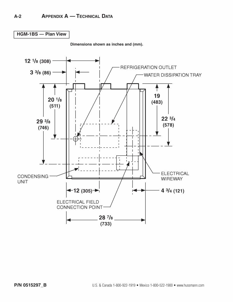
A-2 APPENDIX A — TECHNICAL DATA
HGM-1BS — Plan View
Dimensions shown as inches and (mm).

HUSSMANN CORPORATION • BRIDGETON, MO 63044-2483 U.S.A. HGM Merchandisers
APPENDIX A — TECHNICAL DATA A-3
A
B
C
D
E
F
G
H
ELECTRICAL FIELD CONNECTION POINT
REFRIGERATION OUTLET
CONDENSING UNIT
WATER DISSIPATION TRAY
ELECTRICAL WIREWAY
HGM-2BS & HGM-3BS — Plan View
Dimensions shown as inches and (mm).

P/N 0515297_B U.S. & Canada 1-800-922-1919 • Mexico 1-800-522-1900 • www.hussmann.com
A-4 APPENDIX A — TECHNICAL DATAPreliminary
CONDENSING UNIT
REFRIGERATION OUTLET
7 1/8 (181)
4 1/8 (105) 7 5/8 (194)
28 7/8 (733)
14 3/8 (365)
18 1/2 (470)
18 5/8 (473)
30 5/8 (778)
36 3/8 (924)
25 3/8 (645)
13 1/8 (333)
18 7/8 (479)
ELECTRICAL BOX
DRAIN PAN (LOCATED ON THE BASE)
CONDENSER COIL
HGM-1TS — Plan View
Dimensions shown as inches and (mm).

HUSSMANN CORPORATION • BRIDGETON, MO 63044-2483 U.S.A. HGM Merchandisers
APPENDIX A — TECHNICAL DATA A-5
HGM-2TS — Plan View
Dimensions shown as inches and (mm).

P/N 0515297_B U.S. & Canada 1-800-922-1919 • Mexico 1-800-522-1900 • www.hussmann.com
A-6 APPENDIX A — TECHNICAL DATA
HGM-3TS — Plan View
Dimensions shown as inches and (mm).

HUSSMANN CORPORATION • BRIDGETON, MO 63044-2483 U.S.A. HGM Merchandisers
APPENDIX A — TECHNICAL DATA A-7
HGM — Dimensions
HGM — Electrical Data

P/N 0515297_B U.S. & Canada 1-800-922-1919 • Mexico 1-800-522-1900 • www.hussmann.com
A-8 APPENDIX A — TECHNICAL DATA
HGM-BS — Cross Section
12 1/4 (311)
27 3/4 (705)
34 3/4 (883)
62 3/8 (1584)
82 1/2 (2096)
22 3/4 (578)
EVAPORATOR
DRAIN
CONDENSER UNIT
Dimensions shown as inches and (mm).
REFRIGERATION DATA
HGMThermostatSetting CI/CO (°F)Position #1 39 / 32Position #7 36 / 23
Compressor (hp)HGM-1 1/3HGM-2 1/2HGM-3 3/4
Condensing UnitCapacity(Btu/hr at std. ratingconditions)HGM-1 1870HGM-2 2300HGM-3 4270
(at 10º F evaporator and 110º F condensing temperature)
DEFROST DATA
HGMFrequency (hr) 12
Defrost Termination Temperature 48º F
OFFTIME
Failsafe (min.) 30
PHYSICAL DATA
Refrigerant Charge HGM-1 14.1 oz (0.4) kgHGM-2 40.25 oz (1.14) kgHGM-3 37.75 oz (1.07) kg
Note: This data is based on store temperatureand humidity that does not exceed 75°F and55% R.H. unless otherwise stated. Scheduledefrost at night while lights are off.
HGM-TS — Cross Section

HUSSMANN CORPORATION • BRIDGETON, MO 63044-2483 U.S.A. HGM Merchandisers
APPENDIX A — WIRING DIAGRAM A-9
HGM Remote

P/N 0515297_B U.S. & Canada 1-800-922-1919 • Mexico 1-800-522-1900 • www.hussmann.com
A-10 APPENDIX A — WIRING DIAGRAM
HGM Self Contained

®
To obtain warranty information or other support, contact your
Hussmann representative. Please include the model and serial number of the product.
Hussmann Corporation, Corporate Headquarters: Bridgeton, Missouri, U.S.A. 63044-2483 01 September 2011

Hussmann Corporation12999 St. Charles Rock RoadBridgeton, MO 63044
www.hussmann.com