Embed Size (px)
Citation preview

EXCELLENCE BY DESIGN
INSTALLATIONGUIDE
S O L A R H O T W A T E R
COMBINED MANUALHFLO SYSTEMSOPEN LOOP SYSTEMS:• AC PUMP AND CONTROLLER• DC PUMP, CONTROLLER AND 20 WATT PV MODULE
v2.1

TABLE OF CONTENTS
1. PREPARATIONS 3-9 GOBI INSTALLATION
10-11
2.
12-13
14-16
20
21
17-19
3. HFLO INSTALLATION
4. PIPING
5. COMMISSIONING
6. O & M
NOTES 3
1. PREPARATIONS1.0.0. Safety Guidelines Carefully review all instructions in this manual for installation and use. Do not modify Gobi Collectors or Helio-Pak under any circumstances; use only as designed. This manual and its content are integral parts of both the Helio-Pak and Gobi Solar Collector warranties. Noncompliance with these guidelines will void all warranties.
Follow all local building codes and regulations, as well as these industry accepted guidelines and standards:
IAPMO USEC, UBC, UPCASHRAE Solar Energy EquipmentNFPA 70 National Electric CodeASCE 7-05 Minimum Design Loads for Buildings and Other Structures
Select an installation location that is easily accessible for maintenance and servicing
1.0. General Notes
1.0.1. Collector Storage and HandlingKeep collectors covered when storing.
Avoid lifting collectors by the headers. Take care not to scratch the tempered solar glass; follow the glass breakage guidelines at the end of this manual in case of breakage.
Gobi collectors nest and lock into each other for horizontal transportation. Do not transport Gobi upside down or standing on a side.
1.0.2. Collector InstallationMake a site visit prior to installation to verify adequate installation conditions:
• Collector sun exposure, especially during crucial solar hours of 10AM – 2PM. Take into consideration deciduous tree shading, structures, chimneys, etc.
• Use a minimum tilt of 10° in mild areas and 30° in areas with snow.• Orient collectors within 20° of true South (in North latitudes); use internet maps
rather than compass readings for verification.• Ideal collector tilt for hot water production is equal to site latitude. For space
heating combination systems, use tilt equal to latitude plus 15°. Heliodyne recommends a standard of 35° for hot water and 45° for space heating, regardless of location. Use racks only when necessary, as variation up to 15° can have only small effects on performance.
• Avoid banking of snow and ice below or on the collectors.• Never mount Gobi collectors horizontally in a drainback system.• Heliodyne recommends 6-12” of flex tubing before any rigid copper lines to allow
for thermal expansion in the copper tubing.
1.0.3. Minimum Heat StorageA minimum of 1.5 – 2.0 gallons of liquid heat storage per square foot of Gobi collector (e.g., 60 – 80 gallons per Gobi 410) is recommended.
Minimize stagnation (no load, no flow) conditions on peak output days by using appropriate system sizing and maximizing year round usage. For design assistance, contact Heliodyne.
Ensure the backup heating capacity is properly sized to produce hot water for installation site on days of little or no solar energy production. Use only ASHRAE 90.2 compliant storage tanks and heaters with R-16 or higher.
1.0.4. Equipment for InstallationFor a complete and functional SHW system, ensure the following equipment is ready for installation at the job site:
• Gobi Solar Collectors• Rack or Flush mount hardware kit• Appropriate roof penetration hardware and sealant• Copper tubing, type M or L for collector / heat transfer appliance connections,
adapters, elbows and fittings.• 96/4 Tin/Silver solder• Non-rubber based insulation (Armaflex); 1/2” wall / R2.6l minimum• UV resistant covering or coating for outdoor exposed insulation• Helio-Pak heat transfer appliance (HPAK)• Isolation valves, tempering valve, air vent • Storage tank with adequate volume for collectors installed• Connections for storage tank (flexible or otherwise)• Dyn-O-Flo HD high temperature propylene glycol or equal• Pipe hangers or supports installed per code requirement installed without
compromising any insulation.
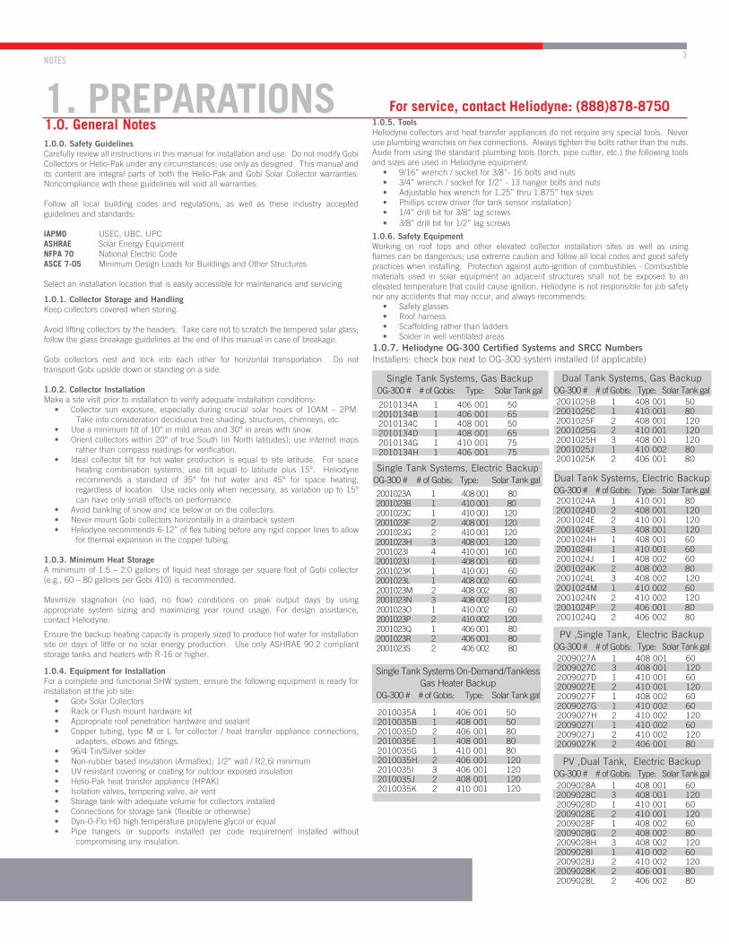
For service, contact Heliodyne: (888)878-87501.0.5. ToolsHeliodyne collectors and heat transfer appliances do not require any special tools. Never use plumbing wrenches on hex connections. Always tighten the bolts rather than the nuts. Aside from using the standard plumbing tools (torch, pipe cutter, etc.) the following tools and sizes are used in Heliodyne equipment:
• 9/16” wrench / socket for 3/8”- 16 bolts and nuts• 3/4” wrench / socket for 1/2” - 13 hanger bolts and nuts• Adjustable hex wrench for 1.25” thru 1.875” hex sizes• Phillips screw driver (for tank sensor installation)• 1/4” drill bit for 3/8” lag screws• 3/8” drill bit for 1/2” lag screws
1.0.6. Safety EquipmentWorking on roof tops and other elevated collector installation sites as well as using flames can be dangerous; use extreme caution and follow all local codes and good safety practices when installing. Protection against auto-ignition of combustibles - Combustible materials used in solar equipment an adjacent structures shall not be exposed to an elevated temperature that could cause ignition. Heliodyne is not responsible for job safety nor any accidents that may occur, and always recommends:
• Safety glasses • Roof harness • Scaffolding rather than ladders• Solder in well ventilated areas
1.0.7. Heliodyne OG-300 Certified Systems and SRCC NumbersInstallers: check box next to OG-300 system installed (if applicable)
2010134A 1 406 001 502010134B 1 406 001 652010134C 1 408 001 502010134D 1 408 001 652010134G 1 410 001 752010134H 1 406 001 75
Single Tank Systems, Gas BackupOG-300 # # of Gobis: Type: Solar Tank gal
Single Tank Systems, Electric Backup OG-300 # # of Gobis: Type: Solar Tank gal
2001023A 1 408 001 802001023B 1 410 001 802001023C 1 410 001 1202001023F 2 408 001 1202001023G 2 410 001 1202001023H 3 408 001 1202001023I 4 410 001 1602001023J 1 408 001 602001023K 1 410 001 602001023L 1 408 002 602001023M 2 408 002 802001023N 3 408 002 1202001023O 1 410 002 602001023P 2 410 002 1202001023Q 1 406 001 802001023R 2 406 001 802001023S 2 406 002 80
Single Tank Systems On-Demand/Tankless Gas Heater Backup
OG-300 # # of Gobis: Type: Solar Tank gal
2010035A 1 406 001 502010035B 1 408 001 502010035D 2 406 001 802010035E 1 408 001 802010035G 1 410 001 802010035H 2 406 001 1202010035I 3 406 001 1202010035J 2 408 001 1202010035K 2 410 001 120
Dual Tank Systems, Gas BackupOG-300 # # of Gobis: Type: Solar Tank gal2001025B 1 408 001 502001025C 1 410 001 802001025F 2 408 001 1202001025G 2 410 001 1202001025H 3 408 001 1202001025J 1 410 002 802001025K 2 406 001 80
Dual Tank Systems, Electric BackupOG-300 # # of Gobis: Type: Solar Tank gal2001024A 1 410 001 802001024D 2 408 001 1202001024E 2 410 001 1202001024F 3 408 001 1202001024H 1 408 001 602001024I 1 410 001 602001024J 1 408 002 602001024K 2 408 002 802001024L 3 408 002 1202001024M 1 410 002 602001024N 2 410 002 1202001024P 2 406 001 802001024Q 2 406 002 80
PV ,Single Tank, Electric BackupOG-300 # # of Gobis: Type: Solar Tank gal2009027A 1 408 001 602009027C 3 408 001 1202009027D 1 410 001 602009027E 2 410 001 1202009027F 1 408 002 602009027G 1 410 002 602009027H 2 410 002 1202009027I 1 410 002 602009027J 2 410 002 1202009027K 2 406 001 80
PV ,Dual Tank, Electric BackupOG-300 # # of Gobis: Type: Solar Tank gal2009028A 1 408 001 602009028C 3 408 001 1202009028D 1 410 001 602009028E 2 410 001 1202009028F 1 408 002 602009028G 2 408 002 802009028H 3 408 002 1202009028I 1 410 002 602009028J 2 410 002 1202009028K 2 406 001 802009028L 2 406 002 80

COLLECTOR SPECIFICATIONS
1.2. Flow and Pressure Loss1
PRESSURE DROP PLOT
1. Losses calculated at recommended Gobi design flow rates for 50/50 propylene glycol / water solution.2. Minimum flow rates shown. Do not exceed recommended flow rates by more than (3) times.
60
70
50
30
40
10
20
0
10
1 2 3 4 5 6 7 8
Number of Gobi in Array (8 Max)
DP
(In
ches
H20
)
10
10
20
30
40
50
60
70
2 3 4 5 6 7 8
Gobi 410
Gobi 408
Gobi 406
RECOMMENDED DESIGN FLOW RATES WITH WATER2
GOBI 406 GOBI 408 GOBI 410
0.67 Gal / min 0.81 Gal / min 1.0 Gal / min
1.1. Technical Specifications for Gobi
DIM DESCRIPTION UNITS GOBI 406 GOBI 408 GOBI 410
L Length
inch
81.56 97.56 121.56
W Width 47.56
T Thickness 2.75
H Header Length 76.88 92.88 116.88
M Header Width 50.25
AAperture Length 79.25 95.25 119.25
Aperture Width 45.25
PPlate Length 78.0 94.0 118.0
Plate Width 46.25
D Flashing Base 0.61
F Flashing Header 1.93
L x W Gross Area ft2 26.94 32.22 40.15
AL x AW Net Area ft2 24.90 29.93 37.47
g Dry Weight lb. 74 102 127
G Full Weight lb. 80 108 135
V Volume Gal. 0.6 0.7 0.8
- Max Pressure PSI 150 (10 Bar)
- Test Pressure PSI 300 (20 Bar)
- Stag. Temp. °F 397.6 (203 °C)
A
D
H
L
P
F
W
M
T
COLLECTOR ORIENTATION AND PLUMBING 5
S O L A R H O T W A T E R
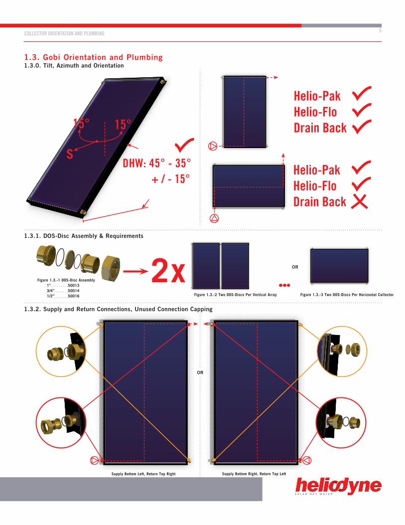
1.3. Gobi Orientation and Plumbing
OR
OR
Figure 1.3.-2 Two DOS-Discs Per Vertical Array
Supply Bottom Left, Return Top Right Supply Bottom Right, Return Top Left
Figure 1.3.-3 Two DOS-Discs Per Horizontal Collector
Figure 1.3.-1 DOS-Disc Assembly 1” 50013 3/4” 50014 1/2” 50016
S
15° 15°
+ / - 15°
Helio-PakHelio-FloDrain Back
Helio-PakHelio-FloDrain Back
DHW: 45° - 35°
2x
1.3.0. Tilt, Azimuth and Orientation
1.3.1. DOS-Disc Assembly & Requirements
1.3.2. Supply and Return Connections, Unused Connection Capping
24
*Op
tion
*AC Version Shown
2
3
14 13
13
5
11
12
25 26
1b
15
47
1a
4
6158
6259
6360
65
64
9
20 21
8
HFLO SPECIFICATIONS
S O L A R H O T W A T E R
S O L A R H O T W A T E R
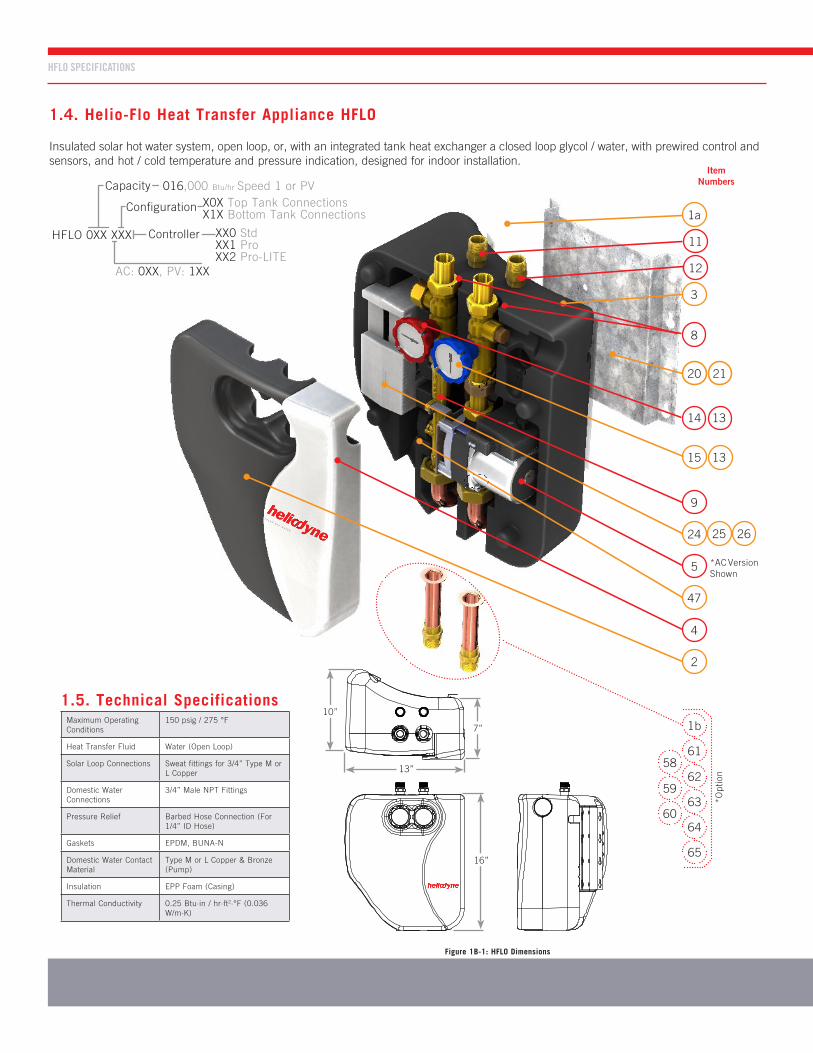
1.4. Helio-Flo Heat Transfer Appliance HFLO
Insulated solar hot water system, open loop, or, with an integrated tank heat exchanger a closed loop glycol / water, with prewired control and sensors, and hot / cold temperature and pressure indication, designed for indoor installation.
10”
7”
16”
13”
Figure 1B-1: HFLO Dimensions
HFLO 0XX XXX
Capacity
XX0 StdXX1 ProXX2 Pro-LITE
X0X Top Tank ConnectionsX1X Bottom Tank Connections
016,000 Btu/hr Speed 1 or PV
Controller
AC: 0XX, PV: 1XX
Configuration
1.5. Technical SpecificationsMaximum Operating Conditions
150 psig / 275 °F
Heat Transfer Fluid Water (Open Loop)
Solar Loop Connections Sweat fittings for 3/4” Type M or L Copper
Domestic Water Connections
3/4” Male NPT Fittings
Pressure Relief Barbed Hose Connection (For 1/4” ID Hose)
Gaskets EPDM, BUNA-N
Domestic Water Contact Material
Type M or L Copper & Bronze (Pump)
Insulation EPP Foam (Casing)
Thermal Conductivity 0.25 Btu·in / hr·ft2·°F (0.036 W/m·K)
Item Numbers

HFLO SPARE PARTS LIST 7
S O L A R H O T W A T E R
1.6. HFLO Replacement Parts1.6.0. HFLO Spare Parts Table (To purchase contact Heliodyne)
ITEM CODE PART NUMBER DESCRIPTION QUANTITY
1aHFLO 016 000HFLO 016 001HFLO 016 100
500835008450131
HFLO heat transfer appliance with built in heat trap and top tank connections
1bHFLO 016 010HFLO 016 011HFLO 016 110
501165011750132
HFLO heat transfer appliance with bottom tank connections
2 HFLO Foam Front 21435 Front insulation casing 1
3 HFLO Foam Back 21436 Back insulation casing 1
4 Acrylic Cover 21442 Front white acrylic cover with logo 1
5AC: UPS 15-58 CiL2PV: Laing DC-5
2309823103
Composite volute circulation pump, 3-speed20 Watt Photovoltaic driven pump
1
8 Solar Connections 21438DOS flange combo valve to 3/4” MIP fitting connections to Solar Collectors
2
9 HFLO 2-40FloCast 21423Bronze flow casting, with flow meter input(plug with clip and O-rings for non Pro models)
1
11 DHW tank: Hot 21729 3/4” NPT fitting hot water out to storage tank 1
12 DHW tank: Cold 21743 3/4” NPT fitting cold water in from storage tank 1
13 Combo Gasket 21186 EPDM gasket for combo valves 3
14 Combo Valve: Hot 23090 Hot combination valve: check, ball, temperature 1
15 Combo Valve: Cold 23091 Cold combination valve: check, ball, temperature 1
20 HFLO Bracket 21204 HFLO Bracket 1
21 X Mount 21453 Tank / Wall Mounting Bracket
22 Mtg Screws 21194 1/4 - 20 x 1” Self-tapping screws for tank mount 4
24 Elec. Box - bot 21198 HFLO / HPAK electrical box - bottom 1
25 Elec. Box - top 21197 HFLO / HPAK electrical box - top 1
26 Delta- T2115321270
Delta - T Control Board, (Standard on PV versions)Delta - T Pro Control Board, Pro or Pro-LITE models only
1
29 SENS 000 001 23029 10,000 Ohm Thermistor Sensors 2
47 Grundfos VFS 2-40 23086Grundfos vortex flow and temperature sensor, Pro and Pro-LITE models only
1
Optional Equipment (Not Included in HFLO Package)
58 Combo Valve: Fill 23092 Filling valve with 1” NPSM M / F connections without gasket -
61 ZZZZ 000 003 23020 Tempering valve, 3/4” sweat 1
62 ZZZZ 000 008 23021 Air vent kit for filling, 1/2” Male NPT 1
63 SENS 000 002 23025 Sensor wire -
64 ZZZZ 000 005 23023 Tank bypass valve 1
65 DOS Tank Dielectric 50016 Brass DOS tank dielectric union with O-ring, 1”C x 3/4” NPT 1 / Nipple
HFLO SYSTEM COMPONENTS OVERVIEW
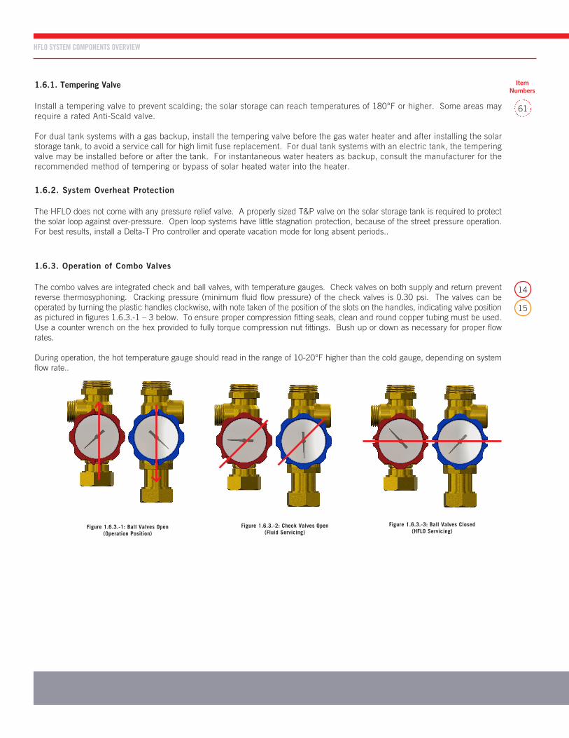
1.6.3. Operation of Combo Valves
The combo valves are integrated check and ball valves, with temperature gauges. Check valves on both supply and return prevent reverse thermosyphoning. Cracking pressure (minimum fluid flow pressure) of the check valves is 0.30 psi. The valves can be operated by turning the plastic handles clockwise, with note taken of the position of the slots on the handles, indicating valve position as pictured in figures 1.6.3.-1 – 3 below. To ensure proper compression fitting seals, clean and round copper tubing must be used. Use a counter wrench on the hex provided to fully torque compression nut fittings. Bush up or down as necessary for proper flow rates.
During operation, the hot temperature gauge should read in the range of 10-20°F higher than the cold gauge, depending on system flow rate..
1.6.1. Tempering Valve
Install a tempering valve to prevent scalding; the solar storage can reach temperatures of 180°F or higher. Some areas may require a rated Anti-Scald valve.
For dual tank systems with a gas backup, install the tempering valve before the gas water heater and after installing the solar storage tank, to avoid a service call for high limit fuse replacement. For dual tank systems with an electric tank, the tempering valve may be installed before or after the tank. For instantaneous water heaters as backup, consult the manufacturer for the recommended method of tempering or bypass of solar heated water into the heater.
1.6.2. System Overheat Protection
The HFLO does not come with any pressure relief valve. A properly sized T&P valve on the solar storage tank is required to protect the solar loop against over-pressure. Open loop systems have little stagnation protection, because of the street pressure operation. For best results, install a Delta-T Pro controller and operate vacation mode for long absent periods..
14
15
61
Figure 1.6.3.-1: Ball Valves Open(Operation Position)
Figure 1.6.3.-2: Check Valves Open(Fluid Servicing)
Figure 1.6.3.-3: Ball Valves Closed(HFLO Servicing)
Item Numbers
16
18
6
8
10
12
14
0
2
4
0 2 4 6 8 10 12 14
40
50
60
70
80
40
0 2 4 6 8 10 12 14
16
18
6
8
10
12
14
0
2
4
0 2 4 6 8 10 12 14
40
50
60
70
80
40
0 2 4 6 8 10 12 14
HFLO SYSTEM COMPONENTS OVERVIEW 9
S O L A R H O T W A T E R
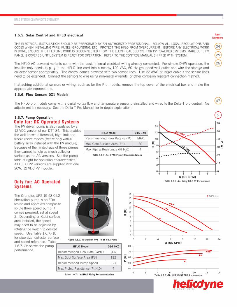
Only for: AC Operated Systems
The Grundfos UPS 15-58 CiL2 circulation pump is an FDA tested and approved composite volute three speed pump; it comes prewired, set at speed 2. Depending on Gobi surface area installed, the speed may need to be adjusted by rotating the switch to desired speed. Use Table 1.6.7.-1b for pipe size, collector surface and speed reference. Table 1.6.7.-2b shows the pump performance.
1.6.7. Pump Operation
The PV driven pump is also regulated by a 12 VDC version of our DTT-84. This enables the well known differential, high limit and freeze recirc modes (freeze only with a battery array installed with the PV module). Because of the limited size of these pumps, they cannot handle as much collector surface as the AC versions. See the pump table at right for operation characteristics. All HFLO PV versions are supplied with one 20W, 12 VDC PV module.
1.6.5. Solar Control and HFLO electrical
THE ELECTRICAL INSTALLATION SHOULD BE PERFORMED BY AN AUTHORIZED PROFESSIONAL. FOLLOW ALL LOCAL REGULATIONS AND CODES WHEN INSTALLING WIRE, FUSES, GROUNDING, ETC. PROTECT THE HFLO FROM OVERCURRENT. BEFORE ANY ELECTRICAL WORK IS DONE, ENSURE THE HFLO LINE CORD IS DISCONNECTED FROM THE ELECTRICAL SOURCE. FOR PV POWERED SYSTEMS, MAKE SURE PV PANEL IS COVERED UNTIL SYSTEM IS READY FOR OPERATION. REFER TO THE CONTROL MANUAL SHIPPED WITH SYSTEM.
The HFLO AC powered variants come with the basic internal electrical wiring already completed. For simple DHW operation, the installer only needs to plug in the HFLO line cord into a nearby 120 VAC, 60 Hz grounded wall outlet and wire the storage and collector sensor appropriately. The control comes prewired with two sensor lines. Use 22 AWG or larger cable if the sensor lines need to be extended. Connect the sensors to wire using non-metal wirenuts, or other corrosion resistant connection method.
If attaching additional sensors or wiring, such as for the Pro models, remove the top cover of the electrical box and make the appropriate connections.
1.6.6. Flow Sensor: 0X1 Models
The HFLO pro models come with a digital vortex flow and temperature sensor preinstalled and wired to the Delta-T pro control. No adjustment is necessary. See the Delta-T Pro Manual for in-depth explanation.
25
26
24
5
47
Figure 1.6.7.-1: Grundfos UPS 15-58 CiL2 Pump
Table 1.6.7.-1b: HPAK Piping Recommendations
Table 1.6.7.-1a: HPAK Piping Recommendations
Table 1.6.7.-2b: UPS 15-58 CiL2 Performance
Table 1.6.7.-2a: Laing DC-5 BT Performance
HFLO Model 016 0XX
Recommended Flow Rate (GPM) 3-6
Max Gobi Surface Area (Ft2) 192
Recommended Pump Speed 1-3
Max Piping Resistance (Ft H20) 4
HFLO Model 016 1X0
Recommended Flow Rate (GPM) MAX
Max Gobi Surface Area (Ft2) 80
Max Piping Resistance (Ft H20) 4
Item Numbers
Q [US GPM]
SPEED
H [
ft]
P [
W]
Q [US GPM]
12 VDC
24 VDC
H [
ft] P
[W]
0 700
14
12
10
8
6
4
2
60
50
40
30
20
10
654321
Only for: DC Operated Systems

HFLO INSTALLATION INSTRUCTIONS
3. HELIO-FLO INSTALLATION3.0. Helio-Flo Connections and Hydraulic Schematic
DHW Out (To Tank)
DHW Out (To Tank)
DHW In (From Tank)
DHW In (From Tank)
From Tank
From Gobi
To Gobi
To Tank
From Gobi
To Tank
From Tank
To Gobi
HFLO (NOV 2011 - CURRENT) with Electric TankHFLO, Helio-Tank 119, Electric Resistance Element Backup
DATE11 / 17 / 11
DOC NO.000038
BYN CUSICK
DESCRIPTION
AIR VENT
P & T RELIEF VALVE
DRAIN VALVE
TEMPERING VALVE
VALVE
SYMBOL
HELIO-FLO SERIES PUMP
PRESSURE RELIEF VALVE
TEMPERATURE GAUGE
DOLE DRIBBLE VALVE
PRESSURE GAUGE
RTD TEMPERATURE SENSOR
GRUNDFOS DIGITAL RELATIVE PRESSURE SENSOR (RPS)
GRUNDFOS DIGITAL VORTEX FLOW SENSOR (VFS)
12"12"
T1
HFLO
12"
18"
T2
12"
18"
M
T1 COLLECTOR OUTLET
T2 STORAGE TANK BOTTOM
T3 STORAGE TANK TOP (OPTIONAL, PRO MODELS ONLY)
T6 VFS FLOW SENSOR TEMP (PRO MODELS ONLY)
PUMP DIFFERENTIAL LOGIC SETUP:
ON: T1 - T2 > 9 F
OFF: T1 - T2 < 4 F
BTU METERING LOGIC SETUP:
“HOT” BTU SENOR = T1
“COLD” BTU SENSOR = T2
“FLOW” BTU SENSOR = GRUNDFS VFS
T3
T6
VFS
M
T
P
P
M
M
T T
Figure 3.0.-1: HFLO Connections
Figure 3.0.-2: HFLO Bottom Mount Hydraulic
Standard
OPTION - Bottom Mount
HFLO 016 X1X
Solar Out (To Gobi)
Solar In (From Gobi)
Solar In (From Gobi) Solar Out (To Gobi)

HFLO INSTALLATION INSTRUCTIONS 11
S O L A R H O T W A T E R
T&P
T&P
DRAIN
SHWM
LONGDIPTUBE
LONGDIPTUBE
SHORTDIPTUBE
SHORTDIPTUBE
Helio-Tank 119
Helio-Tank 119
Tank Interconnect
CTOR 000 000
Helio-Tank 119
Standard Solar 119
Helio-Tank 80
DRAIN
S O L A R H O T W A T E R
Figure 3.1.-1: HFLO Top Mount and Helio-Tank 119 Connections Figure 3.1.-2: HFLO Top Mount and Helio-Tank 80 Connections
Figure 3.2.-1: HFLO with Multiple Helio-Tank 119 Figure 3.2.-2: HFLO with Multiple Standard Solar Tanks
3.1. Tank Orientation
The HFLO is manufactured for installation off center, so the left edge aligns with the side of the tank, rather than each of the center lines matching up. If using a Helio-Tank for installation, orient the proper solar connections near the HFLO connections to reduce piping. On all tanks: ensure proper dip tube length by inspection.
3.2. Plumbing Multiple Tanks
If using multiple tanks to achieve proper storage ratio, always use reverse return plumbing with the cold lines the longest, to ensure least heat loss, and that each tank gets the same amount of circulation. For Helio-Tanks, use the 119 and connect all 2” side ports for increased layering and higher performance.

HFLO INSTALLATION INSTRUCTIONS
Figure 3.5.-1: HFLO Tank Mounting
S O L A R H O T W A T E R
3.5. Helio-Flo Tank Mounting
Use the self-tapping screws provided with the HFLO to mount the X-Bracket to the storage tank (or wall nearby) as shown in figure 3.5-1, then hang the HFLO on the studs of the X-Bracket. Use a level for straightness; the studs in the X-Bracket should be approximately two inches below the top of the tank, to align with the top of the HFLO foam.
3.6. Only for DC Operated Systems -Helio-Flo PV Module Mounting
For PV powered systems, the module needs to be mounted on the collector array. Refer to the installation instructions included with the PV Module Mounting Kit.
Always keep the panel covered until the system is ready for operation. Connect the PV module wiring to the connections extended from the controller box. Take care to preserve polarity.
3.4.0. Storage Sensor Panel Removal and Installation 3.4.1. CollectorSensor Installation
Collector Sensor
3.4. Sensor Installation
HFLO’s come with the necessary sensors pre-wired into the control; for more information see the separate control manual. The controls require at least one tank sensor: on the bottom of the storage tank; the top tank sensor is optional. Most solar storage tanks have a stud near the bottom for placement; the Helio-Tanks have studs for both top and bottom. If a specific area is not available, attach to a metal drain, disconnected lower element, or use the cold in for lower tank sensor; use the hot out for a top tank sensor. The collector sensor must go on the outlet header of the array. For Pro models: the energy production is default set to calculate via the collector outlet sensor and the pre-installed flow meter temperature and flow sensor. For greater accuracy in integrated tank systems, install an additional thermistor sensor just above the inlet to the heat exchanger and connect to T4 at the Delta-T Pro. Consult controller manual for recommended sensor positions.
2”
HFLO PV Junction Box
+ (HOT)
- (GROUND)
PV Module
HFLO (NOV 2011 - CURRENT) with Electric TankHFLO, Helio-Tank 119, Electric Resistance Element Backup
DATE11 / 17 / 11
DOC NO.000038
BYN CUSICK
DESCRIPTION
AIR VENT
P & T RELIEF VALVE
DRAIN VALVE
TEMPERING VALVE
VALVE
SYMBOL
HELIO-FLO SERIES PUMP
PRESSURE RELIEF VALVE
TEMPERATURE GAUGE
DOLE DRIBBLE VALVE
PRESSURE GAUGE
RTD TEMPERATURE SENSOR
GRUNDFOS DIGITAL RELATIVE PRESSURE SENSOR (RPS)
GRUNDFOS DIGITAL VORTEX FLOW SENSOR (VFS)
12"12"
T1
HFLO
12"
18"
T2
12"
18"
M
T1 COLLECTOR OUTLET
T2 STORAGE TANK BOTTOM
T3 STORAGE TANK TOP (OPTIONAL, PRO MODELS ONLY)
T6 VFS FLOW SENSOR TEMP (PRO MODELS ONLY)
PUMP DIFFERENTIAL LOGIC SETUP:
ON: T1 - T2 > 9 F
OFF: T1 - T2 < 4 F
BTU METERING LOGIC SETUP:
“HOT” BTU SENOR = T1
“COLD” BTU SENSOR = T2
“FLOW” BTU SENSOR = GRUNDFS VFS
T3
T6
VFS
M
T
P
P
M
M
T T
PLUMBING THE HFLO
4. PIPING
13
S O L A R H O T W A T E R
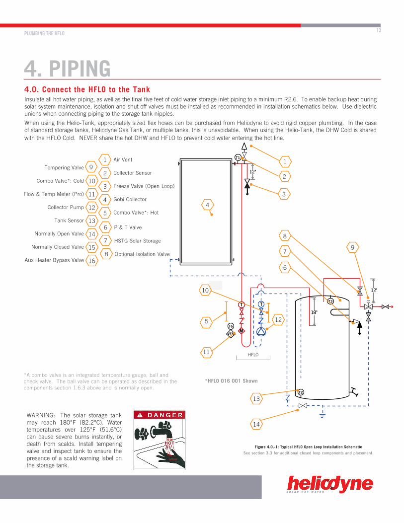
4.0. Connect the HFLO to the TankInsulate all hot water piping, as well as the final five feet of cold water storage inlet piping to a minimum R2.6. To enable backup heat during solar system maintenance, isolation and shut off valves must be installed as recommended in installation schematics below. Use dielectric unions when connecting piping to the storage tank nipples.
When using the Helio-Tank, appropriately sized flex hoses can be purchased from Heliodyne to avoid rigid copper plumbing. In the case of standard storage tanks, Heliodyne Gas Tank, or multiple tanks, this is unavoidable. When using the Helio-Tank, the DHW Cold is shared with the HFLO Cold. NEVER share the hot DHW and HFLO to prevent cold water entering the hot line.
Figure 4.0.-1: Typical HFLO Open Loop Installation Schematic
*HFLO 016 001 Shown
See section 3.3 for additional closed loop components and placement.
1
210
614
4
512
16
311
715
13
9
8
10
5
11
12
14
7
6
13
8
9
4
3
1Air Vent
Tempering ValveCollector Sensor
Freeze Valve (Open Loop)Combo Valve*: Cold
Gobi CollectorFlow & Temp Meter (Pro)
Combo Valve*: HotCollector Pump
Tank SensorP & T Valve
Normally Open ValveHSTG Solar Storage
Normally Closed ValveOptional Isolation Valve
*A combo valve is an integrated temperature gauge, ball and check valve. The ball valve can be operated as described in the components section 1.6.3 above and is normally open.
Aux Heater Bypass Valve
2
WARNING: The solar storage tank may reach 180°F (82.2°C). Water temperatures over 125°F (51.6°C) can cause severe burns instantly, or death from scalds. Install tempering valve and inspect tank to ensure the presence of a scald warning label on the storage tank.

12"
T T P
M
HPAK
Solar Water Heating with Instantaneous HeaterHPAK, Helio-Tank 80, Instantaneous Backup
DATE06 / 18 / 08
DOC NO.000009
BYM STARKEY
M
T1
T3
T5
T4
T2
TOP VIEW
FRONT VIEW
T & P
SEN
SOR
DR
AIN
18"
FLUID PLUMBING SCHEMATIC AND GUIDELINES
S
12"
S
18" 12"
12"
S
18"M
M
M
HFLO
From Solar
Storage
ToSolar
Storage
FromMains
HFLO HFLO
4.2.1. Solar heating with Tankless (Flowthrough) Water Heaters
For systems with Tankless or On-Demand Water Heaters, solar pre-heated water can potentially overheat the internal gas water heater components. For this reason Heliodyne recommends using a Mixing Valve prior to entry into the On-Demand Unit, to mix down the solar heated water to the maximum temperature limit of the gas heater.
Connect the solar storage tank top ports as per tank manual for normal DHW applications
Figure 4.2.-1: Single Standard Tank Figure 4.2.-2: Dual Tank: Electric Backup Figure 4.2.-3: Dual Tank: Gas Backup
Figure 4.2.2-1: Flow Thru Connection
4.2. Additional Tank Schematics
If your tank is not here, contact Heliodyne with questions. Refer to the valve descriptions on the previous page. In accordance with SRCC standard OG-300, all piping and valves must be labeled. Attach the waterproofed labels provided with this manual to the appropriate components using zip-ties.NOTE: For single tank electric systems: disconnect lower element for proper operation.NOTE: For single tank gas systems: tanks with electric pilot and HFLO Pro ONLY
14 1415
16 1415
14 16
S O L A R H O T W A T E R
COLLECTOR FLUID PIPING 15
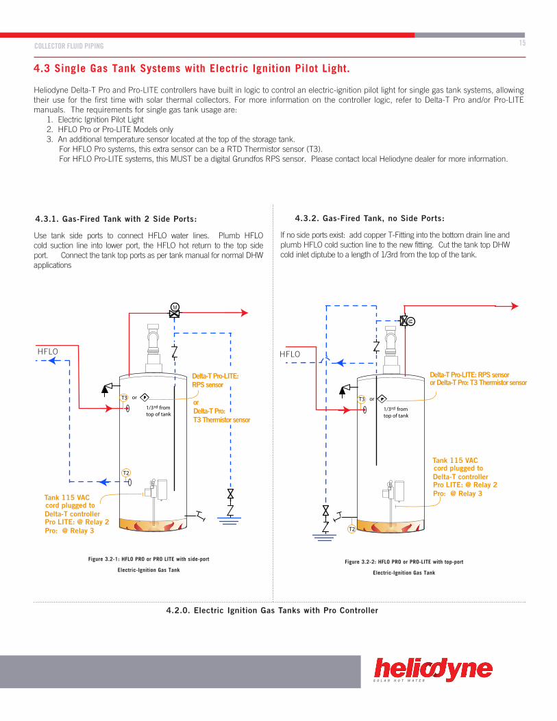
4.3 Single Gas Tank Systems with Electric Ignition Pilot Light.
Heliodyne Delta-T Pro and Pro-LITE controllers have built in logic to control an electric-ignition pilot light for single gas tank systems, allowing their use for the first time with solar thermal collectors. For more information on the controller logic, refer to Delta-T Pro and/or Pro-LITE manuals. The requirements for single gas tank usage are: 1. Electric Ignition Pilot Light 2. HFLO Pro or Pro-LITE Models only 3. An additional temperature sensor located at the top of the storage tank. For HFLO Pro systems, this extra sensor can be a RTD Thermistor sensor (T3). For HFLO Pro-LITE systems, this MUST be a digital Grundfos RPS sensor. Please contact local Heliodyne dealer for more information.
4.3.1. Gas-Fired Tank with 2 Side Ports: 4.3.2. Gas-Fired Tank, no Side Ports:
If no side ports exist: add copper T-Fitting into the bottom drain line and plumb HFLO cold suction line to the new fitting. Cut the tank top DHW cold inlet diptube to a length of 1/3rd from the top of the tank.
Use tank side ports to connect HFLO water lines. Plumb HFLO cold suction line into lower port, the HFLO hot return to the top side port. Connect the tank top ports as per tank manual for normal DHW applications
Figure 3.2-1: HFLO PRO or PRO LITE with side-port
Electric-Ignition Gas TankFigure 3.2-2: HFLO PRO or PRO-LITE with top-port
Electric-Ignition Gas Tank
HFLO HFLO
(T3)
HPAK
T T P
M
T1
DESCRIPTION
AIR VENT
P & T RELIEF VALVE
DRAIN VALVE
TEMPERING VALVE
VALVE
SYMBOL
HELIO-PAK SERIES PUMP
PRESSURE RELIEF VALVE
TEMPERATURE GAUGE
EXPANSION TANK
M
T
PRESSURE GAUGEP
RTD TEMPERATURE SENSOR
PGRUNDFOS DIGITAL RELATIVE PRESSURE SENSOR (RPS)
MGRUNDFOS DIGITAL VORTEX FLOW SENSOR (VFS)
M
Por
1/3 from top of tank
rd
Cold Ground Water In
Hot Water Out
Tank 115 VAC cord plugged to Delta-T controllerPro LITE: @ Relay 2Pro: @ Relay 3
Solar Water Heating with Single Tank Gas
HPAK, Bock Electric Ignition Gas Tank
DATE06 / 18 / 08
DOC NO.000008
BYM STARKEY
T5
T4
Delta-T Pro-LITE: RPS sensor
or Delta-T Pro: T3 Thermistor sensor
T2
T3
DESCRIPTION
AIR VENT
P & T RELIEF VALVE
DRAIN VALVE
TEMPERING VALVE
VALVE
SYMBOL
HELIO-PAK SERIES PUMP
PRESSURE RELIEF VALVE
TEMPERATURE GAUGE
EXPANSION TANK
M
M
Por
(T3)
T
PRESSURE GAUGEP
RTD TEMPERATURE SENSOR
PGRUNDFOS DIGITAL RELATIVE PRESSURE SENSOR (RPS)
MGRUNDFOS DIGITAL VORTEX FLOW SENSOR (VFS)
1/3 from top of tank
rd
HPAK
T T P
M
Cold Ground Water In
Hot Water Out
Tank 115 VAC cord plugged to Delta-T controllerPro LITE: @ Relay 2Pro: @ Relay 3
Solar Water Heating with Single Tank Gas
HPAK, Bock Electric Ignition Gas Tank
DATE06 / 18 / 08
DOC NO.000008
BYM STARKEY
T5
T4
T1
Delta-T Pro-LITE: RPS sensor or Delta-T Pro: T3 Thermistor sensor
T2
T3
4.2.0. Electric Ignition Gas Tanks with Pro Controller

SYSTEM FILL AND STARTUP
5. COMMISSIONING5.0. Clean and Pressure Test the Collector Loop
Before filling the collector loop with potable water, pressure test the collector loop to check for soldering leaks and proper joint mates. For closed loop systems, remove the expansion tank first and cap the connection. Fill the collector loop with water using the site hose and pressurize up to mains pressure; the filling station can also be used. Heliodyne recommends pressure testing up to at least 100 psig. Monitor the pressure gauge for drops in pressure, inspect all joints.
After pressure testing, flush the system with water, or a 1-2% solution of TSP and water. Flushing can be done easiest using the filling valve installed between the collector and HFLO (for either open or closed loop) and a filling station.
5.2. Final Fill and Commissioning5.2.0. Only For: Open Loop System VersionsFilling an open loop system is quite simple. Since the collectors, HFLO, and storage tank are all on the same fluid circuit, it is only necessary to re-open the storage tank supply from mains water, and the system will begin to fill automatically. With the air vent open, the system is able to rid itself of air pockets, though it is good practice to run the circulation pump manually after the system has filled, to assist in bleeding.
After filling, ensure the controller is set to run in freeze protected mode (see accompanying manual for further detail). Plug in the power cord (or uncover the PV module) and set the controller to run in “Auto”.

MAINTENANCE 17
S O L A R H O T W A T E R
6. O&M
MotorBolts
Close Ball Valves: Rotate 90° CW
6.0. Annual Operational Checks and Troubleshooting
Every year the solar system should be checked to ensure optimal performance; these annual checks performed by a qualified professional should not take the place of good operation overview by the systems owner. Annually or more often, the following content should be verified.
All Systems:6.0.0. Check the collector pump for operation
• With proper operation, the hot or red gauge should read 10-20°F hotter than the blue gauge.• With a temperature difference greater than 20°F, set the pump speeds to a higher level. For a difference less than 10°F, set the pump
speeds to a lower level.• Loud operation or squealing means air in the system, follow filling guidelines for re-pressurization.• No temperature difference could mean a pump failure, test pump supply voltage at pump electrical box, listen and feel for OP.• No temperature difference could also mean a diptube wasn’t installed correctly, or at the right length. Review tank schematics in this
manual for proper length. • The hot and cold ball valves could be turned incorrectly; ensure the slots on the top and bottom of the plastic red or blue colored handle
are aligned vertically.• The filling valve bypass could be turned incorrectly; ensure the slot aligns vertically.
6.0.1. Check the control and sensors• Ensure the sensors are giving proper readings by either viewing the software in the Delta-T Pro, or using a multimeter to measure
resistance. See the control manual for further details.• Check wiring to ensure it is undamaged and continuous.
6.0.2. Check pressure gauge• Pressure gauge on HFLO should be no less than 30 psig when system is cold. Follow filling guidelines for re-pressurization.• Inspect system for leaks.
6.1. MaintenanceTo replace parts on the HFLO, close the hot and cold ball valves for servicing equipment underneath them such as pump, heat exchanger, flow sensor, etc, and turn off the water supply to the storage tank. For servicing PRV, pressure gauge, expansion tank or collectors and piping, the system should be drained in the direction of flow via the fill valve. If the fluid is good, drain it to a bucket for reuse. Estimated time per component: 1-2 hours.
To replace any of the combo valves, unscrew appropriate valve, and replace gasket with valve; torque connections to 30 lb-ft. Estimated time: 2 hours.
To service a pump, the motor housing only needs replacing, as volutes have no moving parts. Disconnect electricity from HFLO, then disconnect the pump wiring with the spring clamps. Unscrew the four allen-keyed bolts and replace motor and electrical connections. Torque bolts to 80 lb-in. Estimated time: 2 hours
To service the controller, disconnect the electricity from the unit and remove the box housing, unplug all connections and power wiring, and replace the board. After reinstalling a new controller, test operation by turning the control on manually. Estimated time: 1 hour.
NOTES
7. SYSTEM NOTES 7.0. System Notes
Installation and service should be performed by qualified personnel only.Always follow the most recent version of the Heliodyne Collector Installation and Maintenance Guidelines for collector installation.
7.0.0. System Fluid InformationAlways use copper tubing for collector supply and return connections. Black iron pipe can also be used, with proper dielectrics. Never use galvanized pipe or plastic based products, such as PEX.
Rinse system with 1 – 2% mixture of trisodium phosphate and water. Remove the expansion tank for testing only, and pressure test system with water before filling.
Maintain minimum operating pressure of 30psig when system is cold to avoid pump cavitation. If using an air vent during filling, ensure it is closed during system operation.
7.0.1. Safety PrecautionsFollow all local codes and regulations. All equipment should be grounded for protection against lightening.
It is the installer’s responsibility to ensure all the codes and inspections are carried out and that he or she is fully versed in these guidelines.
Work should only be performed on the HFLO and system when it is disconnected from the power supply.
When creating and repairing roof penetrations, ensure final seal disallows any unwanted animal or creature intrusion, and the integrity of the structure is not compromised. Penetrations through fire-rated assemblies must not reduce fire resistance capacity below code.
7.0.2. ComponentsPlace the HFLO and tank in a non-freezing environment.
Building materials adjacent to solar components must not be exposed to elevated temperatures produced by the solar system.
Solder suitable for 400°F and 150 psig must be used: 96/4 Tin / Silver is recommended.
Use non-plastic pipe insulation, such as Armaflex.
Route the pressure relief port on the HFLO to drain to avoid accidental scalding in case of release.
7.0.3. Description Of Product and OperationThe HFLO is a fully automatic solar energy heat transfer appliance. The controller senses the collector and storage temperatures and powers both circulation pumps when the collector has achieved enough temperature over the solar storage tank. See the Delta-T and Delta-T Pro manuals for full descriptions of operation, functions and warranties.
7.0.4. CommissioningAfter the system is filled, it is normal for the initial pressure to drop as air comes out of solution. Repressurize the system to ensure at least 30 psig when cold. Ensure the control has appropriate freeze protection settings (if applicable) and the tank high limit has been set at a temperature at or below the tank manufacturer’s recommendation.
WARRANTY 19
8. WARRANTY
S O L A R H O T W A T E R
8.0. WarrantyHELIODYNE, shall provide a warranty for defects in compliance with the purchased goods delivered after 3/1/2009 as follows: the HFLO and HFLO Pro product (Products) to be free from defects in material and workmanship, and malfunctions and failure to perform, under normal use and service, for a period of three (3) years from date of installation, provided that said products have been installed in accordance with HELIODYNE’s Installation Instructions. This warranty applies to the first retail buyer and to any subsequent owners.
In the event that evidence cannot be provided to indicate the date of installation, then the period of time shall be thirty six (36) months from the date of manufacture.
Objects are warranted at HELIODYNE’s discretion by repair of the object of purchase or replacement of defective parts, exchange or reduction of price. The right of the contractor to convert objects is ceded by common consent. Replaced parts become the property of HELIODYNE. Wages and costs spent on installation and disassembly must be covered by the client. This provision similarly applies to all warranty agreements. It is at HELIODYNE’s discretion to replace defective goods with similar, faultless goods. In this case, any rights to cancel the agreement cease. The client expressly waives the right for it and its legal successors to assert claims for damages or loss of profit (including without limitation special, indirect, loss of use, contingent, or consequential damages) due to defects or nonconformity in the purchased good. The warranty set forth above constitutes the sole and exclusive remedy against HELIODYNE for the furnishing of any nonconforming or defective goods. THE ABOVE WARRANTY IS EXPRESSLY IN LIEU OF ALL OTHER WARRANTIES, EXPRESS OR IMPLIED, INCLUDING WITHOUT LIMITATION ANY WARRANTY AS TO MERCHANTABILITY OR FITNESS FOR A PARTICULAR USE OR PURPOSE.
If the Product contains a defect that cannot be repaired after a reasonable number of attempts to do so, you, the buyer, may elect either a refund of its purchase price, or a replacement without charge. A replacement may consist of a new or factory rebuilt product of at least the same quality. A new warranty shall apply to any replacement.
Claims on warranty will only be admitted and considered if they are announced in writing immediately after the defect was first noticed. Oral communication or communication by telephone is not sufficient. To obtain service on the Product, notify Heliodyne Customer Service by email at [email protected], by letter to 4910 Seaport Ave., Richmond, CA, 94804. Provide proof of purchase and date.
Should service be requested and no defect found in theProduct, then a reasonable charge will be made for the service.
In no event shall HELIODYNE be liable for the following: • Conditions resulting from a defect in a component or part that
does not make up the HELIODYNE Product. • Conditions resulting from a significant departure from Heliodyne’s
Installation Instructions. • Conditions resulting from any misuse, abuse, negligence, weather
damage, accident or alteration. • Consequential damages such as: damage to your property, loss of
time, inconvenience or loss of use of the Product or any incidental expenses resulting from any breach of the express warranty. Conditions that may occur in the normal operation of the Product shall not be invoked by HELIODYNE to reduce or defeat the coverage of this warranty.
HELIODYNE’s liability under this warranty shall be in lieu of all warranties of fitness and in lieu of all warranties of merchantability. Heliodyne shall not be liable for any incidental or consequential damages covered by a defective product. The maximum liability under this warranty shall not exceed the contract price of the Product. Some states do not allow the exclusion or limitations of incidental or consequential damages, and some states do not allow limitations on implied warranties, such as that of fitness and of merchantability. Therefore the above exclusions and limitations do not apply to you.
The warranty excludes damage caused by force majeure and malfunction that are due to improper assembly, and/or product installation. HELIODYNE is not liable for possible costs resulting from defects. In order for HELIODYNE to accept liability:• Installation must have been carried out by a licensed specialized
company (heating contractor or plumber) following the version of installation instructions in force;
• HELIODYNE or its representative was given the opportunity to check complaints on site immediately after any defect occurred;
• Confirmation exists that the system was commissioned properly and that the system was checked and maintenance was performed annually by a specialized company licensed for this purpose. The warranty agreed by HELIODYNE is only valid for their clients.
This warranty gives you specific legal rights, and you may also have other rights, which vary from state to state. Unless otherwise explicitly agreed in writing, it is understood that these are the only written warranties given by HELIODYNE, and HELIODYNE neither assumes nor authorizes anyone to assume for it any other obligation or liability in connection with the Product.

Heliodyne,Inc.•4910SeaportAvenue•Richmond,CA94804T:510.237.9614•F:510.237.7018
www.heliodyne.comSales Inquiries: [email protected]
Information and Support: [email protected]
20120716