Embed Size (px)
Citation preview
Co
un
ty o
f S
an
D
ieg
o, P
lan
nin
g &
D
evelo
pm
en
t S
ervices
MIN
IM
UM
C
ON
ST
RU
CT
IO
N S
PE
CIF
IC
AT
IO
NS
BU
IL
DIN
G D
IV
IS
IO
N
BUILD
ING
RECO
RD ID
:
OWNE
R OR
CON
TRAC
TOR
SIGNA
TURE
:
THESE ARE MINIMUM REQUIREMENTS ANDSHALL NOT SUPERSEDE MORE RESTRICTIVE
SPECIFICATIONS ON THE PLANS OR ASREQUIRED BY APPLICABLE CODE.
U
B
L
P
T
E
H
I
S
M
O
T
S
L
E
T
V
I
E
D
C
G
O
O
DE
I
G
O
C
C
I
L
S
A
N
C
H
E
N
O
T
D
M
C
NY
I
B
T
O
UO
F
PDS 081 (REV. 01/20/2021)
CS-1
A. General
Applicable codes. All projects shall comply with the 2019 California Building Code (CBC)
and/or California Residential Code (CRC), 2019 California Green Building Standards Code
(CalGreen), 2019 California Electrical Code (CEC), 2019 California Mechanical Code (CMC),
2019 California Plumbing Code (CPC), 2019 California Fire Code (CFC), 2019 California
Building Energy Efficiency Standards (CBEES), and all County of San Diego amendments.
A. Electrical, Plumbing, and Mechanical
1. Exterior lighting. All projects shall comply with the County of San Diego lighting
ordinance.
2. GFCI outlets. Ground Fault Circuit Interrupter (GFCI) outlets are required in bathrooms,
at kitchen countertops, at laundry and wet bar sinks, in garages, in crawlspaces, in
unfinished basements, and outdoors. (CEC 210.8)
3. AFCI outlets. Electrical circuits in bedrooms, living rooms, dining rooms, dens, closets,
hallways, or similar rooms must be protected by Arc Fault Circuit Interrupters (AFCI).
(CEC 210.12)
4. Luminaire requirements. Installed luminaires shall meet the efficacy and fixture
requirements of CBEES 150.0(k).
5. Smoke detectors in building remodels. Smoke detectors are required in each existing
sleeping room, outside each separate sleeping area in the immediate vicinity of sleeping
rooms, and on each story of a dwelling including basements. Battery-operated detectors
are acceptable in existing areas with no construction taking place and in alterations not
resulting in removal of interior wall or ceiling finishes and without access via an attic,
crawl space, or basement. (CRC R314.3)
6. Carbon monoxide detectors in building remodels. Carbon monoxide detectors are
required outside each separate sleeping area in the immediate vicinity of sleeping rooms
and on each story of a dwelling including basements. Battery-operated detectors are
acceptable in existing areas with no construction taking place and in alterations not
resulting in removal of interior wall or ceiling finishes and without access via an attic,
crawl space, or basement. (CRC R315.3)
7. Water heater seismic strapping. Minimum two 3/4-inch-by-24-gauge straps required
around water heaters, with 1/4-inch-by-3-inch lag bolts attached directly to framing.
Straps shall be at points within upper third and lower third of water heater vertical
dimension. Lower connection shall occur minimum 4 inches above controls. (CPC 507.2)
8. Gas appliances in garages. Water heaters and heating/cooling equipment capable of
igniting flammable vapors shall be placed on minimum 18-inch-high platform unless
listing report number provided showing ignition-resistant appliance. (CPC 507.13 and
CMC 305.1)
9. Impact protection of appliances. Water heaters and heating/cooling equipment subject
to vehicular impact shall be protected by bollards or an equivalent measure. (CPC
507.13.1 and CMC 305.11)
10. Water closet clearance. Minimum 30-inch-wide by 24-inch-deep clearance required at
front of water closets. (CPC 402.5)
11. Shower size. Shower compartments shall have minimum area of 1024 square inches
and be able to encompass a 30-inch-diameter circle. Shower doors shall have a
minimum 22-inch unobstructed width. (CPC 408.5 and CPC 408.6)
12. Fireplace appliances. Fireplaces with gas appliances are required to have the flue
damper permanently fixed in the open position and fireplaces with LPG appliances are to
have no 'pit' or 'sump' configurations. (CMC 303.7.1)
13. Chimney clearance. Minimum 2-foot chimney clearance required above building within
10-foot horizontally of chimney. The chimney shall extend minimum 3 feet above highest
point where chimney passes through roof. (CRC R1003.9)
C. Mechanical Ventilation and Indoor Air Quality (ASHRAE 62.2-2010)
1. Transfer air. Ventilation air shall be provided directly from the outdoors and not as
transfer air from adjacent dwelling units or other spaces, such as garages, unconditioned
crawlspaces, or unconditioned attics. (CBEES 150.0(o))
2. Instructions and labeling. Ventilation system controls shall be labeled and the home
owner shall be provided with instructions on how to operate the system. (CBEES
150.0(o))
3. Combustion and solid-fuel burning appliances. Combustion appliances shall be
properly vented and air systems shall be designed to prevent back drafting. (CBEES
150.0(o))
4. Garages. The wall and openings between occupiable spaces and the garage shall be
sealed. HVAC systems that include air handlers or return ducts located in garages shall
have total air leakage of no more than 6% of total fan flow when measured at 0.1 in. w.c.
using California Title 24 or equivalents. (CBEES 150.0(o))
5. Minimum filtration. Mechanical systems supplying air to occupiable space through
ductwork shall be provided with a filter having a minimum efficiency of MERV 6 or better.
(CBEES 150.0(o))
6. Air inlets. Air inlets (not exhaust) shall be located away from known contaminants.
(CBEES 150.0(o))
7. Air moving equipment. Air moving equipment used to meet either the whole-building
ventilation requirement or the local ventilation exhaust requirement shall be rated in
terms of airflow and sound. (CBEES 150.0(o))
a. All continuously operating fans shall be rated at a maximum of 1.0 sone.
b. Intermittently operated whole-building ventilation fans shall be rated at a maximum of
1.0 sone.
c. Intermittently operated local exhaust fans shall be rated at maximum of 3.0 sone.
d. Remotely located air-moving equipment (mounted outside of habitable spaces) need
not meet sound requirements if at least 4 feet of ductwork between fan and intake grill.
D. Foundation and Underfloor
1. Foundation reinforcement. Continuous footings and stem walls shall be provided with a
minimum two longitudinal No. 4 bars, one at the top and one at the bottom of the footing.
(CRC R403.1.3.3)
2. Shear wall foundation support. Shear walls shall be supported by continuous
foundations. (CRC 403.1.2)
3. Concrete slabs-on-grade. Slabs-on-grade shall be minimum 3-1/2-inches thick. (CRC
R506.1)
4. Vapor retarder. A 6-mil polyethylene or approved vapor retarder with joints lapped
minimum 6 inches shall be placed between a concrete slab-on-grade and the base
course or subgrade. (CRC 506.2.3)
5. Anchor bolts and sills. Foundation plates or sills shall be bolted or anchored to the
foundation or foundation wall per the following (CRC R403.1.6 and CRC R602.11.1):
a. Minimum 1/2-inch-diameter steel bolts
b. Bolts embedded at least 7 inches into concrete or masonry
c. Bolts spaced maximum 6 feet on center
d. Minimum two bolts per plate/sill piece with one bolt located maximum 12 inches and
minimum 7 bolt diameters from each end of each sill plate/piece
e. Minimum 3-inch by 3-inch by 0.299-inch steel plate washer between sill and nut on
each bolt
6. Hold-downs. All hold-downs must be tied in place prior to foundation inspection.
7. Protection of wood against decay. Naturally durable or preservative-treated wood shall
be provided in the following locations (CRC R317.1):
a. All wood in contact with ground, embedded in concrete in direct contact with ground, or
embedded in concrete exposed to weather
b. Wood joists within 18 inches and wood girders within 12 inches of the exposed ground
in crawl spaces shall be of naturally durable or preservative-treated wood
c. Wood framing members that rest on concrete or masonry exterior foundation walls and
are less than 8 inches from exposed earth shall be of naturally durable or
preservative-treated wood
d. Wood framing, sheathing, and siding on the exterior of the building and having
clearance less than 6 inches from the exposed ground or less than 2 inches vertically
from concrete steps, porch slabs, patio slabs, and similar horizontal surface exposed to
weather
e. Sills and sleepers on concrete or masonry slab in direct contact with ground unless
separated from such slab by impervious moisture barrier
D. Foundation and Underfloor (Continued)
f. Ends of wood girders entering masonry or concrete walls with clearances less than 1/2
inch on tops, sides, and ends
g. Wood structural members supporting moisture-permeable floors or roofs exposed to
weather, such as concrete or masonry slabs, unless separated from such floors or
roofs by an impervious moisture barrier
h. Wood furring strips or other wood framing members attached directly to interior of
exterior concrete or masonry walls below grade except where vapor retarder applied
between wall and furring strips or framing members
8. Underfloor ventilation. Underfloor areas shall have ventilation openings through
foundation walls or exterior walls, with minimum net area of ventilation openings of 1
square foot for each 150 square feet of underfloor area. On such ventilating opening
shall be within 3 feet of each corner of the building. (CRC R408.1)
9. Underfloor access. Underfloor areas shall be provided with a minimum 18-inch by
24-inch access opening. (CRC R408.4)
E. Wood Framing
1. Fastener requirements. The number, size, and spacing of fasteners connecting wood
members/elements shall not be less than that set forth in CRC Table R602.3(1). (CRC
R502.9, CRC R602.3, and CRC R802.2)
2. Stud size, height, and spacing. The size, height, and spacing of studs shall be in
accordance with CRC Table R602.3(5). (CRC R602.3.1)
3. Sill plate. Studs shall have full bearing on nominal 2-inch thick or larger sill plate with
width at least equal to stud width. (CRC R602.3.4)
4. Bearing studs. Where joists, trusses, or rafters are spaced more than 16 inches on
center and the bearing studs below are spaced 24 inches on center, such members shall
bear within 5 inches of the studs beneath. (CRC R602.3.3)
5. Drilling and notching of studs. Any stud in an exterior wall or bearing partition may be
cut or notched to a depth not exceeding 25% of its width. Studs in nonbearing partitions
may be notched to a depth not to exceed 40% of a single stud width. Any stud may be
bored or drilled, provided the diameter of the resulting hole is no more than 60% of the
stud width, the edge of the hole is no more than 5/8 inch to the edge of the stud, and the
hole is not located in the same section as a cut or notch. Studs located in exterior wall or
bearing partitions drilled over 40% and up to 60% shall also be doubled with no more
than two successive studs bored. (CRC R602.6)
6. Top plate. Wood stud walls shall be capped with a double top plate installed to provide
overlapping at corners and at intersections with other partitions. End joints in double top
plates shall be offset at least 24 inches. Joints in plates need not occur over studs.
Plates shall be minimum nominal 2 inches thick and have width at least equal to width of
studs. (CRC R602.3.2)
7. Top plate splices. Top plate lap splices shall be face-nailed with minimum 8 16d nails
on each side of splice. (CRC R602.10.8.1)
8. Drilling and notching of top plate. When piping or ductwork is placed in or partly in an
exterior wall or interior load-bearing wall, necessitating cutting, drilling, or notching of the
top plate by more than 50% of its width, a galvanized metal tie not less than 0.054-inch
thick and 1-1/2-inches wide shall be fastened across and to the plate at each side of the
opening with not less than 8 10d nails having a minimum length of 1-1/2 inches at each
side or equivalent. The metal tie must extend minimum 6 inches past the opening. (CRC
R602.6.1)
9. Cripple walls. Foundation cripple walls shall be framed of studs not less in size than the
studding above. Cripple walls more than 4 feet in height shall have studs sized as
required for an additional story. Cripple walls with stud height less than 14 inches shall be
sheathed on at least one side with a wood structural panel fastened to both the top and
bottom plates in accordance with Table R602.3(1), or the cripple walls shall be
constructed of solid blocking. Cripple walls shall be supported on continuous
foundations. (CRC R602.9)
10. Wall bracing. Buildings shall be braced in accordance with the methods allowed per
CRC R602.10.2, CRC R602.10.4, and/or CRC R602.10.5.
11. Braced wall line spacing. Spacing between braced wall lines shall not exceed 20 feet
or alternate provisions of CRC R602.10.1.3.
12. Shear wall cumulative length. The cumulative length of shear walls within each braced
wall line shall meet the provisions of CRC Table R602.10.3(1) for wind loads and CRC
Table R602.10.3(2) for seismic loads. (CRC R602.10.1.1)
13. Shear wall spacing. Shear walls shall be located not more than 25 feet on center. (CRC
R602.10.2.2)
14. Shear wall offset. Shear walls may be offset out-of-plan not more than 4 feet from the
designated braced wall line and not more than 8 feet from any other offset wall
considered part of the same braced wall line. (CRC R602.10.1.2)
15. Shear wall location. Shear walls shall be located at the ends of each braced wall line or
meet the alternate provisions of CRC R602.10.2.2.
16. Individual shear wall length. Shear walls shall meet minimum length requirements of
CRC R602.10.6.5.1.
17. Cripple wall bracing. Cripple walls shall be braced per CRC R602.10.11.
18. Shear wall and diaphragm nailing. All shear walls, roof diaphragms, and floor
diaphragms shall be nailed to supporting construction per CRC Table R602.3(1). (CRC
R604.3)
19. Shear wall joints. All vertical joints in shear wall sheathing shall occur over, and be
fastened to, common studs. Horizontal joints in shear walls shall occur over, and be
fastened to, minimum 1-1/2-inch-thick blocking. (CRC R602.10.10)
20. Framing over openings. Headers, double joists, or trusses of adequate size to transfer
loads to vertical members shall be provided over window and door openings in
load-bearing walls and partitions. (CBC 2304.3.2)
21. Joists under bearing partitions. Joists under parallel bearing partitions shall be of
adequate size to support the load. Double joists, sized to adequately support the load,
that are separated to permit the installation of piping or vents shall be full-depth
solid-blocked with minimum 2-inch nominal lumber spaced at maximum 4 feet on center.
Bearing partitions perpendicular to joists shall not be offset from supporting girders,
walls, or partitions more than the joist depth unless such joists are of sufficient size to
carry the additional load. (CRC R502.4)
22. Joists above or below shear walls. Where joists are perpendicular to a shear wall
above or below, a rim joist, band joist, or blocking shall be provided along the entire
length of the shear wall. Where joists are parallel to a shear wall above or below, a rim
joist, end joist, or other parallel framing shall be provided directly above and/or below the
shear wall. Where a parallel framing member cannot be located directly above and/or
below the shear wall, full-depth blocking at 16-inch spacing shall be provided between
the parallel framing members to each side of the shear wall. (CRC R602.10.8)
23. Floor member bearing. The ends of each floor joist, beam, or girder shall have
minimum 1-1/2 inches of bearing on wood or metal and minimum 3 inches of bearing on
masonry or concrete except where supported on a 1-inch-by-4-inch ribbon strip and
nailed to the adjoining stud or by the use of approved joist hangers. (CRC R502.6)
24. Floor joist lap. Floor joists framing opposite sides over a bearing support shall lap
minimum 3 inches and shall be nailed together within minimum 3 10d face nails. A wood
or metal splice with strength equal to or greater than that provided by the lap is permitted.
(CRC R502.6.1)
25. Floor joist-to-girder support. Floor joists framing into the side of a wood girder shall be
supported by approved framing anchors or on ledger strips minimum nominal 2 inches by
2 inches. (CRC R502.6.2)
26. Floor joist lateral restraint. Floor joists shall be supported laterally at ends and each
intermediate support by minimum 2-inch full-depth blocking, by attachment to full-depth
header, band joist, or rim joist, to an adjoining stud, or shall be otherwise provided with
lateral support to prevent rotation. (CRC R502.7)
27. Floor joist bridging. Floor joists exceeding nominal 2 inches by 12 inches shall be
supported laterally by solid blocking, diagonal bridging (wood or metal), or a continuous
1-inch-by-3-inch strip nailed across the bottom of joists perpendicular to joists at
maximum 8-foot intervals. (CRC R502.7.1)
28. Framing of floor openings. Openings in floor framing shall be framed with a header and
trimmer joists. When the header joist span does not exceed 4 feet, the header joist may
be a single member the same size as the floor joist. Single trimmer joists may be used to
carry a single header joist located within 3 feet of the trimmer joist bearing. When the
header joist span exceeds 4 feet, the trimmer joists and header joist shall be doubled and
of sufficient cross section to support the floor joists framing into the header. Approved
hangers shall be used for the header-joist-to-trimmer-joist connections when the header
joist span exceeds 6 feet. Tail joists over 12 feet long shall be supported at the header
by framing anchors or on ledger strips minimum 2 inches by 2 inches. (CRC R502.10)
E. Wood Framing (Continued)
29. Girders. Girders for single-story construction or girders supporting loads from a single
floor shall not be less than 4 inches by 6 inches for spans 6 feet or less, provided that
girders are spaced not more than 8 feet on center. Other girders shall be designed to
support the loads specified in the CBC. Girder end joints shall occur over supports.
When a girder is spliced over a support, an adequate tie shall be provided. The ends of
beams or girders supported on masonry or concrete shall not have less than 3 inches of
bearing. (CBC 2308.7)
30. Ridges, hips, and valleys. Rafters shall be framed to a ridge board or to each other with
a gusset plate as a tie. Ridge boards shall be minimum 1-inch nominal thickness and not
less in depth than the cut end of the rafter. At all valley and hips, there shall be a valley
or hip rafter not less than 2-inch nominal thickness and not less in depth than the cut end
of the rafter. Hip and valley rafters shall be supported at the ridge by a brace to a
bearing partition or be designed to carry and distribute the specific load at that point.
Where the roof pitch is less than 3:12 slope (25% gradient), structural members that
support rafters and ceilings joists, such as ridges, hips, and valleys, shall be designed as
beams. (CRC R802.3)
31. Ceiling joist and rafter connections. Ceiling joists and rafters shall be nailed to each
other per CRC Table R802.5.1(9), and the rafter shall be nailed to the wall top plate per
CRC Table R602.3(1). Ceiling joists shall be continuous or securely joined per CRC
Table R802.5.1(9) where they meet over interior partitions and are nailed to adjacent
rafters to provide a continuous tie across the building when such joists are parallel to
rafters. Where ceiling joists are not connected to the rafters at the wall top plate, joists
connected higher in the attic shall be installed as rafter ties, or rafter ties shall be installed
to provide a continuous tie. Where ceiling joists are not parallel to rafters, rafter ties shall
be installed. Rafter ties shall be minimum 2 inches by 4 inches nominal, installed per
CRC Table R802.5.1(9), or connections of equivalent capacities shall be provided.
Where ceilings joists or rafter ties are not provided, the ridge formed by these rafters
shall be supported by a wall or engineer-designed girder. (CRC R802.3.1)
32. Ceiling joists lapped. Ends of ceiling joists shall be lapped minimum 3 inches or butted
over bearing partitions or beams and toenailed to the bearing element. Where ceiling
joists provide resistance to rafter thrust, lapped joists shall be nailed together per CRC
Table R602.3(1) and butted joists shall be tied together in a manner to resist such thrust.
(CRC R802.3.2)
33. Collar ties. Collar ties or ridge straps to resist wind uplift shall be connected in the upper
third of the attic space. Collar ties shall be a minimum 1 inch by 4 inches nominal and
spaced at maximum 4 feet on center. (CRC R802.3.1)
34. Purlins. Purlins installed to reduce the span of rafters shall be sized not less than the
required size of the rafters they support. Purlins shall be continuous and shall be
supported by 2-inch-by-4-inch nominal braces installed to bearing walls at a minimum
45-degree slope from horizontal. The braces shall be spaced maximum 4 feet on center
with a maximum 8-foot unbraced length. (CRC R802.5.1)
35. Roof/ceiling member bearing. The ends of each rafter or ceiling joist shall have not less
than 1-1/2 inches of bearing on wood or metal and not less than 3 inches of bearing on
masonry or concrete. (CRC R802.6)
36. Roof/ceiling member lateral support. Roof framing members and ceiling joists with a
nominal depth-to-thickness ratio exceeding 5:1 shall be provided with lateral support at
points of bearing to prevent rotation. (CRC R802.8)
37. Roof/ceiling bridging. Rafters and ceiling joists with a nominal depth-to-thickness ratio
exceeding 6:1 shall be supported laterally by solid blocking, diagonal bridging (wood or
metal), or a continuous 1-inch-by-3-inch wood strip nailed across the rafters or ceiling
joists at maximum 8-foot intervals. (CRC R802.8.1)
38. Framing of roof/ceiling openings. Openings in roof and ceiling framing shall be framed
with a header and trimmer joists. When the header joist span does not exceed 4 feet,
the header joist may be a single member the same size as the ceiling joist or rafter.
Single trimmer joists may be used to carry a single header joist located within 3 feet of
the trimmer joist bearing. When the header joist span exceeds 4 feet, the trimmer joists
and header joist shall be doubled and of sufficient cross section to support the ceiling
joists or rafters framing into the header. Approved hangers shall be used for the
header-joist-to-trimmer-joist connections when the header joist span exceeds 6 feet. Tail
joists over 12 feet long shall be supported at the header by framing anchors or on ledger
strips minimum 2 inches by 2 inches. (CRC R502.10)
39. Roof framing above shear walls. Rafters or roof trusses shall be connected to top
plates of shear walls with blocking between the rafters or trusses. (CRC R602.10.8)
40. Roof diaphragm under fill framing. Roof plywood shall be continuous under California
fill framing.
41. Roof diaphragm at ridges. Minimum 2-inch nominal blocking required for roof
diaphragm nailing at ridges.
42. Blocking of roof trusses. Minimum 2-inch nominal blocking required between trusses at
ridge lines and at points of bearing at exterior walls.
43. Truss clearance. Minimum 1/2-inch clearance required between top plates of interior
non-bearing partitions and bottom chords of trusses.
44. Drilling, cutting, and notching of roof/floor framing. Notches in solid lumber joists,
rafters, blocking, and beams shall not exceed one-sixth the member depth, shall be not
longer than one-third the member depth, and shall not be located in the middle one-third
of the span. Notches at member ends shall not exceed one-fourth the member depth.
The tension side of members 4 inches or greater in nominal thickness shall not be
notched except at member ends. The diameter of holes bored or cut into members shall
not exceed one-third the member depth. Holes shall not be closer than 2 inches to the
top or bottom of the member or to any other hole located in the member. Where the
member is also notched, the hole shall not be closer than 2 inches to the notch. (CRC
R502.8.1)
45. Exterior landings, decks, balconies, and stairs. Such elements shall be positively
anchored to the primary structure to resist both vertical and lateral forces or shall be
designed to be self-supporting. Attachment shall not be accomplished by use of toenails
or nails subject to withdrawal. (CRC R311.3)
46. Fireblocking. Fireblocking shall be provided in the following locations (CRC R302.11
and CRC R1003.19):
a. In concealed spaces of stud walls and partitions, including furred spaces, and parallel
rows of studs or staggered studs, as follows:
i. Vertically at the ceiling and floor levels
ii. Horizontally at intervals not exceeding 10 feet
b. At all interconnections between concealed vertical and horizontal spaces such as
occur at soffits, drop ceilings, and cove ceilings
c. In concealed spaces between stair stringers at the top and bottom of the run
d. At openings around vents, pipes, ducts, cables and wires at ceiling and floor level, with
an approved material to resist the free passage of flame and products of combustion
e. At chimneys and fireplaces per item E.49
f. Cornices of a two-family dwelling at the line of dwelling-unit separation
47. Fireblocking materials. Except as otherwise specified in items E.48 and E.49,
fireblocking shall consist of the following materials with the integrity maintained (CRC
R302.11.1):
a. Two-inch nominal lumber
b. Two thicknesses of one-inch nominal lumber with broken lap joints
c. One thickness of 23/32-inch wood structural panel with joints backed by 23/32-inch
wood structural panel
d. One thickness of 3/4-inch particleboard with joints backed by 3/4-inch particleboard
e. 1/2-inch gypsum board
f. 1/4-inch cement-based millboard
g. Batts or blankets of mineral or glass fiber of other approved materials installed in such
a manner as to be securely retained in place. Batts or blankets of mineral or glass
fiber or other approved non-rigid materials shall be permitted for compliance with the
10-foot horizontal fireblocking in walls constructed using parallel rows of studs or
staggered studs. Unfaced fiberglass batt insulation used as fireblocking shall fill the
entire cross-section of the wall cavity to a minimum height of 16 inches measured
vertically. When piping, conduit, or similar obstructions are encountered, the insulation
shall be packed tightly around the obstruction. Loose-fill insulation material shall not
be used as a fireblock unless specifically tested in the form and manner intended for
use to demonstrate its ability to remain in place and to retard the spread of fire and hot
gases.
48. Fireblocking at openings around vents, pipes, ducts, cables, and wires at ceiling
and floor level. Such openings shall be fireblocked with an approved material to resist
the free passage of flame and products of combustion. (CRC R302.11)
I. (CALGreen) Requirements (Continued)
2. Water conserving plumbing fixtures and fittings. Plumbing fixtures and fittings shall comply with
the following per CalGreen 4.303.1:
a. Water closets: Maximum 1.28 gallons per flush
b. Urinals: Maximum 0.5 gallons per flush
c. Single showerheads: Maximum flow rate of 1.8 gallons per minute at 80 psi
d. Multiple showerheads serving one shower: Maximum combined flow rate of 2.0 gallons per minute at
80 psi
e. Lavatory faucets: Maximum flow rate of 1.2 gallons per minute at 60 psi, minimum flow rate of 0.8
gallons per minute at 20 psi
f. Kitchen faucets: Maximum flow rate of 1.5 gallons per minute at 60 psi (County Green Building Code
97.1.4.303.1.4.4)
Exception: Temporary increase allowed to maximum 2.2 gallons per minute at 60 psi if faucet
defaults back to maximum 1.5 gallons per minute at 60 psi
g. Appliances: At least one qualified ENERGY STAR dishwasher or clothes washer shall be installed in
each dwelling unit. (County Green Building Code 97.1.4.303.3)
3. Outdoor potable water use in landscape areas. Residential developments shall comply with local
water efficient landscape ordinance or the current California Department of Water Resources Model
Water Efficient Landscape Ordinance (MWELO), whichever is more stringent. (CalGreen 4.304.1)
4. Joints and openings. Openings in the building envelope separating conditioned space from
unconditioned space needed to accommodate utility and other penetrations must be sealed in
compliance with the California Energy Code. (CALGreen 4.406.1)
Exception: Annular spaces around pipes, electric cables, conduits or other openings in plates at
exterior walls shall be protected against the passage of rodents by closing such opening with cement
mortar, concrete masonry or a similar method acceptable to the enforcing agency.
5. Construction waste reduction, disposal, and recycling. Recycle and/or salvage for reuse a
minimum of 65 percent of the nonhazardous construction and demolition waste in accordance with
either Section 4.408.2, 4.408.3, or 4.408.4, or meet a more stringent local construction and demolition
waste management ordinance. (CalGreen 4.408.1)
Exception: Excavated soil and land-clearing debris.
Exception: Alternate waste reduction methods developed by working with local agencies if diversion or
recycle facilities capable of compliance with this item do not exist or are not located reasonably close
to the jobsite The County of San Diego, Department of Public Works, Construction & Demolition
(C&D) Facilities Guide is online at:
https://www.sandiegocounty.gov/content/dam/sdc/dpw/SOLID_WASTE_PLANNING_ and_RECYCLING/UpdatedCDResources/CDFacility_QuickGuide.pdfException: The enforcing agency may make exceptions to the requirements of this section when
isolated jobsites are located in areas beyond the haul boundaries of the diversion facility.
6. Construction waste management plan. A construction waste management plan in conformance
with Items 1-5 shall be completed and available on the job site. The construction waste management
plan shall be updated as necessary and shall be available during construction for examination by the
enforcing agency. (CalGreen 4.408.2)
1. Identify the construction and demolition waste materials to be diverted from disposal by recycling,
reuse on the project or salvage for future use or sale.
2. Specify if construction and demolition waste materials will be sorted on-site (source-separated) or
bulk mixed (single stream).
3. Identify diversion facilities where the construction and demolition waste materials will be taken.
4. Identify construction methods employed to reduce the amount of construction and demolition waste
generated.
5. Specify that the amount of construction and demolition waste materials diverted shall be calculated by
weight or volume, but not by both.
7. Waste management company. Utilize a waste management company, approved by the enforcing
agency, which can provide verifiable documentation that the percentage of construction and
demolition waste material diverted from the landfill complies with Section 4.408.1. (CalGreen 4.408.3)
Note: The owner or contractor may make the determination if the construction and demolition waste
materials will be diverted by a waste company.
8. Waste stream reduction alternative [LR]. Projects that generate a total combined weight of
construction and demolition waste disposed of in landfills, which do not exceed 3.4 pounds per square
foot of the building area shall meet the 65 percent construction waste reduction requirement in
Section 4.408.1. (CalGreen 4.408.4)
4.408.4.1 Waste stream reduction alternative. Projects that generate a total combined weight of
construction and demolition waste disposed of in landfills, which do not exceed 2 pounds per square
foot of the building area shall meet the 65 percent construction waste reduction requirement in
Section 4.408.1.
9. Documentation. Documentation shall be provided to the enforcing agency which demonstrates
compliance with Section 4.408.2, Items 1-5, Section 4.408.3, or Section 4.408.4.
10. Operation and maintenance manual. Prior to final inspection, a manual, compact disc, web-based
reference, or other acceptable media which includes all of the following shall be placed in the building
(CALGreen 4.410.1):
a. Directions to owner or occupant that manual shall remain with the building throughout the life cycle of
the structure.
b. Operation and maintenance instructions for the following:
i. Equipment and appliances, including water-saving devices and systems, HVAC system, photovoltaic
systems, water-heating systems and other major appliances and equipment.
ii. Roof and yard drainage, including gutters and downspouts.
iii. Space conditioning systems, including condensers and air filters.
iv. Landscape irrigation systems.
v. Water reuse systems.
c. Information from local utility, water, and waste recovery providers on methods to further reduce
resource consumption, including recycle programs and locations.
d. Public transportation and/or carpool options available in the area.
e. Educational material on the positive impacts of an interior relative humidity between 30-60 percent
and what methods an occupant may use to maintain the relative humidity level in that range.
f. Information about water-conserving landscape and irrigation design and controllers which conserve
water.
g. Instructions for maintaining gutters and downspouts and the importance of diverting water at least 5
feet away from the foundation.
h. Information on required routine maintenance measures, including, but not limited to, caulking,
painting, grading around the building, etc.
i. Information about state solar energy and incentive programs available.
j. A copy of all special inspection verifications required by the enforcing agency or code.
11. Covering of duct openings and protection of mechanical equipment during construction. At
the time of rough installation or during storage on the construction site and until final startup of the
heating and cooling equipment, all duct and other related air distribution component openings shall be
covered with tape, plastic, sheetmetal or other methods acceptable to the enforcing agency to reduce
the amount of dust or debris which may collect in the system. (CALGreen 4.504.1)
12. Adhesives, sealants, caulks, paints, and coatings pollutant control. Adhesives (including carpet
adhesives), sealants, caulks, paints, and coatings shall comply with VOC limits per CALGreen
4.504.2. Verification of compliance shall be provided at the request of the enforcing agency.
(CALGreen 4.504.2.1)
13. Carpet systems. All carpet installed in the building interior shall meet the testing and product
requirements of one of the following (CALGreen 4.504.3):
a. Carpet and Rug Institute's Green Label Plus Program (all carpet cushion must meet the requirements
of this program).
b. California Department of Public Health Standard Practice for the testing of VOCs (Specification
01350).
c. NSF/ANSI 140 at the Gold level.
d. Scientific Certifications Systems Indoor Advantage™ Gold.
14. Resilient flooring systems. At least 80 percent of the floor area receiving resilient flooring shall
comply with one of or more of the following (CALGreen 4.504.4):
a. VOC emission limits defined in the Collaborative for High Performance Schools (CHPS) High
Performance Products Database
b. Products compliant with CHPS criteria certified under the Greenguard Children & Schools program
c. Certification under the Resilient Floor Covering Institute (RFCI) FloorScore program
d. Meet the California Department of Public Health, “Standard Method for the Testing and Evaluation of
Volatile Organic Chemical Emissions from Indoor Sources Using Environmental Chambers," Version
1.1, February 2010 (also known as Specification 01350)
15. Composite wood products. Hardwood plywood, particleboard and medium density fiberboard
composite wood products used on the interior or exterior of the building shall meet the requirements
for formaldehyde as specified in ARB's Air Toxics Control Measure for Composite Wood (17 CCR
93120 et seq.) by or before the dates specified in those sections, as shown in CalGreen Table
4.504.5. The following limits are in parts per million (CALGreen 4.504.5):
a. Hardwood plywood veneer core 0.05
b. Hardwood plywood composite core 0.05
c. Particle board 0.09
d. Medium-density fiberboard (MDF) 0.11
e. Thin MDF (5/16 inch or less) 0.13
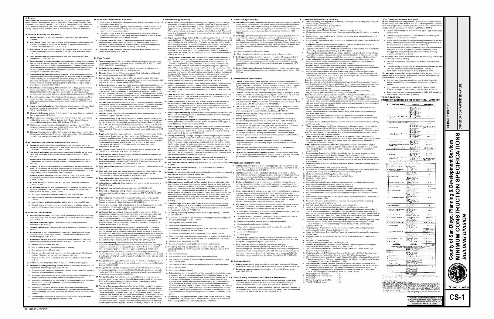
TABLE R602.3(1)
FASTENER SCHEDULE FOR STRUCTURAL MEMBERS
E. Wood Framing (Continued)
49. Fireblocking of chimneys and fireplaces. All spaces between chimneys and floors and
ceilings through which chimneys pass shall be fireblocked with noncombustible material
securely fastened in place. The fireblocking of spaces between chimneys and wood
joists, beams, or headers shall be self-supporting or be placed on strips of metal or metal
lath laid across the spaces between combustible material and the chimney. (CRC
R1003.19)
50. Draftstopping. In combustible construction where there is usable space both above and
below the concealed space of a floor/ceiling assembly, draftstops shall be installed so
that the area of the concealed space does not exceed 1000 square feet. Draftstopping
shall divide the concealed space into approximately equal areas. Where the assembly is
enclosed by a floor membrane above and a ceiling membrane below, draftstopping shall
be provided in floor/ceiling assemblies under the following circumstances (CRC
R302.12):
a. Ceiling is suspended under the floor framing
b. Floor framing is constructed of truss-type open-web or perforated members
51. Draftstopping materials. Draftstopping shall not be less than 1/2-inch gypsum board,
3/8-inch wood structural panels, or other approved materials adequately supported.
Draftstopping shall be installed parallel to the floor framing members unless otherwise
approved by the building official. The integrity of draftstops shall be maintained. (CRC
R302.12.1)
52. Combustible insulation clearance. Combustible insulation shall be separated minimum
3 inches from recessed luminaires, fan motors, and other heat-producing devices. (CRC
R302.14)
F. General Material Specifications
1. Lumber. All joists, rafters, beams, and posts 2-inches to 4-inches thick shall be No. 2
grade Douglas Fir-Larch or better. All posts and beams 5 inches and thicker shall be No.
1 grade Douglas Fir-Larch or better. Studs not more than 8 feet long shall be stud-grade
Douglas Fir-Larch or better when supporting not more than one floor, roof, and ceiling.
Studs longer than 8 feet shall be No. 2 grade Douglas Fir-Larch or better.
2. Concrete. Concrete shall have a minimum compressive strength of 2,500 psi at 28 days
and shall consist of 1 part cement, 3 parts sand, 4 parts 1-inch maximum size rock, and
not more than 7-1/2 gallons of water per sack of cement. (CRC R402.2)
3. Mortar. Mortar used in construction of masonry walls, foundation walls, and retaining
walls shall conform to ASTM C 270 and shall consist of 1 part portland cement, 2-1/4 to 3
parts sand, and 1/4 to 1/2 part hydrated lime. (CBC 2103.2)
4. Grout. Grout shall conform to ASTM C 476 and shall consist of 1 part portland cement,
1/10 part hydrated lime, 2-1/4 to 3 parts sand, and 1 to 2 parts gravel. Grout shall attain
a minimum compressive strength of 2,000 psi at 28 days. (CBC 2103.3)
5. Masonry. Masonry units shall comply with ASTM C 90 for load-bearing concrete
masonry units. (CBC 2103.1)
6. Reinforcing steel. Reinforcing steel used in construction of reinforced masonry or
concrete structures shall be deformed and comply with ASTM A 615. (CBC 2103.4)
7. Structural steel. Steel used as structural shapes such as wide-flange sections,
channels, plates, and angles shall comply with ASTM A36. Pipe columns shall comply
with ASTM A53. Structural tubes shall comply with ASTM A500, Grade B.
8. Fasteners for preservative-treated wood. Fasteners for preservative-treated and
fire-retardant-treated wood - including nuts and washers -- shall be of hot dipped
zinc-coated galvanized steel, stainless steel, silicon bronze, or copper. (CRC R317.3.1)
Exception: 1/2-inch diameter or greater steel bolts
Exception: Fasteners other than nails and timber rivets may be of mechanically
deposited zinc-coated steel with coating weights in accordance with ASTM B 695,
Class 55 minimum
Exception: Plain carbon steel fasteners acceptable in SBX/DOT and zinc borate
preservative-treated wood in an interior, dry environment
9. Fasteners for fire-retardant-treated wood. Fasteners for fire-retardant-treated wood
used in exterior applications or wet or damp locations shall be of hot dipped zinc-coated
galvanized steel, stainless steel, silicon bronze, or copper. (CRC R317.3.3)
G. Roofing and Weatherproofing
1. Roof covering. All roof covering shall be installed per applicable requirements of CBC
1507. Roof coverings shall be at least Class A rated in accordance with ASTM E 108 or
UL 790. (County Building Code 92.1.1505.1)
2. Roof flashing. Flashing shall be installed at wall and roof intersections, at gutters,
wherever there is a change in roof slope or direction, and around roof openings. Where
flashing is of metal, the metal shall be corrosion-resistant with a thickness of not less
than 0.019 inch (No. 26 galvanized sheet). (CRC R903.2.1)
3. Crickets and saddles. A cricket or saddle shall be installed on the ridge side of any
chimney or penetration more than 30 inches wide as measured perpendicular to the
slope. Cricket or saddle covering shall be sheet metal or the same material as the roof
covering. (CRC R903.2.2)
4. Water-resistive barrier. A minimum of one layer of No. 15 asphalt felt shall be attached
to studs or sheathing of all exterior walls. Such felt or material shall be applied
horizontally, with the upper layer lapped over the lower layer minimum 2 inches. Where
joints occur, felt shall be lapped minimum 6 inches. The felt shall be continuous to the
top of walls and terminated at penetrations and building appendages in a manner to
maintain a weather-resistant exterior wall envelope. (CRC R703.2)
5. Wall flashing. Approved corrosion-resistant flashing shall be applied shingle fashion at
the following locations to prevent entry of water into the wall cavity or penetration of
water to the building structural framing components (CRC R703.8):
a. Exterior door and window openings, extending to the surface of the exterior wall finish
or to the water-resistive barrier for subsequent drainage
b. At the intersection of chimneys or other masonry construction with frame or stucco
walls, with projecting lips on both sides under stucco copings
c. Under and at the ends of masonry, wood, or metal copings and sills
d. Continuously above all projecting wood trim
e. Where exterior porches, decks, or stairs attach to a wall or floor assembly of
wood-frame construction
f. At wall and roof intersections
g. At built-in gutters
6. Dampproofing. Dampproofing materials for foundation walls enclosing usable space
below grade shall be installed on the exterior surface of the wall, and shall extend from
the top of the footing to finished grade. (CRC R406.1)
7. Weep screed. A minimum 0.019-inch (No. 26 galvanized sheet gage),
corrosion-resistant weep screed or plastic weep screed with a minimum vertical
attachment flange of 3-1/2 inches shall be provided at or below the foundation plate line
on exterior stud walls in accordance with ASTM C 92. The weep screed shall be placed
a minimum 4 inches above the earth or 2 inches above paved areas and shall be of a
type allowing trapped water to drain to the exterior of the building. (CRC R703.7.2.1)
H. Grading and soils
1. Grading permit. Grading permit required if volume of earth moved exceeds 200 cubic
yards or if any cuts or fills exceed 8 feet in height/depth. (County Grading Ordinance 202)
2. Compaction report. Compaction report required for fill material 12 inches or more in
depth. (CBC 1803.5.8)
I. Green Building Standards Code (CALGreen) Requirements
1. Applicability. CalGreen residential mandatory measures shall apply to every newly
constructed building or structure and within any addition or alteration increasing a
building's conditioned area, volume, or size. (CalGreen 101.3, CalGreen 301.1.1)
Exception: All residential buildings undergoing permitted alterations, additions, or
improvements shall replace noncompliant plumbing fixtures with water-conserving
plumbing fixtures per CalGreen 301.1.1 and CalGreen 4.303.1
I. (CALGreen) Requirements (Continued)
16. Moisture content of building materials. Building materials with visible signs
of water damage shall not be installed. Wall and floor framing shall not be enclosed
when the framing members exceed 19 percent moisture content. Moisture content
shall be verified in compliance with the following (CALGreen 4.505.3):
a. Moisture content shall be determined with either a probe-type or contact-type
moisture meter.
b. Moisture readings shall be taken at a point 2 feet to 4 feet from the grade
stamped end of each piece to be verified.
c. At least three random moisture readings shall be performed on wall and floor
framing with documentation acceptable to the enforcing agency provided at
the time of approval to enclose the wall and floor framing.
Insulation products which are visibly wet or have high moisture content shall
be replaced or allowed to dry prior to enclosure in wall or floor cavities.
Wet-applied insulation products shall follow the manufacturers' drying
recommendations prior to enclosure.
17. Bathrooms with a bathtub and/or shower shall be mechanically ventilated per
the following (CalGreen 4.506.1):
a. Fans shall be ENERGY STAR compliant and ducted to terminate outside
building
b. Unless functioning as a component of a whole-house ventilation system, fans
shall have humidity controls capable of adjustment - manually or
automatically -- between a relative humidity range of 50% to 80%.
18. Heating and air-conditioning system design. Heating and air-conditioning
systems shall be sized, designed, and have their equipment selected using the
following methods (CALGreen 4.507.2):
a. The heat loss and heat gain is established according to ANSI/ACCA 2
Manual J, ASHRAE handbooks, or other equivalent design software or
methods.
b. Duct systems are sized according to ANSI/ACCA 1 Manual D 2009,
ASHRAE handbooks, or other equivalent design software or methods.
c. Select heating and cooling equipment according to ACCA 36-S Manual S or
other equivalent design software or methods