Embed Size (px)
Citation preview

Heterogeneous Solids: Possible Representation.Schemes
Stephane M. [email protected]
Georges M. [email protected]
Clemson Research in EngineyringDesign and OptimizationDept. of l\4.echanicalpngineering
Clemson University,Clemson, SC 29634-0921
AbstractSolid freeform fabrication processes allow parts to be built with accuracy and mechanical
integrity, permittingthem to be used in tooling or fOrlnandfit applications. There is already a needform~lti ..color Parts. for surgical applications, which will eventually lead to. multi-material RP.machines.WhetherJor on the spot color deposition or for functionally tailored multiple materialsparts,.RPmachines with such capabilities are becoming available. They will eventually lead to thetrtiepromise of Solid Freeform Fabrication: a system that can build a functional mechanismwithout assembly, and from multiple materials. This paper is aimed at understanding the newchallenges raised from representing solids whose material distribution is changing gradually fromone material to another (HC), and those made of a collection .of discrete materials (HD). Severalrepresentation schemes are reviewed and critiqued. Techniques borrowed from medical imagingand geoscience modeling are used to better understand the modeling of heterogeneous and gradientsolids, from a geometric standpoint.
Problem StatementCurrent solid modeling technologies model an object using its boundaries, implicitly
making the assumption that the interiofof the solid is made of a single, homogeneous material.Recent progress in commercial RP solutions [1] will allow parts to be built with localizedmechanical properties. Thus, as more efforts are directed· towards material optimization techniques[2],[3] there isa need to shift the focus of a solid representation scheme from the geometry to a.more abstract attribute..oriented representation scheme. In such a representation, the geometry of anobject as it is conventionally known, would become the. residual of all the spaces spanned by theattributes under consideration. Example attributes are: thermal properties, mechanicalcharacteristics, electrical conductivity and density.
2 Rapid Prototyping
The enabling technology behind the creation of heterogeneous objects has to be able tooutput an artifact representing an object designed with a computer. RapidPrototyping (RP) seemsto be the medium of choice in such applications. RPembodies digital. designs into. physicalmockups in a matter of hours. The techniques behind the RP process rely on the ability to add(and/or in some casesremove~, material at anyarbitraryloqatipn.inspGlce.. Therearetwogeneralclasses .. of RP processes (even though combinations do exist): .additive-based processes andremoval..based processes. The distinction between the processes depends on whetherthe processadds.material to reach the final shape ofthe.artifact, orifitre1110vesmateriaLfromabulkto.reach
187

that same shape. The following two sections review those two important families of processes. Thisreview is by all means non-exhaustive, and is here only to· briefly outline the principles behindthem. Further description of RP processes is proposed in [4].
Additive Processes
Additive processes involve the following or a variation thereof: the object to bemanufactured is broken down.in layers and the part is built from bottom to top by stacking crosssections of the object. Each'layerismanufactured byway of an additive process, one at a time and
a setorder, then the object isshiftedd9Wtl to allow the next layer to be added.
Some of the enabling technologies.behind additive processes are based on the hardening ofa photo-polymer by a laser (SLA) or by ultra-violet floodlights (SOC), or the cutting of an adhesivepaper (LOM). Another variation, in powder-based processes, is to sinter a bin of finely grainedpowder (SLS) [5]. Some processes also rely on a thermoplastic plotting system, akin to an inkjetplotter to deposit the material (FDM, .3Dprinters).• Many .of those processes require additionalsupport structures to maintain the artifacts' structural integrity throughout the building stage, thusrequiring the additional step of part cleanup.
Some RP makers use a color-coded support material whose removal does not riskobliterating a feature from the part. In some other cases, the technological choice of the processprevents from using a secondary·material, and the support structures and the part both share thesame material, with the exception being that the support structure is attached to the part onlytemporary by a breakable junction.
2.2 Removal ProcessesThis class of processes is more on a par with traditional manufacturing technologies.
Essentially, it involves milling, grinding or cutting material from a bulk of raw material. Thoughthis technique certainly has more limitations than the additive processes (recessed pockets are oneof them), it does provide a valid alternative to obtain mechanical parts with properties and finishthat are often unattainable with additive processes.
The bulk material is typically made of a ductile material, which can be cut at a great rate ofspeed to quicken the process. Example materials are aluminum, steel, Styrofoam and balsa. It isobvious that for manufacturing reasons, the bulk material should be made of a single material,otherwise the rate of cutting will vary from one material to the next, resulting in uneven surfaces,or rips at the interface between the two materials.
3 Solid Modeling Representation SchemesTraditional mechanical design encompasses several tasks and disciplines. For instance,
designing a car's body involves considerations of structural soundness, ergonomics, aerodynamics,vehicle dynamics, aesthetics and after-life disposability. In addition, modem engineering oftenprofesses some form of optimality which insures that a designed product responds ideally to a setof constraints, both from the consumers' and from the manufacturer's perspectives.
It is evident that today's design cycles are complex, demanding and expensive, and that theinterplay of different disciplines requires rugged tools to assist the designers and to support

collaborative and concurrent work. The widespread use of computers has greatly contributed toreduce the time required to perform the aforementioned activities, leading to a design cycle nearly100% digital (i.e. performed entirely on computers).
Ideally, the enabling technology behind a digital design cycle is made of tightly integratedsoftware tools revolving around a central application called a CAD (Computer Aided Design)System. Most CAD Systems are mature software products, sometimes resulting from a decade ofresearch or more. Behind all these CAD Systems is the ability to portray a product in arepresentation allowing the modifications, simulations and variations encountered during thedesign phase. Since mechanical design has always been concerned with the dimensioning of parts,a natural choice for this representation is based on the geometric features of a product and itsdimensions. This is referred to as solid modeling, and the next section will briefly review thef(~presentation concepts behind the various modelers found in CAD Systems today.
3.1 Boundary Representation Schemes (B-Rep.)The B-Rep is a surface boundary representation where solids are defined by a list of their
enclosing surface boundaries. This representation originated from the definition of a polyhedra: it ismade from polygons, which are made from triangles, which in turn are made from edges and lastlyedges are made from vertices. The representation was then further expanded to include arbitraryrepresentations (Beziers patches or NURBS surfaces) for the enclosing surfaces. The surfaceboundaries are oriented such that given any surface point, the solid interior can be easilydetermined. For instance, a pyramid with a square base is made of four triangles and a square(Figure 1). This representation is notably good at representing most solids and especially the detailsembedded in complex shapes, though a known drawback of the B-Rep is the difficulty to verifywhether or not a solid is closed or topologically valid.
This difficulty emanates from the task of inferring from the enclosing surfaces (typicallysurfaces described by two parameters) that a valid, closed 3D entity is defined. A solid is closedwhen the enclosing boundaries form a closed/fixed volume. A solid is valid if it does not selfintersect. For a more rigorous description of a B-Rep solid topology and its problems, refer to [6].
L 7Figure 1: A Boundary Representation for a Pyramid with a Square Base.
189
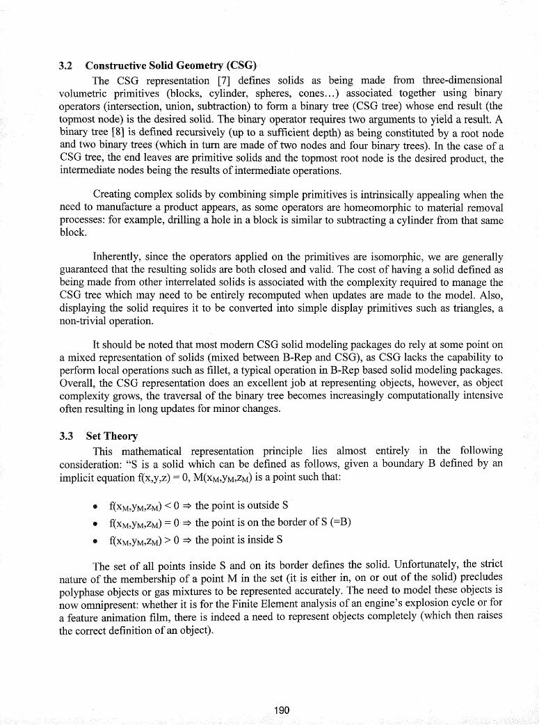
3.2 Constructive Solid Geometry (CSG)The GSG· representation [7] defines solids as being made from three-dimensional
volumetric primitives (blocks, cylinder, spheres, cones ... ) associated together using binaryoperators {intersection, union, subtraction) to form a binary tree (CSG tree) whose end result (thetopmost node) is the desired solid. The binary operator requires two arguments to yield a result. Abinary tr~.e [8] is defined recursively (up to a sufficient depth) as being constituted by a root nodeand two binary trees (which in tum are made of two nodes and four binary trees). In the case of aCSG tree,. the end leaves are primitive solids and the topmost root node is the desired product, theintermediate nodes being the results of intennediate operations.
Creating complex solids by combining simple primitives is intrinsically appealing when theneed to l11anufacture a product appears, as some operators are homeomorphic to material· removalprocesses: for example, drilling a hole in a block is similar to subtracting a cylinder from that sameblock.
Inherently, since the operators applied on the primitives are isomorphic, we are generallyguaranteed that the resulting solids are both closed and valid. The cost of having a solid defined asbeing made from other interrelated solids is associated with the complexity required to manage theCSG tree which may need to be entirely recomputed when updates are made to the model. Also,displaying the solid requires it to be converted into simple display primitives such as triangles, anon-trivial operation.
It should be noted that most modern GSG solid modeling packages do rely at some point ona mixed representation of solids (mixed between B-Rep and GSG), as GSG lacks the capability toperform local operations such as fillet, a typical operation in B-Rep based solid modeling packages.Overall, the GSG representation does an excellent job at representing objects, however, as objectcomplexity grows, the traversal of the binary tree becomes increasingly computationally intensiveoften resulting in long updates for minor changes.
3.3 Set TheoryThis mathematical representation principle lies almost entirely in the following
cOnsideration: "S is a solid which can be defined as follows, given a boundary B defined by animplicit equation f(x,y,z) = 0, M(XM,YM,ZM) is a point such that:
• f(xM,YM,zM) < 0 => the point is outside S
• f(xM,YM,zM) = 0 => the point is on the border of S (=B)
• f(xM,YM,zM) > 0 => the point is inside S
The set of all points inside S and on its border defines the solid. Unfortunately, the strictnature of the membership of a point M in the set (it is either in, on or out of the solid) precludespolyphase objects or gas mixtures to be represented accurately. The need to model these objects isnow omnipresent: whether it is for the Finite Element analysis of an engine's explosion cycle or fora feature animation film, there is indeed a need to represent objects completely (which then raisesthe correct definition of an object).
190

Used initially for manufacturing, this set-based representation for solids has been outgrownby the demands put on it. An example application for this repr~sehtation is svLis 3.0, a set theoricbased solid modeling kernel [9]. This kernel allows Boolean operations to be performed on solidsrepresented using set theory. Nevertheless, the problem at hand and the advances in modernmanufacturing processes are now raising new interest in this representation:
II Ability to have multiple membership for a point (e.g. being part of several materials),II Allow porous models to be created,II Allow one (or more) materials to blend graduallyII Allow mechanical/thermal/electrical/... properties to be specified locally
4 Volumetric Representations
4.1 VoxelsTwo definitions are commonly found for a voxel, the basic unit of a volumetric
representation:
II A voxel, like a pixel, has 0 dimension. Akin to the way that a digital image isrepresented by an array of pixels, a volumetric dataset is made of voxels laid out on aregular 3D grid. For every voxel in this dataset, a scalar value quantifies themembership of this voxel to a given reference material. Often, such a representation canbe termed 'spatial enumeration.'
II A voxel can also be considered to be a cube of small size.
There is no strict definition for a voxel, but we will choose to remain consistent with thedefinition of a pixel and say that the voxel is a 3D extension of a pixel and thus, has nodimensionality.
4.1.1 Volume RenderingThanks to constant increases in the computing power of desktop computers, Volume
Rendering, traditionally reserved to medical imaging, is now finding its way in areas such as failureanalysis, computational fluid dynamics and meteorology. Though volume rendering [10] merelyrefers to the act of rendering volumetric data, our primary concern is not with this task,· but ratherwith the underlying representation of the data to be rendered, along with some of the conceptsinvolved in the handling of this data.
Initially, volumetric data was gathered from Magnetic Resonance Imaging (MRI) scanners.These scanners gather data from human organs by measuring the energy received from disruptedatoms as they realign after being subject to an out-of-phaseexcitation signal. Since tissues ofsimilar composition exhibit similar responses to this out-of-phase, signal .• consistency is insured inthe interpretation of the data. The snapshot of a cross section is developed by using this response asa basis for the computation. of the light intensity of the pixels constituting the snapshot.Conceptually, the scanning of the organs is made in all three planes at the same time but a phaseshift· in the excitation signal· (for all three planes) generates a phase shift in the restituting signal,which allows cross section images to be isolated. Without computers, a doctors' attention has to
191

span several cross sections ata time to correctly interpret the 3D dimensional nature of the organs.Stacking the cross sectionsin3D space not .only helped minimize errors of interpretation but alsoprovided doctors and surgeons witha3D image that could be panned, zoomed and rotated to betterlocate individual details.
The. principles of Volume Rendering are similar to those of raytracing: for every pixel onthe view plane, a ray of light is cast orthogonal to the view plane and directed toward the objects tobe rendered. Each elementary element of volume (termed a voxel) intersecting the ray, iscomposited (or combined) with other intersecting voxels to provide the final light intensity of thepixel on the view plane. Since this computation is performed repeatedly for every view generatedof the volume, a weight can be attributed for voxels of similar absorption to filter out some tissueswhile emphasizing other. A noteworthy recipient of these techniques is the Visible Human [11],where a man's body was entirely digitized through a similar process, resulting in 1800 crosssections of his body (1000 transverse and coronal MR scans, 1878 transverse scans wicorresponding photographs).
4.1.2 Voxel Based Representations
Volumetric data sets emanating from human organs are extremely dense, and much of thevoxels forming the volume are non-empty. Thus there is little incentive to design space efficientdata-structures. The main efforts made to improve the storage of volumetric datasets are aimed atimproving the speed of volume rendering algorithms by preprocessing the voxels [12], [13] andskipping empty cells [14]. The use of voxels to represent matter raises an interesting issue when itcomes to render the outer surfaces of objects. These surfaces exhibit a shape that is ofteninappropriately captured by voxels. Nevertheless, these surfaces are rendered as if they wheredescribed by a conventional polygonal mesh using a normal estimation algorithm and aninterpolation kernel [15]. The improvement over 'naIve' volume rendering is certainly significant,but interpolating the surfaces makes it difficult to use this technique for solid modeling wheresurfaces are often designed with strict tolerances.
Additionally, since the voxels are a sampling of physical data, the storage requirements forthose sets are severe: a model containing a grid made from 512 arrays of 512x512 voxels uses atthe very least 128 M-byte of memory (for 1 bit encoding). The data set is usually very large andthus not easily held in main memory without using some form of virtual memory. Anotherapplication of a voxel based modeling scheme for solids is also presented in [16], where the aim isto see how a voxel-based modeling fits within an RP enabled manufacturing environment.
It should be noted that the use of voxels for solid modeling does greatly simplify CSGoperations on solids [14]: Boolean operations performed on solids are reduced to plain voxel tovoxel operations whose outcomes are extremely simple to compute. For instance, an empty voxelintersecting a full voxel is an empty voxel, an empty voxel 'union' a full voxel is a full voxel.
OctreesSamet [17] proposed to use a hierarchical space-partitioning scheme in order to store
volumetric data, specifically the Octree. The principles of an octree are simple: to recursivelysubdivide a cube into 8 smaller cells 1/8th the size of the original cube, until either the cube is
192
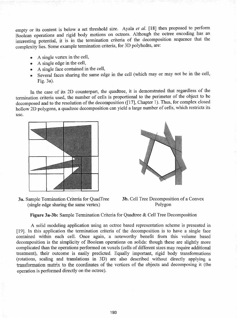
empty or its content is below a set threshold size. Ayala et al. [18] then proposed .to performBoolean operations and rigid body motions on octrees. Although the octree encodIng has aninteresting potential, it is in the termination criteria of the decomposition sequence that thecomplexity lies. Some example termination criteria, for 3D polyhedra, are:
• A single vertex in the cell,• A single edge in the cell,• A single face contained in the cell,• Several faces sharing the same edge in the cell (which mayor may not be in the cell,
Fig.3a).
In the case of its 2D counterpart, the quadtree, it is demonstrated that regardless of thetermination criteria used, the number of cells is proportional to the perimeter of the object to bedecomposed and to the resolution of the decomposition ([17], Chapter 1). Thus, for complex closedhollow 2D polygons, a quadtree decomposition can yield a large number of cells, which restricts itsuse.
3a. Sample Termination Criteria for QuadTree(single edge sharing the same vertex)
3b. Cell Tree Decomposition of a ConvexPolygon
Figure 3a-3b: Sample Termination Criteria for Quadtree & Cell Tree Decomposition
A solid modeling application using an octree based representation scheme is presented in[19]. In this application the termination criteria of the decomposition is to have a single facecontained within each cell. Once again, a noteworthy benefit from this volume baseddecomposition is the simplicity of Boolean operations on solids: though these are slightly morecomplicated than the operations performed on voxels (cells of different sizes may require additionaltreatment), their outcome is easily predicted. Equally important, rigid body transformations(rotations, scaling and translations in 3D) are also described without directly applying atransformation matrix to the coordinates of the vertices of the objects and decomposing it (theoperation is performed directly on the octree).
193
4.1.4 The Cell TreeThe Cell Tree [20] is an encoding for general polyhedral pointsetsofarbittarydimensions
(bounded or unbounded). This encoding represents a polyhedral bythe algebraic sum of simpler,convex polyhedra. (holes are·' subtrapted').•Each•convex .polyhedral chain is described by theintersection of halfspaces and represented in a vector (Fig. 3b). A halfspace partitions an ndimensional space in halves, and is a hyperplane of dimension n-1. The representation is assumedto be minimal: a halfspace not intersecting any other halfspace (e.g. empty intersection) is removedfrom the vector. Also, since the description is minimal, a halfspace is a boundary of the convexpolyhedral it is describing. To further normalize this representation, the halfspaces used in thedescription of a polyhedral are listed in a single location. A convex polyhedral is then representedusing a list of 1s, -1 s and Os referring to whether or not this polyhedral is respectively using a givenhalfspace, its opposite or not using it.
Performing Boolean operations on polyhedra is then a slightly more complicated matterthan with the previous representation schemes, though it does not necessitate elaborated algorithms.The union of two polyhedra involves merging the two databases of halfspaces and adding moreconvex polyhedra to the chain. Subtracting a polyhedral is a similar task, since the descriptionallows unbounded polyhedra, the complementary of the polyhedral to be.subtracted is created bynegating the list of vectors it uses, and then added to the convex polyhedra chain.
It is interesting to note that this representation offers some features that other representationdo not: in the case of 3D polyhedra, there is no need to evaluate the vertices or the edges, strictlyspeaking, the entire shape is represented using only planes. However, a very stringent requirementin this representation is that every 3D solids must have a convex decomposition.
4.1.5 Geoscience ModelingGeoscience modeling shares some similitude with mechanical CAD, especially in the area
of domain (2D or 3D) representation: 2D geographic domains can be represented by way ofpolygons, and a 3D hill can be represented with a set of 2D elevation maps. The added dimensionof attributes such as soil composition, humidity and erosion tends to make this modeling certainlyvery relevant for the problem at hand. The critical aspects relevant to us in geoscience modeling[21] are those of uncertainty and fuzziness of the boundaries of the objects described.
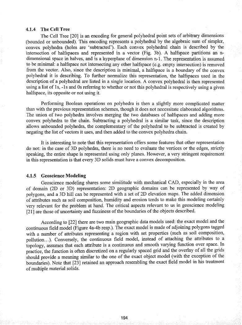
According to [22] there are two main geographic data models used: the exact model and thecontinuous field model (Figure 4a-4b resp.). The exact model is made of adjoining polygons taggedwith a number of attributes representing a region with set properties (such as. soil composition,pollution... ). Conversely, the continuous field model, instead of attaching the attributes to atopology, assumes that each attribute is a continuous and. smooth varying function over space. Inpractice, the function is often discretized on a regularly spaced grid and the overlay of all the gridsshould provide a meaning similar to the one of the exact object model (with the exception of theboundaries). Note that [23] retained an approach resembling the exact field model in his treatmentof multiple material solids.
1

Model
Property #1
Property #2
Property #3
Property #4
Property #5
Range of Values forAttribute #2
for
4b. The Continuous Model (discretized),
ILl'.......,......."" 4a..4b. Geographic Data Models
Strictly speaking, heterogeneous solids do not have any uncertainties associated withboundary definition. Evidently, the designer of a part knows exactly where a material is and whereit isn't. It is to hoW for example a soil boundary is modeled and how the I.ILH.l.LL;::;'1.I
of a soil (which is often gradual) is treated in terms of fuzziness of the set (the uncertainty,measurement errors, is not relevant here). soils, the "core" region is defined as the regionattains maximal membership in a given attribute, while the boundary is defined as the regionattaining between 0 and the maximal membership (the latterinterval being open on both ends). Theuse of fuzzy logic to model the boundary is proposed [24] and a similar approach, pertaining to agradual change between two materials is certainly an interesting issue. A more elaborate discussionto differentiate a 'Boolean region' from a 'fuzzy region' is presented in [22]. The discussionillustrates why the problem of point membership in a region can not always be a true or falseanswer in terrain modeling.
5 Objects Approach at the University of MichiganInitially, the University of Michigan's efforts were aimed at a theoretical approach to
representing heterogeneous solids, [23], [25], [26]. representation of a solid made from nmaterials was viewed as an application from the geometrical space to the primary material space[23]. In this context, an n-dimensional vector is associated to every triple (x, y, z) within the solidunder consideration. n-dimensional vector represents the material composition as acombination ofthe primary materials, such that the sum of all the equals toone. Regularized set operations are· then defined on these solids. another workseveral blending functions between primary materials are extracted from the literature [28]. Notethat no detailed representation structure of the data is proposed to date
It is only recently [27], with the use of a DMD (Direct Material Deposition) apparatus thatthe attention has shifted to entire design process: from design to manufacturing while includingdesign homogenization to obtain the ideal microstructure pattern distribution. The material isconsidered at the microstructure level, which evidently translates into large· amounts of data andmany variables to consider during the optimization stage. representatipn lacks the ability togroup together a large number of similar microstructures to reduce the amount of data needed.
195

6 ConclusionSeveral representation schemes have been reviewed. As expected, there is a need ~o
combine the features of traditipnalmechanical representations with the feat\.lres of volumetncrepresentations. There is no perfect. solution in any of the prevalent represe~tati?n schemes.' andeffort must target either the development of novel schemes or the combmatlon of aVailablerepresentations. Furthermore, once the problem of material representation is resolved, these samyprinciples can be applied to other· types of attributes such as electrical conductivity or thermalresistance. This will allow heterogeneous solids to be completely and entirely represented.
7 References[1]. Swann T.A, Keicher D.M., and Miller W.D. "Laser Engineered Net Shaping (LENSTM)Technology Commercialization." Rapid Prototyping and Manufacturing '98, Dearborn, MI.
[2]. Konig O. (1999). "Application of Genetic Algorithms in the Design of Multimaterial StructuresManufactured in Rapid Prototyping," Diploma Thesis, ETH Zurich, Zurich, Switzerland.
[3]. Huang J., and Fadel G.M. (1999). "Heterogeneous Flywheel Modeling & Optimization."Journal ofMaterials. & Design(Special Issue: Rapid Prototyping and Manufacturing).
[4]. Jacobs P.P. (1996). Stereolithography and other RP&M Technologies, ASME Press.
[5]. Deckard C.R. (1988). "Selective Laser Sintering," Ph.D., University of Texas, Austin, TX.
[6]. Hoffmann C. M. (1989). Geometric and Solid Modeling, An Introduction, Morgan KaufmannPublisher Inc., San Mateo.
[7]. Requicha A A G., and Voelcker H. B. (1983). "Solid Modeling: Current Status and ResearchDirections." IEEE Computer Graphics Applications(October 1983),25-37.
[8]. Wood D. (1993). Data Structures, Algorithms, and Performance, Addison-Wesley, New York.
[9]. Bowyer A, Bayliss G., Berchtold J., Eisenthal D., Martin R, Parry-Barwick S., Pidcock D.,Taylor R, Voiculescu I., Wallis A, and Wise K (1999). "svLis 3.0 - The SvLis Set-theoreticKernel Geometric Modeller Version 3.0." http://www.bath.ac.ukl~ensab/G_modlSvlisl.
[10]. Sabella P. (1988). "A Rendering Algorithm for Visualizing 3D Scalar Fields." ComputerGraphics, 22(August 1988), 51-59.
[11]. Various authors. (1996). The Visible Human Project Conference Proceedings, NationalInstitutes of Health, William H. Natcher Conference Center, Bethesda, Maryland USA
[12]. Freund J., and Sloan K "Accelerated Volume Rendering Using Homogeneous RegionEncoding." IEEE Visualization, 191-197.
[13]. Mueller K, and Yagel R (1996). "Fast Perspective Volume Rendering with Splatting byUtilizing a Ray-Driven Approach." IEEE Computer Graphics and Applications(July 1996), 65-72.
[14]. Shareef N., and Yagel R "Rapid Previewing via Volume-Based Solid Modeling." ThirdSymposium on Solid Modeling and Applications, Salt Lake City, 281-291.
[15]. Moller T., Machiraju R, Mueller K, and Yagel R "A Comparison of Normal EstimationSchemes." IEEE Visualization, 19-26.
196

[16]. Chandru V., Manohar S., and Prakash (1995). "Voxel-Based Modeling for LayeredManufacturing." IEEE Computer Graphics and Applications(November 1995),42-47.
[17]. Samet (1989). The Design and Analysis ofSpatial Data Structures, Addison-Wesley.
[18]. Ayala D., Brunet P., Juan R., and Navazo I. (1985). "Object Representation by Means ofNonminimal Division Quadtrees and Octrees." ACM Transactions on Graphics, 4(1), 41-59.
[19]. Meagher D. (1982). "Geometric Modeling Using Octree Encoding." Computer Graphics andImage Processing, 19, 129-147.
[20]. Gunther O. (1988). Efficient Structures for Geometric Data Management, Springer-Verlag.
[21]. Burrough P.A., and Frank A.U. (1996). Geographic Objects with Indeterminate Boundaries,Taylor & Francis.
[22]. Fisher (1996). "Boolean and Fuzzy Region." Geographic Objects with IndeterminateBoundaries, Burrough P. A. and Frank A. U., eds., Taylor & Francis, 87-94.
[23]. Kumar V., and Dutta D. "An Approach to Modeling Multi-Material Objects." ThirdSymposium on Solid Modeling and Applications, Atlanta, GA, 336-343.
[24]. Usery (1996). "A Conceptual Framework and Fuzzy Set Implementation for GeographicFeatures." Geographic Objects with Indeterminate Boundaries, Burrough P.A. and Frank A.U.,eds., Taylor & Francis, 71-85.
[25]. Kumar V., and Dutta D. "Solid Model Creation for Materially Graded Objects." Symposiumon Solid Freeform Fabrication, 613-620.
[26]. Kumar V., Burns D., Dutta D., and Hoffman C. (1998). "A Framework for Object Modeling."UM-MEAM-98-07, CADCAM Group, Ann Arbor.
[27]. Dutta Ghosh A.K., Kikuchi N., and Mazumder J. "Design, Representation and Fabricationof Designed Materials." ASME Energy Sources Technology Conference, Houston, TX.
[28]. Bhashyam S., Shin K. and Dutta D., "An Integrated CAD System for Design ofHeterogeneous Objects." UM-MEAM-99-08, CADCAM Group, Ann Arbor.
197

198