Embed Size (px)
Citation preview
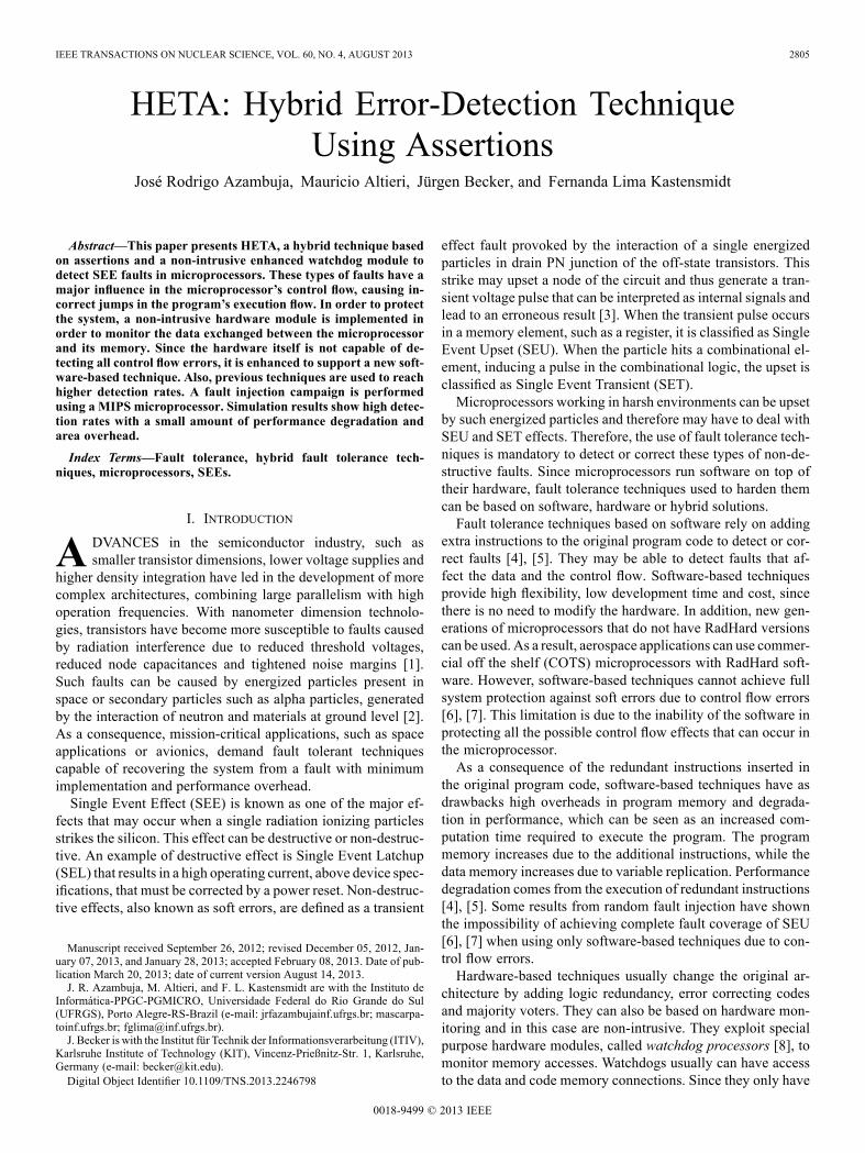
IEEE TRANSACTIONS ON NUCLEAR SCIENCE, VOL. 60, NO. 4, AUGUST 2013 2805
HETA: Hybrid Error-Detection TechniqueUsing Assertions
José Rodrigo Azambuja, Mauricio Altieri, Jürgen Becker, and Fernanda Lima Kastensmidt
Abstract—This paper presents HETA, a hybrid technique basedon assertions and a non-intrusive enhanced watchdog module todetect SEE faults in microprocessors. These types of faults have amajor influence in the microprocessor’s control flow, causing in-correct jumps in the program’s execution flow. In order to protectthe system, a non-intrusive hardware module is implemented inorder to monitor the data exchanged between the microprocessorand its memory. Since the hardware itself is not capable of de-tecting all control flow errors, it is enhanced to support a new soft-ware-based technique. Also, previous techniques are used to reachhigher detection rates. A fault injection campaign is performedusing a MIPS microprocessor. Simulation results show high detec-tion rates with a small amount of performance degradation andarea overhead.
Index Terms—Fault tolerance, hybrid fault tolerance tech-niques, microprocessors, SEEs.
I. INTRODUCTION
A DVANCES in the semiconductor industry, such assmaller transistor dimensions, lower voltage supplies and
higher density integration have led in the development of morecomplex architectures, combining large parallelism with highoperation frequencies. With nanometer dimension technolo-gies, transistors have become more susceptible to faults causedby radiation interference due to reduced threshold voltages,reduced node capacitances and tightened noise margins [1].Such faults can be caused by energized particles present inspace or secondary particles such as alpha particles, generatedby the interaction of neutron and materials at ground level [2].As a consequence, mission-critical applications, such as spaceapplications or avionics, demand fault tolerant techniquescapable of recovering the system from a fault with minimumimplementation and performance overhead.Single Event Effect (SEE) is known as one of the major ef-
fects that may occur when a single radiation ionizing particlesstrikes the silicon. This effect can be destructive or non-destruc-tive. An example of destructive effect is Single Event Latchup(SEL) that results in a high operating current, above device spec-ifications, that must be corrected by a power reset. Non-destruc-tive effects, also known as soft errors, are defined as a transient
Manuscript received September 26, 2012; revised December 05, 2012, Jan-uary 07, 2013, and January 28, 2013; accepted February 08, 2013. Date of pub-lication March 20, 2013; date of current version August 14, 2013.J. R. Azambuja, M. Altieri, and F. L. Kastensmidt are with the Instituto de
Informática-PPGC-PGMICRO, Universidade Federal do Rio Grande do Sul(UFRGS), Porto Alegre-RS-Brazil (e-mail: jrfazambujainf.ufrgs.br; mascarpa-toinf.ufrgs.br; [email protected]).J. Becker is with the Institut für Technik der Informationsverarbeitung (ITIV),
Karlsruhe Institute of Technology (KIT), Vincenz-Prießnitz-Str. 1, Karlsruhe,Germany (e-mail: [email protected]).Digital Object Identifier 10.1109/TNS.2013.2246798
effect fault provoked by the interaction of a single energizedparticles in drain PN junction of the off-state transistors. Thisstrike may upset a node of the circuit and thus generate a tran-sient voltage pulse that can be interpreted as internal signals andlead to an erroneous result [3]. When the transient pulse occursin a memory element, such as a register, it is classified as SingleEvent Upset (SEU). When the particle hits a combinational el-ement, inducing a pulse in the combinational logic, the upset isclassified as Single Event Transient (SET).Microprocessors working in harsh environments can be upset
by such energized particles and therefore may have to deal withSEU and SET effects. Therefore, the use of fault tolerance tech-niques is mandatory to detect or correct these types of non-de-structive faults. Since microprocessors run software on top oftheir hardware, fault tolerance techniques used to harden themcan be based on software, hardware or hybrid solutions.Fault tolerance techniques based on software rely on adding
extra instructions to the original program code to detect or cor-rect faults [4], [5]. They may be able to detect faults that af-fect the data and the control flow. Software-based techniquesprovide high flexibility, low development time and cost, sincethere is no need to modify the hardware. In addition, new gen-erations of microprocessors that do not have RadHard versionscan be used. As a result, aerospace applications can use commer-cial off the shelf (COTS) microprocessors with RadHard soft-ware. However, software-based techniques cannot achieve fullsystem protection against soft errors due to control flow errors[6], [7]. This limitation is due to the inability of the software inprotecting all the possible control flow effects that can occur inthe microprocessor.As a consequence of the redundant instructions inserted in
the original program code, software-based techniques have asdrawbacks high overheads in program memory and degrada-tion in performance, which can be seen as an increased com-putation time required to execute the program. The programmemory increases due to the additional instructions, while thedata memory increases due to variable replication. Performancedegradation comes from the execution of redundant instructions[4], [5]. Some results from random fault injection have shownthe impossibility of achieving complete fault coverage of SEU[6], [7] when using only software-based techniques due to con-trol flow errors.Hardware-based techniques usually change the original ar-
chitecture by adding logic redundancy, error correcting codesand majority voters. They can also be based on hardware mon-itoring and in this case are non-intrusive. They exploit specialpurpose hardware modules, called watchdog processors [8], tomonitor memory accesses. Watchdogs usually can have accessto the data and code memory connections. Since they only have
0018-9499 © 2013 IEEE

2806 IEEE TRANSACTIONS ON NUCLEAR SCIENCE, VOL. 60, NO. 4, AUGUST 2013
access to the memory, watchdogs do not detect faults that are la-tent inside themicroprocessor, as well faults in the register bank.Combining software-based techniques and watchdog seems in-teresting in order to increase the fault detection coverage in con-trol-flow errors.In this paper, the authors present a method to detect soft
errors in microprocessors using a non-intrusive enhancedwatchdog module that works in tandem with a software-basedtechnique. Previous software-based techniques are then addedto offer a complete solution against SEE errors. A fault in-jection campaign is performed in a Microprocessor withoutInterlocked Pipeline Stages (MIPS) microprocessor running aset of test-case applications. Experimental results prove boththe effectiveness and the feasibility of Hybrid Error-detectionTechnique using Assertions (HETA).The paper is organized as follows. Section II presents pre-
vious work. Section III describes HETA. Section IV presentsprevious work used in the work and combined with HETA.Section V describes the methodology and hardware implemen-tation. Section VI presents the fault injection campaign and re-sults. Section VII presents main conclusions and future work.
II. RELATED WORK
Faults affecting microprocessor systems can be divided intotwo groups: faults affecting the data path and faults affectingthe control path. The first group comprises faults in the datastructures of the system, such as data storing variables. Suchfaults induce the system to an incorrect result, but do not changethe program flow. On the other hand, faults with control floweffect deviate the normal execution flow of the system, causingan infinite loop or even a incorrect jump inside the program flow.Fault detection techniques usually aim at tolerating one of thesetwo groups of faults.Error detection techniques for microprocessor systems can be
classified in three categories [9]: (1) Software-based techniques,that exploit the concepts of information, operation and time re-dundancy to detect the occurrence of errors during program ex-ecution, (2) hardware-based techniques, which exploit area re-dundancy, through additional hardware modules and (3) hybridtechniques, that combine software-based and hardware-basedtechniques, by adding additional hardware modules capable ofanalyzing additional instructions inserted in the program codeor storing control-flow information in suitable hardware struc-tures, such as registers or additional memories.
A. Software-Based Fault Tolerance Techniques
Software Implemented Hardware Fault Tolerance (SIHFT)techniques have been proposed in the past years. Their maingoal is to protect a microprocessor system against data flowerrors, such as bit-flips in registers, but they may also be ex-tended to detect control flow errors. These techniques can be au-tomatically applied to the source code of a program, thus simpli-fying the task for software developers: by protecting the systemduring software construction, the development costs can be re-duced significantly [9].
A set of software-based techniques have been proposed in theliterature, aiming at detecting data flow errors, such as data in-struction replication [10] and also aiming at detecting controlflow errors [11], such as Control-Flow Checking by SoftwareSignatures (CFCSS) [12], Control-Flow Checking using Asser-tions (CCA) [13], Enhanced Control-Flow Checking using As-sertions (ECCA) [14] and Control-flow Error Detection throughAssertions (CEDA) [15]. Proposed techniques to detect faultswith data flow effects could achieve full error detection con-cerning SEU’s, being able to detect every fault affecting the dataflow, which lead the system to a wrong result. On the other hand,the control-flow techniques have not yet achieved full fault tol-erance.SIHFT for control flow errors must perform an analysis on
the program’s execution flow and therefore divide the programinto basic blocks (BB) and parse the program flow as a graphbetween different nodes (BBs). A BB is a sequence of instruc-tions always executed sequentially, meaning that the BBs startat branch destination addresses and also at the memory positionthat follows the branch instruction. The end of a BB is at everyjump instruction address and at the last instruction of the code.ECCA is capable of detecting all control flow errors between
different BBs by extending CCA, but is neither able to detecterrors inside the same BB, nor faults that cause incorrect deci-sion on a conditional branch. CFCSS is not able to detect er-rors if multiple BBs share the same BB destination address.CEDA achieved up to 98.9% fault detection among differentBBs. Aside from these known techniques, transformation ruleshave also been proposed in the literature as software-based tech-niques, aiming to detect both data and control-flow errors [16].
B. Hardware-Only Techniques
Hardware-based techniques exploit special purpose hardwaremodules, called watchdog processors [8], to monitor the con-trol-flow of programs, as well as memory accesses. There arethree types of operations that monitor the behavior of the mainprocessor.Memory access checks consist in monitoring for unexpected
memory accesses executed by the main processor. In [17] thewatchdog processor knows during program execution whichpart of the program’s data and code can be accessed and detectsan error whenever an unexpected access is performed.Consistency checks of the variables contents consist in con-
trolling whether the value that a variable holds is plausible ornot. Using information about the task performed by the hard-ened program, watchdog processors can check each value themain processor writes through range analysis, or by exploitingknown relationships among variables [18].Control-flow checks consist in monitoring whether all the
taken branches are consistent with the Program Graph of thesoftware running on the main processor [19]. Two types ofwatchdog processors may be envisioned. The active watchdogprocessors execute a program concurrently with the mainprocessor checking whether their program evolves accord-ingly with that executed by the main processor. The passivewatchdog processors do not run any program, they compute asignature by observing the main processor’s bus then performconsistency checks.
AZAMBUJA et al.: HETA: HYBRID ERROR-DETECTION TECHNIQUE USING ASSERTIONS 2807
C. Hybrid Techniques
In [20], a hybrid technique is presented adopting some SIHFTtechniques in a minimal version along with the introduction ofan infrastructure intellectual property (I-IP) into the system. Thesoftware is modified so that it implements instruction duplica-tion and information redundancy. Also, instructions to commu-nicate to the I-IP are added to exchange information about BBexecution. The I-IP works concurrently with the main processorperforming consistency checks among duplicated instructionsand verifying the correctness of the program flow by monitoringthe BB execution.Such techniques provide a high level of dependability while
minimizing memory occupation and performance degradation.On the other hand, they demand the source code of the applica-tion running on the processor core, which is not always avail-able.The introduction of an I-IP between the processor and the
instruction memory with hardened code is proposed in [21].However, the I-IP did not include either an arithmetic logic unit(ALU) or a control unit. In addition, this method is not supportedby a suitable design flow environment and it presents a signifi-cant performance overhead.In [22], some hybrid solutions are evaluated in terms of ex-
ecution time and memory overheads and fault detection capa-bility. But the presented hybrid solutions are intrusive, meaningthat the microprocessor used must be redesigned.Previous work has also proposed a non-intrusive technique
composed of a watchdog and signatures to improve the detec-tion coverage of these types of faults [23]. This solution canachieve 100% of fault detection. However, this solution presentsan increase of up to 2.52 times in execution time and an increaseof up to 3.26 times in program memory.
III. THE PROPOSED HETA TECHNIQUE
The main objective of HETA is to protect the system againstcontrol flow errors, which comprises incorrect jumps during theprogram execution. In order to do that, a software-based tech-nique is combined with an enhanced watchdog module. The in-teraction between them is performed through store instructionsstatically inserted in the program code, which can be interpretedby the hardware module.The technique proposed in this paper was originally based in
CEDA [20]. CEDA uses runtime signatures to efficiently de-tect faults in the control-flow by inserting them during compila-tion. By doing so, CEDA is able to detect all faults that violatethe program flow graph, but cannot detect incorrect but legaljumps (according to the program flow graph). Therefore, CEDAcannot achieve full fault detection.In order to detect such faults, a watchdog module must be
used, such as the previous work presented in [23]. This last workcombines software-based techniques with a hardware moduleand reaches 100% fault detection in the fault injection cam-paign, but at high costs of performance and area occupation.Moreover, the technique presented in [23] has limitations con-cerning its scalability to applications with large quantities ofjump instructions.
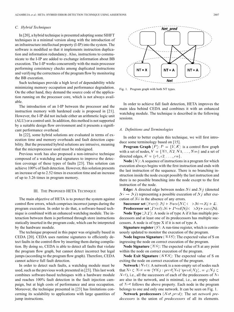
Fig. 1. Program graph with both NT types.
In order to achieve full fault detection, HETA improves themain idea behind CEDA and combines it with an enhancedwatchdog module. The technique is described in the followingsessions.
A. Definitions and Terminologies
In order to better explain this technique, we will first intro-duce some terminology based on [15].Program Graph : is a control flow graph
with a set of nodes, and a set ofdirected edges, .Node : A sequence of instructions in a program for which
execution always begins with the first instruction and ends withthe last instruction of the sequence. There is no branching in-struction inside the node except possibly the last instruction andthere is no possible branching into the node except to the firstinstruction of the node.Edge: A directed edge between nodes and (denoted
) representing a possible execution of after exe-cution of in the absence of any errors.Successor set :Predecessor set :Node Type : A node is of type A if it has multiple pre-
decessors and at least one of its predecessors has multiple suc-cessors. A node is of type X if it is not of type A.Signature register : A run-time register, which is contin-
uously updated to monitor the execution of the program.Node Ingress Signature : The expected value of S on
ingressing the node on correct execution of the program.Node Signature : The expected value of S at any point
within the node on correct execution of the program.Node Exit Signature : The expected value of S on
exiting the node on correct execution of the program.Network : A network is a non-empty set of nodes such
that :), i.e., all the successors of each of the predecessors of
are also in the network, and is minimal, i.e., an empty subsetof follows the above property. Each node in the programbelongs to one and only one network. It can be seen on Fig. 1.Network predecessors : The set network pre-
decessors is the union of predecessors of all its elements.
2808 IEEE TRANSACTIONS ON NUCLEAR SCIENCE, VOL. 60, NO. 4, AUGUST 2013
. It can be seenon Fig. 1.Related signature set : This set is the union of
of all the nodes in the network predecessors set and the ofall nodes of type A in the network.
B. Software-Side: Control-Flow Error Detection Novelties
HETA’s software-side technique can be divided in steps thatparse, analyze and add static instructions to the program code.The first step parses the program code and generates a programgraph, dividing the program into nodes and edges connectingthem. Each node represents a block of instructions that is al-ways executed sequentially, while the edges are the control flowbranches that interconnect them. On a second step, each node isanalyzed and receives an value, according to its incomingand outgoing edges. The third step assigns , andvalues to each node, according to some rules discussed later. Inthe final step, instructions are inserted into the original programcode.In the following subsections, the overall technique will be ex-
plained, as well as the algorithms used to choose the signaturesof the proposed technique.1) Overall Description: As mentioned before, HETA gener-
ates signatures based on a program graph representing the appli-cation control flow. Fig. 1. shows the generated program graphand the two types of nodes ( type A and type X). Asone can notice, the nodes where equals to A have multiplepredecessors and at least one of the predecessors has anothersuccessor. The node where equals to X has one single pre-decessor.Instructions are statically inserted into the program code to
continuously update the value of S during runtime, as to mon-itor the program flow. When the program execution reaches anew node, S is assigned with the node’s value. During itsexecution, the node’s value is assigned to S. When leavingthe node, S is assigned with the node’s value. and
values can detect control flow errors caused by jumps be-tween different nodes (internode errors). The value is re-sponsible for detecting control flow errors with incorrect jumpsinside the same node (intranode errors).At run-time, S can be updated up to three times in each node
transition. It varies because and , and also andvalues may be the same and, therefore, not require an up-
date on S. The updates on S follow the sequence: (1) to—when leaving a node, (2) to —when en-
tering a node, and (3) to —when executing a node.The updates 1 and 3 ( to and to , respec-tively) are a straight transformation based on the XOR operator,performed by the following instruction:
The update 2 ( to ), on the other hand, dependson the value of the current node. When equals to A,
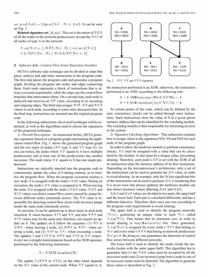
Fig. 2. , and signatures.
the instruction performed is an XOR; otherwise, the instructionperformed is an AND, according to the following rule:
At certain points of the code, which can be defined by theuser, consistency checks can be added through store instruc-tions. Such instructions store the value of S in a given presetmemory address that can be identified by the watchdog module.The watchdog module is then responsible for informing an errorto the system.2) Signature Checking Algorithms: This subsection explains
how to assign values to the signatures NIS, NS and NES for eachnode of the program graph.In order to allow the hardware module to perform consistency
checks, must be assigned with a value that can be calcu-lated by the module. It also must be a unique value, preventingaliasing. Therefore, each node’s is set with the XOR of allits instructions plus the memory address of its first instruction.Depending on the microprocessor’s architecture, only a set ofthe instructions can be used to generate the value, in orderto avoid aliasing. As an example, only the 16 less significant bitsof the instructions can be used to generate . Considering thatS is never reset, but always updated, the hardware module canalso detect incorrect values affecting and .
and values are divided in two parts, the upper halfand the lower half. Each part is calculated differently and has adifferent objective. Therefore, their sizes can vary according tothe program code requirements to avoid aliasing.The upper half is used to identify the program networks
, generating an unique value to each , called. That means that its minimum size, in order to
avoid aliasing is bits. Once generated,is assigned for every node’s that belong to
and every node’s that belong to network predecessor. By doing so, one guarantees the detection of control
flow errors between different networks.The lower half is used to identify the nodes inside the net-
works (nodes with the same upper half). This algorithm has toguarantee that (1) the value must be accepted by all thesuccessor nodes and (2) an incorrect jump from a node to one ofits successor nodes must be detected. The algorithm to generatethese values is described in Fig. 2.

AZAMBUJA et al.: HETA: HYBRID ERROR-DETECTION TECHNIQUE USING ASSERTIONS 2809
Fig. 3. Signature lower half algorithm.
Fig. 3. shows an example of the assignment of values to, and and the operations involved in the signa-
ture updating. The example shows only the lower half of thesignatures. The main idea of the technique is to allow a tran-sition from a node’s to its successor’s . The transitionfrom node A to node D, for example is quite easy, since ,
and are the same. In this case, only oneXOR operation is necessary, to transform into( xor 0111). The transition from node B to Eis a bit more complicated, since node B can also branch to nodeF. In this case, the differs from and .Because of this, two operations are required to transforminto ( xor 1101) and to transform
into ( xor 1110). Themost complex case is the transition from node B to node F,where all values are different. In this case, three transformationsare necessary, from to (xor 1101); from to (and 1100); and to (XOR 1000). It is important to mention that the transformation
to has to be performed with an AND becausenode E has .Another interesting fact about the above example is the
possible optimizations. If was equal to , atransformation would be removed, leading to performance gainand less program memory area. The same applies toand , and , and and
and . cannot have the same value as, because already has that value, and it would
lead to aliasing.The proposed technique, like CEDA, cannot detect incorrect
but legal jumps (according to the program graph). In order to dothat, another technique called Inverted Branches [7] is required.On the other hand, it detects intranode errors, which cannot beachieved by CEDA.
Fig. 4. Proposed architecture.
C. Hardware-Side: Enhanced Watchdog Module
The proposed approach based on hardware relies on a modulethat combines a watchdog with a decoder. The watchdog is usedto detect incorrect jumps to unused memory addresses and con-trol flow loops (which cannot be detected by software-basedtechniques), while the decoder reads data and address busesand the read/write signal between the microprocessor and thememory in order to perform the instructions sent by the soft-ware-based transformation rules. The decoder reads the busessearching for two instructions: (1) Reset XOR, which resets theinternal module’s register that store the current XOR value and(2) Check XOR, which performs a consistency check, by veri-fying the value in the data bus with the internal module’s reg-isters storing the current XOR value. Fig. 4 shows the overallarchitecture, with the hardware module connected to a micro-processor.The hardware module, besides having access to the memory
buses, must implement a XOR operator, a simple decodingmodule, which identifies instructions by monitoring the databus from the memory, and an error module to inform thesystem when an error is detected. The buses used by somemicroprocessors which use on-chip embedded cache memoriesmay not be accessible by the hardware module. In such cases,another approach should be used.
IV. SOFTWARE-BASED FAULT TOLERANCE TECHNIQUES
HETA alone cannot detect 100% faults in the control flowbecause it only detects errors that violate the control flow graph.An incorrect branch instruction that branches to a valid addresswill not be detected. Also, HETA has no mechanisms to detectdata-flow errors. This Section describes two techniques to copewith those cases.
A. Inverted Branches Technique
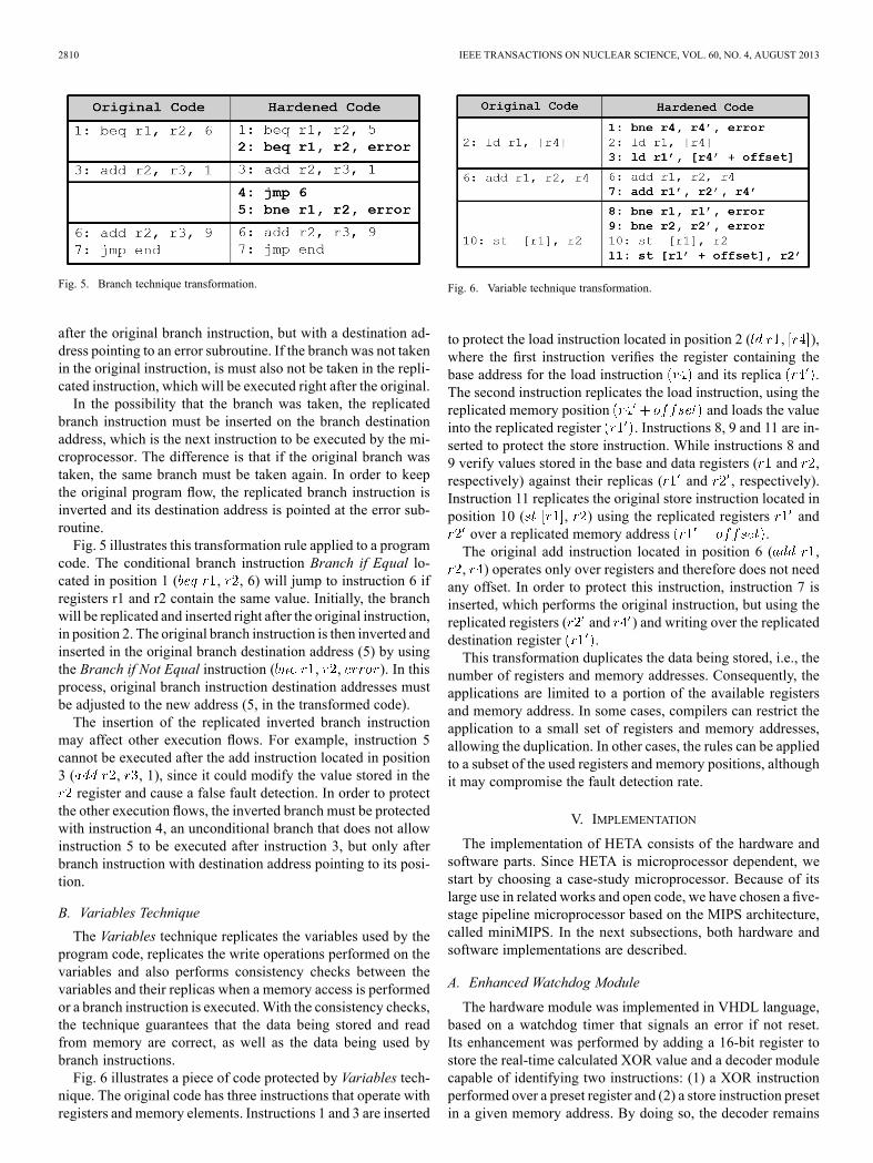
The inverted branch technique [7] was proposed to detectfaults affecting the decision of branch instructions. Such errorsaffect the transition between different BBs and are hard to be de-tected, since both paths (branch taken or not) are acceptable inthe program flow graph. A simple way of doing that is to repli-cate the branch instructions.Branch instructions are more difficult to replicate than non-
branch instructions, since they are not linear (they always havetwo possible next addresses). When the branch is not taken, abranch instruction can be simply replicated and inserted right
2810 IEEE TRANSACTIONS ON NUCLEAR SCIENCE, VOL. 60, NO. 4, AUGUST 2013
Fig. 5. Branch technique transformation.
after the original branch instruction, but with a destination ad-dress pointing to an error subroutine. If the branch was not takenin the original instruction, is must also not be taken in the repli-cated instruction, which will be executed right after the original.In the possibility that the branch was taken, the replicated
branch instruction must be inserted on the branch destinationaddress, which is the next instruction to be executed by the mi-croprocessor. The difference is that if the original branch wastaken, the same branch must be taken again. In order to keepthe original program flow, the replicated branch instruction isinverted and its destination address is pointed at the error sub-routine.Fig. 5 illustrates this transformation rule applied to a program
code. The conditional branch instruction Branch if Equal lo-cated in position 1 ( , , 6) will jump to instruction 6 ifregisters r1 and r2 contain the same value. Initially, the branchwill be replicated and inserted right after the original instruction,in position 2. The original branch instruction is then inverted andinserted in the original branch destination address (5) by usingthe Branch if Not Equal instruction ( , , ). In thisprocess, original branch instruction destination addresses mustbe adjusted to the new address (5, in the transformed code).The insertion of the replicated inverted branch instruction
may affect other execution flows. For example, instruction 5cannot be executed after the add instruction located in position3 ( , , 1), since it could modify the value stored in theregister and cause a false fault detection. In order to protect
the other execution flows, the inverted branch must be protectedwith instruction 4, an unconditional branch that does not allowinstruction 5 to be executed after instruction 3, but only afterbranch instruction with destination address pointing to its posi-tion.
B. Variables Technique
The Variables technique replicates the variables used by theprogram code, replicates the write operations performed on thevariables and also performs consistency checks between thevariables and their replicas when a memory access is performedor a branch instruction is executed.With the consistency checks,the technique guarantees that the data being stored and readfrom memory are correct, as well as the data being used bybranch instructions.Fig. 6 illustrates a piece of code protected by Variables tech-
nique. The original code has three instructions that operate withregisters and memory elements. Instructions 1 and 3 are inserted
Fig. 6. Variable technique transformation.
to protect the load instruction located in position 2 ( , ),where the first instruction verifies the register containing thebase address for the load instruction and its replica .The second instruction replicates the load instruction, using thereplicated memory position and loads the valueinto the replicated register . Instructions 8, 9 and 11 are in-serted to protect the store instruction. While instructions 8 and9 verify values stored in the base and data registers ( and ,respectively) against their replicas ( and , respectively).Instruction 11 replicates the original store instruction located inposition 10 ( , ) using the replicated registers andover a replicated memory address .The original add instruction located in position 6 ( ,, ) operates only over registers and therefore does not need
any offset. In order to protect this instruction, instruction 7 isinserted, which performs the original instruction, but using thereplicated registers ( and ) and writing over the replicateddestination register .This transformation duplicates the data being stored, i.e., the
number of registers and memory addresses. Consequently, theapplications are limited to a portion of the available registersand memory address. In some cases, compilers can restrict theapplication to a small set of registers and memory addresses,allowing the duplication. In other cases, the rules can be appliedto a subset of the used registers and memory positions, althoughit may compromise the fault detection rate.
V. IMPLEMENTATION
The implementation of HETA consists of the hardware andsoftware parts. Since HETA is microprocessor dependent, westart by choosing a case-study microprocessor. Because of itslarge use in related works and open code, we have chosen a five-stage pipeline microprocessor based on the MIPS architecture,called miniMIPS. In the next subsections, both hardware andsoftware implementations are described.
A. Enhanced Watchdog Module
The hardware module was implemented in VHDL language,based on a watchdog timer that signals an error if not reset.Its enhancement was performed by adding a 16-bit register tostore the real-time calculated XOR value and a decoder modulecapable of identifying two instructions: (1) a XOR instructionperformed over a preset register and (2) a store instruction presetin a given memory address. By doing so, the decoder remains
AZAMBUJA et al.: HETA: HYBRID ERROR-DETECTION TECHNIQUE USING ASSERTIONS 2811
TABLE IORIGINAL AND MODIFIED ARCHITECTURE CHARACTERISTICS
Fig. 7. HETA’s software-side program transformation.
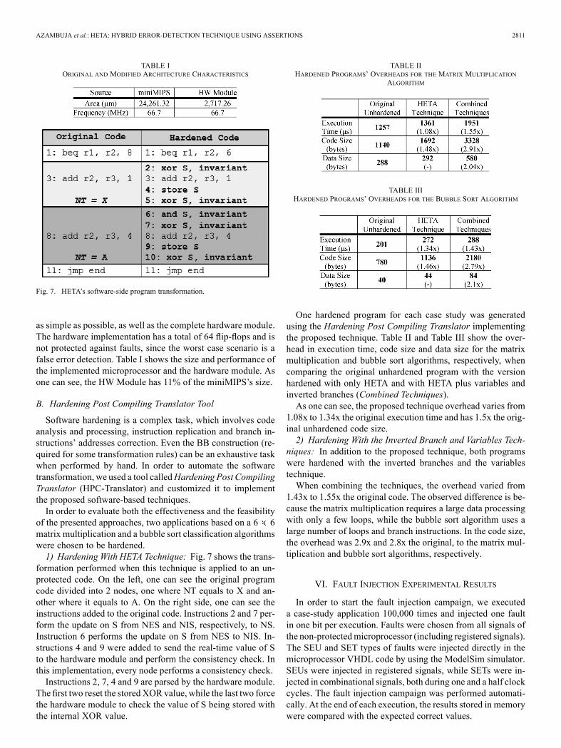
as simple as possible, as well as the complete hardware module.The hardware implementation has a total of 64 flip-flops and isnot protected against faults, since the worst case scenario is afalse error detection. Table I shows the size and performance ofthe implemented microprocessor and the hardware module. Asone can see, the HW Module has 11% of the miniMIPS’s size.
B. Hardening Post Compiling Translator Tool
Software hardening is a complex task, which involves codeanalysis and processing, instruction replication and branch in-structions’ addresses correction. Even the BB construction (re-quired for some transformation rules) can be an exhaustive taskwhen performed by hand. In order to automate the softwaretransformation, we used a tool calledHardening Post CompilingTranslator (HPC-Translator) and customized it to implementthe proposed software-based techniques.In order to evaluate both the effectiveness and the feasibility
of the presented approaches, two applications based on a 6 6matrix multiplication and a bubble sort classification algorithmswere chosen to be hardened.1) Hardening With HETA Technique: Fig. 7 shows the trans-
formation performed when this technique is applied to an un-protected code. On the left, one can see the original programcode divided into 2 nodes, one where NT equals to X and an-other where it equals to A. On the right side, one can see theinstructions added to the original code. Instructions 2 and 7 per-form the update on S from NES and NIS, respectively, to NS.Instruction 6 performs the update on S from NES to NIS. In-structions 4 and 9 were added to send the real-time value of Sto the hardware module and perform the consistency check. Inthis implementation, every node performs a consistency check.Instructions 2, 7, 4 and 9 are parsed by the hardware module.
The first two reset the stored XOR value, while the last two forcethe hardware module to check the value of S being stored withthe internal XOR value.
TABLE IIHARDENED PROGRAMS’ OVERHEADS FOR THE MATRIX MULTIPLICATION
ALGORITHM
TABLE IIIHARDENED PROGRAMS’ OVERHEADS FOR THE BUBBLE SORT ALGORITHM
One hardened program for each case study was generatedusing the Hardening Post Compiling Translator implementingthe proposed technique. Table II and Table III show the over-head in execution time, code size and data size for the matrixmultiplication and bubble sort algorithms, respectively, whencomparing the original unhardened program with the versionhardened with only HETA and with HETA plus variables andinverted branches (Combined Techniques).As one can see, the proposed technique overhead varies from
1.08x to 1.34x the original execution time and has 1.5x the orig-inal unhardened code size.2) Hardening With the Inverted Branch and Variables Tech-
niques: In addition to the proposed technique, both programswere hardened with the inverted branches and the variablestechnique.When combining the techniques, the overhead varied from
1.43x to 1.55x the original code. The observed difference is be-cause the matrix multiplication requires a large data processingwith only a few loops, while the bubble sort algorithm uses alarge number of loops and branch instructions. In the code size,the overhead was 2.9x and 2.8x the original, to the matrix mul-tiplication and bubble sort algorithms, respectively.
VI. FAULT INJECTION EXPERIMENTAL RESULTS
In order to start the fault injection campaign, we executeda case-study application 100,000 times and injected one faultin one bit per execution. Faults were chosen from all signals ofthe non-protectedmicroprocessor (including registered signals).The SEU and SET types of faults were injected directly in themicroprocessor VHDL code by using the ModelSim simulator.SEUs were injected in registered signals, while SETs were in-jected in combinational signals, both during one and a half clockcycles. The fault injection campaign was performed automati-cally. At the end of each execution, the results stored in memorywere compared with the expected correct values.

2812 IEEE TRANSACTIONS ON NUCLEAR SCIENCE, VOL. 60, NO. 4, AUGUST 2013
TABLE IVFAULT INJECTION RESULTS
The experiment continuously compared the Program Counter(PC) of a goldenmicroprocessor with the PC of the faulty micro-processor and the generated data results. Fault injection resultsare presented in Table IV. It shows the number of injected faults(Faults Injected) for each application, the number of faults thatcaused an error in the microprocessor (Incorrect Result) and thedetection rate achieved by the proposed solution (Errors De-tected). The system was simulated with a clock period of 42 nsand a total of 2459 signals describing it. To prove the effective-ness of the proposed technique, we also injected 100,000 faultsin the PC for the bubble sort application. It represents around 21times the total number of clock cycles that the microprocessortakes to run the application. The result was 100% fault detec-tion.
VII. CONCLUSIONS AND FUTURE WORK
In this paper, the authors presented a non-intrusive hybridtechnique based on signatures and an enhanced watchdogmodule. Then, a tool was used to automatically harden binaryprograms. A fault injection campaign based on simulation wasperformed on the implemented techniques. Results showedthat the proposed techniques could achieve full fault detectionagainst control flow errors with performance degradation up to1.55x and area overhead of 11%.We are currently working on decreasing the impact on execu-
tion time andmemory overhead of the proposed technique whilekeeping the same fault detection rates. As future work, we alsointend to verify the feasibility and effectiveness of the proposedtechniques applied to a real time operating system.
REFERENCES
[1] R. C. Baumann, “Soft errors in advanced semiconductor devices-partI: The three radiation sources,” IEEE Trans. Device Mater. Rel., vol.1, no. 1, pp. 17–22, Mar. 2001.
[2] International Technology Roadmap for Semiconductors: 2005 EditionChapter Design, 2005, pp. 6–7.
[3] P. E. Dodd and L. W. Massengill, “Basic mechanism and modeling ofsingle-event upset in digital microelectronics,” IEEE Trans. Nucl. Sci.,vol. 50, no. 3, pp. 583–602, Jun. 2003.
[4] O. Goloubeva, M. Rebaudengo, M. Sonza Reorda, and M. Violante,“Soft-error detection using control flow assertions,” presented at theIEEE Int. Symp. Defect and Fault Tolerance in VLSI Systems, 2003.
[5] N. Oh, P. P. Shirvani, and E. J. McCluskey, “Control flow checkingby software signatures,” IEEE Trans. Reliability, vol. 51, no. 2, pp.111–112, May 2002.
[6] C. Bolchini, A. Miele, F. Salice, and D. Sciuto, “A model of soft erroreffects in generic ip processors,” presented at the IEEE Int. Symp. De-fect and Fault Tolerance in VLSI Systems, 2005.
[7] J. R. Azambuja, S. Pagliarini, L. Rosa, and F. L. Kastensmidt, “Ex-ploring the limitations of software-only techniques in SEE detectioncoverage,” J. Electron. Test., no. 27, pp. 541–550, 2011.
[8] A. Mahmood and E. McCluskey, “Concurrent error detection usingwatchdog processors,” IEEE Trans. Comput., 1988.
[9] E. Rhod, C. Lisboa, L. Carro, M. S. Reorda, and M. Violante, “Hard-ware and software transparency in the protection of programs againstSEUs and SETs,” J. Electron. Test., no. 24, pp. 45–56, 2008.
[10] C. Bolchini, L. Pomante, F. Salice, and D. Sciuto, “Reliable systemspecification for self-checking datapaths,” presented at the Conf. onDesign, Automation and Test in Europe, 2005.
[11] R. Vemu, S. Gurumurthy, and J. A. Abraham, “ACCE: Automatic cor-rection of control-flow errors,” presented at the IEEE International TestConference, 2007.
[12] N. Oh, P. P. Shirvani, and E. J. McCluskey, “Control-flow checkingby software signatures,” IEEE Trans. Reliability, vol. 51, no. 1, pp.111–122, Mar. 2002.
[13] L. D. Mcfearin and V. S. S. Nair, “Control-flow checking using asser-tions,” presented at the IFIP International Working Conf. DependableComputing for Critical Applications, 1995.
[14] Z. Alkhalifa, V. S. S. Nair, N. Krishnamurthy, and J. A. Abraham,“Design and evaluation of system-level checks for on-line control flowerror detection,” IEEE Trans. Parallel Distrib. Syst., vol. 10, no. 6, pp.627–641, Jun. 1999.
[15] R. Vemu and J. Abraham, “CEDA: Control-flow error detectionthrough assertions,” presented at the IEEE Int. On-line Testing Symp.,2006.
[16] B. Nicolescu and R. Velazco, “Detecting soft errors by a purely soft-ware approach: Method, tools and experimental results,” presented atthe Design, Automation and Test in Europe Conf. Exhibition, 2003.
[17] M. Namjoo and E. J. McCluskey, “Watchdog processors and capabilitychecking,” presented at the Int. Symp. on Fault Tolerant Computing,1982.
[18] A. Mahmood, D. J. Lu, and E. J. McCluskey, “Concurrent fault detec-tion using a watchdog processor and assertions,” presented at the IEEEInternational Test Conf., 1983.
[19] J. Ohlsson and M. Rimen, “Implicit signature checking,” presented atthe Dig. Papers of the Int. Symp. on Fault Tolerant Computing, 1995.
[20] P. Bernardi, L. M. V. Bolzani, M. Rebaudengo, M. S. Reorda, F. L.Vargas, and M. Violante, “A new hybrid fault detection techniquefor systems-on-a-chip,” IEEE Trans. Computers, vol. 55, no. 2, pp.185–198, 2006.
[21] M. Schillaci, M. S. Reorda, and M. Violante, “A new approach to copewith single event upsets in processor-based systems,” presented at theIEEE Latin-American Test Workshop, 2006.
[22] S. Cuenca-Asensi, A. Martinez-Alvarez, F. Restrepo-Calle, F. Palomo,H. Guzman-Miranda, andM. Aguirre, “A novel co-design approach forsoft errors mitigation in embedded systems,” IEEE Trans. Nucl. Sci.,to be published.
[23] J. R. Azambuja, A. Lapolli, L. Rosa, and F. L. Kastensmidt, “DetectingSEEs in microprocessors through a non-intrusive hybrid technique,”IEEE Trans. Nucl. Sci., to be published.