Embed Size (px)
Citation preview
LESSON 9
Hertz Contact Problem
Objectives:
■ Use of contact pair approach
■ Multi-step analysis
■ Post-processing of the results
PATRAN 322 Exercise Workbook 9-1

9-2 PATRAN 322 Exercise Workbook
LESSON 9 Hertz Contact Problem
ret
s
t
h
e.
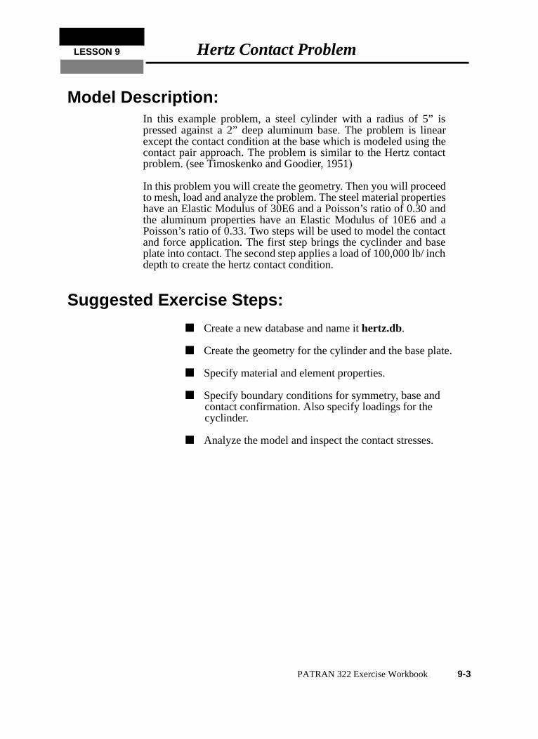
Model Description:In this example problem, a steel cylinder with a radius of 5” ispressed against a 2” deep aluminum base. The problem is lineaexcept the contact condition at the base which is modeled using thcontact pair approach. The problem is similar to the Hertz contacproblem. (see Timoskenko and Goodier, 1951)
In this problem you will create the geometry. Then you will proceedto mesh, load and analyze the problem. The steel material propertiehave an Elastic Modulus of 30E6 and a Poisson’s ratio of 0.30 andthe aluminum properties have an Elastic Modulus of 10E6 and aPoisson’s ratio of 0.33. Two steps will be used to model the contacand force application. The first step brings the cyclinder and baseplate into contact. The second step applies a load of 100,000 lb/ incdepth to create the hertz contact condition.
Suggested Exercise Steps:
■ Create a new database and name it hertz.db.
■ Create the geometry for the cylinder and the base plat
■ Specify material and element properties.
■ Specify boundary conditions for symmetry, base and contact confirmation. Also specify loadings for the cyclinder.
■ Analyze the model and inspect the contact stresses.
PATRAN 322 Exercise Workbook 9-3
Exercise Procedure:1. Open a new database. Name it hertz.
Change the New Analysis Preference form to MSC⁄ADVANCED_FEA.
2. Create the geometry for the cylinder and the base plate.
First create a group that contains the cylinder and name it cylinder
File/New ...
Database Name: hertz.db
OK
Analysis Code: MSC/ADVANCED_FEA
OK
Group/Create...
New Group Name: cylinder
■ Make Current
Group Contents: Add Entity Selection
Apply
Cancel
◆ Geometry
Action: Create
Object: Curve
Method: XYZ
Vector Coordinates List: <5, 0, 0>
Origin Coordinates List: [0, 0, 0]
Apply
Action: Create
Object: Surface
Method: Revolve
9-4 PATRAN 322 Exercise Workbook
LESSON 9 Hertz Contact Problem
Now create a group for the base plate.
3. Post cylinder geometry.
Post only the geometry for the cylinder.
■ Patran 2 Convention
Axis: Coord 0.3
Total Angle: -180
Surfaces per Curve: 2
Curve List: Curve 1
Apply
Group/Create...
New Group Name: plate
■ Make Current
Group Contents: Add Entity Selection
Apply
Cancel
◆ Geometry
Action: Create
Object: Surface
Method: XYZ
Vector Coordinates List: <16, -2, 0>
Origin Coordinates List: [-8, -5.1, 0]
Apply
Group/Post...
Select Groups to Post: cylinder
Apply
PATRAN 322 Exercise Workbook 9-5
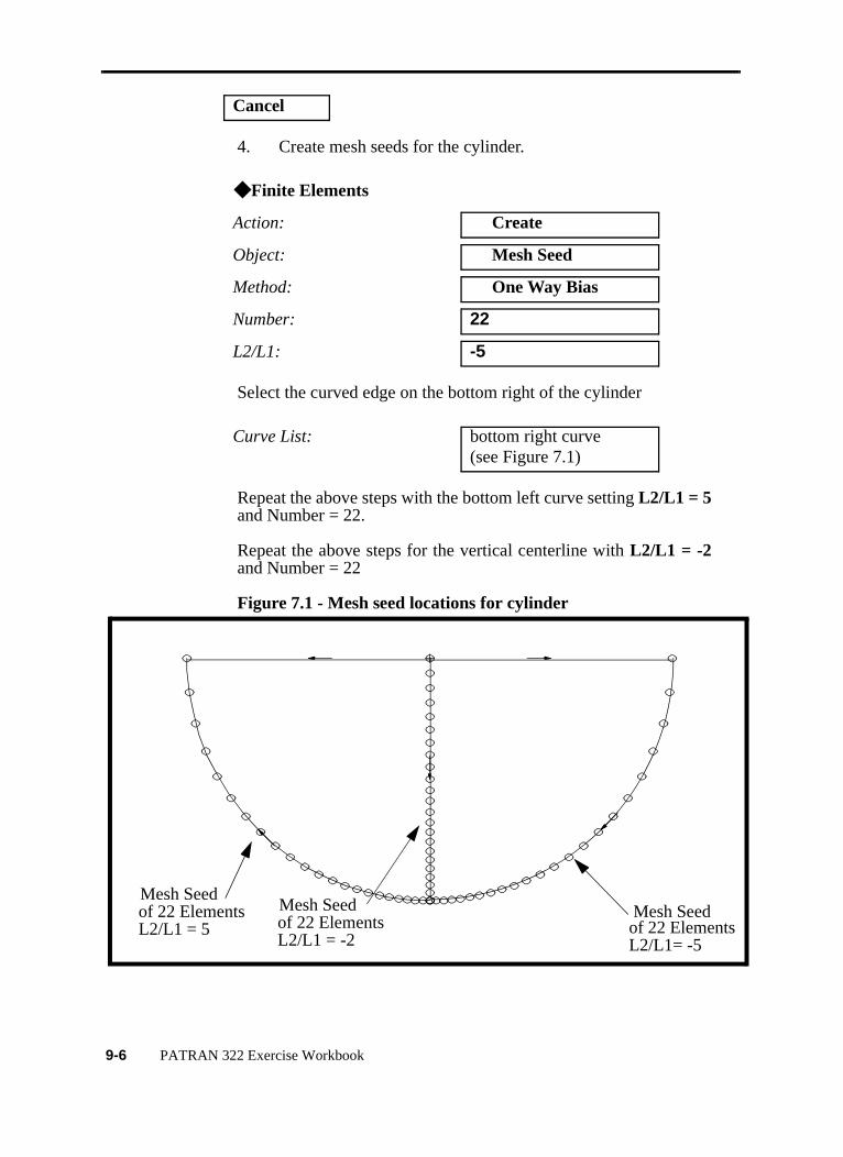
4. Create mesh seeds for the cylinder.
Select the curved edge on the bottom right of the cylinder
Repeat the above steps with the bottom left curve setting L2/L1 = 5and Number = 22.
Repeat the above steps for the vertical centerline with L2/L1 = -2and Number = 22
Figure 7.1 - Mesh seed locations for cylinder
Cancel
◆ Finite Elements
Action: Create
Object: Mesh Seed
Method: One Way Bias
Number: 22
L2/L1: -5
Curve List: bottom right curve(see Figure 7.1)
Mesh Seed of 22 ElementsL2/L1= -5
Mesh Seed of 22 ElementsL2/L1 = 5
Mesh Seed of 22 ElementsL2/L1 = -2
9-6 PATRAN 322 Exercise Workbook
LESSON 9 Hertz Contact Problem
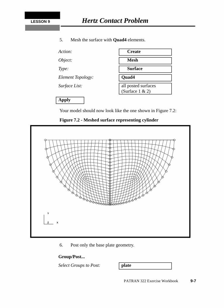
5. Mesh the surface with Quad4 elements.
Your model should now look like the one shown in Figure 7.2:
Figure 7.2 - Meshed surface representing cylinder
6. Post only the base plate geometry.
Action: Create
Object: Mesh
Type: Surface
Element Topology: Quad4
Surface List: all posted surfaces(Surface 1 & 2)
Apply
Group/Post...
Select Groups to Post: plate
X
Y
Z X
Y
Z
PATRAN 322 Exercise Workbook 9-7
M1oo
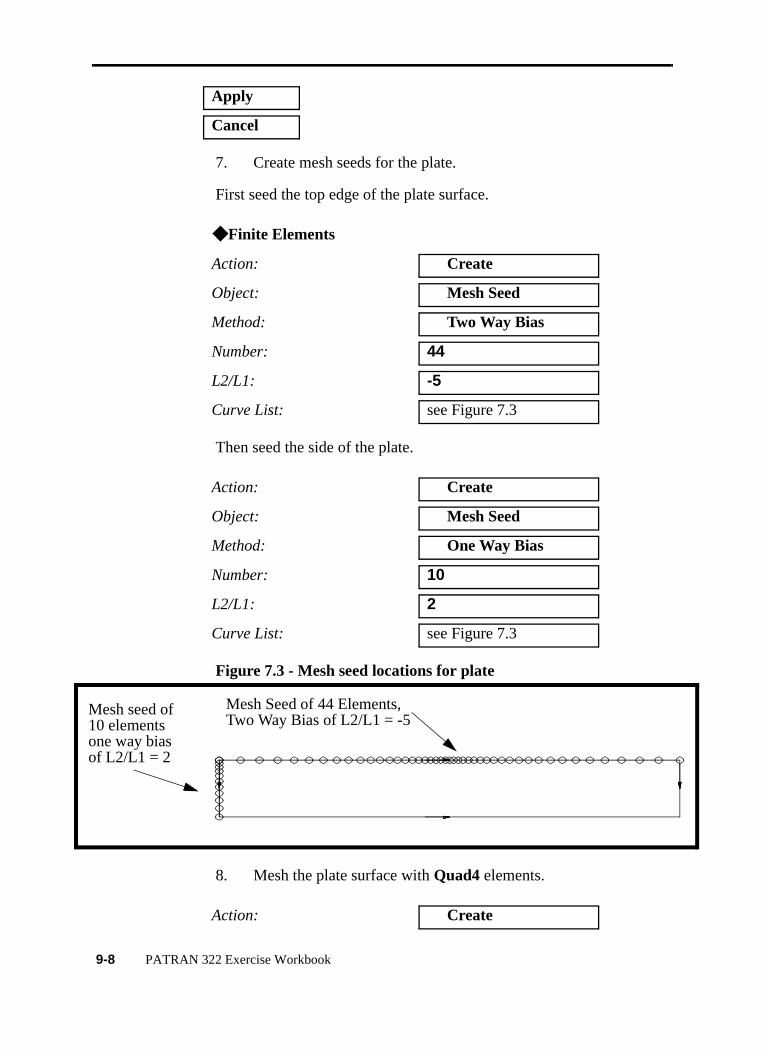
7. Create mesh seeds for the plate.
First seed the top edge of the plate surface.
Then seed the side of the plate.
Figure 7.3 - Mesh seed locations for plate
8. Mesh the plate surface with Quad4 elements.
Apply
Cancel
◆ Finite Elements
Action: Create
Object: Mesh Seed
Method: Two Way Bias
Number: 44
L2/L1: -5
Curve List: see Figure 7.3
Action: Create
Object: Mesh Seed
Method: One Way Bias
Number: 10
L2/L1: 2
Curve List: see Figure 7.3
Action: Create
Mesh Seed of 44 Elements,Two Way Bias of L2/L1 = -5
esh seed of0 elementsne way biasf L2/L1 = 2
9-8 PATRAN 322 Exercise Workbook
LESSON 9 Hertz Contact Problem
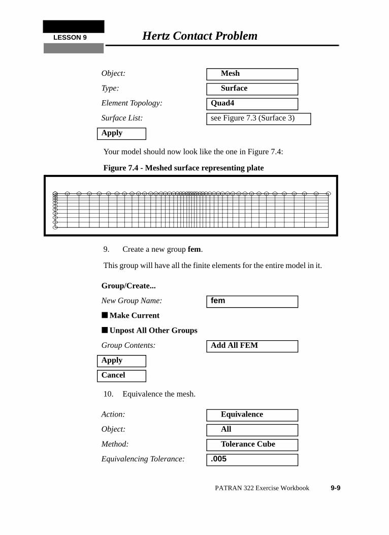
Your model should now look like the one in Figure 7.4:
Figure 7.4 - Meshed surface representing plate
9. Create a new group fem.
This group will have all the finite elements for the entire model in it.
10. Equivalence the mesh.
Object: Mesh
Type: Surface
Element Topology: Quad4
Surface List: see Figure 7.3 (Surface 3)
Apply
Group/Create...
New Group Name: fem
■ Make Current
■ Unpost All Other Groups
Group Contents: Add All FEM
Apply
Cancel
Action: Equivalence
Object: All
Method: Tolerance Cube
Equivalencing Tolerance: .005
PATRAN 322 Exercise Workbook 9-9
11. Verify element normals.
Since this is a 2-D plane strain model, the normals will need to bepointing in the positive Z direction. To assist you in reversingelement normals, we will display the element normals right on theelements.
You will need to turn the model to see that the vectors are in thepositive direction.
To quickly turn your model, select the following toolbar icon.
Also, it is helpful to change the model to Hidden Line render style,using the following toolbar icon.
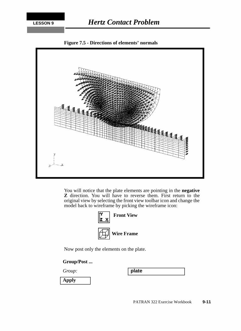
Your model should look like the figure shown in Figure 7.5:
Apply
Action: Verify
Object: Element
Test: Normals
◆ Draw Normal Vectors
Apply
Iso 1 View
Hidden Line
9-10 PATRAN 322 Exercise Workbook
LESSON 9 Hertz Contact Problem
Figure 7.5 - Directions of elements’ normals
You will notice that the plate elements are pointing in the negativeZ direction. You will have to reverse them. First return to theoriginal view by selecting the front view toolbar icon and change themodel back to wireframe by picking the wireframe icon:
Now post only the elements on the plate.
Group/Post ...
Group: plate
Apply
Front View
Wire Frame
PATRAN 322 Exercise Workbook 9-11
e
Reset the graphics display by selecting the Reset Graphics icon.
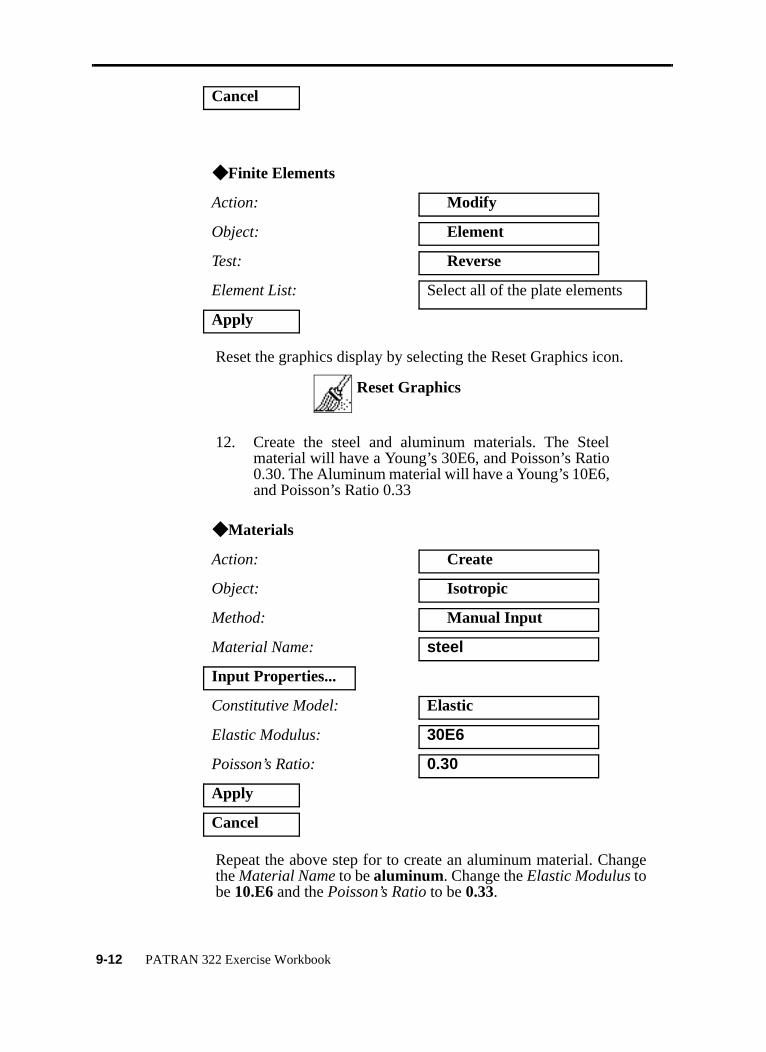
12. Create the steel and aluminum materials. The Steelmaterial will have a Young’s 30E6, and Poisson’s Ratio0.30. The Aluminum material will have a Young’s 10E6,and Poisson’s Ratio 0.33
Repeat the above step for to create an aluminum material. Changthe Material Name to be aluminum. Change the Elastic Modulus tobe 10.E6 and the Poisson’s Ratio to be 0.33.
Cancel
◆ Finite Elements
Action: Modify
Object: Element
Test: Reverse
Element List: Select all of the plate elements
Apply
◆ Materials
Action: Create
Object: Isotropic
Method: Manual Input
Material Name: steel
Input Properties...
Constitutive Model: Elastic
Elastic Modulus: 30E6
Poisson’s Ratio: 0.30
Apply
Cancel
Reset Graphics
9-12 PATRAN 322 Exercise Workbook
LESSON 9 Hertz Contact Problem
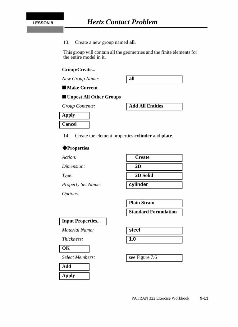
13. Create a new group named all.
This group will contain all the geometries and the finite elements forthe entire model in it.
14. Create the element properties cylinder and plate.
Group/Create...
New Group Name: all
■ Make Current
■ Unpost All Other Groups
Group Contents: Add All Entities
Apply
Cancel
◆ Properties
Action: Create
Dimension: 2D
Type: 2D Solid
Property Set Name: cylinder
Options:
Plain Strain
Standard Formulation
Input Properties...
Material Name: steel
Thickness: 1.0
OK
Select Members: see Figure 7.6
Add
Apply
PATRAN 322 Exercise Workbook 9-13
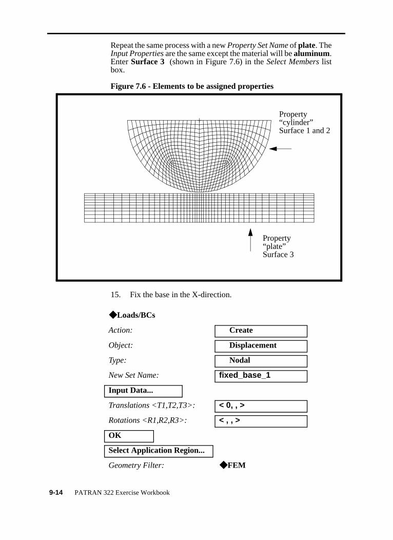
Repeat the same process with a new Property Set Name of plate. TheInput Properties are the same except the material will be aluminum.Enter Surface 3 (shown in Figure 7.6) in the Select Members listbox.
Figure 7.6 - Elements to be assigned properties
15. Fix the base in the X-direction.
◆ Loads/BCs
Action: Create
Object: Displacement
Type: Nodal
New Set Name: fixed_base_1
Input Data...
Translations <T1,T2,T3>: < 0, , >
Rotations <R1,R2,R3>: < , , >
OK
Select Application Region...
Geometry Filter: ◆ FEM
Property“cylinder”Surface 1 and 2
Property“plate”Surface 3
9-14 PATRAN 322 Exercise Workbook
LESSON 9 Hertz Contact Problem
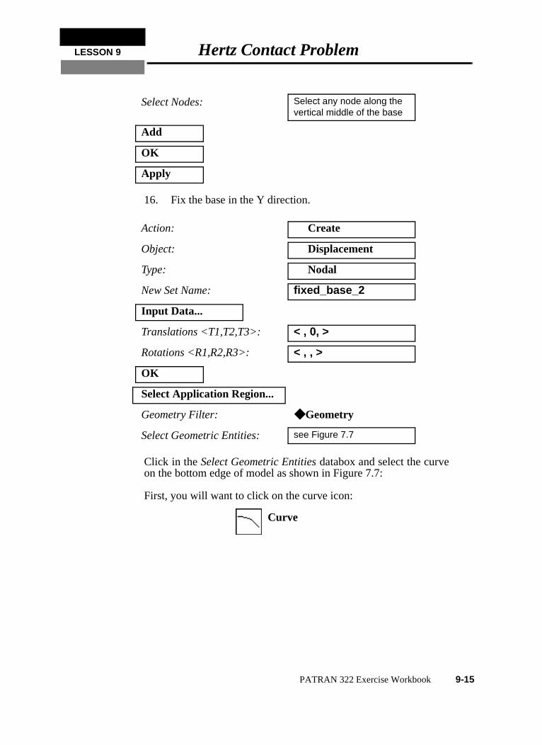
16. Fix the base in the Y direction.
Click in the Select Geometric Entities databox and select the curveon the bottom edge of model as shown in Figure 7.7:
First, you will want to click on the curve icon:
Select Nodes: Select any node along the vertical middle of the base
Add
OK
Apply
Action: Create
Object: Displacement
Type: Nodal
New Set Name: fixed_base_2
Input Data...
Translations <T1,T2,T3>: < , 0, >
Rotations <R1,R2,R3>: < , , >
OK
Select Application Region...
Geometry Filter: ◆ Geometry
Select Geometric Entities: see Figure 7.7
Curve
PATRAN 322 Exercise Workbook 9-15
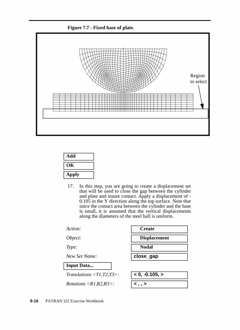
Figure 7.7 - Fixed base of plate.
17. In this step, you are going to create a displacement setthat will be used to close the gap between the cylinderand plate and insure contact. Apply a displacement of -0.105 in the Y direction along the top surface. Note thatsince the contact area between the cylinder and the baseis small, it is assumed that the vertical displacementsalong the diameters of the steel ball is uniform.
Add
OK
Apply
Action: Create
Object: Displacement
Type: Nodal
New Set Name: close_gap
Input Data...
Translations <T1,T2,T3>: < 0, -0.105, >
Rotations <R1,R2,R3>: < , , >
Regionto select
9-16 PATRAN 322 Exercise Workbook
LESSON 9 Hertz Contact Problem
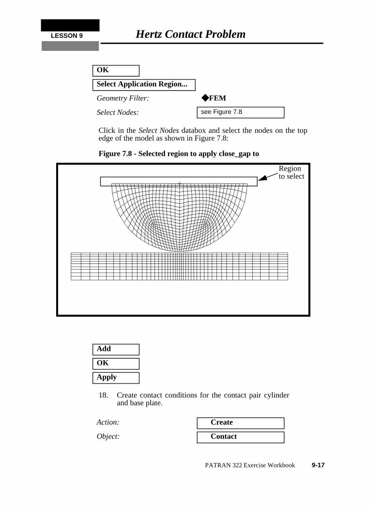
Click in the Select Nodes databox and select the nodes on the topedge of the model as shown in Figure 7.8:
Figure 7.8 - Selected region to apply close_gap to
18. Create contact conditions for the contact pair cylinderand base plate.
OK
Select Application Region...
Geometry Filter: ◆ FEM
Select Nodes: see Figure 7.8
Add
OK
Apply
Action: Create
Object: Contact
Regionto select
PATRAN 322 Exercise Workbook 9-17
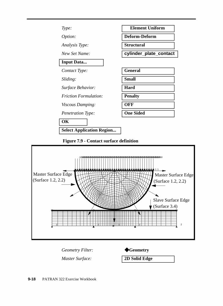
Figure 7.9 - Contact surface definition
Type: Element Uniform
Option: Deform-Deform
Analysis Type: Structural
New Set Name: cylinder_plate_contact
Input Data...
Contact Type: General
Sliding: Small
Surface Behavior: Hard
Friction Formulation: Penalty
Viscous Damping: OFF
Penetration Type: One Sided
OK
Select Application Region...
Geometry Filter: ◆ Geometry
Master Surface: 2D Solid Edge
2 2 2 2
1
.1050
1
.1050
1
.1050
1
.1050
1
.1050
1
.1050
1
.1050
1
.1050
1
.1050
1
.1050
1
.1050
1
.1050
1
.1050
1
.1050
1
.1050
1
.1050
1
.1050
1
.1050
1
.1050
1
.1050
1
.1050
1
.1050
1
.1050
1
.1050
1
.1050
1
.1050
1
.1050
1
.1050
1
.1050
1
.1050
1
.1050
1
.1050
1
.1050
1
.1050
1
.1050
1
.1050
1
.1050
1
Master Surface EdgeMaster Surface Edge
Slave Surface Edge
(Surface 1.2, 2.2) (Surface 1.2, 2.2)
(Surface 3.4)
9-18 PATRAN 322 Exercise Workbook
LESSON 9 Hertz Contact Problem
19. The final Load and Boundary Condition will be theapplied pressure at the top of the cyclinder. We willsimulate a load of 100,000 lb per unit depth across theentire cyclinder. The applied edge pressure will besimply the load per unit depth divided by the diameter,or 100,000/10.0 = 10,000 psi pressure.
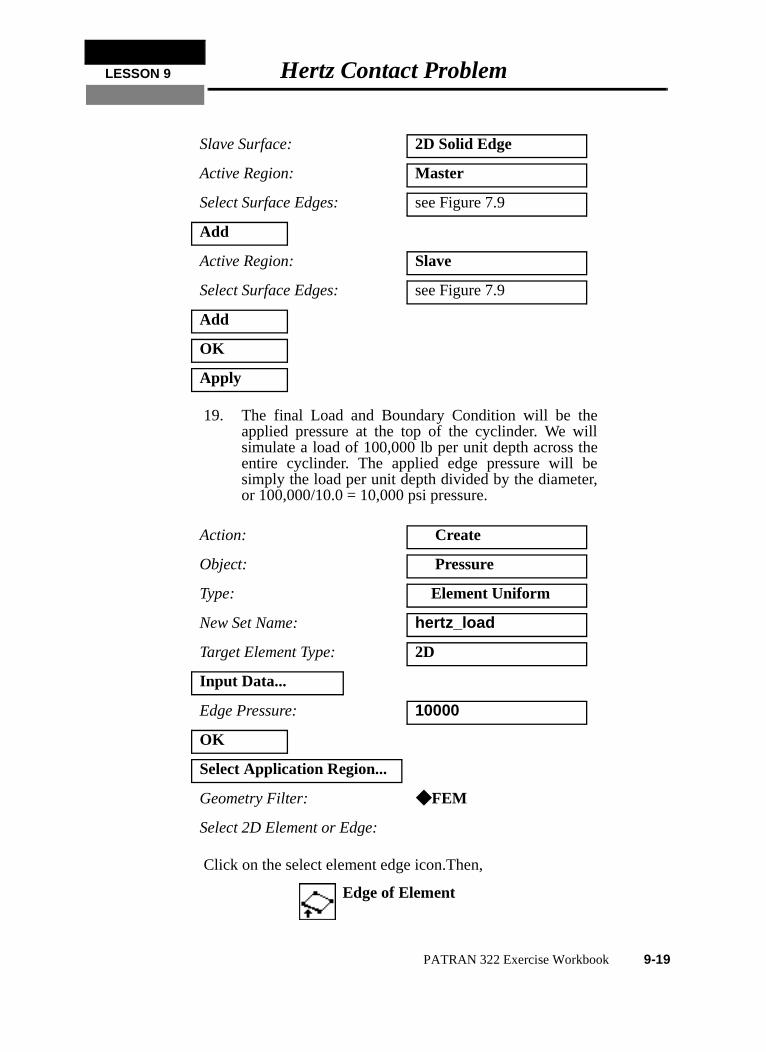
Click on the select element edge icon.Then,
Slave Surface: 2D Solid Edge
Active Region: Master
Select Surface Edges: see Figure 7.9
Add
Active Region: Slave
Select Surface Edges: see Figure 7.9
Add
OK
Apply
Action: Create
Object: Pressure
Type: Element Uniform
New Set Name: hertz_load
Target Element Type: 2D
Input Data...
Edge Pressure: 10000
OK
Select Application Region...
Geometry Filter: ◆ FEM
Select 2D Element or Edge:
Edge of Element
PATRAN 322 Exercise Workbook 9-19
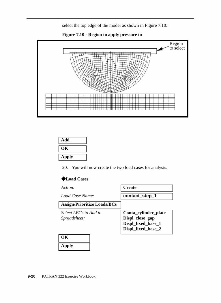
select the top edge of the model as shown in Figure 7.10:
Figure 7.10 - Region to apply pressure to
20. You will now create the two load cases for analysis.
Add
OK
Apply
◆ Load Cases
Action: Create
Load Case Name: contact_step_1
Assign/Prioritize Loads/BCs
Select LBCs to Add to Spreadsheet:
Conta_cylinder_plateDispl_close_gapDispl_fixed_base_1Displ_fixed_base_2
OK
Apply
Regionto select
9-20 PATRAN 322 Exercise Workbook
LESSON 9 Hertz Contact Problem
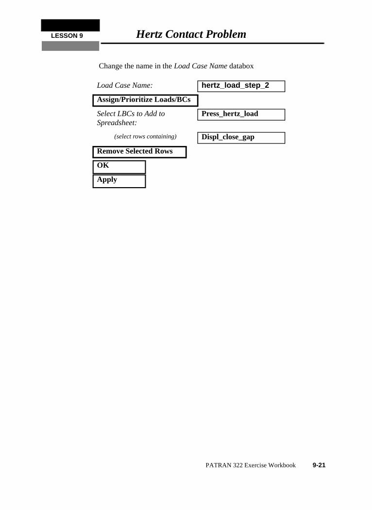
Change the name in the Load Case Name databox
Load Case Name: hertz_load_step_2
Assign/Prioritize Loads/BCs
Select LBCs to Add to Spreadsheet:
Press_hertz_load
(select rows containing) Displ_close_gap
Remove Selected Rows
OK
Apply
PATRAN 322 Exercise Workbook 9-21
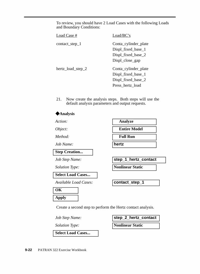
To review, you should have 2 Load Cases with the following Loadsand Boundary Conditions:
Load Case # Load/BC’s
contact_step_1 Conta_cylinder_plateDispl_fixed_base_1Displ_fixed_base_2Displ_close_gap
hertz_load_step_2 Conta_cylinder_plateDispl_fixed_base_1Displ_fixed_base_2Press_hertz_load
21. Now create the analysis steps. Both steps will use thedefault analysis parameters and output requests.
Create a second step to perform the Hertz contact analysis.
◆ Analysis
Action: Analyze
Object: Entire Model
Method: Full Run
Job Name: hertz
Step Creation...
Job Step Name: step_1_hertz_contact
Solution Type: Nonlinear Static
Select Load Cases...
Available Load Cases: contact_step_1
OK
Apply
Job Step Name: step_2_hertz_contact
Solution Type: Nonlinear Static
Select Load Cases...
9-22 PATRAN 322 Exercise Workbook
LESSON 9 Hertz Contact Problem
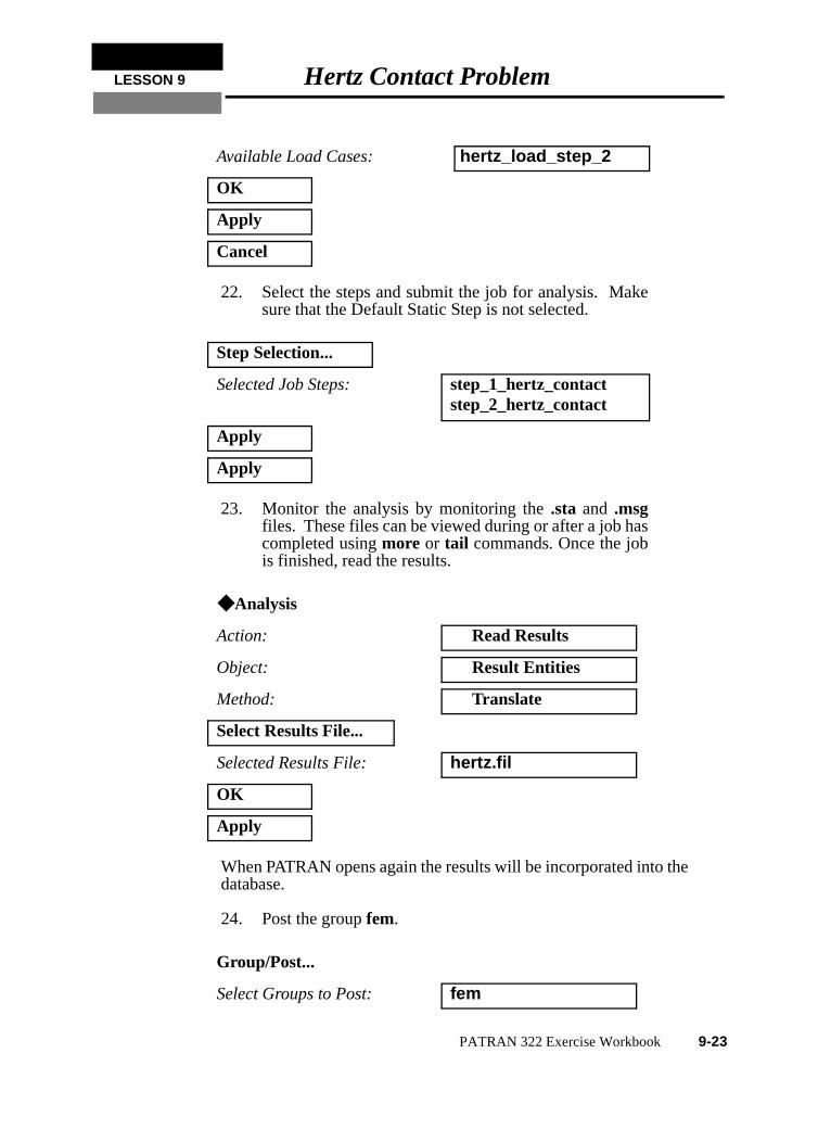
22. Select the steps and submit the job for analysis. Makesure that the Default Static Step is not selected.
23. Monitor the analysis by monitoring the .sta and .msgfiles. These files can be viewed during or after a job hascompleted using more or tail commands. Once the jobis finished, read the results.
When PATRAN opens again the results will be incorporated into thedatabase.
24. Post the group fem.
Available Load Cases: hertz_load_step_2
OK
Apply
Cancel
Step Selection...
Selected Job Steps: step_1_hertz_contactstep_2_hertz_contact
Apply
Apply
◆ Analysis
Action: Read Results
Object: Result Entities
Method: Translate
Select Results File...
Selected Results File: hertz.fil
OK
Apply
Group/Post...
Select Groups to Post: fem
PATRAN 322 Exercise Workbook 9-23
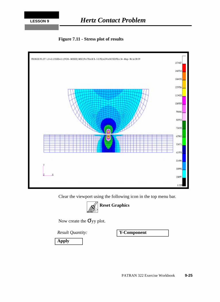
25. Make fringe plots of Von Mises, σyy and σxy.
Click on Select Results
Your model should appear as shown in Figure 7.11:
Apply
Cancel
◆ Results
Action: Create
Object: Quick Plot
Select Results Cases: select the last load case
Select Fringe Result: Stress,Components
Result Quantity: Von Mises
Apply
9-24 PATRAN 322 Exercise Workbook
LESSON 9 Hertz Contact Problem
Figure 7.11 - Stress plot of results
Clear the viewport using the following icon in the top menu bar.
Now create the σyy plot.
Result Quantity: Y-Component
Apply
Reset Graphics
PATRAN 322 Exercise Workbook 9-25
Clear the viewport using the following icon in the top menu bar.
Finally, use the above procedure to create a σxy plot to see the shearstresses. Make sure clean up the viewport using the Reset GraphicsIcon.
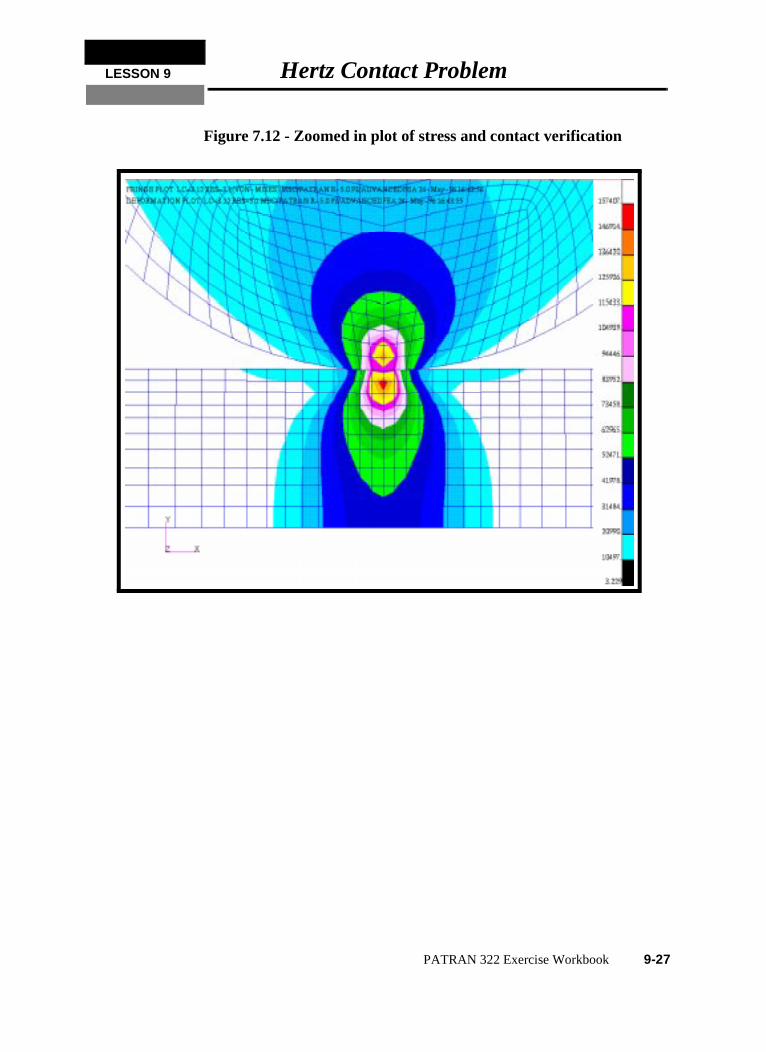
26. Make a deformed plot with Von Mises stresses plotted.
Before we make the deformed plot, we need to change the scalefactor of the result to 1.0 so that the plot will represent the actualdeformation In the Results form select the Deform Attributes icon..
Go back to the Selects Results form
Notice that the two bodies are in contact, and that there is even aslight deformation of both the plate and cylinder. To get a betterview, zoom in on the contact zone by using the View Corners icon.
Your model should now appear as shown in Figure 7.12:
Scale Factor: 1.0
◆ True Scale
❐ Show Undeformed Entities
Select Result Cases: select last load case
Select Fringe Result: Stress, Components
Result Type: Von Mises
Select Deformation Result: Deformation, Displacement
Apply
Reset Graphics
View Corners
9-26 PATRAN 322 Exercise Workbook
LESSON 9 Hertz Contact Problem
Figure 7.12 - Zoomed in plot of stress and contact verification
PATRAN 322 Exercise Workbook 9-27
,
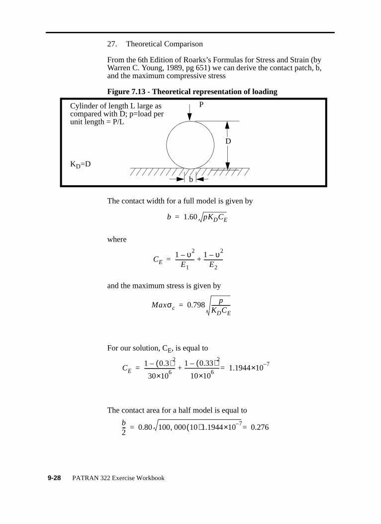
27. Theoretical Comparison
From the 6th Edition of Roarks’s Formulas for Stress and Strain (byWarren C. Young, 1989, pg 651) we can derive the contact patch, band the maximum compressive stress
Figure 7.13 - Theoretical representation of loading
The contact width for a full model is given by
where
and the maximum stress is given by
For our solution, CE, is equal to
The contact area for a half model is equal to
b
D
Cylinder of length L large ascompared with D; p=load perunit length = P/L
P
KD=D
b 1.60 pKDCE=
CE1 υ2
–E1
--------------1 υ2
–E2
--------------+=
Maxσc 0.798p
KDCE--------------=
CE1 0.3( )2
–
306×10
-----------------------1 0.33( )2
–
106×10
-------------------------- 1.19447–×10=+=
b2--- 0.80 100 000 10( )1.1944
7–×10, 0.276==
9-28 PATRAN 322 Exercise Workbook
LESSON 9 Hertz Contact Problem
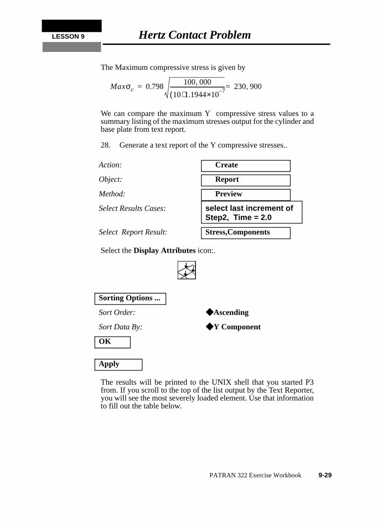
The Maximum compressive stress is given by
We can compare the maximum Y compressive stress values to asummary listing of the maximum stresses output for the cylinder andbase plate from text report.
28. Generate a text report of the Y compressive stresses..
Select the Display Attributes icon:.
The results will be printed to the UNIX shell that you started P3from. If you scroll to the top of the list output by the Text Reporter,you will see the most severely loaded element. Use that informationto fill out the table below.
Action: Create
Object: Report
Method: Preview
Select Results Cases: select last increment of Step2, Time = 2.0
Select Report Result: Stress,Components
Sorting Options ...
Sort Order: ◆ Ascending
Sort Data By: ◆ Y Component
OK
Apply
Maxσc 0.798100 000,
10( )1.19447–×10
------------------------------------------ 230 900,==
PATRAN 322 Exercise Workbook 9-29

Close the database and quit PATRAN.
This concludes this exercise.
Table 1: Maximum Compressive Stress
Theoretical AFEA % Diff
Max σc 230,900
9-30 PATRAN 322 Exercise Workbook