Embed Size (px)
Citation preview
REV 7-16-12
Herman Miller A02 Style
< cub i c Ie s • com ------- ------------- -- --------------------- ------------- ---------- --- -openpla n -.41
<cubiCles,com I Introduction I
-------------------------------------------------------------------- openplan III
These instruction sheets provide the necessary information for the safe installation of Action Office Series 2 System interiors for : • The installation crew, with pictorial and written
assembly instructions. • The specifier, in determining structural limitations
of components individually and collectively. • The user, to insure continued safe use of the product when maintaining and rearranging the product.
The characteristics of the Action Office Series 2 System require panel arrangements and panel supports as specified in this manual to insure safety. Rearrangement and additions to an installation must conform to the instructions provided to insure continued safe use of the product. OPS shall assume no responsibility for products that are altered in any way.
WARNING: Failure to follow instructions can result in product damage, personal injury, or both .
The information presented represents results and performance obtainable by filed laboratory staff under controlled usage conditions and the information may not be correct under those conditions.
The Action Office Series 2 System is composed of panels, hanging and free standing components, and accessories that may be precisely tailored to support organizational and individual needs. The Action Office Series 2 System is considered to be portable furniture and is therefore subject to applicable local fire, electrical , and building codes : therefore, check with local authorities before installation.
Warranty: OPS warrants its products to be free from defects in material and workmanship for a period of five years from the date of initial delivery. This warranty is made by the company only to purchasers acquiring the product directly from the company, its authorized dealers, or others who are specifically authorized by the company to sell such products. The company's obligation and the purchaser's remedy pursuant to this warranty are limited to repair or replacement of the defective part, labor not included, at the company's option , for the company's plant, of products which prove under normal use to be defective within the period stated, which remedy is expressly agreed to be exclusive as a condition of sale. No person, firm, or corporation is authorized to assume for the company any other liability in connection with the sale of the company's products.
IMPORTANT: SAVE THESE INSTRUCTIONS FOR LAYOUT CHANGES.
888-442-8242
Because of natural variations over which the company has no control, this warranty does not extend to color, grain, or texture of wood, marble, or leather, and the company does not warrant matching of color, grain, or texture.
The company also warrants any installation of its products performed by the company through employees hired and paid directly by the company to be free from defects in workmanship for a period of one year from the date the installation is completed . The company's obligation and the purchaser's remedy pursuant to this warranty are limited to repair of the installation work which may prove to be defective under normal use within the period stated, which remedy is expressly agreed to be exclusive as a condition of sale.
No person, firm , or corporation is authorized to assume for the company any liability in connection with the sale or installation of the company product except as above stated.
There are no other warranties except as expressly set forth above, either express or implied, including any warranty of merchantability or fitness for any particular purpose.
The company's liability with respect to its products or installation services shall not exceed that expressly set forth above irrespective of the theory upon which any claim might be based, including breach of contract, warrant, negligence, or strict liability of tort , and under no circumstances shall the company be liable for incidental or consequential damages.
Tools: Many products are factory-assembled and require installation only. Other products are shipped as subassemblies and are assembled during the installation process.
The following tools are necessary for field assembly and installation:
• 9/64" Allen Wrench • 1/4" Allen Wrench • No. 2 Phillips Head Screwdriver • No. 3 Phillips Head Screwdriver • Measuring Tape • Rubber Mallet • Slotted Screwdriver
The following tools will speed up large installations: • Hammer • Carpenter's Level • Electric Drill & Set of Drill Bits • Electric Screwdriver • Phillips Head Screw Bits, Nos. 1,2,3 • Chalk Line • 1/4" Hex Ratchet Allen Wrench • Pliers
·1 Panel Installation 1
.: cub i c I e s • co m -------- ------------- ---------- ------------- -- ------- --- ---------- --- openpla n .41
These panel installation instructions are written for the safety of the user. Follow them at specification time, initial installation time and recheck and follow them after each rearrangement.
Definition and Criteria A. A panel run is defined as two or more panels connected in a straight line. The beginning and ending panels are the first and last panels in the straight line. B. Panels mounted at right angles to panel runs are called support panels. Height of supporting panels to be equal to height of panels in panel run or 67" minimum height for 85" high panel or 53" minimum height for 67" high panels in panel run or 47" high minimum height for 53" high panels in panel run . C. All support panels must be at right angles to panels and on one or both sides depending on the panel loading spaced no greater than ten feet. See below for explanation and figures on non-loaded and loaded panels.
WARNING: Action Office Series 2 System open frame panels must not be used as support panels. Incorrect installation can cause product to fail and cause personal injury.
D. Non-loaded panel runs with support panels on one side of the panel run must have 36" minimum width support panels at the beginning and ending panels and at panel connecting joints. Spacing of support panels must be at intervals no greater than ten feet for fabric panels and eight feet for acoustical , glazed, and pass-thru panels. See figure 1. E. Support required for load bearing panels, beginning and ending panels, and at panel connecting joints spaced at intervals no greater than ten feet for fabric panels and eight feet for acoustical , glazed and pass-thru panels.
1. Panels loaded on side with shelves and/or lateral files and/ or work surfaces must have 36" minimum width supporting panels on loaded side of panels and spaced at intervals not greater than ten feet for fabric panels and eight feet for acoustical , glazed, and pass thru panels. See figure 3. 2. Panels loaded on both sides with shelves must have 12" minimum width , support panels for standard shelves and 18" minimum width support panels for EDP shelves on both sides of panel and spaced at intervals no greater than ten feet for fabric panels and eight feet for acoustical , glazed, and pass-thru panels . See figure 4. 3. Panels loaded on both sides with lateral files and/or work surfaces must have 24" minimum width support panels on both sides of panels and spaced at intervals no greater than ten feet for fabric panels and eight feet for acoustical , glazed, and pass thru panels . See figure 4.
IMPORTANT: SAVE THESE INSTRUCTIONS FOR LAYOUT CHANGES.
888-442-8242
F. Panel runs with 30" or 36" deep work surfaces require minimum support panels extending 30" for 30" deep work surfaces and 36" for 26" deep work surfaces and at intervals no greater than ten feet for fabric panels and eight feet for acoustical , glazed, and pass thru panels . See figures 3 and 4. G. "T" and "X" connectors are used to connect panel runs to either a structural wall or building column. See figure 5.
Definition of a structural wall: OPS definition of a structural wall is a load bearing wall constructed of materials such as poured concrete or concrete blocks or a composite board (drywall) attached to metal or wood studs.
The composite board (drywall) must be 1/8" thick or greater. • Wood studs must be a nominal 2" x 4" size. • Metal studs must be "e" channel 20 GA. Thick. • The metal or wood studs must be on centers no greater than
24" and have a maximum height of 4' restrained at the floor and at the ceiling .
Load Capacities: OPS will not under any circumstances guarantee or assume responsibility for loading performance beyond the basic individual component capacities given below.
Pencil Drawer: 5 Ibs. • Storage/File and Medium Drawers: 25 Ibs.
Two-Drawer Storage: 25 Ibs. Shelves: 150 Ibs. Lateral Files : 100 Ibs. Hanging Working Surfaces. Up to and including 60" in width :
• For 30" Depth : 200 Ibs • For 24" Depth : 200 Ibs.
• Hanging work surfaces over 60" up to and including 96" in width : • For 24" Depth (with three work surface supports or
two work surface supports and two work surface support clips or four work surface supports): 250 Ibs
For 30" Depth (with four work surface supports) : 250 Ibs
2
I Panel Installation I
.: cub i c I e s • co m ----------------- ------------- ---------- --- ------------ -------------- openpla n .41 WARNING: Failure to observe recommended practices such as loading beyond capacities can result in unsafe usage conditions and product damage or personal injury.
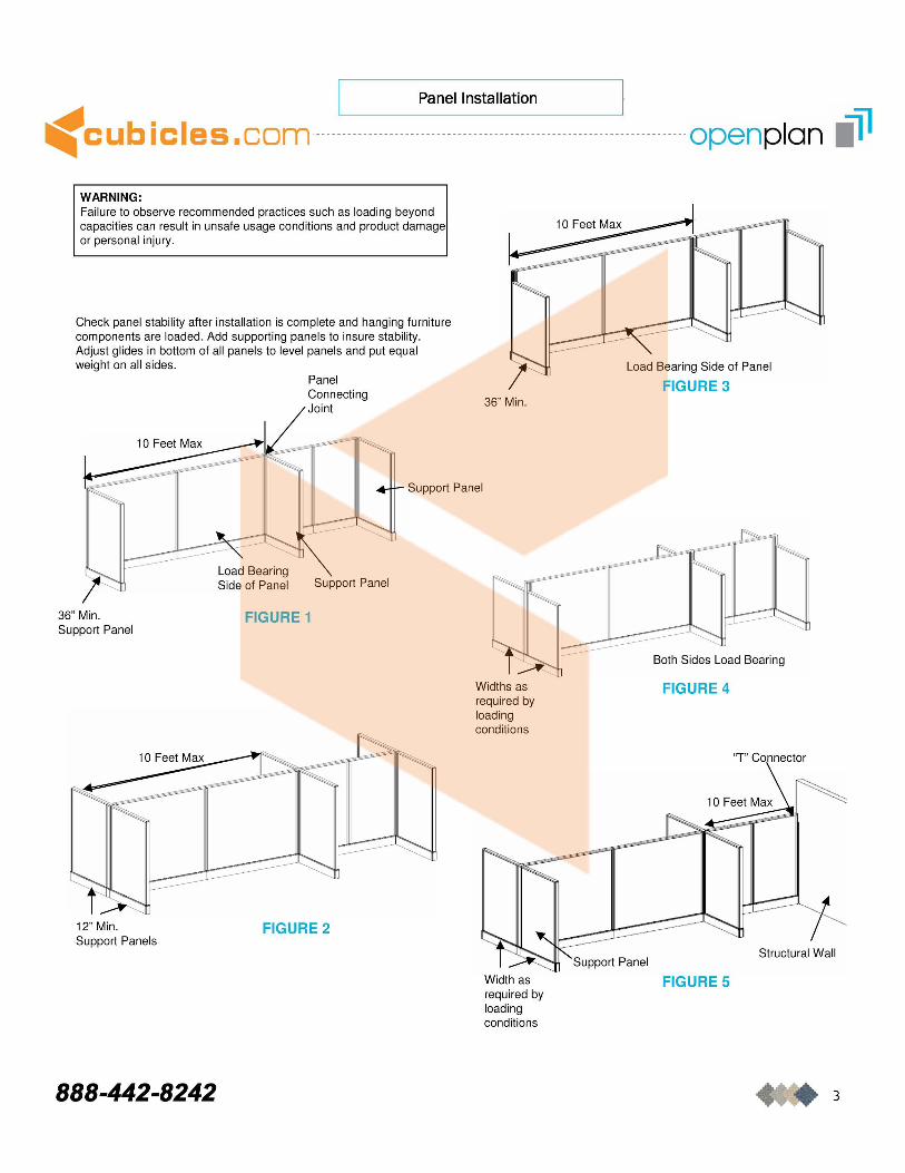
Check panel stability after installation is complete and hanging furniture components are loaded. Add supporting panels to insure stability. Adjust glides in bottom of all panels to level panels and put equal weight on all sides.
Panel Connecting Joint 36" Min.
Support Panel
36" Min. Support Panel
12" Min. Support Panels
888-442-8242
Support Panel
FIGURE 1
FIGURE 2
Widths as required by loading conditions
Width as required by loading conditions
FIGURE 3
Both Sides Load Bearing
FIGURE 4
"T" Connector
Structural Wall
FIGURE 5
3
Panel-to-Panel Connection with Panel Connector
.: cub i c I e s • com ------------- -------------------------------------------------------- openpla n .41
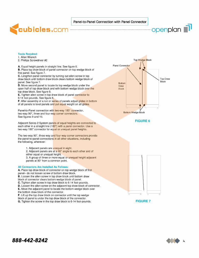
Tools Required : 1. Allen Wrench 2. Phillips Screwdriver #2
A. Equal height panels in straight line. See figure 6. B. Place top draw block of panel connector on top wedge block of first panel. See figure 7. C. Lengthen panel connector by turning out allen screw in top draw block until bottom draw block clears bottom wedge block of panel. See figure 7. D. Move second panel to locate its top wedge block under the open half of top draw block and with bottom wedge block over the top draw block. See figure 8. E. Tighten allen screw in top draw block of panel connector to 6-14 foot pounds. See figure 8. F. After assembly of a run or series of panels adjust glides in bottom of all panels to level panels and put equal weight on all glides.
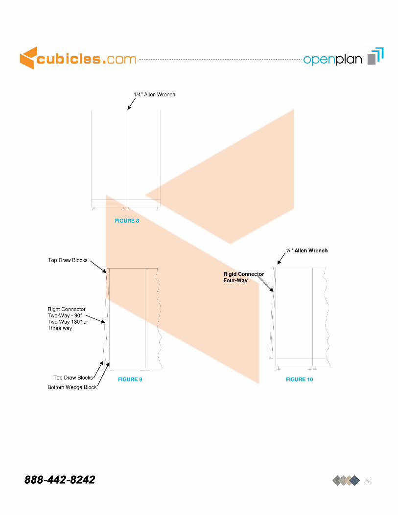
Panel-to-Panel connection with two-way 180° connector, two-way 90°, three and four-way corner connectors . See figures 9 and 10.
Adjacent Series 2 System panels of equal heights are connected to each other in a straight line (1 80°) with a panel connector. Use a two-way 180° connector for equal or unequal panel heights.
The two-way 90°, three-way and four-way corner connectors provide the panel-to-panel connections in all other situations, including the following , wherever:
1. Adjacent panels are unequal in eight. 2. Adjacent panels are at a 90° angle to each other and of either equal or unequal height. 3. A group of three or more equal or unequal height adjacent panels at 90° from a common point.
All Connectors Are Installed As Follows: A. Place top draw block of connector on top wedge block of first panel-- do not loosen screw of bottom draw block. B. Loosen the allen screw in top draw block until bottom draw block of connector clears bottom wedge block of panel. C. Tighten allen screw in top draw block to 6-14 foot-pounds . D. Loosen the allen screw on the adjacent top draw block of connector. E. Move the adjacent panel to locate the bottom wedge block over the bottom draw block of the connector. F. Lift up the top draw block on connector until the top wedge block of panel is under the top draw block of the connector. G. Tighten the screw in the top draw block to 6-14 foot-pounds.
888-442-8242
Top Wedge Block
p,,,, CO""~to, t \ ""0m ~ Draw I Block
Bottom Wedge Block
FIGURE 6
FIGURE 7
Top Draw Block
4
.: cub i c I e s • com -------- ------------- ------------ ---------------------------------- openpla n -.41
±J FIGURE 8
Top Draw Blocks ~~ ___ ~~
Right Connector Two-Way - 90 0
Two-Way 1800 or Three way
Top Dco. BIOCk'~IGURE 9
Bottom Wedge Block
888-442-8242
Rigid Connector Four-Way
I %" Allen Wrench
FIGURE 10
5
Electrical Distribution & Wire Management
<cubiCles,com -----------------------------------------------------------------------openplan III
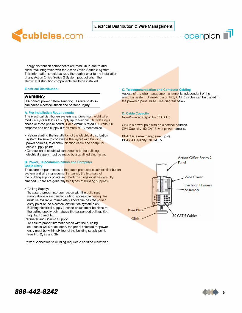
Energy distribution components are modular in nature and allow total integration with the Action Office Series 2 System . This information should be read thoroughly prior to the installation of any Action Office Series 2 System product when the electrical distribution components are to be installed.
Electrical Distribution:
WARNING: Disconnect power before servicing . Failure to do so can cause electrical shock and personal injury.
A. Pre-Installation Requirements The electrical distribution system is a four-circu it, eight wire modular system that can supply up to four circuits with single phase or three phase power. Each circuit is rated 125 volts, 20 amperes and can supply a maximum of 13 receptacles.
• Before starting the installation of the electrical distribution system, be sure to coordinate the layout with building power sources, telecommunication cable and computer cable supply points .
• Connection of electrical components to the building electrical supply must be made by a qualified electrician.
B. Power, Telecommunication and Computer Cable Entry To assure proper access to the panel product's electrical distribution system and wire management channel , the interface of the building supply points and the furnishings must be carefully planned. There are generally two types of building supplies :
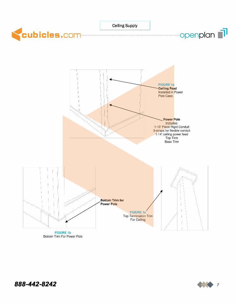
• Ceiling Supply : To assure proper interconnection with the building's wiring above a suspended ceiling , accessible ceiling tiles must be available immediately above the desired power entry point of the electrical distribution system plan. Building electrical supply junction boxes must be close to the ceiling supply point above the suspended ceiling . See Fig . 1 a, 1 band 1 c.
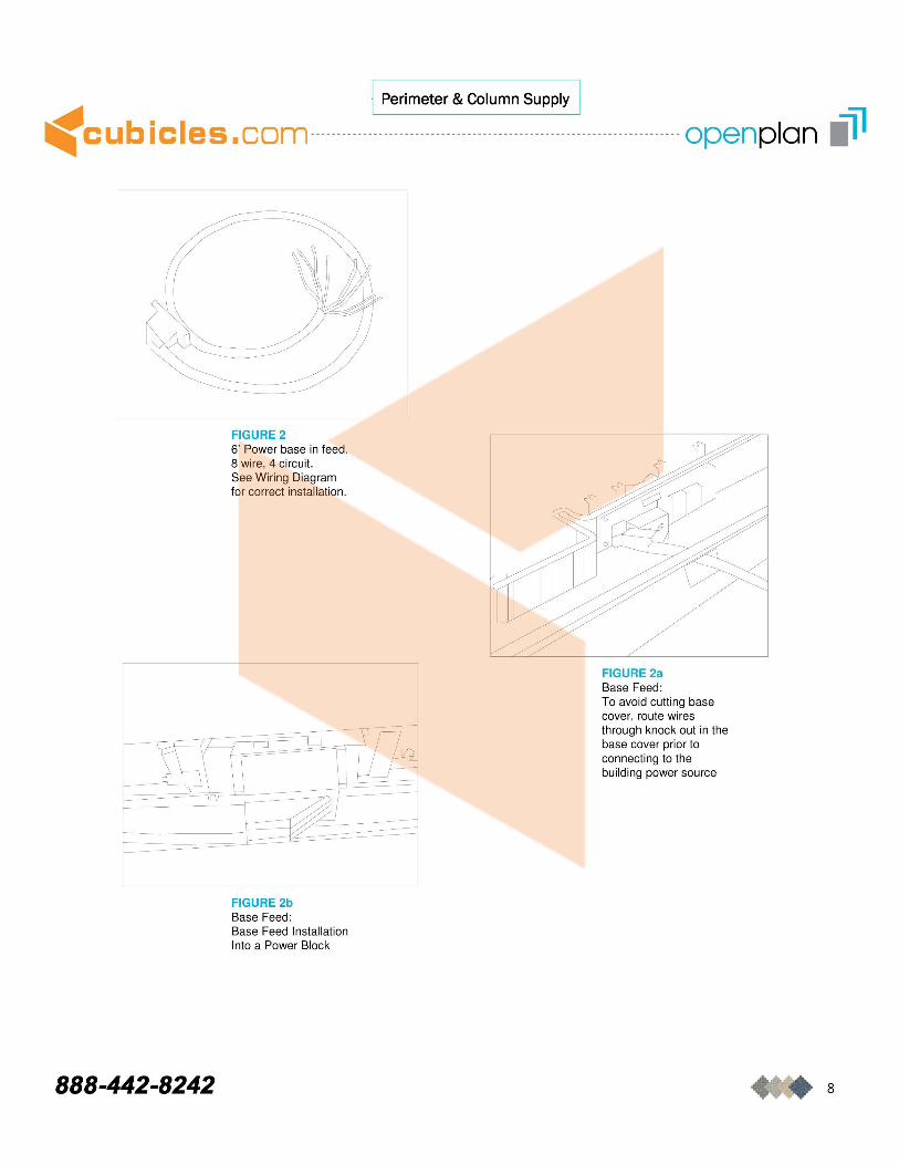
Perimeter and Column Supply: To assure proper interconnection with the building sources in walls or columns, the panel selected for power entry must be within six feet of the building supply point. See Fig . 2, 2a and 2b.
Power Connection to building requires a certified electrician.
888-442-8242
C. Telecommunication and Computer Cabling Access of the wire management channel is independent of the electrical system. A maximum of thirty CAT 5 cables can be placed in the powered panel base _ See diagram below.
D. Cable Capacity Non-Powered Capacity- 60 CAT 5.
CF4 is a power pole with an electrical harness. CF4 Capacity- 60 CAT 5 with power harness.
PP4x4 is a wire management pole . PP4 x 4 Capacity- 70 CAT 5.
Base Plate
Gl ide~
Action Office Series 2
ide Cover
Electrical Harness Assembly
30 CAT 5 Cables
6
I Ceiling Supply I
.: cub i c I e s • co m ------------------------------------ -------------------- ------------- openpla n .41
L FIGURE 1b
Bottom Trim For Power Pole
888-442-8242
] FIGURE 1a Ceiling Feed Installed in Power Pole Case.
Power Pole Includes:
1-10' Piece Rigid Conduit 3-straps for flexible conduit
1-14' ceiling power feed Top Trim Base Trim
Power Pole ~ Bottom Trim for
FIGURE 1c Top Termination Trim
For Ceil ing
7
I Perimeter & Column Supply I
.: cub i c I e s • com -------------------------------- ------------ ------------ ------------ openpla n .• 41
888-442-8242
FIGURE 2 6' Power base in feed. 8 wire, 4 circuit. See Wiring Diagram for correct installation .
FIGURE 2b Base Feed : Base Feed Installation Into a Power Block
FIGURE 2a Base Feed : To avoid cutting base cover, route wires through knock out in the base cover prior to connecting to the building power source
8
I Wiring Diagram I
.: cub i c I e s • com ----- ------------ ------------ ------------ --------------------------- openpla n .41
COI+IECTlON 'TO A GRO!J.I~ TrlREE.Ptw;E s"tSlBA
~--..-- ~ a!"le Elfi!:
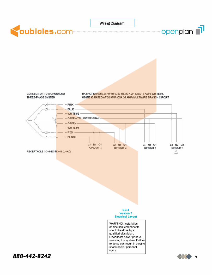
ftti.TlNG: 1200'211&.1. 3-ptnWE, €{I Ht. 2& fOSA 1'5 AMP} lYE tttI . WI-ITE. t2 RAl'EDAT 20 lIMP (CS .... 26AMP)TlWlRE BRANCH CIRClIlT
~ WHII
- G EE
~~EE
- WHIT
W'fnLOW OR GRAV
H
Ef1
~ ........... :..-- - RED
888-442-8242
I L 1 ttl 01
OIRCI.IT I l2, N 0 1
CfROUIT l
2-3-4 Version 2
Electrical Layout
WARNING : Installation
U. til l 0 1 CIRCI.IT3
of electrical components should be done by a qualified electrician . Disconnect power prior to servicing the system. Failure to do so can result in electric shock and/or personal injury.
U N2 Q2 ~~IH
6.
9
·1 Electrical Distribution System 1
.: cub i c I e s • co m -------- ------------- ------------------------- -------------------- --- openpla n .41 Connection & Receptacle Installation
&. WARNING Disconnect power before servicing. Failure to do so can cause electrical shock and personal injury.
NOTE: BEFORE INTERCONNECTING THE ELECTRICAL COMPONENTS, ALL PANELS MUST BE INSTALLED ACCORDING TO THE ACTION OFFICE SERIES 2 SYSTEM FLOOR PLAN.
NOTE: FOR EASE OF INSTALLATION, START AT POWER ENTRY PANELS AND PROCEED MAKING CONNECTIONS THROUGH THE SYSTEM.
NOTE: ELECTRICALLY INTERCONNECTED PANELS MUST BE MECHANICALLY INTERCONNECTED.
CONNECTION OF ACTION OFFICE SERIES 2 SYSTEM PANELS:
SEE FIGURES 1 THRU 8 FOR DESCRIPTION OF COMPONENTS AND DETAILS OF INSTALLATION.
USE THE FLEXIBLE CONNECTORS SUPPLIED WITH EACH PANEL TO CONNECT THE ELECTRICAL DISTRIBUTION ASSEMBLY IN THE PANEL BASE. THE FLEXIBLE CONNECTOR MAY BE USED TO MAKE CONNECTIONS ACROSS TWO-WAY, THREE-WAY OR FOUR-WAY PANELJUNCTIONS. SEE FIGURES 17 THROUGH 19 FOR EXAMPLES OF INSTALLATIONS.
& WARNING All electrical connections must be fully engaged and locked. Loose connections can cause fire and/or electrical shock.
PANEL TO PANEL CONNECTION:
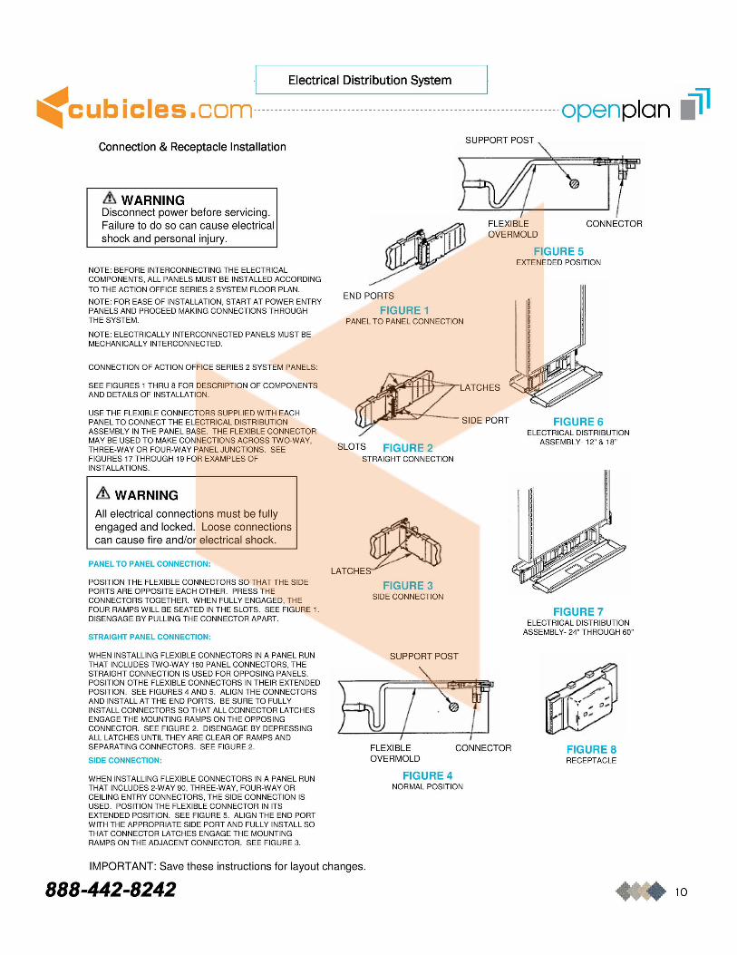
POSITION THE FLEXIBLE CONNECTORS SO THAT THE SIDE PORTS ARE OPPOSITE EACH OTHER. PRESS THE CONNECTORS TOGETHER. WHEN FULLY ENGAGED, THE FOUR RAMPS WILL BE SEATED IN THE SLOTS. SEE FIGURE 1. DISENGAGE BY PULLING THE CONNECTOR APART.
STRAIGHT PANEL CONNECTION:
WHEN INSTALLING FLEXIBLE CONNECTORS IN A PANEL RUN THAT INCLUDES TWO-WAY 180 PANEL CONNECTORS, THE STRAIGHT CONNECTION IS USED FOR OPPOSING PANELS. POSITION OTHE FLEXIBLE CONNECTORS IN THEIR EXTENDED POSITION. SEE FIGURES 4 AND 5. ALIGN THE CONNECTORS AND INSTALL AT THE END PORTS. BE SURE TO FULLY INSTALL CONNECTORS SO THAT ALL CONNECTOR LATCHES ENGAGE THE MOUNTING RAMPS ON THE OPPOSING CONNECTOR. SEE FIGURE 2. DISENGAGE BY DEPRESSING ALL LATCHES UNTIL THEY ARE CLEAR OF RAMPS AND SEPARATING CONNECTORS. SEE FIGURE 2.
SIDE CONNECTION:
WHEN INSTALLING FLEXIBLE CONNECTORS IN A PANEL RUN THAT INCLUDES 2-WAY 90, THREE-WAY, FOUR-WAY OR CEILING ENTRY CONNECTORS, THE SIDE CONNECTION IS USED. POSITION THE FLEXIBLE CONNECTOR IN ITS EXTENDED POSITION. SEE FIGURE 5. ALIGN THE END PORT WITH THE APPROPRIATE SIDE PORT AND FULLY INSTALL SO THAT CONNECTOR LATCHES ENGAGE THE MOUNTING RAMPS ON THE ADJACENT CONNECTOR. SEE FIGURE 3.
END PORTS
FIGURE 1 PANEL TO PANEL CONNECTION
SUPPORT POST
I FLEXIBLE OVERMOLD
CONNECTOR
FIGURE 5 EXTENEDED POSITION
SIDE PORT FIGURE 6 ELECTRICAL DISTRIBUTION
ASSEMBLY-12" & 18" SLOTS FIGURE 2
STRAIGHT CONNECTION
LATCHE~ FIGURE 3
SIDE CONNECTION
SUPPORT POST
bij7~
FIGURE 7 ELECTRICAL DISTRIBUTION
ASSEMBLY- 24" THROUGH 60"
FLEXIBLE CONNECTOR FIGURE 8 OVERMOLD RECEPTACLE
FIGURE 4 NORMAL POSITION
IMPORTANT: Save these instructions for layout changes.
888-442-8242 10
·1 Receptacle Installation & Removal 1
.: cub i c I e s • co m --------------------------------- ----------------------------- -------- openpla n .41 &' WARNING Disconnect power before servicing. Failure to do so can cause electrical shock and personal injury.
&. WARNING All electrical connections must be fully engaged and locked. Loose connections can cause fire and/or electrical shock.
NOTE: RECEPTACLES CAN BE INSTALLED ON BOTH SIDES OF THE PANELS. TWO RECEPTACLES PER SIDE CAN BE INSTALLED ON 24" THRU 60" PANELS. NO RECEPTACLES CAN BE INSTALLED ON 12" AND 18" PANELS.
NOTE: IN A PROMINENT LOCATION, NOT MORE THAN 12 OUTLETS SHALL BE SUPPLIED BY ONE CIRCUIT.
BRACKET HOOKS
INSTALLATION:
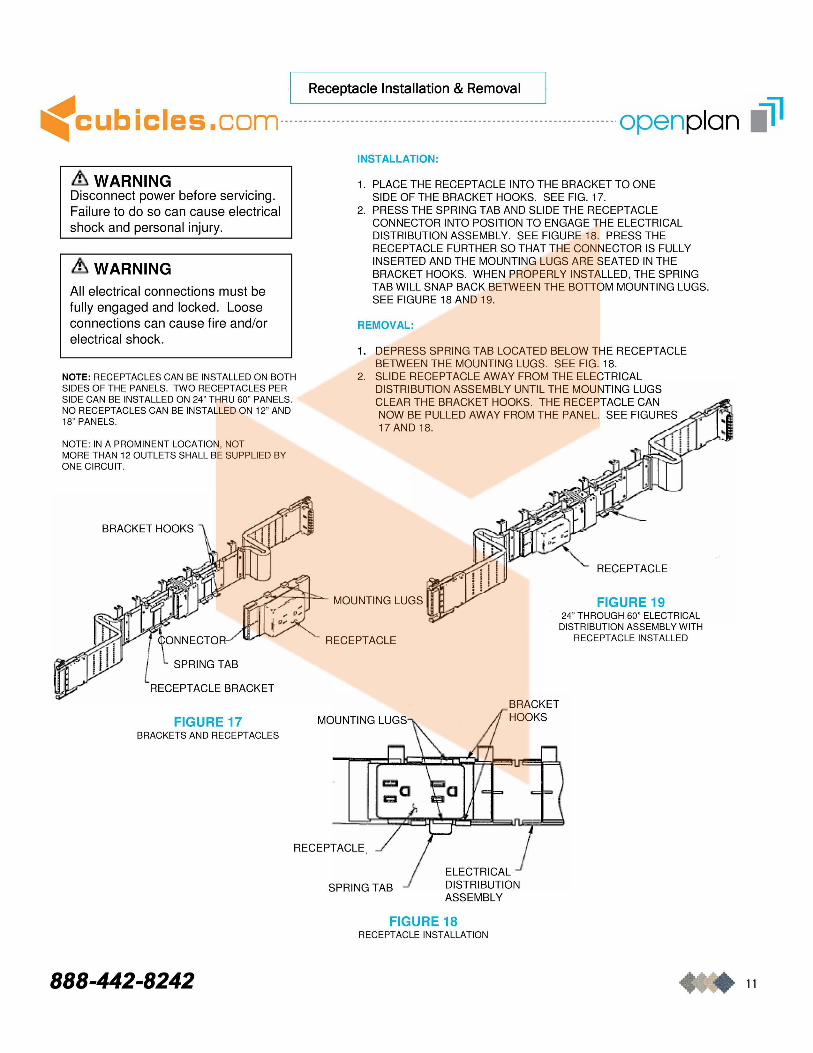
1. PLACE THE RECEPTACLE INTO THE BRACKET TO ONE SIDE OF THE BRACKET HOOKS. SEE FIG. 17.
2. PRESS THE SPRING TAB AND SLIDE THE RECEPTACLE CONNECTOR INTO POSITION TO ENGAGE THE ELECTRICAL DISTRIBUTION ASSEMBLY. SEE FIGURE 18. PRESS THE RECEPTACLE FURTHER SO THAT THE CONNECTOR IS FULLY INSERTED AND THE MOUNTING LUGS ARE SEATED IN THE BRACKET HOOKS. WHEN PROPERLY INSTALLED, THE SPRING TAB WILL SNAP BACK BETWEEN THE BonOM MOUNTING LUGS. SEE FIGURE 18 AND 19.
REMOVAL:
1.
2.
RECEPTACLE
~"",""""'-:H=~ MOUNTING LUGS FIGURE 19
SPRING TAB
RECEPTACLE BRACKET
FIGURE 17 BRACKETS AND RECEPTACLES
888-442-8242
RECEPTACLE
RECEPTACLE,
SPRING TAB
24" THROUGH 60" ELECTRICAL DISTRIBUTION ASSEMBLY WITH
RECEPTACLE INSTALLED
BRACKET HOOKS
ELECTRICAL J DISTRIBUTION ASSEMBLY
FIGURE 18 RECEPTACLE INSTALLATION
11
Cable Management Component Installation
.: cub i c I e s • com ----------------------------------------------------------------------- openpla n .41
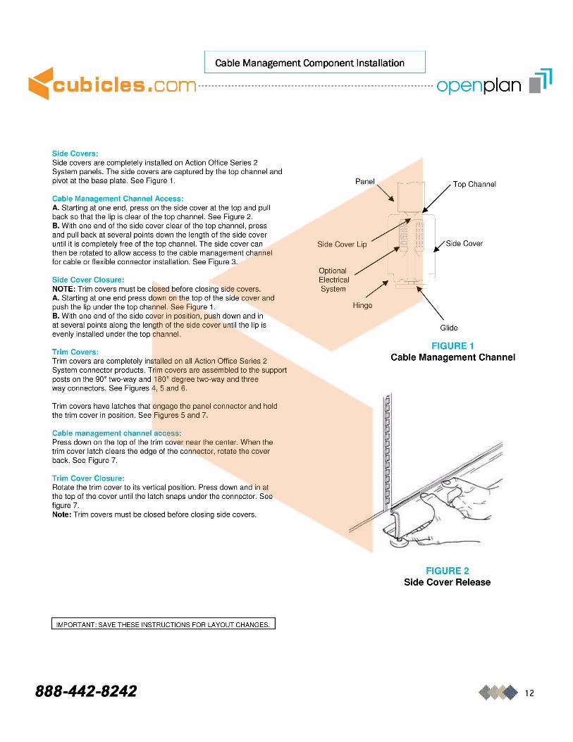
Side Covers: Side covers are completely installed on Action Office Series 2 System panels . The side covers are captured by the top channel and pivot at the base plate. See Figure 1.
Cable Management Channel Access: A. Starting at one end, press on the side cover at the top and pull back so that the lip is clear of the top channel. See Figure 2. B. With one end of the side cover clear of the top channel , press and pull back at several points down the length of the side cover until it is completely free of the top channel. The side cover can then be rotated to allow access to the cable management channel for cable or flexible connector installation. See Figure 3.
Side Cover Closure: NOTE: Trim covers must be closed before closing side covers . A. Starting at one end press down on the top of the side cover and push the lip under the top channel. See Figure 1. B. With one end of the side cover in position , push down and in at several points along the length of the side cover until the lip is evenly installed under the top channel.
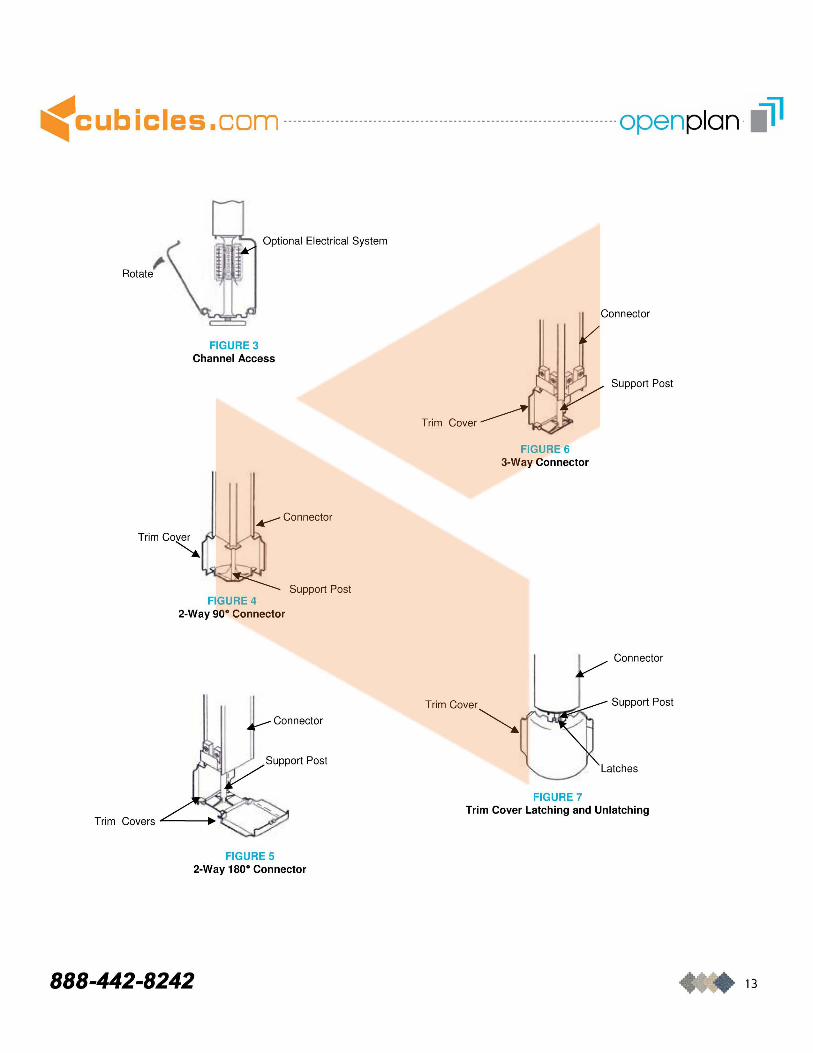
Trim Covers: Trim covers are completely installed on all Action Office Series 2 System connector products. Trim covers are assembled to the support posts on the 90 0 two-way and 1800 degree two-way and three way connectors . See Figures 4, 5 and 6.
Trim covers have latches that engage the panel connector and hold the trim cover in position . See Figures 5 and 7.
Cable management channel access: Press down on the top of the trim cover near the center. When the trim cover latch clears the edge of the connector, rotate the cover back. See Figure 7.
Trim Cover Closure: Rotate the trim cover to its vertical position . Press down and in at the top of the cover until the latch snaps under the connector. See figure 7. Note: Trim covers must be closed before closing side covers .
I IMPORTANT: SAVE THESE INSTRUCTIONS FOR LAYOUT CHANGES.
888-442-8242
panel~ I Top Channel
Atf( Side Cover Lip /~~] /Slde Cover
Optional / h~ Electncal
System / r \
Hinge
Glide
FIGURE 1 Cable Management Channel
FIGURE 2 Side Cover Release
12
.: cub i c I e s • com ------- ------------- ------------- ------------------------- ----------- openpla n -.41
Rotate , Optional Electrical System .... " .... ........ '
FIGURE 3 Channel Access
..- Connector
Trim Cover
'-:..
Support Post FIGURE 4
2-Way 90' Connector
Trim Covers .L-__ •
FIGURE 5 2-Way 180' Connector
888-442-8242
Trim Cover
FIGURE 6 3-Way Connector
Trimcover~ A::::--r_~
FIGURE 7
Connector
Support Post
Connector
Support Post
Trim Cover Latching and Unlatching
13
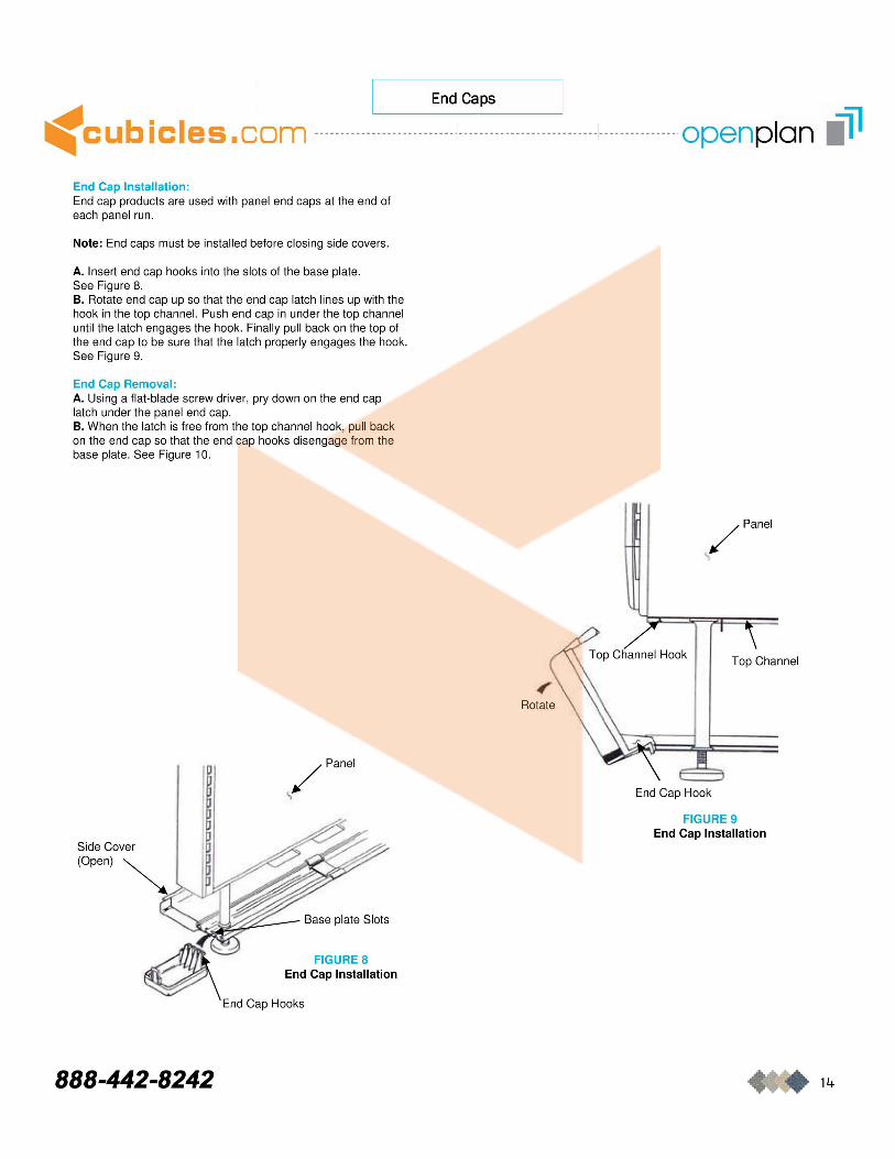
I End Caps I -< cub i c I e s • com ---------------- --- ---------------------- ------------- -------------- -openpla n .41 End Cap Installation: End cap products are used with panel end caps at the end of each panel run .
Note: End caps must be installed before closing side covers .
A. Insert end cap hooks into the slots of the base plate. See Figure 8. B. Rotate end cap up so that the end cap latch lines up with the hook in the top channel. Push end cap in under the top channel until the latch engages the hook. Finally pull back on the top of the end cap to be sure that the latch properly engages the hook. See Figure 9.
End Cap Removal: A. Using a flat-blade screw driver, pry down on the end cap latch under the panel end cap. B. When the latch is free from the top channel hook, pull back on the end cap so that the end cap hooks disengage from the base plate . See Figure 10.
Side Cover
(Open) ~
888-442-8242
/panel
..
Base plate Slots
FIGURE 8
/panel
Top Channel
End Cap Hook
FIGURE 9 End Cap Installation
14