Embed Size (px)
Citation preview
Valid: 12.2008 / 50077476 E
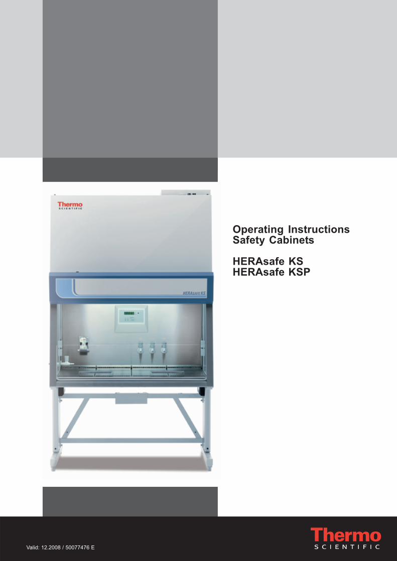
Operating InstructionsSafety Cabinets
HERAsafe KSHERAsafe KSP

Operating Instructions Safety Cabinet HERAsafe KS / KSP
2
© 2008 Thermo Fisher Scientific Inc. All rights reserved.These operating instructions are protected by copyright. Rights resulting the-reof, particularly reprint, photomechanical or digital postprocessing or reproduction,even in part, are only allowed with the written consent of Thermo Electron LED GmbH.This regulation does not apply to reproductions for in-plant use.
TrademarksAll trademarks mentioned in the operating instructions are the exclusive propertyof the respective manufacturers.
Thermo Electron LED GmbHRobert-Bosch-Straße 1D - 63505 LangenselboldGermany

Operating Instructions Safety Cabinet HERAsafe KS / KSP
3
Contents
1. General notes ......................................................................................... 61.1 General safety instructions ............................................................. 61.2 Warranty ......................................................................................... 71.3 Explanation of symbols................................................................... 7
1.3.1 Symbols used in the operating instructions ............................. 71.3.2 Symbols on the device ............................................................. 8
1.4 Use of the device ............................................................................ 81.4.1 Correct use ............................................................................... 81.4.2 Incorrect use: ............................................................................ 9
1.5 Standards and safety regulations ................................................... 9
2. Delivery ................................................................................................. 102.1 Standard components ................................................................... 102.2 Acceptance inspection .................................................................. 102.3 Transport lock and device packaging ........................................... 10
3. Installation ............................................................................................ 113.1 Ambient conditions ....................................................................... 113.2 Room ventilation ........................................................................... 113.3 Correct location............................................................................. 123.4 Installation in line .......................................................................... 123.5 Transport ....................................................................................... 13
4. Unit description .................................................................................... 144.1 Overall view .................................................................................. 144.2 Safety system ............................................................................... 174.3 Filter system ................................................................................. 184.4 Controls and display ..................................................................... 204.5 Sample chamber access .............................................................. 214.6 Device interfaces .......................................................................... 224.7 Sample chamber illumination ....................................................... 234.8 UV lamp unit ................................................................................. 244.9 Working area................................................................................. 24
5. Start-up .................................................................................................. 255.1 Initial operation ............................................................................. 255.2 Installing unit and accessories ..................................................... 255.3 Levelling the cabinet ..................................................................... 275.4 Activating the remote control ........................................................ 285.5 Power supply connection ............................................................. 295.6 RS 232 interface connection ........................................................ 315.7 UV connection .............................................................................. 315.8 Installation test .............................................................................. 32
6. Handling and control ........................................................................... 336.1 Display .......................................................................................... 33
6.1.1 Functions of the display components ..................................... 336.1.2 Display during the calibration routine ..................................... 346.1.3 Display in OFF mode .............................................................. 346.1.4 Display in work mode ............................................................. 346.1.5 Power interruption .................................................................. 346.1.6 Display and functions after a power failure ............................ 346.1.7 Failure messages ................................................................... 34
6.2 Description of the operating modes ............................................. 356.3 Remote control ............................................................................. 37
6.3.1 Basic functions ....................................................................... 376.3.2 Moving the front window to the working position ................... 386.3.3 Silencing the audible alarm signal ......................................... 396.3.4 Switching the illumination on and off ...................................... 40
Operating Instructions Safety Cabinet HERAsafe KS / KSP
4
Contents
6.3.5 Activating and deactivating the internal power supply ........... 406.3.6 Displaying the UV disinfection time........................................ 406.3.7 Activating and deactivating the potential-free contact
(optional) ................................................................................. 416.3.8 Switching the cabinet to OFF mode ....................................... 416.3.9 Setting the time....................................................................... 416.3.10 Displaying the downflow velocity ........................................... 426.3.11 Displaying the operating hours of the HEPA filters ................ 436.3.12 Displaying the Performance Factor ........................................ 436.3.13 Setting and activating the timer .............................................. 446.3.14 Deactivating the timer ............................................................. 456.3.15 Setting the UV disinfection time ............................................. 466.3.16 Starting the UV disinfection .................................................... 466.3.17 Cancelling the UV disinfection ............................................... 476.3.18 Activating the stop watch ....................................................... 47
6.4 Pilot switch .................................................................................... 486.4.1 Moving the front window: ....................................................... 486.4.2 Silencing the audible alarm signal: ........................................ 496.4.3 Switching the device to OFF mode ........................................ 49
7. Operation .............................................................................................. 507.1 Hygiene preparations for the sample chamber ............................ 507.2 Preparing the sample chamber .................................................... 507.3 Response to failure messages ..................................................... 507.4 Work rules ..................................................................................... 51
8. Shut-down............................................................................................. 528.1 Interrupting an operation .............................................................. 528.2 Shutting the unit down .................................................................. 52
9. Cleaning and decontamination .......................................................... 539.1 Decontamination procedure ......................................................... 539.2 Wipe/spray disinfection................................................................. 539.3 UV disinfection after a wipe/spray disinfection ............................ 54
9.3.1 UV disinfection using the integral UV lamps .......................... 549.3.2 UV disinfection using a mobile UV device ............................. 55
9.4 Sterilization with formaldehyde ..................................................... 559.5 Cleaning the exterior surfaces...................................................... 559.6 Cleaning the floorpan ................................................................... 56
10. Maintenance ......................................................................................... 5710.1 Inspection...................................................................................... 5710.2 Service .......................................................................................... 57
10.2.1 UV lamps ................................................................................ 5710.2.2 Sample chamber illumination ................................................. 5810.2.3 Replacing the front window seal ............................................ 58
10.3 Retrofitting and repairs ................................................................ 59
11. Disposal ................................................................................................ 6011.1 Disposal procedure ...................................................................... 60
12. Technical data ...................................................................................... 62
13. Device log ............................................................................................. 69
14. Certificate of decontamination ........................................................... 70

Operating Instructions Safety Cabinet HERAsafe KS / KSP
5
Figures
Fig. 1 Device locations in a room ...........................................................12Fig. 2 Lift points ......................................................................................13Fig. 3-a Overall view / model Herasafe KS ...............................................15Fig. 3-b Overall view / model Herasafe KSP.............................................16Fig. 4-a Filter system with downflow filter and exhaust
air filter / model Herasafe KS .......................................................18Fig. 4-b Filter system with primary filter, downflow filter and exhaust
air filter / model Herasafe KSP .....................................................19Fig. 5-a Controls and indicators ................................................................20Fig. 5-b Display with remote control sensor ..............................................20Fig. 6-a Access through front cover ..........................................................21Fig. 6-b Access through front window .......................................................21Fig. 7-a Supply interfaces ..........................................................................22Fig. 7-b Sample chamber illumination .......................................................23Fig. 8 UV lamp unit .................................................................................24Fig. 9 Working area on the workplate, armrests ....................................24Fig. 10-a Stand installation / model Herasafe KS .......................................25Fig. 10-b Stand installation / model Herasafe KSP .....................................26Fig. 10-c Drain valve installation .................................................................27Fig. 11 Inserting the batteries ...................................................................28Fig. 12 RS 232 interface connection ........................................................31Fig. 13 UV connection ..............................................................................31Fig. 14 Functions of the display components ..........................................33Fig. 15 Basic functions of the remote control ...........................................37Fig. 16 Basic functions of the pilot switch ................................................48Fig. 17 Sitting posture ..............................................................................52Fig. 18 Front window seal replacement ...................................................58

Operating Instructions Safety Cabinet HERAsafe KS / KSP
6
1. General notes
The following are the addresses of the international ThermoSales Organisations.
1.1 General safety instructions
These safety instructions describe the safety features of the Herasafe KS andHerasafe KSP series.The safety cabinet has been manufactured in keeping with the latesttechnological developments and has been tested before delivery for its correctfunction. It may, however, present potential hazards if it is not used accordingto the intended purpose or outside of operating parameters. Therefore, thefollowing procedures must always be observed:• The safety cabinet must be operated only by trained and authorized personnel.• For any operation of this unit, the operator must prepare clear and concise
written instructions in the language of the operating and cleaning personnelbased on these operating instructions, applicable safety data sheets, planthygiene guidelines, and technical regulations, in particular:• which decontamination measures are to be applied for the cabinet and
accessories,• which protective measures apply while specific agents are used,• which measures are to be taken in the case of an accident.
• Repairs to the device must be carried out only by trained and authorized expertpersonnel.
• The contents of the operating instructions are subject to change withoutfurther notice.
• Concerning translations into foreign languages, the German version of theseoperating instructions is binding lease.
• Keep these operating instructions close to the unit so that safety instructionsand important information are always accessible.
• Should you encounter problems that are not detailed adequately in theseoperating instructions, please contact Thermo Electron LED GmbHimmediately for your own safety.
Postal address GermanyThermo Electron LED GmbHRobert-Bosch-Straße 1D - 63505 Langenselbold
Enquiries from Germany:PhoneSales 0800 1 536376Service 0800 1 112110FaxSales/Service 0800 1 [email protected]
International enquiriesTel. + 49 (0) 6184 / 90-6940Fax + 49 (0) 6184 / [email protected]

Operating Instructions Safety Cabinet HERAsafe KS / KSP
7
1. General notes
1.2 Warranty
Thermo Electron LED GmbH warrant the operational safety and functions of thesafety cabinet only under the condition that:• the device is operated and serviced exclusively in accordance with its intended
purpose and as described in these operating instructions,• the device is not modified,• only original spare parts and accessories that have been approved by Thermo
Electron LED GmbH are used,• inspections and maintenance are performed at the specified intervals,• an installation test is performed prior to the initial operation of the device and
that a repeat test is performed on the occasion of all inspections and repairs.The warranty is valid from the date of delivery of the device to the operator.
1.3 Explanation of symbols
1.3.1 Symbols used in the operating instructions
WARNING!
is used if non-observance may cause seriousor even lethal injuries.
CAUTION!
is used if non-observance may cause mediumto minor injuries or damage.
NOTE
is used for hints and useful information.
RECYCLING!
Valuable raw materials can be reused.

Operating Instructions Safety Cabinet HERAsafe KS / KSP
8
1. General notes
1.3.2 Symbols on the device
Betriebsanleitung beachten (Decke Schaltraum)
Observe operating instructions (cover electrical box)
Cytostatic agents (left device front)
Checked safety (Cover light dome)
T5A note (sample chamber fusing)
RS 232 interface (connection label)
Armrest installation(right side of light dome)
1.4 Use of the device
1.4.1 Correct use
Model Herasafe KS:The safety cabinet is a laboratory device for installation and operation inmicrobiological and biotechnical laboratories of safety levels 1, 2, and 3. It hasbeen designed as a Class II microbiological safety cabinet, in accordance withEN 12469 / 2000.Depending on the hazard level of the agents involved, the operator mustprepare in writing appropriate decontamination procedures for the device andthe accessories used in the sample chamber.

Operating Instructions Safety Cabinet HERAsafe KS / KSP
9
1. General notes
Model Herasafe KSP:The safety cabinet also meets the requirements from DIN 12980 / 2005-06 andcan be used for the production of cytostatic agents.For cytostatic agent applications, use the lowered one-piece working plate only.
Prior to the initial operation of the cabinet, the operator must perform aninstallation test. The test result must be documented by a test report. Thecabinet must only be released for operation if it is in compliance with theoperating parameters specified by Thermo Electron LED GmbH.
After any changes to the installation conditions or after any modification to thetechnical system, a repeat test must be performed and the test result must bedocumented by a test report that shows that all operating parameters are incompliance with those specified by Thermo Electron LED GmbH.
1.4.2 Incorrect use:The safety cabinet must not be used in laboratories that do not comply with therequirements of safety levels 1, 2, and 3.The unit must not be operated as a Class II safety cabinet, if:• no repeat test is performed after changes to the installation conditions or after
modifications to the technical system,• the alarm system of the device has issued a failure message and thecause for the failure has not been repaired.
The alarm system must not be tampered with or disabled. If alarm systemcomponents heve been removed or disabled for service or repairs, the unit mustonly be released for operation if all alarm system components are functioningagain properly.
The filters installed in the device are not capable of separating gaseoussubstances. Therefore, do not work with or store substances in the device:• which in quantity or concentration are toxic,• if a reaction with other substances may result in hazardous toxic concentrations
or formation of toxic gases,• that may form combustible or explosive mixtures in combination with air.
1.5 Standards and safety regulations
The device complies with the safety requirements of the following standards andguidelines:
• IEC 61010-1 / EN 61010-1• EN 12469 / 2000• DIN 12980 / 2005-06 (model HERAsafe KSP only)• Low Voltage Directive• EMC Directive

Operating Instructions Safety Cabinet HERAsafe KS / KSP
10
2. Delivery
2.1 Standard components
Delivery for the safety cabinet includes the following:
Model Herasafe KS:• safety cabinet,• drain valve• remote control
Model Herasafe KSP:• safety cabinet• armrests• remote control• stand
All models:• Device documentation:
— operating instructions,— factory test report.
Optional components and accessories are listed as separate items in thedelivery document.
2.2 Acceptance inspection
After the device has been delivered, immediately check the device:• for completeness,• for possible damage.
If the delivery is incomplete or if you detect any transport damage to thedevice, contact the forwarding agency and Thermo Electron LED GmbHimmediately.
2.3 Transport lock and device packaging
Do not transport the device over large distances without transport lock and originaldevice packaging.

Operating Instructions Safety Cabinet HERAsafe KS / KSP
11
3. Installation
3.1 Ambient conditions
The operational safety and correct function of the unit depend on the locationwhere it is to be operated. The safety cabinet must be operated only atlocations that meet the ambient conditions listed below.
Location requirements:• The electrical system of the device has been designed for an operating height
of up to 2000 m above sea level.• The mains power supply outlets should be out of normal reach to prevent
accidental shut-off. Ideally, the outlets should be installed above the safetycabinet.
• The flooring of the location must be adequately strong and not flammable.• The room in which the device is installed must be of adequately height. For
units not connected to an exhaust system, the distance between the exhaustair opening and the room ceiling must be at least 200 mm (8 in).
• The location must be equipped with an appropriate ventilation system(see Section 3.2.).
• The temperature within the room must be between 15 °C and 40 °C(49 °F and 104 °F).
• The relative humidity in the vicinity of the device must not exceed 90 %.
NOTE - Ambient conditions
If ambient conditions vary from those descri-bed above, please contact Thermo ElectronLED GmbH for assistance in installing the de-vice.
NOTE - Temporary storage
If the device is stored only temporarily (up tofour weeks), the ambient temperature may bebetween -20 °C and +60 °C (-4 °F and +140 °F)at a relative air humidity of up to 90 %. For lon-ger storage periods, the location requirementsapply.
3.2 Room ventilation
The room ventilation should preferably be a ventilation system that complies withthe national requirements for the application.• The inlet air and exhaust air openings of the room ventilation must be located
so that drafts are prevented from impairing the function of the safetycabinet air system.

Operating Instructions Safety Cabinet HERAsafe KS / KSP
12
Fig. 1Locations in a room
3. Installation
3.3 Correct location
Choose a draft-free location where the safety cabinet does notinterfere with the room traffic.Fig. 1: This figure shows preferred locations for safetycabinets and unsuiable locations, not in accordance with thesafety requirements.Unsuitable locations: The locations [1], [2], and [3] are notsuitable because they are exposed to drafts from windows anddoors.Location [5] is undesirable because it is in range of plant trafficand within the exhaust air range of a ventilation system [4].Preferred locations: The locations [6], [7], and [8] are correctbecause they are in a draft-free section of the room and notexposed to plant traffic.
3.4 Installation in line
When several devices are to be installed in line, please observethe following:• Make sure that vibrations cannot be transferred between
adjacent units.• Exterior surfaces of the cabinets must always be accessible
for cleaning and disinfection.

Operating Instructions Safety Cabinet HERAsafe KS / KSP
13
3. Installation
3.5 Transport
Model Herasafe KS:Fig. 2: To prevent tilting, always transport the device usinga suitable carrier, even for a transport within a building, andseparate it from the stand.
CAUTION – Danger of tipping over!
For transport, lift the device only using the liftpoints shown in the illustration. Do not load thefloorpan with the weight of the device frame!
CAUTION – Contusion hazard!
When lifting the safety cabinet, do not puthands or fingers between floorpan and frame!
Model Herasafe KSP:If required, the device stand must be removed from the standto be reinstalled onto the stand for the initial start-up after thetransport (see Section 5.2).
Fig. 2Lift points
Operating Instructions Safety Cabinet HERAsafe KS / KSP
14
4. Unit description
4.1 Overall view
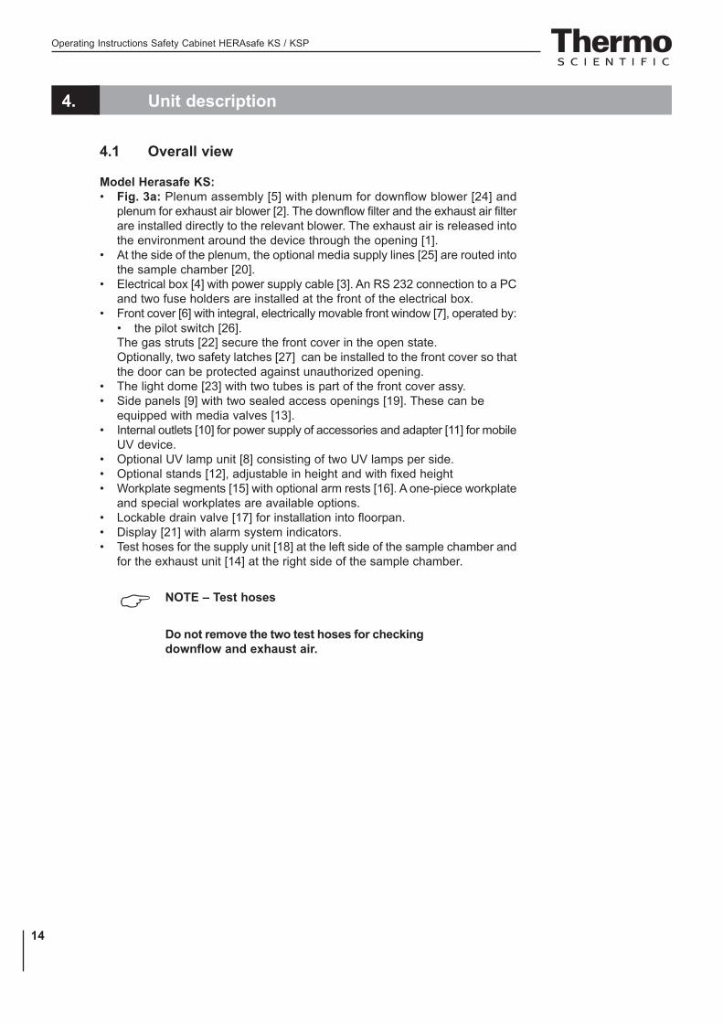
Model Herasafe KS:• Fig. 3a: Plenum assembly [5] with plenum for downflow blower [24] and
plenum for exhaust air blower [2]. The downflow filter and the exhaust air filterare installed directly to the relevant blower. The exhaust air is released intothe environment around the device through the opening [1].
• At the side of the plenum, the optional media supply lines [25] are routed intothe sample chamber [20].
• Electrical box [4] with power supply cable [3]. An RS 232 connection to a PCand two fuse holders are installed at the front of the electrical box.
• Front cover [6] with integral, electrically movable front window [7], operated by:• the pilot switch [26].The gas struts [22] secure the front cover in the open state.Optionally, two safety latches [27] can be installed to the front cover so thatthe door can be protected against unauthorized opening.
• The light dome [23] with two tubes is part of the front cover assy.• Side panels [9] with two sealed access openings [19]. These can be
equipped with media valves [13].• Internal outlets [10] for power supply of accessories and adapter [11] for mobile
UV device.• Optional UV lamp unit [8] consisting of two UV lamps per side.• Optional stands [12], adjustable in height and with fixed height• Workplate segments [15] with optional arm rests [16]. A one-piece workplate
and special workplates are available options.• Lockable drain valve [17] for installation into floorpan.• Display [21] with alarm system indicators.• Test hoses for the supply unit [18] at the left side of the sample chamber and
for the exhaust unit [14] at the right side of the sample chamber.
NOTE – Test hoses
Do not remove the two test hoses for checkingdownflow and exhaust air.

Operating Instructions Safety Cabinet HERAsafe KS / KSP
15
4. Unit description
Fig. 3aOverall view / Model Herasafe KS

Operating Instructions Safety Cabinet HERAsafe KS / KSP
16
4. Unit description
Model Herasafe KSP:• Fig. 3b: Stand [5] with integral prefilter housing [6].• Filter inserts [2] for the prefilter housing. The number of supplied filter
inserts depends on the width of the device. To protect from liquid residues,the filter inserts are oriented slightly sloping from the device backpanel toform a drain duct to the floorpan [3].The filter plates [4] have tongues and grooves and are inserted in anoverlapping pattern from right to left.
• Membrane sleeve or opening for filling with aerosol for testing the filter of thedownflow unit [1] at the left side of the sample chamber and of the exhaustair unit [7] at the right side of the sample chamber.
Fig. 3bOverall view / Model Herasafe KSP

Operating Instructions Safety Cabinet HERAsafe KS / KSP
17
4. Unit description
4.2 Safety system
The safety system comprises a combination of protective and alarm systemsthat ensure maximum personal and material protection.
Safety systems:• Vacuum-sealed air system
A vacuum-sealed air system in combination with HEPA filters for downflowand exhaust air forms the basis of the safety system for personal andmaterial protection.
• Personal protectionAir aspired from the exterior along the entire working opening at a constanthigh velocity prevents that: • agents may leak through the working opening of the chamber.As the exterior air pressure around the unit exceeds the pressure of theinternal air system (vacuum sealing), it is ensured that: • agents cannot be released to the exterior in the case of a leak in the
cabinet housing.• Material protection
A steady airflow within the air system ensures that:• a constant downflow allows the HEPA filters to remove contaminants
so that the samples are always surrounded by ultrapure air,• harmful particles are not carried over through the sample chamber
(protection from cross-contamination).• HEPA filters
The downflow (i.e. the air circulating within the device) and the exhaust air(air that is released to the exterior) are cleaned by HEPA filters (HEPA = HighEfficiency Particulate Air Filter).For version Herasafe KSP, a prefiltering system is used to increase the fil-ter efficiency and to protect the exhaust air and downflow systems.
• Safety lockoutTo protect from UV radiation, the optional UV disinfection routine can be runonly if the front opening is closed. During UV disinfection, the front openingsafety lockout is activated and prevents harmful UV radiation from beingemitted from the sample chamber.
Warning system:• Airflow monitoring
Airflow monitoring determines the velocity of the airflow in the sample chamberas well as the inflow velocity of the air aspired from the exterior through theworking opening. As soon as airflow velocities move above or below aspecified safety value, a signal is transmitted to the alarm system.
• Visual and audible alarm systemThe warning system constantly monitors the safety-relevant device functions:• Inflow velocity of the air aspired from the exterior,• downflow velocity,• working position of the front window.If the warning system detects changes to one of these device functions, itissues:• an audible and a visual alarm signal.

Operating Instructions Safety Cabinet HERAsafe KS / KSP
18
4. Unit description
• Position monitoringThe position sensors monitor the position of the frontcover as well as the movement of the front window; it willindicate when the front window is in the working position.
• Performance FactorThe Performance Factor (PER) is a value that indicates thesafety state of the safety cabinet. This value is calculatedfrom data determined by the safety system and fromvalues captured empirically by service personnel duringsafety checks. This data is entered into a parameter list ofthe control software and interconnected. The result can beindicated by the display.
4.3 Filter system
Model Herasafe KS:Fig. 4a: The filter system consists of two HEPA filters [2] and[5] for the circulating air and for the exhaust air and of a coarsefilter for the aspired air.
HEPA filters: Room air [10] is drawn into the samplechamber through the working opening. In the air duct, roomair and the downflow within the chamber [7] are then blendedto make up the blend air [9]. The blend air is then:• filtered proportionally by the downflow filter [5] and
supplied as ultrapure air [6] evenly into the sample chamberof the device,
• filtered by the exhaust air filter [2] and released asultrapure air [1] to the exterior of the device.
Inlet air protection: The air duct between the sample chamberand the device plenum has an inlet air protection [8] below theworking surface to prevent coarse particles from entering theplenum where they may impair blower [3] und [4] and filterfunctions.
Fig. 4aFilter system with downflowfilter and exhaust air filter /
model Herasafe KS
Operating Instructions Safety Cabinet HERAsafe KS / KSP
19
4. Unit description
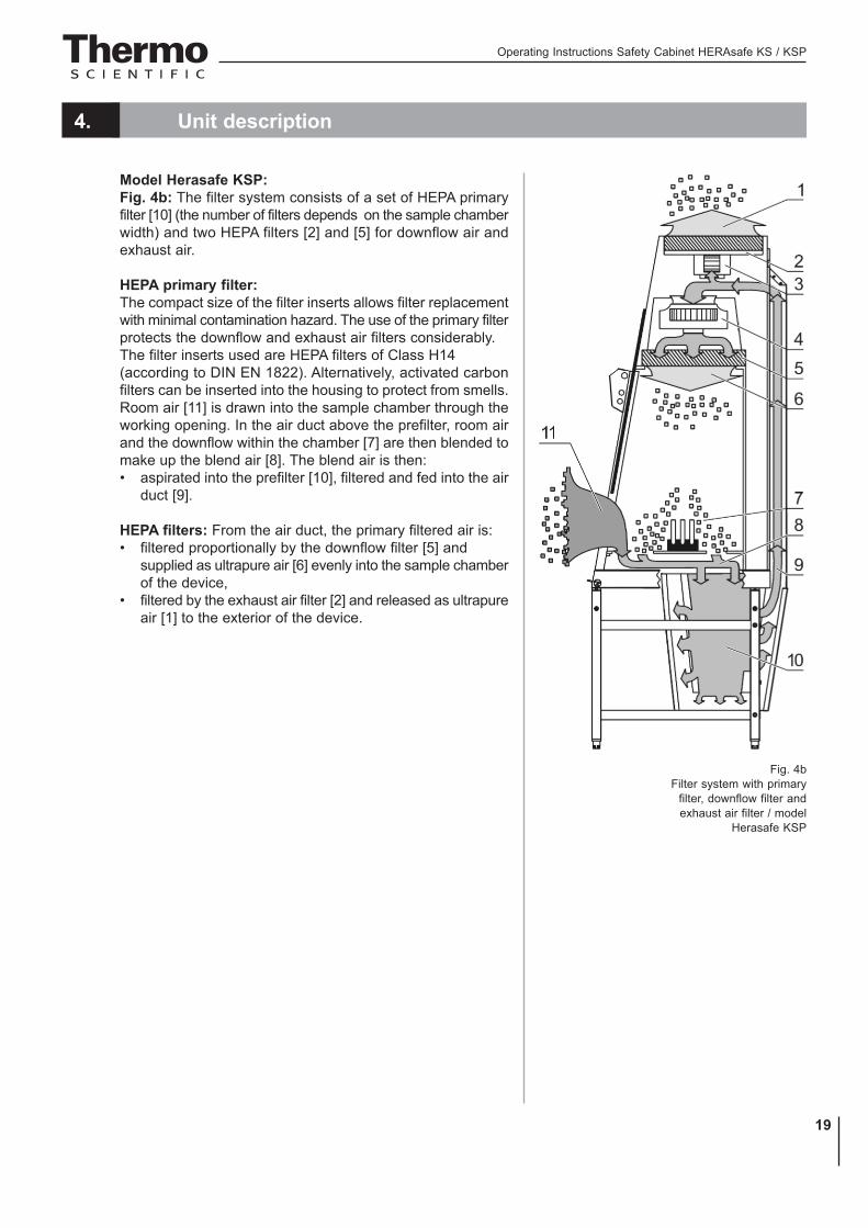
Model Herasafe KSP:Fig. 4b: The filter system consists of a set of HEPA primaryfilter [10] (the number of filters depends on the sample chamberwidth) and two HEPA filters [2] and [5] for downflow air andexhaust air.
HEPA primary filter:The compact size of the filter inserts allows filter replacementwith minimal contamination hazard. The use of the primary filterprotects the downflow and exhaust air filters considerably.The filter inserts used are HEPA filters of Class H14(according to DIN EN 1822). Alternatively, activated carbonfilters can be inserted into the housing to protect from smells.Room air [11] is drawn into the sample chamber through theworking opening. In the air duct above the prefilter, room airand the downflow within the chamber [7] are then blended tomake up the blend air [8]. The blend air is then:• aspirated into the prefilter [10], filtered and fed into the air
duct [9].
HEPA filters: From the air duct, the primary filtered air is:• filtered proportionally by the downflow filter [5] and
supplied as ultrapure air [6] evenly into the sample chamberof the device,
• filtered by the exhaust air filter [2] and released as ultrapureair [1] to the exterior of the device.
Fig. 4bFilter system with primary
filter, downflow filter andexhaust air filter / model
Herasafe KSP
Operating Instructions Safety Cabinet HERAsafe KS / KSP
20
4. Unit description
4.4 Controls and display
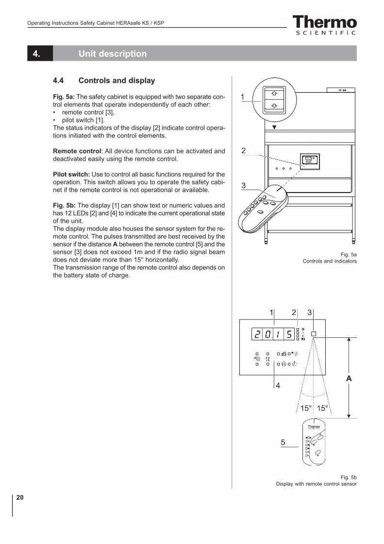
Fig. 5a: The safety cabinet is equipped with two separate con-trol elements that operate independently of each other:• remote control [3],• pilot switch [1].The status indicators of the display [2] indicate control opera-tions initiated with the control elements.
Remote control: All device functions can be activated anddeactivated easily using the remote control.
Pilot switch: Use to control all basic functions required for theoperation. This switch allows you to operate the safety cabi-net if the remote control is not operational or available.
Fig. 5b: The display [1] can show text or numeric values andhas 12 LEDs [2] and [4] to indicate the current operational stateof the unit.The display module also houses the sensor system for the re-mote control. The pulses transmitted are best received by thesensor if the distance A between the remote control [5] and thesensor [3] does not exceed 1m and if the radio signal beamdoes not deviate more than 15° horizontally.The transmission range of the remote control also depends onthe battery state of charge.
Fig. 5aControls and indicators
Fig. 5bDisplay with remote control sensor

Operating Instructions Safety Cabinet HERAsafe KS / KSP
21
4. Unit description
4.5 Sample chamber access
Front cover:The sample chamber of the device is accessible via two modes:Fig. 6a: Manual opening of the front cover [2] allows accessto the complete sample chamber width with an opening heightC. It is generally needed for decontamination and introductionof larger accessories.
NOTE – Front cover lockout!
The front cover is equipped with a safety lock-out and can only be opened in standby mode,i.e. when the front window is completelyclosed.
Optional equipment:As an option, the front cover of both versions can be equip-ped with a safety feature: Two safety latches at the left and rightframe struts secure the front cover from unauthorized opening.With this equipment, the function of the pilot switch is overriddenby a safety bezel so that only the remote control can be usedto access the sample chamber.If the remote control is faulty, the safety bezel can be unscrewedand the device can be operated using the pilot switch (see Sec-tion 6.4).
Front window:Fig. 6b: The electrically operated front window [1] is made ofmulti-layer safety glass and integral to the front cover frame.It can be raised to a maximum opening height B (480 mm). Toaccess the sample chamber during the work process, the frontwindow must stay in the work position with opening height A(200 mm).
CAUTION – Front window movement!
Do not attempt to move the front windowmanually as otherwise the motor drive may bedamaged.
Lowering the front window when the device is deenergized:The safety feature (optional) is backed up by a battery. Shoulda power failure occur, the pilot switch (see Section 6.4) can beused to lower the front window completely.
Fig. 6aAccess through front cover
Fig. 6bAccess through front window

Operating Instructions Safety Cabinet HERAsafe KS / KSP
22
4. Unit description
4.6 Device interfaces
Fig. 7a: The standard equipment includes the outlets [10] for internal power supplyas well as the openings [8] on both sides for routing of cables and hoses. All othersupply connections are available as options.Power supply connection: The connection to the power supply system isachieved through a cable with grounding plug [2] at the rear of the electrical box.Contact connection: The front of the box has an RS 232 interface [3] for theconnection to a PC as well as two fuse holders for 5A miniature fuses:[4] for (L),[5] for (N).Internal power supply: There are two electrical outlets (5A) [10] and one UVdisinfection adapter (optional) [9] located in the side walls.Media valves: There are two sealed feed throughs [8] on each side. These maybe used for installation of media valves [7].Media supply lines: Additionally, media can be supplied into the sample chamberthrough three pipes. The inlets [1] are located on top of the housing, theoutlets [6] are placed at the sample chamber backpanel.
Fig. 7aSupply interfaces

Operating Instructions Safety Cabinet HERAsafe KS / KSP
23
4. Unit description
Disinfection adapter (optional), Fig. 7a: The disinfectionadapter [9] is used to connect a mobile UV radiation device.The adapter is connected to the device control, the UVdisinfection routine with a mobile UV device may be controlledwith the remote control.
Media connections (optional): The media supply unitconsists of three pipes that are routed into the sample chamberthrough the top of the unit. The inlet connections [1] andoutlet connections [6] with thread (R 3/8"), e.g. for media valves[7], are preinstalled and equipped with a sealing plug.The media connections are universal-type connections. Twoequipotential bonding connections are installed at the top ofthe unit and at the stand.
Caution – Combustible gas!
If a gas burner is to be operated in the samplechamber, an appropriate shut-off device for thegas supply system (shut-off valve, solenoidvalve) must be installed.Use only laboratory safety burners in thesample chamber.
External systems: A failure detection systems or gas supplysolenoid valves may be connected to the safety cabinet control.The unit may also be connected to an external ventilationsystem.
4.7 Sample chamber illumination
Fig. 7b: The work space illumination [2] is equipped with twofluorescent tubes that are installed behind the light dome [3].
Fig. 7bSample chamber illumination

Operating Instructions Safety Cabinet HERAsafe KS / KSP
24
4. Unit description
4.8 UV lamp unit
Fig. 8: The UV lamp unit consists of two lamp housings [2]with two UV lamps each [1] that are integral to the side walls.Both lamp housings are protected by a stainless steel cover[3].By cross-radiation of the UV units, all surfaces will bedisinfected as the shadow zone is reduced.The operating time of the UV lamps is preset.
NOTE – Protection from UV radiation
As a protection from harmful UV radiation, theUV lamps can only be activated if the frontwindow is completely closed.
4.9 Working area
The standard equipment comprises the segmented workplatefor the models HERAsafe KS and HERAsafe KSP. Specialworkplates are available as optional accessories.The workplates or workplate segments are placed onto theframe above the sample chamber floorpan using twosubmerging wire straps as handles.
Fig. 9: The working area A for perfect material protectionextends over the entire width B and depth C of the workplate.The two arm rests [3] are positioned at a distanceD (20 cm) to each other centrically on the workplate [1] or onthe workplate segments. The armrests are installed to thesecond perforation line [2] of the workplate.
NOTE – Spilling liquid
(model HERAsafe KSP only)
If larger quantities of liquid are spilled acciden-tally while working with the model HERAsafeKSP, the segmented filters installed below theworking surface must be checked, and, if re-quired, the safe functioning of the device hasto be inspected by qualified service personnel.
Fig. 8 UV lamp unit
Fig. 9Working area on the workplate, armrests

Operating Instructions Safety Cabinet HERAsafe KS / KSP
25
5. Start-up
5.1 Initial operation
Prior to initial operation, the safety cabinet must be subjectedto an installation test. Correct assembly and installationperformed by the operator are essential for good start-up.
Model Herasafe KSP:Upon the initial connection to the power supply system, thedevice control of version Herasafe KSP starts an automatic ca-libration routine to determine the parameters for the safety sys-tem of the device.
NOTE – Calibration routine
The calibration routine is no substitite for theinstallation check performed by the servicepersonnel.
5.2 Installing unit and accessories
Model Herasafe KS:Device without stand:• Place the device without stand onto a sufficiently stable
substructure so that the weight of the device frame doesnot rest upon the floorpan.
• Remove the protective foil from the floorpan.
Device with stand:To assemble the (optional) stand and to install the device frameto the stand:1. Fig. 10a: Slide the two crossmembers [2] onto the retaining
angles [3] of the sidemembers [1]. Secure the crossmembersto the two sidemembers using the screws [4].
2. To attach the device frame [5] to the stand [7], install fourAllen screws [6] loosely into the corresponding threadedholes at the underside of the device.
3. Place the safety cabinet [1] onto the stand so that theAllen screws [6] pass through the corresponding holes [8]of the retaining tabs [10].
4. Push the device frame [5] in the grooves [9] of the retainingtabs [10] all the way to the stop.
5. Tighten the four Allen screws [6].
Fig. 10aStand installation model
Herasafe KS

Operating Instructions Safety Cabinet HERAsafe KS / KSP
26
5. Start-up
Model Herasafe KSP:Fig. 10b: The stand [3] and the prefilter housing form anassembly. To facilitate the installation of the device frame [1],the stand is equipped with a lifting mechanism.The four columns [7] of the stand have threaded rods [6] ontowhich the device frame can be placed and lowered.1. Fig. 10b: Unscrew the threaded rods from their hex disks
[5] by approx. 10 cm and make sure their height is identi-cal on all four columns.
2. Place the safety cabinet onto the threaded rods. Check tosee whether each guide pin [4] is seated perfectly in itsreceptacle at the lower device frame.
3. Screw in each threaded rod at its column in short, evenintervals all the way to the stop of the hex disk.
NOTE – Leveling the device
To level the device, do not use the liftingmechanism but only the adjustable stands ofthe device.
4. Align the working area of the safety cabinet:Place a bubble level onto the workplate and rotate thestands [2] of the stand using a 24-mm wrench until theworkplate is exactly horizontal in all directions. For the ver-tical alignment of the device stands, proceed from left to rightand from rear to front.
Fig. 10bStand installation model
Herasafe KSP
Operating Instructions Safety Cabinet HERAsafe KS / KSP
27
5. Start-up
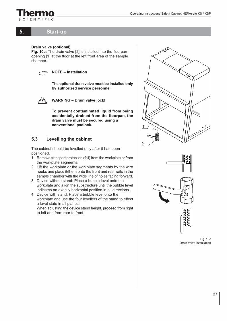
Drain valve (optional)Fig. 10c: The drain valve [2] is installed into the floorpanopening [1] at the floor at the left front area of the samplechamber.
NOTE – Installation
The optional drain valve must be installed onlyby authorized service personnel.
WARNING – Drain valve lock!
To prevent contaminated liquid from beingaccidentally drained from the floorpan, thedrain valve must be secured using aconventional padlock.
5.3 Levelling the cabinet
The cabinet should be levelled only after it has beenpositioned.1. Remove transport protection (foil) from the workplate or from
the workplate segments.2. Lift the workplate or the workplate segments by the wire
hooks and place it/them onto the front and rear rails in thesample chamber with the wide line of holes facing forward.
3. Device without stand: Place a bubble level onto theworkplate and align the substructure until the bubble levelindicates an exactly horizontal position in all directions.
4. Device with stand: Place a bubble level onto theworkplate and use the four levellers of the stand to effecta level state in all planes.When adjusting the device stand height, proceed from rightto left and from rear to front.
Fig. 10cDrain valve installation

Operating Instructions Safety Cabinet HERAsafe KS / KSP
28
5. Start-up
5.4 Activating the remote control
The remote control operates on two batteries with the followingspecifications:• 1.5 V alkaline cell (AAA,Type LR 03)
Installing the batteries:1. Fig. 11: Open the lid [4] of the battery housing at the bot-
tom of the remote control by inserting a pointed instrumentinto the notch [1] and prying the lid off.
2. Insert the batteries [3]. The positive and negative poles aremarked at the bottom of the battery housing.
3. Check the position of the coding switch [2]. If the switch isnot set to position 1, rotate it to that position.
4. Insert the two hinges of the lid into the joints at the batte-ry housing and slightly press onto the lid so that the retai-ning clip engages.
Functional check:After the safety cabinet has been connected to the power supplysystem, the function of the remote control can be checked byswitching on the light within the sample chamber. Point the re-mote control toward the display at the sample chamber back-panel:
Press key
Contamination protection:While the sample chamber is used, protect the remote con-trol against dirt and contamination by using the disposabletransparent cover.
Fig. 11Inserting the batteries

Operating Instructions Safety Cabinet HERAsafe KS / KSP
29
5. Start-up
5.5 Power supply connection
WARNING – High voltage!
Contact with current-carrying components maycause a lethal electric shock.Before connecting the device to the powersupply system, check plug and power supplycable for possible damage.Do not use damaged components to connectthe device to the power supply system!
Establishing the power supply connection:1. Before connecting the device to the power supply system, check to see if the
voltage of the outlet corresponds with the specifications on the nameplateof the device. If the ratings given for voltage (V) and maximum current (A)are not correct, the device must not be connected to the power supplysystem.
2. Connect the grounding plug of the device to a properly grounded and fusedoutlet.• The outlet must be fused separately using a fusible link T 16 A or using
a circuit breaker B 16.3. Make sure that the power cable is routed away from the counterweight and
cable guide. For this purpose, the power cable can be secured to the deviceceiling using the enclosed adhesive bases and cable ties (see installationinstructions).
4. Make sure that the power supply line is not subjected to tensile or compressiveforce.
Installation of the power supply connection:To protect against accidental switch-off, the outlets for the connection to the powersupply must be located outside the normal hand reaching range and must beaccessible only to auhorized personnel. Ideally, the outlets should be installedabove the safety cabinet.
Connecting the equipotential bonding:If the sample chamber is supplied with media (gas, water, etc.), the on-siteequipotential bonding must be connected to one of the premounted threadedbushings either at the top of the housing or at the stand.
Initialization routine:After the unit has been connected to the power supply system, the device controlruns through a start-up initialization routine and switches the functions to the OFFmode. The safety cabinet is now operational and can be operated using theremote control or the pilot switch
Presetting the alarm limits upon initial operation, Herasafe KSP:
NOTE – Presetting the alarm linits
The alarm limits must be set only upon theinitial operation of the device.

Operating Instructions Safety Cabinet HERAsafe KS / KSP
30
5. Start-up
Initial operation:After the initialization routine has been completed, the calibration routine is run(only Herasafe KSP):• The display shows "CAL".• The routine starts automatically when the device control is in the work mode
(sees Section 6.2) and runs for approx 30 minutes. If the airflow is disturbedduring the run time, the routine is cancelled and restarted automatically.
• At the end of the routine, the determined parameters for the alarm limits aresaved.
NOTE – Initial operation
According to applicable national standardsand regulations, the calibration routine is nosubstitute for a start-up performed by anauthorized service technician.
Setting the clock:After the initialization routine has been run, the clock should be set to theappropriate time zone (see Section 6, Operation).
NOTE – Power supply connection
The safety cabinet should remain connectedto the power supply system at all times toensure that settings for the individual unitconfiguration remain active in the memory. Ifthe power supply is interrupted for more than5 minutes, the time must be reset correctly.After the power supply connection has beenreestablished, the system switches to theoperating mode that had been active last.

Operating Instructions Safety Cabinet HERAsafe KS / KSP
31
5. Start-up
5.6 RS 232 interface connection
The RS 232 interface has been designed for a cable connectionwith 9-pin connectors and a contact assignment of 1:1.
Connection of the device:1. Turn PC off.2. Fig. 12: Connect the connector of the serial interface
cable (not comprised in the scope of delivery) to thesocket [1] at the supply interface at the front of theelectrical box.
3. Connect the serial interface cable to an unassignedslot COM 1/COM 2 etc. at the PC.
4. Turn PC on.
Transfer protocol:The interface must be configured as follows:Baud: 9600Data bits: 8Parity: noneStop bit: 1Protocol: noneFIFO–puffer(extended modulation): enabled
Occupancy of conductors:Type of connector [X] : 9-Pin SUB-DPin 2: TxDPin 3: RxDPin 5: GND
5.7 UV connection
Fig. 13: UV disinfection adapter (optional) for an external UVdisinfection unit.Voltage: 230 VCurrent: max. 1,1 AConnectors: [1], [2], [3] and PE-sign
Fig. 12RS 232 interface connection
Fig. 13UV connection

Operating Instructions Safety Cabinet HERAsafe KS / KSP
32
5. Start-up
5.8 Installation test
Do not operate the device before the installation test has been completed.• The installation inspection of the device must be conducted in accordance
with EN 12469 and additionally according to DIN 12980 for Herasafe KSP.The cabinet may be operated as a Class II microbiological safety cabinet,in accordance with EN 12469 / 2000, if the device functions or function patternslisted below were checked and if the test results are within the safety valuetolerances specified in Annex F:• Electrical safety test• Inflow velocity test• Downflow velocity test• Leakage test of HEPA filters• Airflow control test
• A repeat test must also be performed after repairs to the device or aftermajor changes (more than 5 cm) to the location of the device.
• The operator must prepare a test report or request a written test report fromthe authorized test service.
NOTE – Safety warranty
The operational safety of the device,particularly the personal and materialprotection, are guaranteed only if all safetyfunctions of the device have been tested andapproved.Thermo Electron LED GmbH will not warrantthe operational safety if the device is operatedwithout performance of the requiredinstallation test or if the installation test andrepeat test are not performed by adequatelytrained and authorized personnel!
NOTE – Device hygiene
The initial start-up with subsequent installationtest does not include any decontaminationmeasures. For operation in the work process,the sample chamber of the device and theaccessories required for the work processmust be disinfected and cleaned in accordancewith the hygiene guidelines set forth for theapplication.

Operating Instructions Safety Cabinet HERAsafe KS / KSP
33
6. Handling and control
6.1 Display
Fig. 14: The display at the sample chamber backpanel shows• status messages,• parameter input and putput.
6.1.1 Functions of the display components[1] Display segment for numbers and text
Value displaysThe LEDs 2-5 illuminate when the corresponding value is called up:[2] Display time (yellow LED), usually the active standard display[3] Display downflow velocity (yellow LED)[4] Operating hours after last filter replacement (yellow LED)[5] Display Performance Factor (yellow LED)
Function displaysThe LEDs 6-9 illuminate only when the pertaining value is called up:[6] Ventilation reduced (yellow LED)[7] Potential-free contact activated (yellow LED)[8] Internal power supply activated (yellow LED)[9] UV disinfection routine activated (yellow LED)
Status displaysThe LEDs 10/13 and 11/12 show the operating condition of the device as eit-her/or conditions:[10] Front window is not in working position (red LED)[13] Front window is in working position (green LED)[12] Airflow is steady (green LED)[11] Airflow is not steady (red LED)
Fig. 14Functions of the display components
Operating Instructions Safety Cabinet HERAsafe KS / KSP
34
Error code Fault causeER 1 Pressure sensor 1 / supplyER 2 Pressure sensor 2 / exhaustER 4 BUS errorER 5 RAM errorER 6 Error remote control
6. Handling and control
6.1.2 Display during the calibration routineThe routine runs for approx 30 minutes. During this time, the display showsalternatingly cal and the descending time value. If the calibration routine can-not be started due to faults, the display shows cal permanently.
6.1.3 Display in OFF modeIn the OFF mode, the display shows the current time.For the initial start-up of the device, the clock must be set to the correct time zoneand to the corresponding time output (CET mode or AM/PM mode)(see Section 6.3.9).
6.1.4 Display in work modeIn the work mode, the display shows the values of the device data that had beenshown last (see Section 6.3.9.ff):• Time (hours and minutes)• Downflow velocity• Operating hours after last filter replacement• Performance Factor
6.1.5 Power interruptionIf the master PCB of the device detects a power failure or a failure of the po-wer supply, a warning is issued.
Note – Power failure warning
In case of a power failure, the display goes offafter 10 seconds, then an audible alarm signalsounds for about 30 seconds.After this warning, the device is no longeroperative.
The safety feature (optional) allows the complete lowering of the front windowafter a power failure by pressing the pilot switch.
6.1.6 Display and functions after a power failureAfter the power supply has been reestablished after a power failure, the displayshows the values and functions that were last shown prior to the failure.The functions that had been selected last will be continued where they had beeninterrupted.
6.1.7 Failure messagesFailure messages are shown on the display as text/number combinations withthe codes ER 1 to ER 6. If one of these codes appears on the display, contactTechnical Service immediately.
Operating Instructions Safety Cabinet HERAsafe KS / KSP
35
6. Handling and control
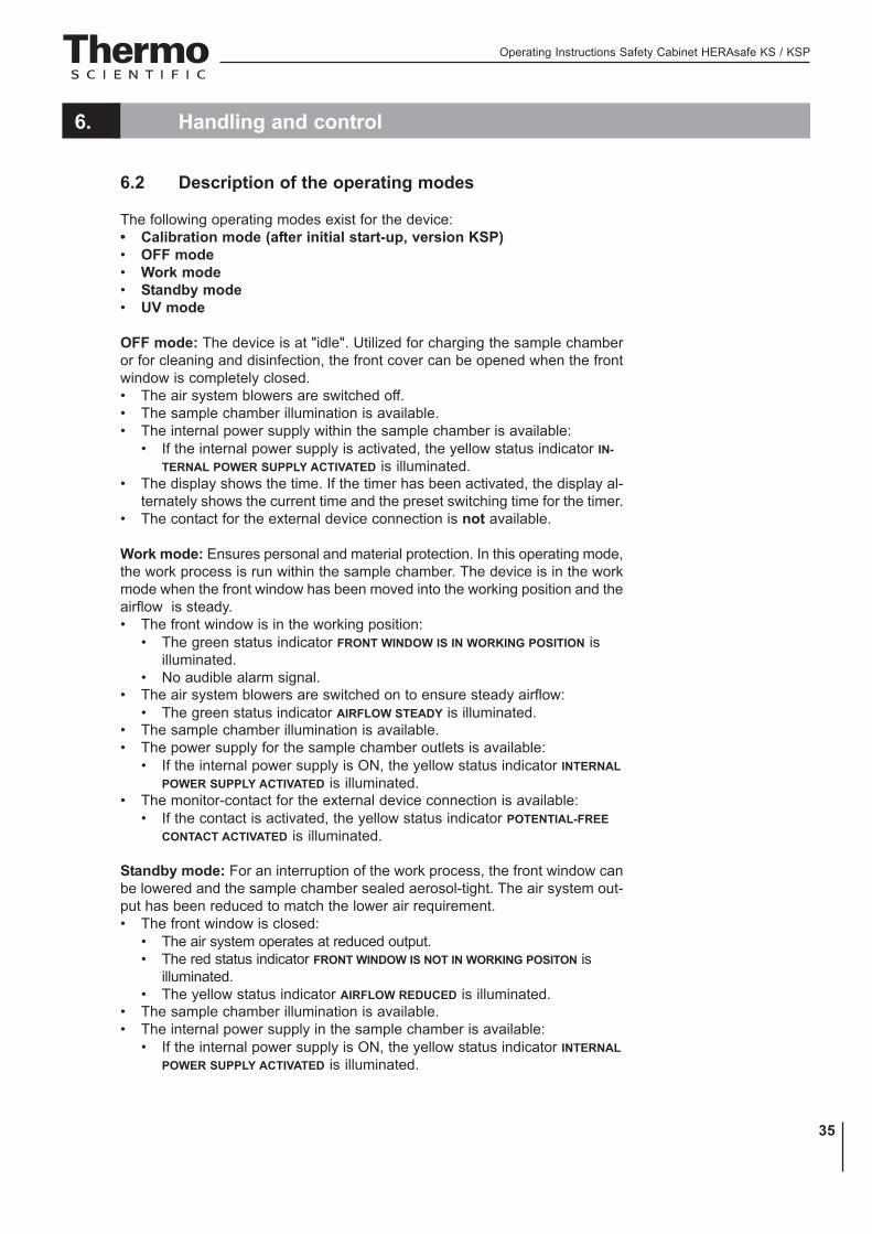
6.2 Description of the operating modes
The following operating modes exist for the device:• Calibration mode (after initial start-up, version KSP)• OFF mode• Work mode• Standby mode• UV mode
OFF mode: The device is at "idle". Utilized for charging the sample chamberor for cleaning and disinfection, the front cover can be opened when the frontwindow is completely closed.• The air system blowers are switched off.• The sample chamber illumination is available.• The internal power supply within the sample chamber is available:
• If the internal power supply is activated, the yellow status indicator IN-TERNAL POWER SUPPLY ACTIVATED is illuminated.
• The display shows the time. If the timer has been activated, the display al-ternately shows the current time and the preset switching time for the timer.
• The contact for the external device connection is not available.
Work mode: Ensures personal and material protection. In this operating mode,the work process is run within the sample chamber. The device is in the workmode when the front window has been moved into the working position and theairflow is steady.• The front window is in the working position:
• The green status indicator FRONT WINDOW IS IN WORKING POSITION isilluminated.
• No audible alarm signal.• The air system blowers are switched on to ensure steady airflow:
• The green status indicator AIRFLOW STEADY is illuminated.• The sample chamber illumination is available.• The power supply for the sample chamber outlets is available:
• If the internal power supply is ON, the yellow status indicator INTERNALPOWER SUPPLY ACTIVATED is illuminated.
• The monitor-contact for the external device connection is available:• If the contact is activated, the yellow status indicator POTENTIAL-FREE
CONTACT ACTIVATED is illuminated.
Standby mode: For an interruption of the work process, the front window canbe lowered and the sample chamber sealed aerosol-tight. The air system out-put has been reduced to match the lower air requirement.• The front window is closed:
• The air system operates at reduced output.• The red status indicator FRONT WINDOW IS NOT IN WORKING POSITON is
illuminated.• The yellow status indicator AIRFLOW REDUCED is illuminated.
• The sample chamber illumination is available.• The internal power supply in the sample chamber is available:
• If the internal power supply is ON, the yellow status indicator INTERNALPOWER SUPPLY ACTIVATED is illuminated.
Operating Instructions Safety Cabinet HERAsafe KS / KSP
36
6. Handling and control
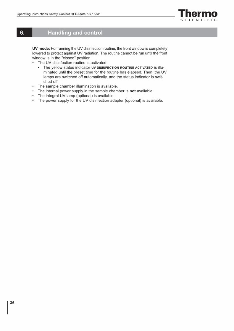
UV mode: For running the UV disinfection routine, the front window is completelylowered to protect against UV radiation. The routine cannot be run until the frontwindow is in the "closed" position.• The UV disinfection routine is activated:
• The yellow status indicator UV DISINFECTION ROUTINE ACTIVATED is illu-minated until the preset time for the routine has elapsed. Then, the UVlamps are switched off automatically, and the status indicator is swit-ched off.
• The sample chamber illumination is available.• The internal power supply in the sample chamber is not available.• The integral UV lamp (optional) is available.• The power supply for the UV disinfection adapter (optional) is available.
Operating Instructions Safety Cabinet HERAsafe KS / KSP
37
6. Handling and control
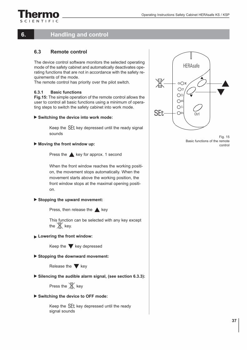
6.3 Remote control
The device control software monitors the selected operatingmode of the safety cabinet and automatically deactivates ope-rating functions that are not in accordance with the safety re-quirements of the mode.The remote control has priority over the pilot switch.
6.3.1 Basic functionsFig.15: The simple operation of the remote control allows theuser to control all basic functions using a minimum of opera-ting steps to switch the safety cabinet into work mode.
Switching the device into work mode:
Keep the key depressed until the ready signalsounds
Moving the front window up:
Press the key for approx. 1 second
When the front window reaches the working positi-on, the movement stops automatically. When themovement starts above the working position, thefront window stops at the maximal opening positi-on.
Stopping the upward movement:
Press, then release the key
This function can be selected with any key exceptthe key.
Lowering the front window:
Keep the key depressed
Stopping the downward movement:
Release the key
Silencing the audible alarm signal, (see section 6.3.3):
Press the key
Switching the device to OFF mode:
Keep the key depressed until the readysignal sounds
Fig. 15Basic functions of the remote
control

Operating Instructions Safety Cabinet HERAsafe KS / KSP
38
6. Handling and control
Availability of functions in the different operating modes: x = available
6.3.2 Moving the front window to the working position
1. Raising or lowering the dront window:
Press, then release the key for approx. 1 second
The red status indicator on the display is illuminated
The audible alarm signal is on.
2. When the front window reaches the working position, the movement is au-tomatically stopped.
The green status indicator on the display is illuminated
The audible alarm signal is off if the airflow is steady.
3. If the movement starts above the working position, the front window must firstbe lowered below the working position and then be raised again. To lowerthe front window:
Keep the key depressed
4. To stop the downward movement:
Release the key
Key
OFF mode Work mode Standby mode
UV mode
X X X X
X X
X X
X X X
X X X
X X X
X X X X
X X
X
Mode

Operating Instructions Safety Cabinet HERAsafe KS / KSP
39
6. Handling and control
6.3.3 Silencing the audible alarm signalWhen the front window is moved out of the working position or when the pres-sure sensors detect a safety-relevant change of the airflow velocities, the cor-responding visual and audible alarm signals are issued. To silence the audiblealarm:
• Press, then release the key
NOTE – Quitting the optical alarm signal!
The optical alarm signals can notbe quitted.They change her status indication only, if thenecessary functions of the device areoperational.
NOTE – Silencing the audible alarm signal!
The audible alarm signal only can be silenced,if the front window is either completely closedor has been moved to the maximum upper ope-ning position.In the working position the audible alarm signalcan not be silenced.
Changing the factory setting:You can change the factory setting so that the audible alarm signals can besilenced (switched off) in any operating mode at any position of the frontwindow. The status is at the display as follows:• P7 0 signal can be silenced• P7 1 signal cannot be silenced
Switch the device to OFF mode:
• Keep the key depressed until the ready signal sounds
Deactivate the factory settings:
• Keep the key depressed for 5 seconds
Silence audible alarm signals:
• Press the key

Operating Instructions Safety Cabinet HERAsafe KS / KSP
40
6. Handling and control
Reestablish the factory settings:
Switch the device to OFF mode:
• Keep the key depressed until the ready signal sounds
Activate the factory settings:
• Keep the key depressed for 5 seconds
6.3.4 Switching the illumination on and offIn each operating mode, the sample chamber illumination can be switched onor off.
1. To switch the illumination on or off:
Press, then release the key
6.3.5 Activating and deactivating the internal power supplyAll outlets in the sample chamber can be activated (power supply on) or deac-tivated (power supply off) simultaneously.
1. To activate the power supply:
Press, then release the key
The yellow status indicator is illuminated.
2. To deactivate the power supply:
Press, then release the key
The yellow status indicator goes off.
6.3.6 Displaying the UV disinfection timeThis value refers to the operating hours of the set run time of the UV disinfec-tion or of the power supply for the UV disinfection adapter (optional). This dis-play function is only available when the front window is not closed. The devicemust be switched to work mode.
1. To display the value:
• Press, then release the key
The time value is output in segments of 30 minutes.
2. To deactivate the value display:
The value display is deactivated automatically after 2-3 seconds.

Operating Instructions Safety Cabinet HERAsafe KS / KSP
41
6. Handling and control
6.3.7 Activating and deactivating the potential-free contact (optional)An external solenoid valve or alarm system that is connected to the safety ca-binet control system can generally be enabled only if the device is operated inthe secure work mode. Enable or disable an external system:
1. To activate the contact:
Press, then release the key
The yellow status display is illuminated.
2. To deactivate the contact:
Press, then release the key
The yellow status display goes off.
NOTE – LED for potential-free contact
If this button is pressed on the remote control,the LED also illuminates if no external alarm sy-stem is connected to the device.
6.3.8 Switching the cabinet to OFF modeThe unit can be switched to OFF mode from any other operating mode:
• Keep the key depressed until the ready signal sounds
6.3.9 Setting the timeThe current time of the time zone in which the unit operates must be set at thestart-up of the safety cabinet. Two different display modes can be selected:• CET mode (24:00 hours)• AM/PM mode (12:00 hours)When the time is to be set, the device must be in the OFF mode.
1. Set the time:
Keep the . key depressed until the two-digit hour disply flashes.
The minute display shows either A, P or no value (CET time display).The time zone is set at the same time as the hour value: First, setthe time zone (sequence: CET, A, P), then set the exact hour value.
2. While increasing or decreasing the hour value in increments, set thetime zone:
Press, then release the or the key
3. Scroll through values:
Keep the or the key depressed

Operating Instructions Safety Cabinet HERAsafe KS / KSP
42
6. Handling and control
If the keys are depressed for approx. 2 or 3 seconds, a higher scrollspeed is selected.
4. Store the hour and time zone setting:
Press the . key
The function switches to minute display (flashing).
5. Set the minutes:
Press, then release the or the key
6. Scroll through values:
Keep the or the key depressed
If the keys are depressed for approx. 2 or 3 seconds, a higher scrollspeed is selected.
7. Store the minute value:
Press, then release the . key
The display shows the time.
NOTE – Calling up device data!
The following data can be called up insuccession:
• Time (hours/minutes)• Downflow velocity• Operating hours after last filter
replacement• Performance Faktor
To call up values in succession:• Press, then release the . key for each
value
The following three sections contain detailedinformation about displaying values.
6.3.10 Displaying the downflow velocityThe sensor system of the device continuously monitors the downflow velocityof the airstream in the sample chamber. The currently determined value (m/s)can only be called up in the work mode.
• To display the velocity value:
Press the . key repeatedly until the yellow E LED illuminates.

Operating Instructions Safety Cabinet HERAsafe KS / KSP
43
6. Handling and control
6.3.11 Displaying the operating hours of the HEPA filtersThe filter total operating hours after the last filter replacement can be display-ed. Upon each filter replacement, the hours are reset to zero.
1. To display the total operating hours:
Press the key repeatedly, until the yellow status indicator on the display is illuminated.
2. The value indicates the full hours.
6.3.12 Displaying the Performance FactorThe Performance Factor (PER) is a value that indicates the safety state of thesafety cabinet.This value is calculated from data determined by the cabinet safety system andfrom values captured empirically by service personnel during safety checks. Thisdata is entered into a parameter list of the control software and interconnected.The result can be indicated by the display.
1. To call up the PER:
Press the . key repeatedly until the yellow status indicator on the display is illuminated.
The PER is displayed as an integer.
2. To evaluate the PER:
Number in the 100 to 60 range: The safety cabinet is operationallysafe. Personal and material protection is ensured.
Number in the 59 to 30 range: The safety cabinet is still operatio-nally safe. Personal and material protection is ensured.The safetysystem should be checked.
Number in the 29 to 0 range: The safety of the device may be im-paired. The failure causes must only be repaired by authorized ser-vice personnel. Contact Technical Service.
NOTE – Calling up value!
The value should only be called up, when theairflows have stabilized itself after a lead timeof approx. 20 min.

Operating Instructions Safety Cabinet HERAsafe KS / KSP
44
6. Handling and control
6.3.13 Setting and activating the timerThe timer function allows you to switch the safety cabinet from the OFF modeto the work mode at a predetermined time. The timer can only be set when thedevice is in the OFF mode.
1. To set the switching time:
Keep the key depressed until the ready signal sounds
The display flashes the two-digit hour display.
2. Increase or decrease the hour value in increments:
Press, then release the or the key
3. Scroll through the value display:
Keep the or the depressed
If the keys are depressed for approx. 2 or 3 seconds, the higherscroll speed is selected.
4. Store the hour setting:
Press, then release the . key
The function switches to minute display (flashing).
5. Set the minute value:
Press, then release the or the key
6. Scroll through the value display:
Keep the or the depressed
If the keys are depressed for approx. 2 or 3 seconds, the higherscroll speed is selected.
7. Store the minute value and activate the timer:
Press, then release the . key
The status display flashes. After a moment, the display showsthe current time again. When the value is stored, the timer is auto-matically activated.
If the setting is not stored, the switching time will be reset to the original valueafter approx. 15 seconds.

Operating Instructions Safety Cabinet HERAsafe KS / KSP
45
6. Handling and control
NOTE – Activating the timer!
If the timer is to be activated without a priorchange of the time values, the procedure abo-ve is performed and the existing time valuesare confirmed:
Press, then release the . key for eachvalue.
After the minute value has been confirmed, thetimer has been activated.
NOTE – Timer function!
The timer can not be used as a start routinethat calls up its function automatically.It must be reactivated separately for each de-ferred device start.
6.3.14 Deactivating the timerIf the device was started at a preset time, the timer function is also deactivatedautomatically. The deferred start can therefore be cancelled only while the de-vice is still in the OFF mode.
• To deactivate the timer function for starting the device:
Keep the key depressed until the ready signal sounds
The safety cabinet changes to the work mode.
The status indicator illuminates continuously, and the displayshows the current time.
Operating Instructions Safety Cabinet HERAsafe KS / KSP
46
6. Handling and control
6.3.15 Setting the UV disinfection timeDepending on the equipment option of the cabinet, this setting is used to:• determine the disinfection time of the optional UV lamps in the side walls or• set the time for the power supply of a mobile UV device at the UV adapter.Factory setting is one hour. The time can be set within a range between 0 and24 hours in increments of 30 minutes each. The unit must be in the work mode(the front window must not be closed). For each following start of the UV dis-infection, the routine is run with this preset time value.
1. Select the function:
Keep the key depressed until the ready signal sounds
The display flashes the run time that had been selected last.
2. Set or change the disinfection time. To increase the value in incre-ments:
Press, then release the or the key
3. Scroll through the value display in increments of 30 minutes:
Keep the or the key depressed
4. Store the setting:
Press, then release the . key
If the setting is not stored, the disinfection time will be reset to the original va-lue after approx. 15 seconds.
6.3.16 Starting the UV disinfectionThe UV disinfection can only be started if the front window is completely lowered(standby mode). Depending on the equipment of the unit version, this functionis used to:
• switch on the optional UV lamps in the side walls or
• activate the power supply for the outlets of the mobile UV device.
• Start the routine:
Keep the key depressed until the ready signal sounds
The display alternately shows the Text dis and the remaining disin-fection time in hours and minutes.
The yellow status indicator is illuminated.
After the disinfection time has elapsed, the current time is displayed.

Operating Instructions Safety Cabinet HERAsafe KS / KSP
47
6. Handling and control
6.3.17 Cancelling the UV disinfectionWhile the UV disinfection routine is run, it can be interrupted at any time.
1. Cancelling the routine:
• Press, then release the key
The status indicator goes off.
2. The display shows the current time.
6.3.18 Activating the stop watchThe stop watch function starts a countdown for a preset time (max. 99 min and59 s) and issues an audible signal when the set time has elapsed. The signalcannot sound if some other device function has already caused an alarm. Thefunction can only be avtivated if the device is in the work mode.
1. Select the stop watch function:
Keep the key depressed until the ready signal sounds
2. Set the minutes (0 - 99) in increments:
Press, then release the or the key
3. Scroll through the value display:
Keep the or the depressed
If the keys are depressed for approx. 2 or 3 seconds, the higherscroll speed is selected.
4. Store the minute setting:
Press, then release the . key
The function switches to second display (flashing).
5. Set the second value (0 - 59):
Press, then release the or the key
6. Scroll through the value display:
Keep the or the depressed
If the keys are depressed for approx. 2 or 3 seconds, the higherscroll speed is selected.
7. Store the setting and start the stop watch:
Press, then release the . key

Operating Instructions Safety Cabinet HERAsafe KS / KSP
48
Fig. 16Basic functions of the
pilot switch
6. Handling and control
8. Indication of the function:
The predefined time value counts to zero.
6.4 Pilot switch
Fig. 16: If the remote control is not available, the basic func-tions required for the operation of the device can be controlledwith the pilot switch:• switch the device on,• Raising and lowering the front window,• silencing the audible alarm signal,• switching the device to OFF mode.
6.4.1 Moving the front window:The movement of the front window is controlled by depressingthe pilot switch control element with the corresponding arrowsymbol.1. To raise the window, press the control element [1]. When
the front window reaches the working position, the move-ment stops automatically. If the movement starts above theworking position, the front window stops at the maximalopening position.
2. To stop the upward movement, release the control element.3. To lower the window, keep the control element [2]
depressed.4. To stop the downward movement, release the control
element.
NOTE – Switching functions (on/off)
If the device is started with the pilot switch, thechamber illumination is switched on.If the device is switched off with the pilotswitch, the chamber illumination is also swit-ched off.
5. If the front window is not in the working position,• the red status indicator FRONT WINDOW IS NOT IN WOR-
KING POSITION is illuminated.• the audible alarm signal can be silenced (i.e. swit-
ched off) if the front window is either completelyclosed or has been moved to the maximum upperopening position.
6. When the front window reaches its working position, themovement stops automatically:• The green status indicator FRONT WINDOW IS IN WOR-
KING POSITION is illuminated.• The audible alarm signal is switched off.
Operating Instructions Safety Cabinet HERAsafe KS / KSP
49
6. Handling and control
6.4.2 Silencing the audible alarm signal:1. Move the front window to the upper and lower end positions.2. Release the control element.3. Press, then release the control element. The audible alarm
signal remains off.
6.4.3 Switching the device to OFF mode1. Move the front window to the upper and lower end positions.2. Release the control element.3. Keep the previously actuated control element depressed until the ready si-
gnal sounds.
NOTE – Switch-off function
If the device is switched to the OFF mode withthe pilot switch, the chamber illumination isswitched off. The device-internal power sup-ply remains in the last functional state that ithad been switched to.
Operating Instructions Safety Cabinet HERAsafe KS / KSP
50
7. Operation
7.1 Hygiene preparations for the sample chamber
The sample chamber surfaces and the accessories required for the workprocess must be disinfected and cleaned in accordance with the hygieneguidelines set forth for the application.
7.2 Preparing the sample chamber
Installing the accessories:1. Lower the front window completely.2. Open the front cover or move the front window into the maximum opening
position.3. Position the accessories in the working area of the workplate.4. Close the front cover.5. Move the front window to its working position and wait until the airflow has
stabilized.
CAUTION – Operational safety!
The personal and material protection is ensuredonly if the airflow system of the device isworking properly.If the alarm system issues failure messageswhen the front window is in the workingposition, stop all applications that may releaseharmful aerosols!
NOTE – Application of cystostatic agents
For the application of cystostatic agents, thelowered single-part working plate must beused. Application of cystostatic agents.
6. Then place samples into the chamber.7. To interrupt the work process or for extensive experiment cycles without
manual interference, switch the device to standby mode. When the workingopening is completely closed, the safety cabinet is sealed aerosol-tight.
7.3 Response to failure messages
Failure messages are displayed in form of text/number combinations with a codebetween ER 1 and ER 6 (see chapter 6.1.6). If one of these codes is displayed,contact the Technical Service immediately.To isolate the cause of the failure, the operating personnel must perform onlythe following tests and measures:• Check to see if the exhaust air opening on top of the cabinet is blocked.• Ensure that the on-site exhaust air system is activated.• Close doors and windows in the laboratory to prevent drafts.• Switch off devices in the vicinity of the safety cabinet that cause air
turbulence or emit excessive heat.• Open flames in the sample chamber may impair airflow conditions.

Operating Instructions Safety Cabinet HERAsafe KS / KSP
51
7. Operation
7.4 Work rules
The observance of work rules ensures a minimum of operational safety whenhandling the safety cabinet.
Before starting an operation:• Take off jewelry.• Put on required personal protective gear, e.g. hand, face, or body protection.• Clean and disinfect sample chamber surfaces at regular intervals.
During operationan:• Place samples only with in the defined work area of the workplate.• Do not place unnecessery items into the sample chamber.• Use only disinfected and cleaned accessories for the work process.• Do not cause air turbulence, by quick hand, arm or body movement in the
sample chamber or in front of the work opening.• Do not place accessories into the sample chamber that cause air turbulence
or emit excessive heat.• Do not block air circulation at the ventilation slots of the workplate.
Sitting posture during work:Fig. 17: To prevent risks to health, a height-adjustable workingchair with an adjustable seat back should be used duringextended work periods at the safety cabinet.A When the forearm rests on the armrest, is should be in an
almost horizontal position.B When the thigh is in a horizontal position, the angle between
thigh and lower leg should exceed 90°.
To ensure a compensation between floor and sitting height, aFootrest (optional accessory) should be used.
After finishing an operation:• Remove samples from the sample chamber and store them
properly.• Clean and disinfect the sample chamber surfaces,
including the workplate and the floorpan. Clean anddisinfect all accessories.
Fig. 17Sitting posture
Operating Instructions Safety Cabinet HERAsafe KS / KSP
52
8. Shut-down
8.1 Interrupting an operation
To interrupt a work process, the device is switched to the OFF mode.1. Remove all samples from the safety cabinet and store them properly.2. Remove accessories from the sample chamber and clean and disinfect them.3. Clean and disinfect the sample chamber surfaces, the workplate, and the
floorpan.4. Switch the device to OFF mode by keeping the ON key depressed until the
indicators go off (a dot in the right display segment remains as a voltage signalindicator).
8.2 Shutting the unit down
If the unit is not to be used or stored for an extended period of time, it must becompletely decontaminated.
CAUTION – Decontamination measures!
To shut the device down, the sample chambermust be disinfected completely and theplenum, including the filters, must be sterilizedusing formaldehyde.
1. After the device has been decontaminated, close the front window completely.2. Disconnect the device from the power supply system.
NOTE – Removing the batteries!
To prevent the batteries from leaking and toprevent their contacts from oxidizing during ex-tensive operation intermissions, remove thebatteries from the remote control and storethem in a dry place.The nickel-metalhybrid battery for the safetyfeature "Lower front window" is leakproof andcan remain installed.

Operating Instructions Safety Cabinet HERAsafe KS / KSP
53
9. Cleaning and decontamination
9.1 Decontamination procedure
Several procedures can be applied for decontaminating the safety cabinet. Whichprocedure is selected, depends on:• the potential risk imminent in the agents,• the degree of purity required by an experiment or by a work process.
Possible decontamination procedures:Wipe/spray disinfection: is the standard disinfection procedure for cabinetsused for microbiological experiments.
UV disinfection: is particularly suited as an intensifying additional disinfectionafter a wipe/spray disinfection.
Sterilization with steam: can be used for treating the removable stainless steelcomponents. Examples of autoclavable components are the bezels of the UVlamps, the workplate or workplate segments and the armrests.
Disinfection with formaldehyde: can be performed if a sterile scmplechamber is required for the work process. This sterilization procedure ismandatory:• when filters are replaced,• when the device is shut down,• when the device is discarded.
9.2 Wipe/spray disinfection
The wipe/spray disinfection is performed in three stages:• Predisinfection,• cleaning,• final disinfection
Recommended disinfectants:
NOTE – Compatibility
Chloride-containing disinfectants may damagesome surfaces. Therefore, use only disinfectantsthat do not contain chloride!Disinfectants with an alcohol content of morethan 70 % may cause embrittlement of plasticcomponents after extended esposure. Use onlydisinfectants with a low alcohol content. Whenusing a disinfectant with an alcohol contentof more than 70 %, the release limit of 200 gwithin 2 hours must not be exceeded.Also suited are disinfectants based onquaternary ammonium compounds.

Operating Instructions Safety Cabinet HERAsafe KS / KSP
54
9. Cleaning and decontamination
Predisinfection:1. Remove all samples from the sample chamber and store them properly.2. Remove accessories from the safety cabinet and disinfect them using the
disinfection procedure recommended by the manufacturer.3. The workplate and stainless steel components can be removed from the
sample chamber and disinfected separately.4. For predisinfection, spray disinfectant on all sample chamber surfaces or wipe
the surfaces using disinfectant.5. Do not remove the optional UV lamps from the sockets; wipe them
thoroughly using a damp cloth.6. Switch the device to work mode, move front window to the working
position.7. Allow disinfectant to react as recommended by manufacturer, then operate the
safety cabinet for at least 15 to 20 minutes in the work mode so that releasedaerosols can be absorbed by the filters.
Cleaning:1. Wipe the surfaces clean using a clean cloth and plenty of clear water.2. Remove dirt residues and deposits thoroughly.3. Remove the cleaning liquid from the floorpan and wipe all sample chamber
surfaces dry.
Final disinfection:1. Again, spray disinfectant on all sample chamber surfaces or wipe the
surfaces clean with disinfectant.2. Allow disinfectant to react as recommended by manufacturer.
9.3 UV disinfection after a wipe/spray disinfection
A UV disinfection can be performed either by using the optional integral UV lampsor by using a mobile UV device. The run time of the routine can be preset withthe remote control.
9.3.1 UV disinfection using the integral UV lampsTo start the UV disinfection routine:
1. Remove the stainless steel covers from the lamp mountings in theside walls.
2. Lower the front window completely.
3. Start the UV disinfection using the remote control.

Operating Instructions Safety Cabinet HERAsafe KS / KSP
55
9. Cleaning and decontamination
9.3.2 UV disinfection using a mobile UV deviceTo control the disinfection routine of a mobile UV device with the safety cabi-net software, ensure that the connecting plug of the UV device is compatible withthe UV disinfection adapter of the safety cabinet.
To start the UV disinfection routine:1. Position the mobile UV device centered on the work area and con-
nect to the UV disinfection adapter.
2. Lower the front window completely.
3. Start the UV disinfection using the remote control.
9.4 Sterilization with formaldehyde
Procedure:For sterilization, formaldehyde is evaporated in the tightly sealed sample chamber.The quantity of the formaldehyde used depends on the sample chamber volumeof the cabinet version to be disinfected (see Technical Data).Per cubic meter of sample chamber volume, at least 5 g formaldehyde must beevaporated with 20 ml water (corresponds with 25 ml of a 20 % formaldehydesolution). The formaldehyde evaporates immediately when its boiling point isreached. The required reaction time is at least 6 hours.After the required reaction time, the formaldehyde should be neutralized byevaporating a 25 % ammonium solution (10 ml per cubic meter of samplechamber volume).Ambient conditions and accessories:The temperature at the cabinet location should be approx 21 °C, the relativehumidity should be between 60 and 85 %. To evaporate the solution, a heatingdevice with a container is required.
NOTE – Disinfection procedure
A sterilization with formaldehyde must beperformed in accordance with the specificationsof NSF 49/1992, Annex G.As this procedure has considerable risks, itmust only be performed by specially trainedand authorized service personnel!
9.5 Cleaning the exterior surfaces
Wipe the exterior surfaces of the device clean using a solution of tepid waterand commercial dishwasher solution. Then, wipe exterior surfaces dry using asoft, clean cloth.

Operating Instructions Safety Cabinet HERAsafe KS / KSP
56
9. Cleaning and decontamination
9.6 Cleaning the floorpan
Clean the floorpan using a solution of tepid water and commercial dishwasher.
1. Remove the working plates from the sample chamber.2. Remove dirt residues and deposits thoroughly.3. Wipe the floorpan clean using a clean cloth and plenty of clear water.4. Remove the cleaning liquid from the floorpan and wipe the floorpan surfaces
thoroughly clean.
NOTE – Material residues
After cleaning, make sure that all cleaningmaterials have been removed completely fromthe floorpan.
5. Reinstall the working plates.
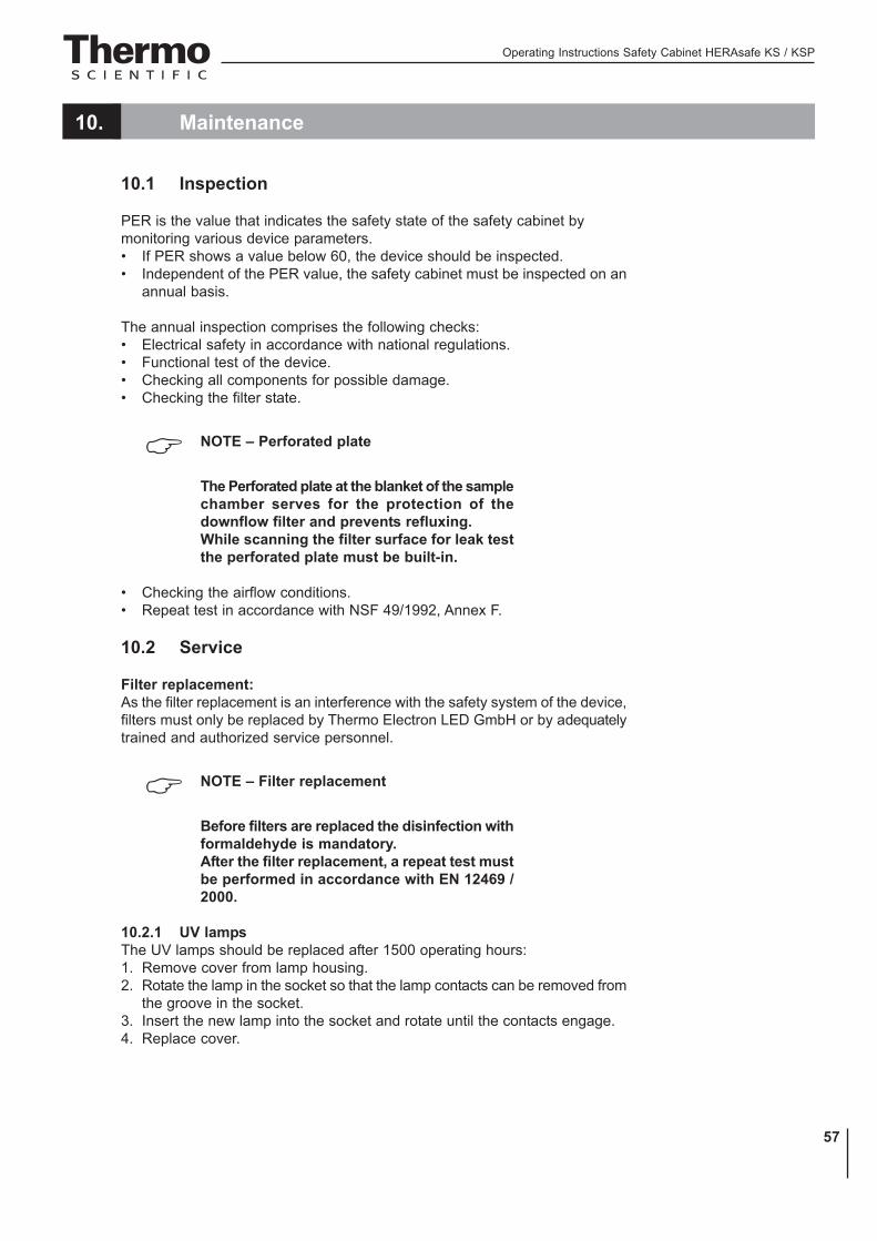
Operating Instructions Safety Cabinet HERAsafe KS / KSP
57
10. Maintenance
10.1 Inspection
PER is the value that indicates the safety state of the safety cabinet bymonitoring various device parameters.• If PER shows a value below 60, the device should be inspected.• Independent of the PER value, the safety cabinet must be inspected on an
annual basis.
The annual inspection comprises the following checks:• Electrical safety in accordance with national regulations.• Functional test of the device.• Checking all components for possible damage.• Checking the filter state.
NOTE – Perforated plate
The Perforated plate at the blanket of the samplechamber serves for the protection of thedownflow filter and prevents refluxing.While scanning the filter surface for leak testthe perforated plate must be built-in.
• Checking the airflow conditions.• Repeat test in accordance with NSF 49/1992, Annex F.
10.2 Service
Filter replacement:As the filter replacement is an interference with the safety system of the device,filters must only be replaced by Thermo Electron LED GmbH or by adequatelytrained and authorized service personnel.
NOTE – Filter replacement
Before filters are replaced the disinfection withformaldehyde is mandatory.After the filter replacement, a repeat test mustbe performed in accordance with EN 12469 /2000.
10.2.1 UV lampsThe UV lamps should be replaced after 1500 operating hours:1. Remove cover from lamp housing.2. Rotate the lamp in the socket so that the lamp contacts can be removed from
the groove in the socket.3. Insert the new lamp into the socket and rotate until the contacts engage.4. Replace cover.

Operating Instructions Safety Cabinet HERAsafe KS / KSP
58
10. Maintenance
10.2.2 Sample chamber illuminationThe tubes are installed in the front cover bezel.1. Remove the bezel retaining screws and the bezel.2. The luminescent tubes are retained by rotatable sockets. Rotate the tube
carefully to the removal position and remove it from the socket.3. Insert the replacement tube and rotate it to the working position.4. Reinstall the bezel and secure it with the screws.
10.2.3 Replacing the front window sealFig. 18: When the front window seal shows visible sign of wear, the seal mustbe replaced.The sealing is slipped onto the housing frame and secured by an additionalretaining strip at the lower edge of the sample chamber opening.
1. Lower the front window completely and open the front cover.2. Remove the retaining screws [3] and remove the retaining strip [2].3. Remove the seal [1] from the housing frame retaining lip.4. Slip the groove of the new seal onto the housing frame retaining lip and push
it on so that the seal fits evenly along the entire sealing surface.5. Secure the retaining strip with the screws.
Fig. 18Front window seal replacement

Operating Instructions Safety Cabinet HERAsafe KS / KSP
59
10. Maintenance
10.3 Retrofitting and repairs
External communication systems, e.g. failure report systems or components forsupplying media such as gas solenoid valves can be retrofitted and integratedinto the device control.
NOTE – Retrofitting and repairs
All retrofitting and repair work are interferenceswith the safety system of the unit. Particularlymodifications to the filter system and resultingchanges of the airflow may impair personal andmaterial protection. Such work must be carriedout only by authorized service personnel.
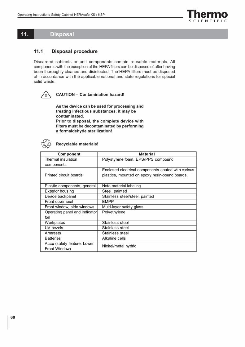
Operating Instructions Safety Cabinet HERAsafe KS / KSP
60
11. Disposal
11.1 Disposal procedure
Discarded cabinets or unit components contain reusable materials. Allcomponents with the exception of the HEPA filters can be disposed of after havingbeen thoroughly cleaned and disinfected. The HEPA filters must be disposedof in accordance with the applicable national and state regulations for specialsolid waste.
CAUTION – Contamination hazard!
As the device can be used for processing andtreating infectious substances, it may becontaminated.Prior to disposal, the complete device withfilters must be decontaminated by performinga formaldehyde sterilization!
Recyclable materials!
Component MaterialThermal insulation components
Polystyrene foam, EPS/PPS compound
Printed circuit boardsEnclosed electrical components coated with various plastics, mounted on epoxy resin-bound boards.
Plastic components, general Note material labelingExterior housing Steel, paintedDevice backpanel Stainless steel/steel, paintedFront cover seal EMPPFront window, side windows Multi-layer safety glassOperating panel and indicator foil
Polyethylene
Workplates Stainless steelUV bezels Stainless steelArmrests Stainless steelBatteries Alkaline cellsAccu (safety feature: Lower Front Window)
Nickel/metal hydrid

Operating Instructions Safety Cabinet HERAsafe KS / KSP
61
11. Disposal
WEEE Compliance:
This product is required to comply with the European Union‘s Waste Electricaland Electronic Equipment (WEEE) Directive 2002/96/EC. It is marked with thefollowing symbol:
Thermo Fisher Scientific has contracted with one or more recycling/disposalcompanies in each EU Member State, and this product should be disposedof or recycled through them.Further information on Thermo Fisher Scientific‘s compliance with theseDirectives, the recyclers in your country, and information on Thermoproducts wich may assist the detection of substances subject to the RoHSDirective are available at www.thermo.com/WEEERoHS.

Operating Instructions Safety Cabinet HERAsafe KS / KSP
62
12. Technical data

Operating Instructions Safety Cabinet HERAsafe KS / KSP
63
12. Technical data
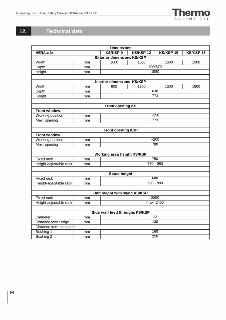
Operating Instructions Safety Cabinet HERAsafe KS / KSP
64
12. Technical data
KS/KSP 9 KS/KSP 12 KS/KSP 15 KS/KSP 18
Width mm 1000 1300 1600 1900Depth mmHeight mm
Width mm 900 1200 1500 1800Depth mmHeight mm
Working position mmMax. opening mm
Working position mmMax. opening mm
Fixed rack mmHeight-adjustable rack mm
Fixed rack mmHeight-adjustable rack mm
Fixed rack mmHeight-adjustable rack mm
Diameter mmDistance lower edge mm
Bushing 1 mmBushing 2 mm
Dimensions
Exterior dimensions KS/KSP
Interior dimensions KS/KSP
HERAsafe
800/8701580
630773
Front opening KSFront window
780
~250773
Distance from backpanel
250
Front opening KSPFront window
~200
130
160
23Side wall feed throughs KS/KSP
max. 2460
750 - 950
2260
Working area height KS/KSP
Stand height
680 - 880
Unit height with stand KS/KSP
680
750
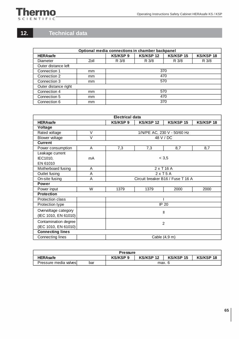
Operating Instructions Safety Cabinet HERAsafe KS / KSP
65
12. Technical data
KS/KSP 9 KS/KSP 12 KS/KSP 15 KS/KSP 18Diameter Zoll R 3/8 R 3/8 R 3/8 R 3/8
Connection 1 mmConnection 2 mmConnection 3 mm
Connection 4 mmConnection 5 mmConnection 6 mm
KS/KSP 9 KS/KSP 12 KS/KSP 15 KS/KSP 18
Rated voltage VBlower voltage V
Power consumption A 7,3 7,3 8,7 8,7Leakage current IEC1010, EN 61010
mA
Motherboard fusing AOutlet fusing AOn-site fusing A
Power input W 1379 1379 2000 2000
Protection classProtection type
Overvoltage category(IEC 1010, EN 61010)
Contamination degree (IEC 1010, EN 61010)
Connecting lines
KS/KSP 9 KS/KSP 12 KS/KSP 15 KS/KSP 18Pressure media valves barHERAsafe
max. 6
II
2
Connecting linesCable (4,9 m)
ProtectionI
IP 20
Pressure
2 x T 16 A2 x T 5 A
Circuit breaker B16 / Fuse T 16 APower
1/N/PE AC, 230 V - 50/60 Hz48 V / DC
Current
< 3,5
HERAsafe
470370
Voltage
570
Outer distance left370
Electrical data
Optional media connections in chamber backpanel
470
HERAsafe
Outer distance right570
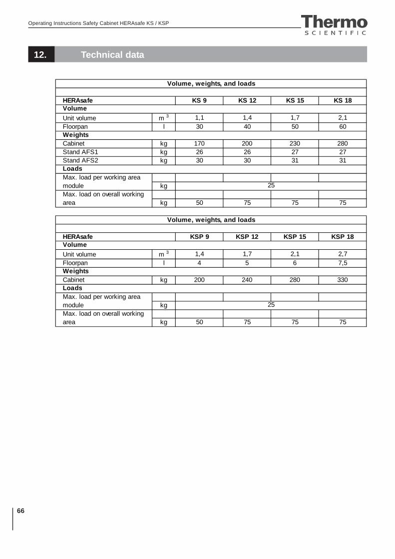
Operating Instructions Safety Cabinet HERAsafe KS / KSP
66
12. Technical data
HERAsafe KS 9 KS 12 KS 15 KS 18
Unit volume m 3 1,1 1,4 1,7 2,1Floorpan l 30 40 50 60
Cabinet kg 170 200 230 280Stand AFS1 kg 26 26 27 27Stand AFS2 kg 30 30 31 31
kg
kg 50 75 75 75
KSP 9 KSP 12 KSP 15 KSP 18
Unit volume m 3 1,4 1,7 2,1 2,7Floorpan l 4 5 6 7,5
Cabinet kg 200 240 280 330
kg
kg 50 75 75 75
25
25
Volume
Weights
Loads
Max. load on overall working area
Max. load per working area module
Volume, weights, and loads
Volume, weights, and loads
HERAsafeVolume
Max. load on overall working area
Weights
LoadsMax. load per working area module
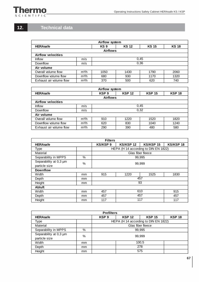
Operating Instructions Safety Cabinet HERAsafe KS / KSP
67
12. Technical data
KS 9 KS 12 KS 15 KS 18
Inflow m/sDownflow m/s
Overall volume flow m³/h 1050 1430 1790 2060Downflow volume flow m³/h 680 930 1170 1320Exhaust air volume flow m³/h 370 500 620 740
HERAsafe KSP 9 KSP 12 KSP 15 KSP 18
Inflow m/sDownflow m/s
Overall volume flow m³/h 910 1220 1520 1820Downflow volume flow m³/h 620 830 1040 1240Exhaust air volume flow m³/h 290 390 480 580
KS/KSP 9 KS/KSP 12 KS/KSP 15 KS/KSP 18TypeMaterialSeparability in MPPS %
Width mm 915 1220 1525 1830Depth mmHeight mm
Width mm 457 915Depth mm 457 457Height mm 117 117
KSP 9 KSP 12 KSP 15 KSP 18TypeMaterialSeparability in MPPS %
Width mmDepth mmHeight mm
457
117
Airflow velocities0,450,32
575
Air volume
Prefilters
100,5278
610457
HERAsafeHEPA (H 14 according to DIN EN 1822)
Glas fiber fleece
HERAsafe
Abluft
Downflow
Separability at 0,3 µm particle size
99,999%
99,995
Airflow system
Airflows
93
Airflow system
Airflows
Glas fiber fleece
Air volume
HEPA (H 14 according to DIN EN 1822)
Filters
Airflow velocities
HERAsafe
0,360,45
99,995Separability at 0,3 µm particle size
% 99,999
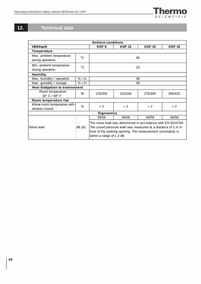
Operating Instructions Safety Cabinet HERAsafe KS / KSP
68
12. Technical data
KSP 9 KSP 12 KSP 15 KSP 18
Max. ambient temperature during operation
°C
Min. ambient temperature during operation
°C
Max. humidity / operation % r.H.Max. gumidity / storage % r.H.
58/56 58/56 60/58 60/58
The noise level was determined in accordance with EN ISO3744. The sound pressure level was measured at a distance of 1 m in front of the working opening. The measurement uncertainty is within a range of ± 2 dB.
Room temperature rise
W 170/200 210/240 275/305 350/420
< 2Above room temperature with window closed
Ambient conditions
9590
Humidity
40
10
HERAsafe
Noise level dB (A)
Room temperature 20° C / 68° F
Temperature
Heat dissipation to environment
°K < 2 < 2 < 2
Ergonomics
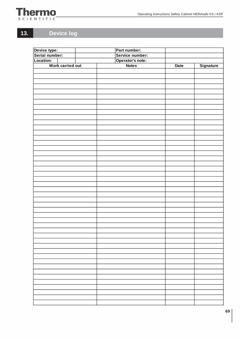
Operating Instructions Safety Cabinet HERAsafe KS / KSP
69
13. Device log
Part number:Serial number: Service number:Location: Operator's note:
Date Signature
Device type:
Work carried out Notes
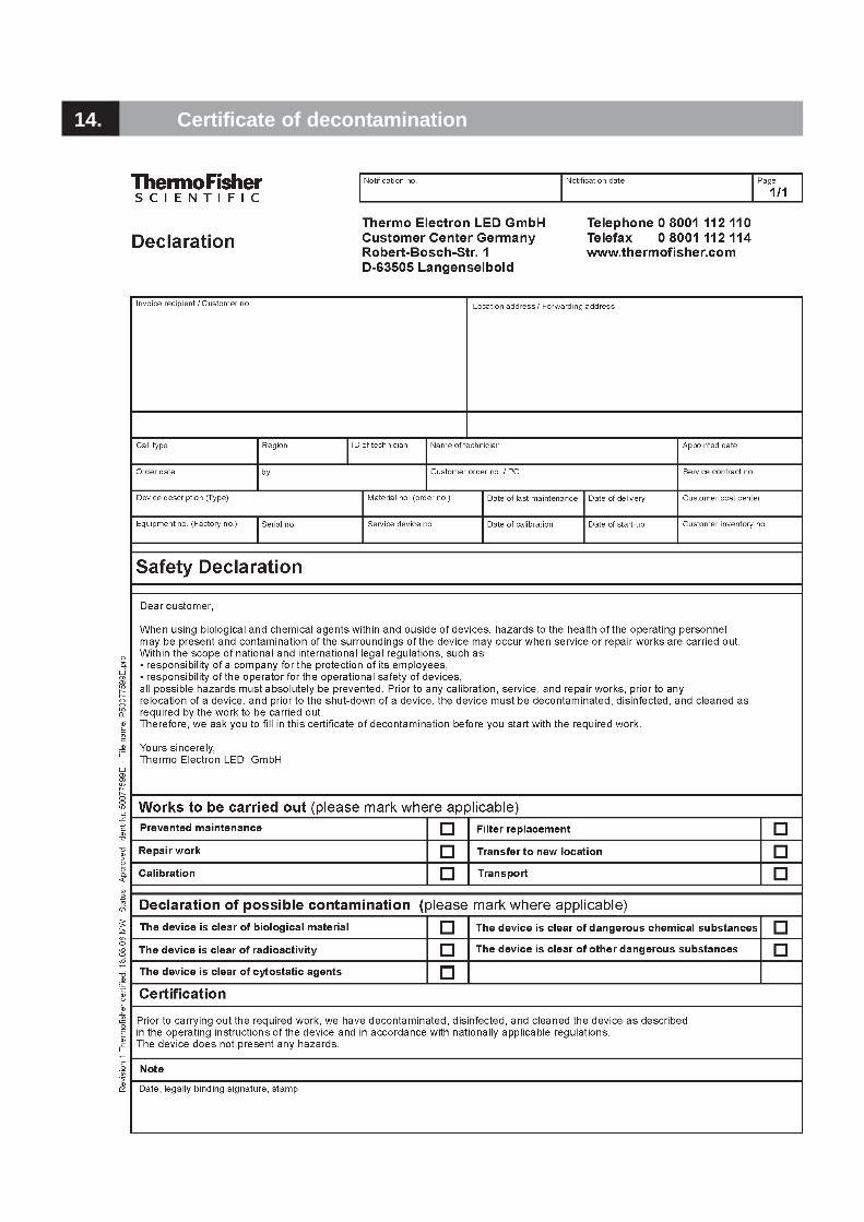
14. Certificate of decontamination

Operating Instructions Safety Cabinet HERAsafe KS / KSP
71
Internet: http://www.thermo.com