Embed Size (px)
Citation preview

HEPTI RRC “Kurchatov Institute”
HYDROGEN SAFETY ASPECTS RELATED TOHIGH PRESSURE PEM WATER ELECTROLYSIS
Fateev V.N.1, Grigoriev S.A.1, Millet P.2, Korobtsev S.V.1,Porembskiy V.I.1, Pepic M.3, Etievant C.4, Puyenchet C.4
1 Hydrogen Energy and Plasma Technology Institute of Russian Research Center “Kurchatov Institute”, Kurchatov sq. 1, Moscow, 123182, Russia, [email protected]
2 Institut de Chimie Moléculaire et des Matériaux, UMR CNRS n° 8182, Université Paris Sud,bât 420, 91405 Orsay Cedex France
3 DELTA PLUS Engineering & Consulting, Liege Science Park, Avenue Pré-Aily 1,B-4031, Angleur-Liège, Belgium
4 Compagnie Européenne des Technologies de l’Hydrogène, route de Nozay,Etablissements Alcatel, 91460 Marcoussis cedex France

Cwac,CHac
Cwcg, CNcg, COcg
Cwc, CNc, CO
Cwa, CHa
Cwm
NOсc Nwc
c
NHa
ca Nwa
c
Nwm
Nwa, NHa
Nwa, NOa NNc
x
y
z
h
hc
hm
hg
h
a 2b
a 2b
РНЦ«Курчатовский
Институт»
HYDROGEN ENERGY & PLASMA TECHNOLOGY INSTITUTE
HEPTI RRC “Kurchatov Institute”
Stoichiometric ratio of anode flow, rel.
2 4 6 8 10 12
Sto
ich
iom
etr
ic r
atio
of
cath
od
e f
low , re
l.
2
3
4
5
6

ABSTRACT
Polymer electrolyte membrane (PEM) water electrolysis has demonstrated its potentialities in terms of cell efficiency (energy consumption 4.0-4.2 kW/Nm3 H2) and gas purity (> 99.99% H2). Current research activities are aimed at increasing operating pressure up to several hundred bars for direct storage of hydrogen in pressurized vessels. Compared to atmospheric pressure electrolysis, high-pressure operation yields additional problems, especially with regard to safety considerations. In particular the rate of gases (H2 and O2) cross-permeation across the membrane and their water solubility both increase with pressure. As a result, gas purity is affected in both anodic and cathodic circuits, and this can lead to the formation of explosive gas mixtures. To prevent such risks, two different solutions, reported in this communication, have been investigated. First, the chemical modification of the solid polymer electrolyte, in order to reduce cross-permeation phenomena. Second, the use of catalytic H2/O2 recombiners to maintain H2 levels in O2 and O2 levels in H2 at values compatible with safety requirements.

Cell voltage (U), power (W) and energy efficiency dependence on current density for modern and developing electrolyzers
Cell voltage (U), power (W) and energy efficiency dependence on current density for modern and developing electrolyzers
1 – industrial alkali electrolyzers and its modern modifications (70-95 С);2 – electrolyzers for electrolysis in alkali melt (330-400 С; 0,1-1,0 MPa);3 – solid polymer (PEM) electrolyzers (90-110С; 0,1-3,0 MPa);4 – high temperature electrolyzers (900С; 0,1 MPa).
Energy losses of power sources of electrolyzers and heat losses were not taken into account
3

INTRODUCTION
Polymer electrolyte membrane (PEM) water electrolysiss, is currently the subject of extensive studies. PEM technology provides an example of “zero-gap” configuration, in which electrodes (nano-sized electrocatalyst particles supported by a porous electronic conductor) are in direct contact with the surface of the ion exchange membrane. This cell concept offers some significant advantages compared to traditional electrolyzers with liquid electrolyte and not zero-gap design: (i) pure water being the only reactant provides high gas purity; (ii) low voltage losses in electrolyte and possibility to operate at high current density, (iii) low membrane gas permeability gives possibility for safe operation at high pressure. As a result, low energy consumption (4.0-4.2 kW/Nm3 H2), high specific productivity (current densities up to 2 A/cm2), high hydrogen purity (>99.99%) and possibility to operate at 30-50 bars are realized. High-pressure (up to several hundred bars) electrolysers are currently needed for direct storage of hydrogen in pressurized vessels. Such electrolyzers would be of particular interest for small-scale (5-50 kW) energy systems powered by renewable energy sources, hydrogen filling stations and so on. But operation at high pressure results in increases the level of cross-contamination, decrease of current efficiency, gas purity and can lead to the formation of explosive H2/O2 gas mixtures, either in the electrolyser itself or in the liquid-gas separators. Two different strategies are used in present research to avoid these problems (i) reduction of hydrogen cross-permeation; (ii) reduction of hydrogen contents in the oxygen-water output stream of anodic cells.Results reported in this communication were obtained mainly during the GenHyPEM STREP project, financially supported by the European Commission in the course of the 6th Framework Research Program.

Water electrolysis cell with PEM
Overall reaction: H2O 1/2O2 + H2
Current collector
Bipolar plate
ANODE ZONE
Proton exchange membraneElectrocatalytic layer
O2
CATHODE ZONE
H2
Н2О
O2 + Н2ОH2
Н2О
H2O 2H+ + 1/2O2 + 2e–
2H+ H2 – 2e–
Н+nH2O
+-
Н2О Н2О
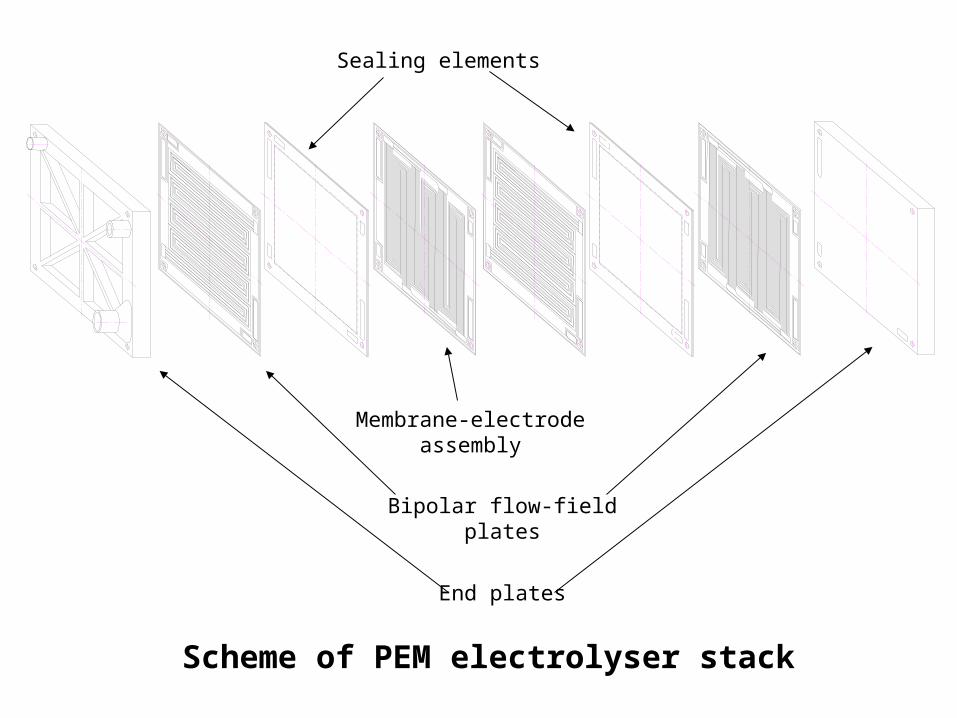
Scheme of PEM electrolyser stack
Membrane-electrode assembly
Sealing elements
Bipolar flow-field plates
End plates

PEM electrolysers for high purity hydrogen production with productivity up to 2 m3/hour and operating pressure up to 30 bars
Performances of PEM water electrolysers
- Power consumption 4.0-4.2 kW*hour/m3 of H2
- Voltage on the cell 1.67-1.72 V at i=1 A/cm2 and t=90C- Operating pressure up to 30 bars and more- Hydrogen purity > 99.99%- Noble metal content in catalytic layer: anode 1.0-2.0 mg/cm2
cathode 0.5-1.0 mg/cm2
- Life time (average) > 20000 hours
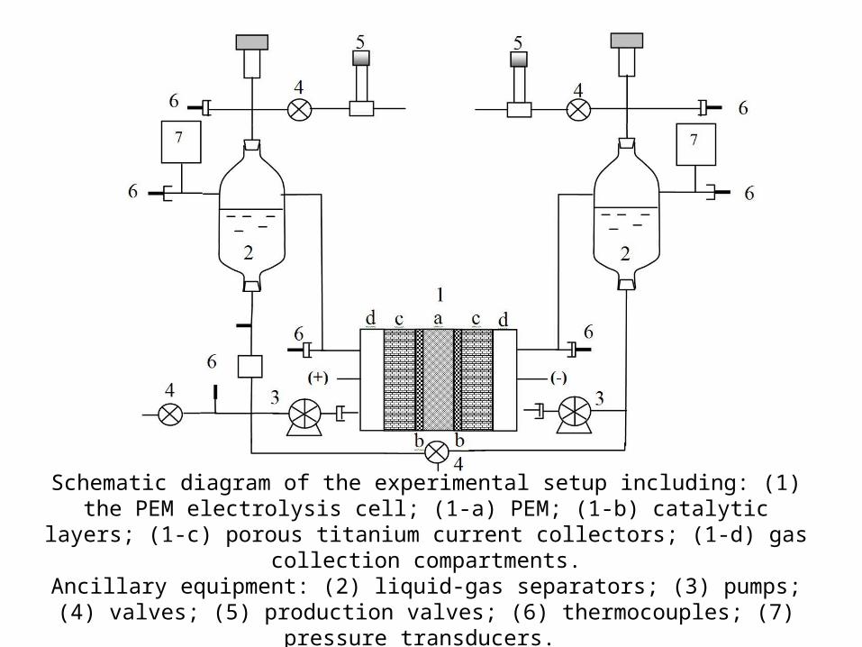
Schematic diagram of the experimental setup including: (1) the PEM electrolysis cell; (1-a) PEM; (1-b) catalytic layers; (1-c) porous titanium current collectors; (1-d) gas
collection compartments.Ancillary equipment: (2) liquid-gas separators; (3) pumps; (4) valves; (5) production
valves; (6) thermocouples; (7) pressure transducers.

Lab-scale polarization curves measured during PEM water electrolysis at T = 90C and different operating pressures:
1 – P = 1 bar; 2 – P = 50 bar.
E=E0 + RT/nF ln(PН2 РО21/2)
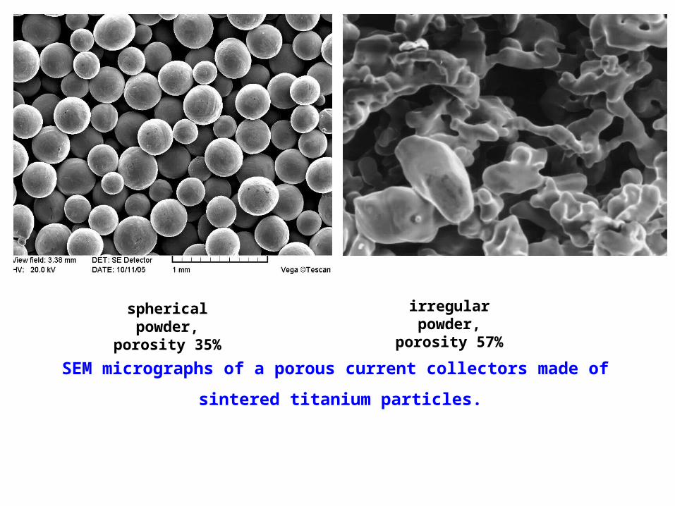
spherical powder, porosity 35%
SEM micrographs of a porous current collectors made of
sintered titanium particles.
irregular powder, porosity 57%

Lab-scale measurements of anodic and cathodic cell current efficiencies as a function of current density at 2 and 30 bar

Hydrogen content (vol.%) in the anodic oxygen-water vapour mixture, measured at 1, 6 and 30 bar in the liquid-gas separator as a function of operating current density.
50 cm2 monocell. Pt as cathodic catalyst, Ir as anodic catalyst and Nafion®-117 as PEM.

200
100
60
30
Hydrogen detector Catalytic hydrogen recombiner

The photograph of the experimental stand for
measuring HPCM characteristics.
Flow rate G, m3/min.
Pre
ssur
e d
rop dP
, mm
. wat
er c
olu
mn
0
0,2
0,4
0,6
0,8
1,0
1,2
1,4
0,1 0,2 0,3 0,4 0,5 0,6 0,7 0,8
dP=1,064G^1,465
dP=1,374G^1,519
dP=1,581G^1,526
dP=1,680G^1,517
dP=1,742G^1,780
dP=1,917G^1,578
Dependences of pressure drop for various HPCM samples (1 x 10 x 15 cm) of gas flow rate.
Maximal productivity of recombiner 100 m3/h (for 4 vol. % of H2)

CONCLUSIONS
PEM water electrolysers, operating at pressures up to 70 bar, can be used to produce hydrogen and oxygen of electrolytic grade suitable for PEM fuel cells, with high efficiencies. However, because of increasing rate of gas cross-permeation with pressure, the concentration of hydrogen in oxygen and the concentration of hydrogen in oxygen can reach critical levels. To avoid the formation of explosive gas mixtures, it is necessary to reduce gas cross-permeation. This can be done to a certain extend by surface modifying the solid electrolyte, for example by coating low-permeability protective layers and introduction inside the membrane inorganic proton conducting compounds. Contaminant concentration in the produced gases can also be reduced by adding catalytic gas recombiners, directly in the electrolysis cell or along the production line (gas separators). By using gas recombiners inside the electrolysis cell, it was possible to maintain hydrogen contents below 2 vol.% at large interval of current density at an operating pressure of 30 bar, with Nafion® 117 as solid electrolyte.