Embed Size (px)
Citation preview
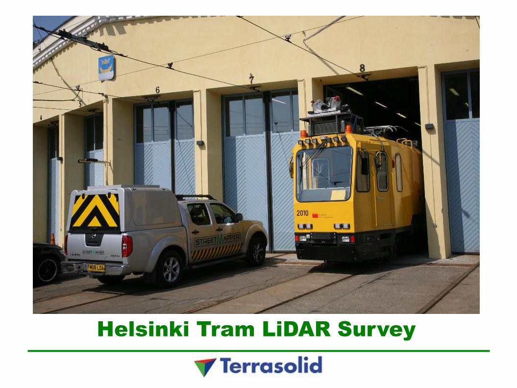
Helsinki Tram LiDAR Survey


Terrasolid Ltd.
Privately held company based in Finland
Founded in 1989, 12 employees
Last fiscal year revenues 4,5 M€
23+ years of software development on MicroStation and other Bentley applications
15+ years of point cloud software development
Over 4000 TerraScan licenses sold in over 90 countries
Global market leader in airborne and mobile laser scanned point cloud processing with an estimated 85% market share

Terrasolid products for LiDAR
TerraScan – Classify and handle point clouds
TerraMatch – Match multiple flight / drive passes
TerraPhoto – True ortho production and texturing
TerraModeler – DTM and contour production
TerraSurvey – Field control measurements

Helsinki Tram Network
About 200 000 passengers per day
Lines 1, 1A, 3T, 3B, 4, 4T, 6, 7A, 7B, 8, 9, 10
85 kilometers of commuter track
97 kilometers of track in total
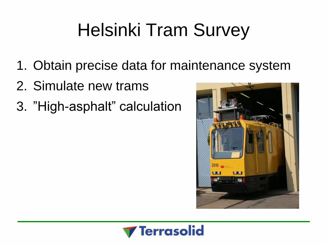
Helsinki Tram Survey
1. Obtain precise data for maintenance system
2. Simulate new trams
3. ”High-asphalt” calculation

Data Collection
Carried out by 3D Laser Mapping
StreetMapper mounted on a tram
2 * 200 000 Hz scanner
Forward looking 2144 * 1424 camera
Tram installation 29th May 2011
Data collection drives 29th - 31st May 2011
Some images collected with system mounted on a car 1st June 2011

Data Collection
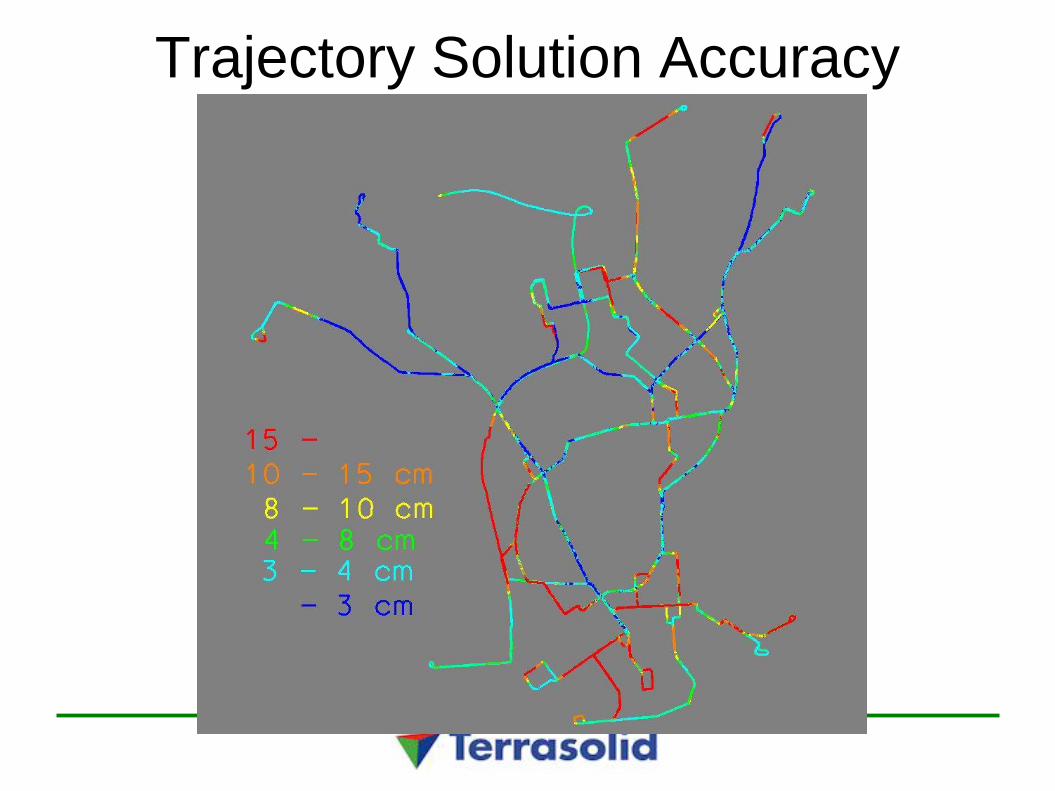
Trajectory Solution Accuracy

Data Volume
14 603 216 184 laser points collected
462 GB as .las files
19 628 forward looking images recorded
15 GB as .jpg images

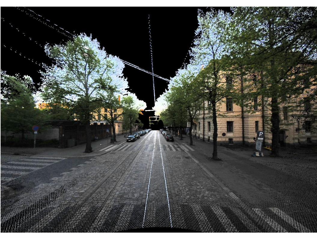
Forward Looking Images


Airborne Positioning
Fairly uniform satellite visibility
Fairly uniform positional accuracy
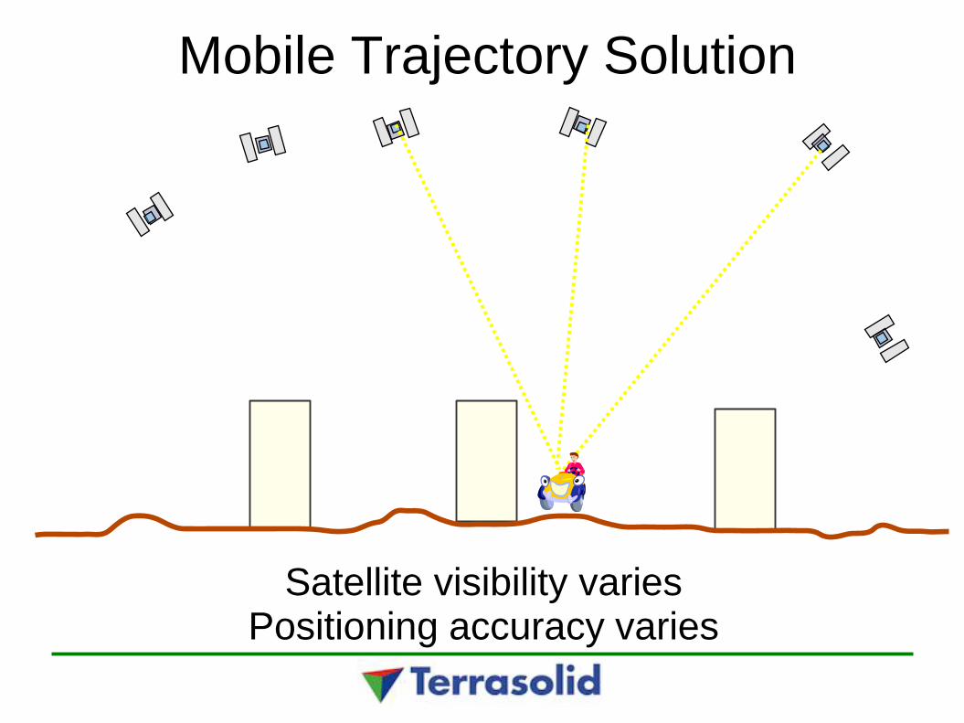
Mobile Trajectory Solution
Satellite visibility varies Positioning accuracy varies
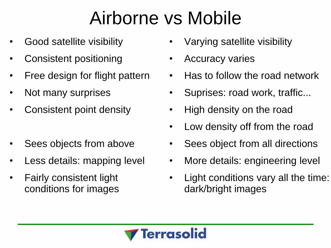
Airborne vs Mobile • Good satellite visibility
• Consistent positioning
• Free design for flight pattern
• Not many surprises
• Consistent point density
• Sees objects from above
• Less details: mapping level
• Fairly consistent light conditions for images
• Varying satellite visibility
• Accuracy varies
• Has to follow the road network
• Suprises: road work, traffic...
• High density on the road
• Low density off from the road
• Sees object from all directions
• More details: engineering level
• Light conditions vary all the time: dark/bright images

Combine airborne and mobile
With airborne LiDAR you'll get more precise Z- and positional accuracy
With airborne you'll see the building roofs → automatically vectorized buildings
Use oblique images to texture building walls
With mobile much more detail and relative precision
Use both for maximum accuracy and detail

Automatic Search for Signal Markers • Automatic search for known pattern control points
• Software finds location (and rotation) with biggest intensity difference between bright and dark polygons
• Rotation can be fixed or come from closest trajectory travel direction

How to Define a Signal Marker
• Draw signal pattern in a top view window
• Draw polygons for bright areas
• Draw larger polygon for dark surrounding
• Settings tool and Signal markers category
• Select all polygons
• Select Add
• Click at location of the control point

Fluctuating Corrections Xy correction vectors for drive pass in difficult
city environment

Automatic rail detection
• Define rail section template
• Detect rails

Geometry Component Fitting
● Finds design geometry built from lines, arcs and clothoids which best match surveyed alignment of a road or a railroad
● Fitting for both horizontal and vertical geometry
● Goals:
● View current geometry of road/railroad/pipeline in design software such as Bentley InRoads, Bentley Track etc passing geometry as LandXML file or similar
● Is curvature right for this category of road?
● Do component changes follow design principles?
● Find long span deformations

Source Information
● Components are fitted to a design file vector
● Vector can be created as a result of:
● Automatic/manual placement of 3D road centerline based on an airborne or a mobile LiDAR+camera survey
● Fitting railroad cross section to mobile LiDAR surveys of track
● Trajectory solution of survey vehicle

Horizontal Geometry
Exaggerated difference
Surveyed alignment
Fitted components Fitted components and differences to survey
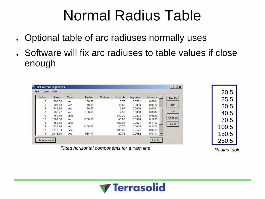
Normal Radius Table
● Optional table of arc radiuses normally uses
● Software will fix arc radiuses to table values if close enough
Fitted horizontal components for a tram line
20.5 25.5 30.5 40.5 70.5
100.5 150.5 250.5
Radius table

Vertical Geometry
Fitted vertical components for a tram line
Fitted vertical components as a profile