Embed Size (px)
Citation preview

en
USER’S GUIDEHelO2
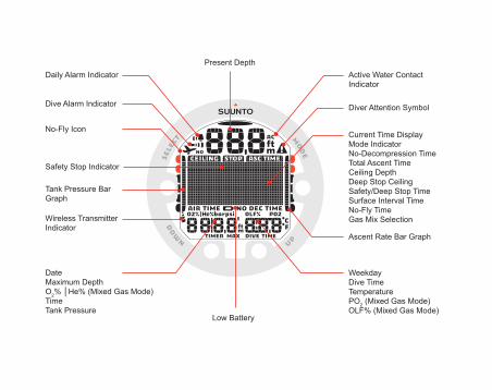
Daily Alarm Indicator
Dive Alarm Indicator
No-Fly Icon
Safety Stop Indicator
Tank Pressure Bar Graph
DateMaximum DepthO2% │He% (Mixed Gas Mode)TimeTank Pressure
Present Depth
Low Battery
Active Water Contact Indicator
Diver Attention Symbol
Current Time DisplayMode IndicatorNo-Decompression TimeTotal Ascent TimeCeiling DepthDeep Stop CeilingSafety/Deep Stop TimeSurface Interval TimeNo-Fly TimeGas Mix Selection
Ascent Rate Bar Graph
WeekdayDive TimeTemperaturePO2 (Mixed Gas Mode)OLF% (Mixed Gas Mode)
Wireless Transmitter Indicator
1. WELCOME TO THE WORLD OF SUUNTO DIVE COMPUTERS ... . . . . . . . . . . . . . . 81.1. Using HelO2 with Dive Manager and Dive Planner . . . . . . . . . . . . . . . . . . . . . . . . . . . . 9
2. WARNINGS, CAUTIONS, AND NOTES ... . . . . . . . . . . . . . . . . . . . . . . . . . . . . . . . . . . . . . . . . . 103. SUUNTO HelO2 USER INTERFACE ... . . . . . . . . . . . . . . . . . . . . . . . . . . . . . . . . . . . . . . . . . . . . . 19
3.1. Navigating in the menus .. . . . . . . . . . . . . . . . . . . . . . . . . . . . . . . . . . . . . . . . . . . . . . . . . . . . . . . . 193.2. Button symbols and functions .. . . . . . . . . . . . . . . . . . . . . . . . . . . . . . . . . . . . . . . . . . . . . . . . . . 20
4. GETTING STARTED ... . . . . . . . . . . . . . . . . . . . . . . . . . . . . . . . . . . . . . . . . . . . . . . . . . . . . . . . . . . . . . . . 224.1. TIME mode settings .. . . . . . . . . . . . . . . . . . . . . . . . . . . . . . . . . . . . . . . . . . . . . . . . . . . . . . . . . . . . . 22
4.1.1. Setting the time .. . . . . . . . . . . . . . . . . . . . . . . . . . . . . . . . . . . . . . . . . . . . . . . . . . . . . . . . . . . . . 234.1.2. Setting the date .. . . . . . . . . . . . . . . . . . . . . . . . . . . . . . . . . . . . . . . . . . . . . . . . . . . . . . . . . . . . . 234.1.3. Setting the units . . . . . . . . . . . . . . . . . . . . . . . . . . . . . . . . . . . . . . . . . . . . . . . . . . . . . . . . . . . . . 244.1.4. Setting the backlight . . . . . . . . . . . . . . . . . . . . . . . . . . . . . . . . . . . . . . . . . . . . . . . . . . . . . . . . 244.1.5. Setting the tones .. . . . . . . . . . . . . . . . . . . . . . . . . . . . . . . . . . . . . . . . . . . . . . . . . . . . . . . . . . . 24
4.2. AC water contacts . . . . . . . . . . . . . . . . . . . . . . . . . . . . . . . . . . . . . . . . . . . . . . . . . . . . . . . . . . . . . . . . 255. BEFORE DIVING ... . . . . . . . . . . . . . . . . . . . . . . . . . . . . . . . . . . . . . . . . . . . . . . . . . . . . . . . . . . . . . . . . . . . 27
5.1. Planning your dives .. . . . . . . . . . . . . . . . . . . . . . . . . . . . . . . . . . . . . . . . . . . . . . . . . . . . . . . . . . . . . 285.2. The Suunto Technical RGBM ... . . . . . . . . . . . . . . . . . . . . . . . . . . . . . . . . . . . . . . . . . . . . . . . . 295.3. Emergency ascents . . . . . . . . . . . . . . . . . . . . . . . . . . . . . . . . . . . . . . . . . . . . . . . . . . . . . . . . . . . . . . 305.4. Dive computer limitations .. . . . . . . . . . . . . . . . . . . . . . . . . . . . . . . . . . . . . . . . . . . . . . . . . . . . . . . 315.5. Audible and visual alarms .. . . . . . . . . . . . . . . . . . . . . . . . . . . . . . . . . . . . . . . . . . . . . . . . . . . . . . 315.6. Error conditions .. . . . . . . . . . . . . . . . . . . . . . . . . . . . . . . . . . . . . . . . . . . . . . . . . . . . . . . . . . . . . . . . . . 345.7. Wireless transmission .. . . . . . . . . . . . . . . . . . . . . . . . . . . . . . . . . . . . . . . . . . . . . . . . . . . . . . . . . . . 36
5.7.1. Installing the wireless transmitter . . . . . . . . . . . . . . . . . . . . . . . . . . . . . . . . . . . . . . . . . . 365.7.2. Pairing and code selection .. . . . . . . . . . . . . . . . . . . . . . . . . . . . . . . . . . . . . . . . . . . . . . . . 37
3

5.7.3. Transmitting data .. . . . . . . . . . . . . . . . . . . . . . . . . . . . . . . . . . . . . . . . . . . . . . . . . . . . . . . . . . . 395.8. MIXED GAS DIVE mode settings .. . . . . . . . . . . . . . . . . . . . . . . . . . . . . . . . . . . . . . . . . . . . . . 41
5.8.1. Setting the gases .. . . . . . . . . . . . . . . . . . . . . . . . . . . . . . . . . . . . . . . . . . . . . . . . . . . . . . . . . . . 425.8.2. Setting the depth alarm .. . . . . . . . . . . . . . . . . . . . . . . . . . . . . . . . . . . . . . . . . . . . . . . . . . . . 435.8.3. Setting the dive-time alarm .. . . . . . . . . . . . . . . . . . . . . . . . . . . . . . . . . . . . . . . . . . . . . . . 445.8.4. Setting the personal/altitude adjustments . . . . . . . . . . . . . . . . . . . . . . . . . . . . . . . . 445.8.5. Setting the sample rate .. . . . . . . . . . . . . . . . . . . . . . . . . . . . . . . . . . . . . . . . . . . . . . . . . . . . 455.8.6. Setting the tank pressure alarm .. . . . . . . . . . . . . . . . . . . . . . . . . . . . . . . . . . . . . . . . . . 455.8.7. Setting the tank pressure .. . . . . . . . . . . . . . . . . . . . . . . . . . . . . . . . . . . . . . . . . . . . . . . . . . 465.8.8. Setting the HP code .. . . . . . . . . . . . . . . . . . . . . . . . . . . . . . . . . . . . . . . . . . . . . . . . . . . . . . . . 465.8.9. Setting the units . . . . . . . . . . . . . . . . . . . . . . . . . . . . . . . . . . . . . . . . . . . . . . . . . . . . . . . . . . . . . 47
5.9. Activation and pre-checks .. . . . . . . . . . . . . . . . . . . . . . . . . . . . . . . . . . . . . . . . . . . . . . . . . . . . . . 475.9.1. Accessing DIVE mode .. . . . . . . . . . . . . . . . . . . . . . . . . . . . . . . . . . . . . . . . . . . . . . . . . . . . . 485.9.2. DIVE mode activation .. . . . . . . . . . . . . . . . . . . . . . . . . . . . . . . . . . . . . . . . . . . . . . . . . . . . . . 485.9.3. Battery power indication .. . . . . . . . . . . . . . . . . . . . . . . . . . . . . . . . . . . . . . . . . . . . . . . . . . . 505.9.4. Diving at altitude .. . . . . . . . . . . . . . . . . . . . . . . . . . . . . . . . . . . . . . . . . . . . . . . . . . . . . . . . . . . . 515.9.5. Personal adjustments . . . . . . . . . . . . . . . . . . . . . . . . . . . . . . . . . . . . . . . . . . . . . . . . . . . . . . . 52
5.10. Safety Stops .. . . . . . . . . . . . . . . . . . . . . . . . . . . . . . . . . . . . . . . . . . . . . . . . . . . . . . . . . . . . . . . . . . . . 545.10.1. Recommended Safety Stops .. . . . . . . . . . . . . . . . . . . . . . . . . . . . . . . . . . . . . . . . . . . . 545.10.2. Mandatory Safety Stops .. . . . . . . . . . . . . . . . . . . . . . . . . . . . . . . . . . . . . . . . . . . . . . . . . 55
5.11. Deep stops .. . . . . . . . . . . . . . . . . . . . . . . . . . . . . . . . . . . . . . . . . . . . . . . . . . . . . . . . . . . . . . . . . . . . . . 576. DIVING ... . . . . . . . . . . . . . . . . . . . . . . . . . . . . . . . . . . . . . . . . . . . . . . . . . . . . . . . . . . . . . . . . . . . . . . . . . . . . . . . 58
6.1. Diving-related information .. . . . . . . . . . . . . . . . . . . . . . . . . . . . . . . . . . . . . . . . . . . . . . . . . . . . . . 586.1.1. Basic dive data .. . . . . . . . . . . . . . . . . . . . . . . . . . . . . . . . . . . . . . . . . . . . . . . . . . . . . . . . . . . . . 59
4
6.1.2. Bookmark .. . . . . . . . . . . . . . . . . . . . . . . . . . . . . . . . . . . . . . . . . . . . . . . . . . . . . . . . . . . . . . . . . . . 606.1.3. Ascent rate indicator . . . . . . . . . . . . . . . . . . . . . . . . . . . . . . . . . . . . . . . . . . . . . . . . . . . . . . . . 606.1.4. Safety Stops .. . . . . . . . . . . . . . . . . . . . . . . . . . . . . . . . . . . . . . . . . . . . . . . . . . . . . . . . . . . . . . . . 616.1.5. Decompression dives .. . . . . . . . . . . . . . . . . . . . . . . . . . . . . . . . . . . . . . . . . . . . . . . . . . . . . . 62
6.2. Diving in MIXED GAS mode .. . . . . . . . . . . . . . . . . . . . . . . . . . . . . . . . . . . . . . . . . . . . . . . . . . . 676.2.1. Before diving in the MIXED GAS mode .. . . . . . . . . . . . . . . . . . . . . . . . . . . . . . . . . 676.2.2. Oxygen and helium displays .. . . . . . . . . . . . . . . . . . . . . . . . . . . . . . . . . . . . . . . . . . . . . . 686.2.3. Oxygen limit fraction (OLF%) .. . . . . . . . . . . . . . . . . . . . . . . . . . . . . . . . . . . . . . . . . . . . . 706.2.4. Gas change and multiple breathing gas mixes .. . . . . . . . . . . . . . . . . . . . . . . . . 71
6.3. Diving in the GAUGE mode .. . . . . . . . . . . . . . . . . . . . . . . . . . . . . . . . . . . . . . . . . . . . . . . . . . . . 727. AFTER DIVING ... . . . . . . . . . . . . . . . . . . . . . . . . . . . . . . . . . . . . . . . . . . . . . . . . . . . . . . . . . . . . . . . . . . . . . . 74
7.1. Surface interval . . . . . . . . . . . . . . . . . . . . . . . . . . . . . . . . . . . . . . . . . . . . . . . . . . . . . . . . . . . . . . . . . . . 747.2. Dive numbering .. . . . . . . . . . . . . . . . . . . . . . . . . . . . . . . . . . . . . . . . . . . . . . . . . . . . . . . . . . . . . . . . . . 757.3. Repetitive dive planning .. . . . . . . . . . . . . . . . . . . . . . . . . . . . . . . . . . . . . . . . . . . . . . . . . . . . . . . . 767.4. Flying after diving .. . . . . . . . . . . . . . . . . . . . . . . . . . . . . . . . . . . . . . . . . . . . . . . . . . . . . . . . . . . . . . . . 767.5. PLAN mode .. . . . . . . . . . . . . . . . . . . . . . . . . . . . . . . . . . . . . . . . . . . . . . . . . . . . . . . . . . . . . . . . . . . . . . 78
7.5.1. DIVE PLANNING mode (PLAN NoDec) . . . . . . . . . . . . . . . . . . . . . . . . . . . . . . . . . . 787.6. MEMORY mode .. . . . . . . . . . . . . . . . . . . . . . . . . . . . . . . . . . . . . . . . . . . . . . . . . . . . . . . . . . . . . . . . . 80
7.6.1. Dive logbook (MEM Logbook) . . . . . . . . . . . . . . . . . . . . . . . . . . . . . . . . . . . . . . . . . . . . . 817.6.2. Dive history . . . . . . . . . . . . . . . . . . . . . . . . . . . . . . . . . . . . . . . . . . . . . . . . . . . . . . . . . . . . . . . . . . 83
7.7. Suunto Dive Planner (SDP) .. . . . . . . . . . . . . . . . . . . . . . . . . . . . . . . . . . . . . . . . . . . . . . . . . . . . 847.8. Suunto DM4 with Movescount . . . . . . . . . . . . . . . . . . . . . . . . . . . . . . . . . . . . . . . . . . . . . . . . . . 867.9. Movescount . . . . . . . . . . . . . . . . . . . . . . . . . . . . . . . . . . . . . . . . . . . . . . . . . . . . . . . . . . . . . . . . . . . . . . . 87
8. CARE AND MAINTENANCE OF MY SUUNTO DIVING COMPUTER ... . . . . . . . 88
5

9. BATTERY REPLACEMENT ... . . . . . . . . . . . . . . . . . . . . . . . . . . . . . . . . . . . . . . . . . . . . . . . . . . . . . . . . 919.1. Battery kit . . . . . . . . . . . . . . . . . . . . . . . . . . . . . . . . . . . . . . . . . . . . . . . . . . . . . . . . . . . . . . . . . . . . . . . . . . 919.2. Required tools . . . . . . . . . . . . . . . . . . . . . . . . . . . . . . . . . . . . . . . . . . . . . . . . . . . . . . . . . . . . . . . . . . . . . 919.3. Replacing the battery . . . . . . . . . . . . . . . . . . . . . . . . . . . . . . . . . . . . . . . . . . . . . . . . . . . . . . . . . . . . . 929.4. Wireless transmitter battery replacement . . . . . . . . . . . . . . . . . . . . . . . . . . . . . . . . . . . . . . 95
9.4.1. Transmitter battery kit . . . . . . . . . . . . . . . . . . . . . . . . . . . . . . . . . . . . . . . . . . . . . . . . . . . . . . . 959.4.2. Required tools . . . . . . . . . . . . . . . . . . . . . . . . . . . . . . . . . . . . . . . . . . . . . . . . . . . . . . . . . . . . . . . 969.4.3. Replacing the transmitter battery . . . . . . . . . . . . . . . . . . . . . . . . . . . . . . . . . . . . . . . . . . 96
10. TECHNICAL DATA ... . . . . . . . . . . . . . . . . . . . . . . . . . . . . . . . . . . . . . . . . . . . . . . . . . . . . . . . . . . . . . . . . 9810.1. Technical specifications .. . . . . . . . . . . . . . . . . . . . . . . . . . . . . . . . . . . . . . . . . . . . . . . . . . . . . . . 9810.2. RGBM ... . . . . . . . . . . . . . . . . . . . . . . . . . . . . . . . . . . . . . . . . . . . . . . . . . . . . . . . . . . . . . . . . . . . . . . . . 102
10.2.1. Suunto Technical RGBM decompression model . . . . . . . . . . . . . . . . . . . . . 10210.2.2. Diver safety and Suunto Technical RGBM model . . . . . . . . . . . . . . . . . . . . 10410.2.3. Altitude diving .. . . . . . . . . . . . . . . . . . . . . . . . . . . . . . . . . . . . . . . . . . . . . . . . . . . . . . . . . . . . 105
10.3. Oxygen exposure .. . . . . . . . . . . . . . . . . . . . . . . . . . . . . . . . . . . . . . . . . . . . . . . . . . . . . . . . . . . . 10511. INTELLECTUAL PROPERTY ... . . . . . . . . . . . . . . . . . . . . . . . . . . . . . . . . . . . . . . . . . . . . . . . . . . . 107
11.1. Trademark .. . . . . . . . . . . . . . . . . . . . . . . . . . . . . . . . . . . . . . . . . . . . . . . . . . . . . . . . . . . . . . . . . . . . . 10711.2. Copyright . . . . . . . . . . . . . . . . . . . . . . . . . . . . . . . . . . . . . . . . . . . . . . . . . . . . . . . . . . . . . . . . . . . . . . . . 10711.3. Patent notice .. . . . . . . . . . . . . . . . . . . . . . . . . . . . . . . . . . . . . . . . . . . . . . . . . . . . . . . . . . . . . . . . . . 107
12. DISCLAIMERS ... . . . . . . . . . . . . . . . . . . . . . . . . . . . . . . . . . . . . . . . . . . . . . . . . . . . . . . . . . . . . . . . . . . . 10812.1. CE .. . . . . . . . . . . . . . . . . . . . . . . . . . . . . . . . . . . . . . . . . . . . . . . . . . . . . . . . . . . . . . . . . . . . . . . . . . . . . . 10812.2. EN 13319 .. . . . . . . . . . . . . . . . . . . . . . . . . . . . . . . . . . . . . . . . . . . . . . . . . . . . . . . . . . . . . . . . . . . . . . 10812.3. EN 250 / FIOH ... . . . . . . . . . . . . . . . . . . . . . . . . . . . . . . . . . . . . . . . . . . . . . . . . . . . . . . . . . . . . . . 108
13. SUUNTO LIMITED WARRANTY ... . . . . . . . . . . . . . . . . . . . . . . . . . . . . . . . . . . . . . . . . . . . . . . 109
6

14. DISPOSAL OF THE DEVICE .. . . . . . . . . . . . . . . . . . . . . . . . . . . . . . . . . . . . . . . . . . . . . . . . . . . . . 111GLOSSARY ... . . . . . . . . . . . . . . . . . . . . . . . . . . . . . . . . . . . . . . . . . . . . . . . . . . . . . . . . . . . . . . . . . . . . . . . . . . . 112
7
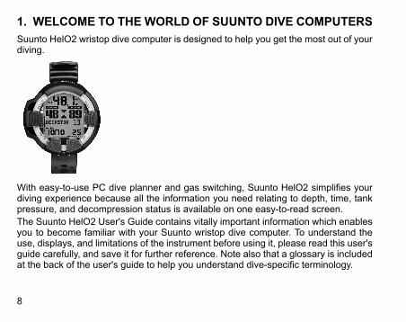
1. WELCOME TO THE WORLD OF SUUNTO DIVE COMPUTERSSuunto HelO2 wristop dive computer is designed to help you get the most out of yourdiving.
With easy-to-use PC dive planner and gas switching, Suunto HelO2 simplifies yourdiving experience because all the information you need relating to depth, time, tankpressure, and decompression status is available on one easy-to-read screen.The Suunto HelO2 User's Guide contains vitally important information which enablesyou to become familiar with your Suunto wristop dive computer. To understand theuse, displays, and limitations of the instrument before using it, please read this user'sguide carefully, and save it for further reference. Note also that a glossary is includedat the back of the user's guide to help you understand dive-specific terminology.
8
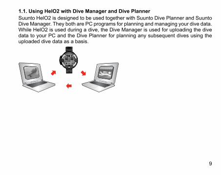
1.1. Using HelO2 with Dive Manager and Dive PlannerSuunto HelO2 is designed to be used together with Suunto Dive Planner and SuuntoDive Manager. They both are PC programs for planning and managing your dive data.While HelO2 is used during a dive, the Dive Manager is used for uploading the divedata to your PC and the Dive Planner for planning any subsequent dives using theuploaded dive data as a basis.
9
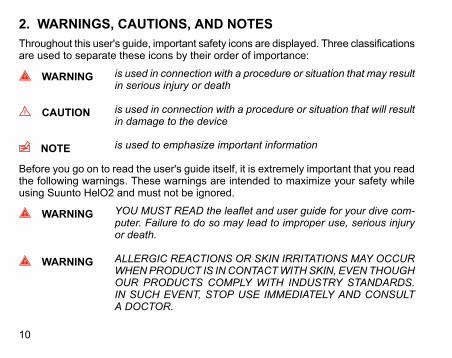
2. WARNINGS, CAUTIONS, AND NOTESThroughout this user's guide, important safety icons are displayed. Three classificationsare used to separate these icons by their order of importance:
WARNING is used in connection with a procedure or situation that may resultin serious injury or death
CAUTION is used in connection with a procedure or situation that will resultin damage to the device
NOTE is used to emphasize important information
Before you go on to read the user's guide itself, it is extremely important that you readthe following warnings. These warnings are intended to maximize your safety whileusing Suunto HelO2 and must not be ignored.
WARNING YOU MUST READ the leaflet and user guide for your dive com-puter. Failure to do so may lead to improper use, serious injuryor death.
WARNING ALLERGIC REACTIONS OR SKIN IRRITATIONS MAY OCCURWHENPRODUCT IS INCONTACTWITHSKIN, EVENTHOUGHOUR PRODUCTS COMPLY WITH INDUSTRY STANDARDS.IN SUCH EVENT, STOP USE IMMEDIATELY AND CONSULTA DOCTOR.
10
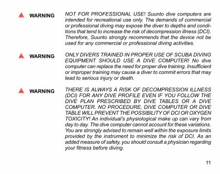
WARNING NOT FOR PROFESSIONAL USE! Suunto dive computers areintended for recreational use only. The demands of commercialor professional diving may expose the diver to depths and condi-tions that tend to increase the risk of decompression illness (DCI).Therefore, Suunto strongly recommends that the device not beused for any commercial or professional diving activities.
WARNING ONLY DIVERS TRAINED IN PROPER USE OF SCUBA DIVINGEQUIPMENT SHOULD USE A DIVE COMPUTER! No divecomputer can replace the need for proper dive training. Insufficientor improper training may cause a diver to commit errors that maylead to serious injury or death.
WARNING THERE IS ALWAYS A RISK OF DECOMPRESSION ILLNESS(DCI) FOR ANY DIVE PROFILE EVEN IF YOU FOLLOW THEDIVE PLAN PRESCRIBED BY DIVE TABLES OR A DIVECOMPUTER. NO PROCEDURE, DIVE COMPUTER OR DIVETABLEWILLPREVENTTHEPOSSIBILITYOFDCIOROXYGENTOXICITY! An individual’s physiological make up can vary fromday to day. The dive computer cannot account for these variations.You are strongly advised to remain well within the exposure limitsprovided by the instrument to minimize the risk of DCI. As anaddedmeasure of safety, you should consult a physician regardingyour fitness before diving.
11
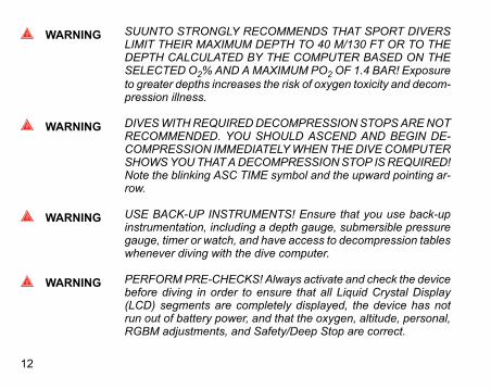
WARNING SUUNTO STRONGLY RECOMMENDS THAT SPORT DIVERSLIMIT THEIR MAXIMUM DEPTH TO 40 M/130 FT OR TO THEDEPTH CALCULATED BY THE COMPUTER BASED ON THESELECTED O2%AND AMAXIMUM PO2OF 1.4 BAR! Exposureto greater depths increases the risk of oxygen toxicity and decom-pression illness.
WARNING DIVESWITHREQUIREDDECOMPRESSIONSTOPSARENOTRECOMMENDED. YOU SHOULD ASCEND AND BEGIN DE-COMPRESSION IMMEDIATELYWHENTHEDIVECOMPUTERSHOWSYOUTHATADECOMPRESSIONSTOP ISREQUIRED!Note the blinking ASC TIME symbol and the upward pointing ar-row.
WARNING USE BACK-UP INSTRUMENTS! Ensure that you use back-upinstrumentation, including a depth gauge, submersible pressuregauge, timer or watch, and have access to decompression tableswhenever diving with the dive computer.
WARNING PERFORMPRE-CHECKS! Always activate and check the devicebefore diving in order to ensure that all Liquid Crystal Display(LCD) segments are completely displayed, the device has notrun out of battery power, and that the oxygen, altitude, personal,RGBM adjustments, and Safety/Deep Stop are correct.
12

WARNING YOU ARE ADVISED TO AVOID FLYING ANY TIME THE COM-PUTER COUNTS DOWN THE NO-FLY TIME. ALWAYS ACTIV-ATE THE COMPUTER TO CHECK THE REMAINING NO-FLYTIME PRIOR TO FLYING! Flying or traveling to a higher altitudewithin the no-fly time can greatly increase the risk of DCI. Reviewthe recommendations given by Divers Alert Network (DAN). Therecan never be a flying after diving rule that is guaranteed to com-pletely prevent decompression illness!
WARNING THE DIVE COMPUTER SHOULD NEVER BE TRADED ORSHARED BETWEEN USERS WHILE IT IS IN OPERATION! Itsinformation will not apply to someone who has not been wearingit throughout a dive or sequence of repetitive dives. Its dive profilesmust match that of the user. If it is left on the surface during anydive, the dive computer will give inaccurate information for sub-sequent dives. No dive computer can take into account divesmade without the computer. Thus, any diving activity up to fourdays prior to initial use of the computer may cause misleadinginformation and must be avoided.
WARNING DO NOT EXPOSE ANY PART OF YOUR DIVE COMPUTER TOANY GAS MIX CONTAINING MORE THAN 40% OXYGEN! En-riched air with greater oxygen content presents a risk of fire orexplosion and serious injury or death.
13
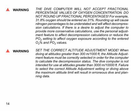
WARNING THE DIVE COMPUTER WILL NOT ACCEPT FRACTIONALPERCENTAGE VALUES OF OXYGEN CONCENTRATION. DONOT ROUND UP FRACTIONAL PERCENTAGES! For example,31.8% oxygen should be entered as 31%. Rounding up will causenitrogen percentages to be understated and will affect decompres-sion calculations. If there is a desire to adjust the computer toprovide more conservative calculations, use the personal adjust-ment feature to affect decompression calculations or reduce thePO2 setting to affect oxygen exposure according to the enteredO2% and PO2 values.
WARNING SET THE CORRECT ALTITUDE ADJUSTMENT MODE! Whendiving at altitudes greater than 300 m/1000 ft, the Altitude Adjust-ment feature must be correctly selected in order for the computerto calculate the decompression status. The dive computer is notintended for use at altitudes greater than 3000 m/10000 ft. Failureto select the correct Altitude Adjustment setting or diving abovethe maximum altitude limit will result in erroneous dive and plan-ning data.
14

WARNING SET THE CORRECT PERSONAL ADJUSTMENT MODE!Whenever it is believed that factors that tend to increase thepossibility of DCI exist, it is recommended that you use this optionto make the calculations more conservative. Failure to select thecorrect Personal Adjustment setting will result in erroneous diveand planning data.
WARNING DO NOT EXCEED THE MAXIMUM ASCENT RATE! Rapid as-cents increase the risk of injury. You should always make theMandatory and Recommended Safety Stops after you have ex-ceeded themaximum recommended ascent rate. If this MandatorySafety Stop is not completed the decompression model will pen-alize your next dive(s).
WARNING YOUR ACTUAL ASCENT TIME MAY BE LONGER THAN DIS-PLAYED BY THE INSTRUMENT! The ascent time will increaseif you:• remain at depth• ascend slower than 10 m/min / 33 ft/min or• make your decompression stop deeper than at the ceilingThese factors will also increase the amount of air required toreach the surface.
15
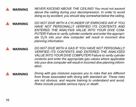
WARNING NEVER ASCEND ABOVE THE CEILING! You must not ascendabove the ceiling during your decompression. In order to avoiddoing so by accident, you should stay somewhat below the ceiling.
WARNING DO NOT DIVE WITH A CYLINDER OF ENRICHED AIR IF YOUHAVE NOT PERSONALLY VERIFIED ITS CONTENTS ANDENTERED THE ANALYSIS VALUE INTO YOUR DIVE COM-PUTER! Failure to verify cylinder contents and enter the appropri-ate O2% into your dive computer will result in incorrect diveplanning information.
WARNING DO NOT DIVE WITH A GAS IF YOU HAVE NOT PERSONALLYVERIFIED ITS CONTENTS AND ENTERED THE ANALYZEDVALUE INTO YOURDIVE COMPUTER! Failure to verify cylindercontents and enter the appropriate gas values where applicableinto your dive computer will result in incorrect dive planning inform-ation.
WARNING Diving with gas mixtures exposes you to risks that are differentfrom those associated with diving with standard air. These risksare not obvious, and require training to understand and avoid.Risks include possible serious injury or death.
16

WARNING Traveling to a higher elevation can temporarily cause a changein the equilibrium of dissolved nitrogen in the body. It is recom-mended that you acclimatize to the new altitude by waiting atleast three hours before diving.
WARNING WHEN THEOXYGEN LIMIT FRACTION INDICATES THAT THEMAXIMUM LIMIT IS REACHED, YOU MUST IMMEDIATELYTAKE ACTION TO REDUCE OXYGEN EXPOSURE. Failure totake action to reduce oxygen exposure after the warning is givencan rapidly increase the risk of oxygen toxicity, injury, or death
WARNING Suunto also recommends that you receive training in Free divingtechniques and physiology before conducting breath hold dives.No dive computer can replace the need for proper dive training.Insufficient or improper trainingmay cause a diver to commit errorsthat may lead to serious injury or death.
WARNING If there are several divers using the dive computer with wirelesstransmission, always ensure that each diver is using a differentcode before starting the dive.
WARNING Personal adjustment setting P0–P-2 causes a high risk of DCI,or other personal injury, and death.
17
WARNING Using the Suunto Dive Planner software is not a substitute forproper dive training. Diving with mixed gases has dangers thatare not familiar to divers diving with air. To dive with trimix, triox,heliox and nitrox or all of them, divers must have specializedtraining for the type of diving they are doing.
WARNING Always use realistic SAC rates and conservative turn pressuresduring dive planning. Overly optimistic or erroneous gas planningcan result in the exhaustion of breathing gas during decompres-sion or in a cave or a wreck.
WARNING ENSURETHEWATERRESISTANCEOFTHEDEVICE!Moistureinside the device or battery compartment will seriously damagethe unit. Only an authorized SUUNTO dealer or distributor shoulddo service activities.
NOTE It is not possible to change between MIXED GAS, and GAUGEmodes before the instrument has counted down the no-fly time.
18
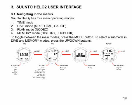
3. SUUNTO HELO2 USER INTERFACE
3.1. Navigating in the menusSuunto HelO2 has four main operating modes:1. TIME mode2. DIVE mode (MIXED GAS, GAUGE)3. PLAN mode (NODEC)4. MEMORY mode (HISTORY, LOGBOOK)To toggle between the main modes, press the MODE button. To select a submode inDIVE and MEMORY modes, press the UP/DOWN buttons.
GasesDepth Alarm
Dive Time AlarmPersonal/Altitude
Sample rateTank Pressure
Tank Pressure AlarmUnits
Mixed gasGauge
LogbookHistory
MEMORY
SUB-MODES
NoDec
PLAN
SUB-MODE
19
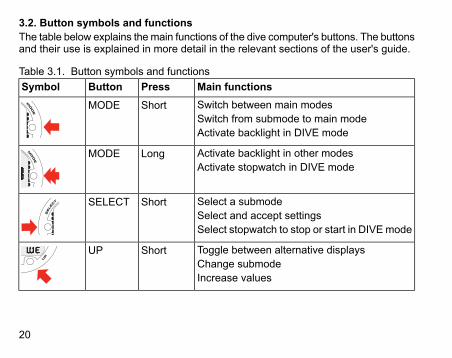
3.2. Button symbols and functionsThe table below explains themain functions of the dive computer's buttons. The buttonsand their use is explained in more detail in the relevant sections of the user's guide.
Table 3.1. Button symbols and functionsMain functionsPressButtonSymbolSwitch between main modesSwitch from submode to main modeActivate backlight in DIVE mode
ShortMODE
Activate backlight in other modesActivate stopwatch in DIVE mode
LongMODE
Select a submodeSelect and accept settingsSelect stopwatch to stop or start in DIVE mode
ShortSELECT
Toggle between alternative displaysChange submodeIncrease values
ShortUP
20

Main functionsPressButtonSymbolActivate gas switching in MIXED GAS modeLongUP
Toggle between alternative displaysChange submodeDecrease values
ShortDOWN
Enter Setting modeLongDOWN
21
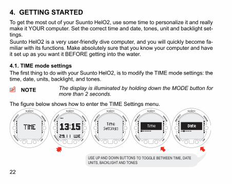
4. GETTING STARTEDTo get the most out of your Suunto HelO2, use some time to personalize it and reallymake it YOUR computer. Set the correct time and date, tones, unit and backlight set-tings.Suunto HelO2 is a very user-friendly dive computer, and you will quickly become fa-miliar with its functions. Make absolutely sure that you know your computer and haveit set up as you want it BEFORE getting into the water.
4.1. TIME mode settingsThe first thing to do with your Suunto HelO2, is to modify the TIME mode settings: thetime, date, units, backlight, and tones.
NOTE The display is illuminated by holding down the MODE button formore than 2 seconds.
The figure below shows how to enter the TIME Settings menu.
USE UP AND DOWN BUTTONS TO TOGGLE BETWEEN TIME, DATEUNITS, BACKLIGHT AND TONES
22
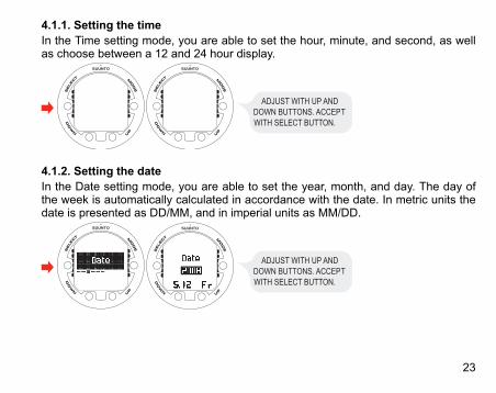
4.1.1. Setting the timeIn the Time setting mode, you are able to set the hour, minute, and second, as wellas choose between a 12 and 24 hour display.
ADJUST WITH UP AND DOWN BUTTONS. ACCEPT WITH SELECT BUTTON.
4.1.2. Setting the dateIn the Date setting mode, you are able to set the year, month, and day. The day ofthe week is automatically calculated in accordance with the date. In metric units thedate is presented as DD/MM, and in imperial units as MM/DD.
ADJUST WITH UP AND DOWN BUTTONS. ACCEPT WITH SELECT BUTTON.
23
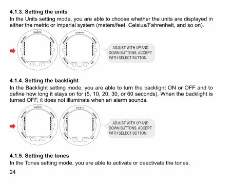
4.1.3. Setting the unitsIn the Units setting mode, you are able to choose whether the units are displayed ineither the metric or imperial system (meters/feet, Celsius/Fahrenheit, and so on).
ADJUST WITH UP AND DOWN BUTTONS. ACCEPT WITH SELECT BUTTON.
4.1.4. Setting the backlightIn the Backlight setting mode, you are able to turn the backlight ON or OFF and todefine how long it stays on for (5, 10, 20, 30, or 60 seconds). When the backlight isturned OFF, it does not illuminate when an alarm sounds.
ADJUST WITH UP AND DOWN BUTTONS. ACCEPT WITH SELECT BUTTON.
4.1.5. Setting the tonesIn the Tones setting mode, you are able to activate or deactivate the tones.
24
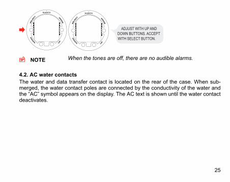
ADJUST WITH UP AND DOWN BUTTONS. ACCEPT WITH SELECT BUTTON.
NOTE When the tones are off, there are no audible alarms.
4.2. AC water contactsThe water and data transfer contact is located on the rear of the case. When sub-merged, the water contact poles are connected by the conductivity of the water andthe “AC” symbol appears on the display. The AC text is shown until the water contactdeactivates.
25
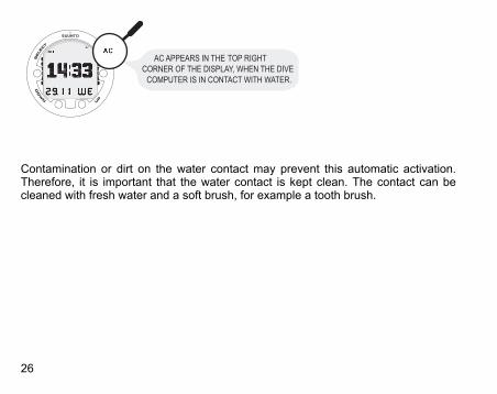
AC APPEARS IN THE TOP RIGHT CORNER OF THE DISPLAY, WHEN THE DIVE
COMPUTER IS IN CONTACT WITH WATER.
Contamination or dirt on the water contact may prevent this automatic activation.Therefore, it is important that the water contact is kept clean. The contact can becleaned with fresh water and a soft brush, for example a tooth brush.
26

5. BEFORE DIVINGDo not attempt to use the dive computer without reading this user's guide in its entirety,including all the warnings. Make sure that you fully understand the use, displays andlimitations of the instrument. If you have any questions about the manual or the divecomputer, contact your SUUNTO dealer before diving with the dive computer.Always remember that YOU ARE RESPONSIBLE FOR YOUR OWN SAFETY!When used properly, Suunto HelO2 is an outstanding tool for assisting properly trained,certified divers in planning and executing technical dives. It is NOT A SUBSTITUTEFORCERTIFIED SCUBA INSTRUCTION, including training in the principles of decom-pression and/or multi-gas diving.
WARNING Diving with gas mixtures exposes you to risks that are differentfrom those associated with diving with standard air. These risksare not obvious, and require training to understand and avoid.Risks include possible serious injury or death.
Do not attempt to dive with any gas mix other than standard air without first receivingcertified training in this specialty.
27
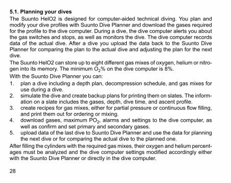
5.1. Planning your divesThe Suunto HelO2 is designed for computer-aided technical diving. You plan andmodify your dive profiles with Suunto Dive Planner and download the gases requiredfor the profile to the dive computer. During a dive, the dive computer alerts you aboutthe gas switches and stops, as well as monitors the dive. The dive computer recordsdata of the actual dive. After a dive you upload the data back to the Suunto DivePlanner for comparing the plan to the actual dive and adjusting the plan for the nextdive.The Suunto HelO2 can store up to eight different gas mixes of oxygen, helium or nitro-gen into its memory. The minimum O2% on the dive computer is 8%.With the Suunto Dive Planner you can:1. plan a dive including a depth plan, decompression schedule, and gas mixes for
use during a dive.2. simulate the dive and create backup plans for printing them on slates. The inform-
ation on a slate includes the gases, depth, dive time, and ascent profile.3. create recipes for gas mixes, either for partial pressure or continuous flow filling,
and print them out for ordering or mixing.4. download gases, maximum PO2, alarms and settings to the dive computer, as
well as confirm and set primary and secondary gases.5. upload data of the last dive to Suunto Dive Planner and use the data for planning
the next dive or for comparing the actual dive to the planned one.After filling the cylinders with the required gas mixes, their oxygen and helium percent-ages must be analyzed and the dive computer settings modified accordingly eitherwith the Suunto Dive Planner or directly in the dive computer.
28

When creating a dive series, the real tissue pressures are calculated by uploading theactual dives to the Suunto Dive Planner with the Suunto Dive Manager. You can thenplan the next dive based on this information.
5.2. The Suunto Technical RGBMSuunto’s Technical RGBM, utilized in the Suunto HelO2, predicts both dissolved andfree gas in the blood and tissues of divers. It is a significant advance on the classicHaldane models, which do not predict free gas. The advantage of Suunto RGBM isadditional safety through its ability to adapt to a variety of situations and dive profiles.
YOU ARE ADVISED TO MAKE A DEEPSTOP AT 18 M. THE SECOND INDICATOR SHOWS THAT YOU HAVE 110 SECONDS LEFT OF YOUR DEEPSTOP.
In order to optimize the response to different increased risk situations, an additionalcategory of stop, referred to as a Mandatory Safety Stop, has been introduced. Thecombination of stop types depends on the user settings and the specific dive situation.To get the most from the RGBM safety benefits, refer to Section 10.2. RGBM.
29

5.3. Emergency ascentsBefore you dive, you must have the dive plan created with the Suunto Dive Plannerprinted out on a slate. You must also have a back-up plan for lost gases. In the unlikelyevent that the dive computer malfunctions during a dive, start using an alternativedepth gauge and timer and following the ascent schedule and gas switches that areon the slate. If you dive using only air, follow these steps:1. Assess the situation calmly and then move promptly to less than 18 m/60 ft.2. At 18 m/60 ft, slow down your ascent rate to 10 m/33 ft per minute and move to
a depth between 3 and 6 m/10 and 20 ft.3. Stay there for as long as your gas supply will safely allow. After reaching the
surface, do not dive for at least 24 hours.In the event that the dive computer functions but a required gas is not available, youcan use your diving partner's gas, which is set as a secondary gas on your dive com-puter. Displayed ASC TIME is not correct, but the decompressions are calculatedcorrectly.In the event that a required gas is not available at all, decompress for as long as youcan by using the next most suitable gas that has the highest oxygen content. Noticethat the oxygen content should be low enough to not violate the maximum partialpressure of oxygen (PO2).
30

5.4. Dive computer limitationsWhile the dive computer is based on current decompression research and technology,you must realize that the computer cannot monitor the actual physiological functionsof an individual diver. All decompression schedules currently known to the authors,including the U.S. Navy Tables, are based on theoretical mathematical models, whichare intended to serve as a guide to reduce the probability of decompression illness.
5.5. Audible and visual alarmsThe dive computer has audible and visual alarms that advise when important limitsare approached or that prompt you to acknowledge preset alarms. The table belowdescribes the different alarms and their meanings.The visual information on the dive computer display is shown during the alarm breaksin order to save battery.
Table 5.1. Audible and visual alarm typesAlarm reasonAlarm indication
PO2 value is greater than the adjustedvalue. Current depth is too deep for thegas in use. You should immediately as-cend or change to a gas with a loweroxygen percentage.
Three beeps with a one second intervalfor the maximum of three minutes. ThePO2 value blinks.
31

Alarm reasonAlarm indicationPO2 value is smaller than 0.18 bar. Thedepth is too shallow and the ambientpressure is too low for the current gas.The oxygen content is too low to keep youconscious. You should immediately switchthe gas.
Three beeps with a one second intervalfor the maximum of 24 seconds. The PO2value blinks.
In MIXED GAS mode, the OLF valuereaches the fixed 80% or 100%. You canacknowledge the alarm.
Two beeps with a one-and-a-half secondinterval. The OLF% value blinks if the PO2value is greater than 0.5 bar.
Decompression ceiling depth is exceeded.You should immediately descend to, orbelow, the ceiling.
Two beeps with a one-and-a-half secondinterval for three minutes. The Er symbolblinks and an arrow points downwards.
Mandatory safety stop is violated. Youshould immediately descend.
Two beeps with a one-and-a-half secondinterval for three minutes. An arrow pointsdownwards.
Maximum allowed ascent rate, 10 m permin / 33 ft per min, is exceeded.
Three beeps with a one second intervalfor 24 seconds. The SLOW symbol blinks.
Mandatory deep stop is violated. Youshould immediately descend.
Two beeps with a one and a half secondinterval for the duration of the deep stopviolation. The DEEP STOP symbol blinksand an arrow points downwards.
32
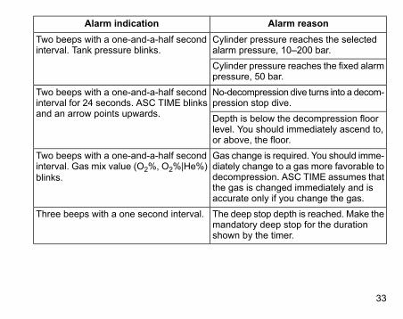
Alarm reasonAlarm indicationCylinder pressure reaches the selectedalarm pressure, 10–200 bar.
Two beeps with a one-and-a-half secondinterval. Tank pressure blinks.
Cylinder pressure reaches the fixed alarmpressure, 50 bar.No-decompression dive turns into a decom-pression stop dive.
Two beeps with a one-and-a-half secondinterval for 24 seconds. ASC TIME blinksand an arrow points upwards. Depth is below the decompression floor
level. You should immediately ascend to,or above, the floor.Gas change is required. You should imme-diately change to a gas more favorable todecompression. ASC TIME assumes thatthe gas is changed immediately and isaccurate only if you change the gas.
Two beeps with a one-and-a-half secondinterval. Gas mix value (O2%, O2%|He%)blinks.
The deep stop depth is reached. Make themandatory deep stop for the durationshown by the timer.
Three beeps with a one second interval.
33
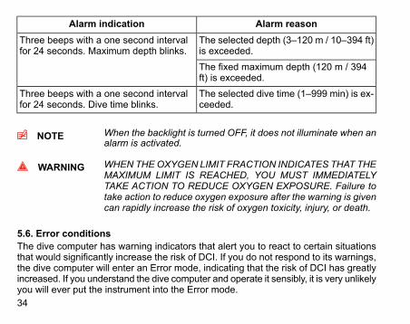
Alarm reasonAlarm indicationThe selected depth (3–120 m / 10–394 ft)is exceeded.
Three beeps with a one second intervalfor 24 seconds. Maximum depth blinks.
The fixed maximum depth (120 m / 394ft) is exceeded.The selected dive time (1–999 min) is ex-ceeded.
Three beeps with a one second intervalfor 24 seconds. Dive time blinks.
NOTE When the backlight is turned OFF, it does not illuminate when analarm is activated.
WARNING WHEN THEOXYGEN LIMIT FRACTION INDICATES THAT THEMAXIMUM LIMIT IS REACHED, YOU MUST IMMEDIATELYTAKE ACTION TO REDUCE OXYGEN EXPOSURE. Failure totake action to reduce oxygen exposure after the warning is givencan rapidly increase the risk of oxygen toxicity, injury, or death.
5.6. Error conditionsThe dive computer has warning indicators that alert you to react to certain situationsthat would significantly increase the risk of DCI. If you do not respond to its warnings,the dive computer will enter an Error mode, indicating that the risk of DCI has greatlyincreased. If you understand the dive computer and operate it sensibly, it is very unlikelyyou will ever put the instrument into the Error mode.34

Out of calculation limitsSuunto uses state of the art memory and microprocessors, however, there are limita-tions to the memory capacity of decompression calculations. Therefore Suunto mustlimit the maximum saturation of tissues on Suunto HelO2 and limit the maximum bottomtimes on dives performed using the dive computer. The bottom times include decom-pression calculation. While it is highly unlikely that the following bottom times areconfronted by open-circuit divers, it is important to warn you of their possibility.The same limits are used in the Suunto Dive Planner and so repetitive dives will bechecked while planning a dive because a dive plan must be created in any case.
Table 5.2. Possible decompression dive timesFirst deep-stop
CeilingBottom timeDepthO2%/He%Gas mix
46 m33 m250 min60 m20/35Tx65 m50 m260 min80 m15/50Tx80 m61 m120 min100 m12/60Tx96 m73 m90 min120 m10/60Tx
Descent at the rate of 10 m/min is included in the time. The times allow for a safe ascentusing the bottom gas all the way to the surface without exceeding tissue pressures.If a diver violates these limits, the dive computer goes to an error mode and the restof the dive must be conducted using the diveplan on the slate.
35

Omitted decompressionThe Error mode results from omitted decompression, for example, when you stayabove the ceiling for more than three minutes. During this three-minute period the Erwarning is shown and the audible alarm beeps. After this, the dive computer enters apermanent Error mode. The instrument will continue to function normally if you descendbelow the ceiling within this three-minute period.When the dive computer is in the permanent Error mode, only the Er warning is shownin the center window. The dive computer does not show times for ascent or stops.However, all the other displays function as before to provide information for ascent.Youshould immediately follow through the decompression schedule in your backup plan.After surfacing, you should not dive for a minimum of 48 hours. During the permanentError mode, the Er text is displayed in the center window and the planning mode isdisabled.
5.7. Wireless transmissionThe HelO2 can be used together with a wireless cylinder pressure transmitter thateasily attaches to the high-pressure port of the regulator. By using the transmitter, youcan benefit from receiving cylinder pressure data direct to your wrist.In order to use the transmitter, the wireless integration needs to be enabled in yourSuunto HelO2 settings. To enable or disable the wireless integration, refer to Sec-tion 5.8.7. Setting the tank pressure.
5.7.1. Installing the wireless transmitterWhen purchasing the Suunto HelO2, we strongly recommend that you have yourSuunto representative attach the transmitter to the first stage of your regulator.36
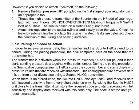
However, if you decide to attach it yourself, do the following:1. Remove the high pressure (HP) port plug on the first stage of your regulator using
an appropriate tool.2. Thread the high pressure transmitter of the Suunto into the HP port of your regu-
lator with your fingers. DO NOT OVERTIGHTEN! Maximum torque is 6 Nm/4.4lbsft or 53 lbsin. The seal is based on a static O-ring, not force!
3. Attach the regulator to the scuba cylinder and slowly open the valve. Check forleaks by submerging the regulator first stage in water. If leaks are detected, checkthe condition of the O-ring and sealing surfaces.
5.7.2. Pairing and code selectionIn order to receive wireless data, the transmitter and the Suunto HelO2 need to bepaired. During the pairing procedure, the dive computer locks on the code that thetransmitter has.The transmitter is activated when the pressure exceeds 15 bar/300 psi and it thenstarts sending pressure data together with a code number. During the pairing procedure,the Suunto dive computersuunto HelO2 stores the code number and starts displayingpressure values that are received with that code. This coding procedure prevents datamix-up from other divers also using a Suunto HelO2 transmitter.When there is no stored code, the Suunto HelO2 displays “cd:--” and receives datawith lowered sensitivity from a very short distance only. By taking the Suunto HelO2unit close to the transmitter, it will store the received code and start receiving with fullsensitivity and display data received with this code only. The code is stored until youreset it manually.
37

NOTE The pairing procedure only needs to performed once, before thefirst use, and you do not need to repair it.
To pair the transmitter and the Suunto HelO2 dive computer:1. Ensure that the transmitter is properly attached to the regulator’s HP port and
that the regulator is properly attached to the cylinder.2. Ensure that the Suunto HelO2 is turned on, and that the wireless integration is
enabled in the Suunto HelO2 settings (HP set ON, refer to Section 5.8.8. Settingthe HP code). The HelO2 should display “cd:--” in the lower left corner of the al-ternative display.
3. Slowly open the cylinder valve fully and pressurize the system. The transmitterstarts transmitting when the pressure exceeds 15 bar/300 psi.
4. Take the Suunto HelO2 unit close to the transmitter. The unit will then quicklydisplay the selected code number and then start displaying the transmitted cylinderpressure. The wireless transmitter indicator (flash symbol) is displayed every timethe Suunto receives a valid signal.
WARNING If there are several divers using Suunto with wireless transmission,always ensure that each diver is using a different code beforestarting the dive.The transmitter's codemust be changed by changing the pressure.You can manually change the transmitter’s code by reducing thepressure to less than 10 bar/145 psi and then immediately (within10-12 seconds) increasing the pressure to above 15 bar/220 psi.
Reset the transmitter's code manually, see Section 5.8.8. Setting the HP code.38
After this, the transmitter selects a new code. The Suunto HelO2 must be in “cd:--“mode to pair on the new code. This procedure can be used if, for example, your divebuddy has the same code and you need to change it.
NOTE In order to save battery energy, the transmitter enters powersaving mode with slower data transmission rate if the tank pres-sure remains unchanged for more than five (5) minutes. Thetransmitter continues transmitting with the saved code when anypressure change is measured.
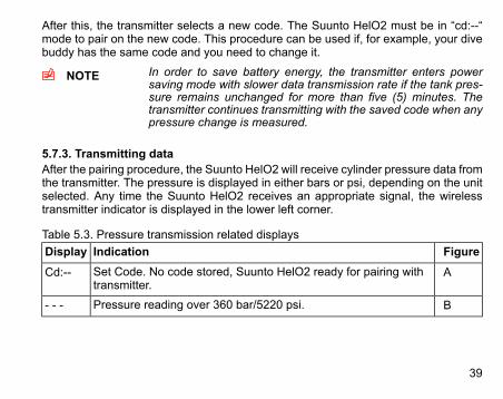
5.7.3. Transmitting dataAfter the pairing procedure, the Suunto HelO2 will receive cylinder pressure data fromthe transmitter. The pressure is displayed in either bars or psi, depending on the unitselected. Any time the Suunto HelO2 receives an appropriate signal, the wirelesstransmitter indicator is displayed in the lower left corner.
Table 5.3. Pressure transmission related displaysFigureIndicationDisplayASet Code. No code stored, Suunto HelO2 ready for pairing with
transmitter.Cd:--
BPressure reading over 360 bar/5220 psi.- - -
39
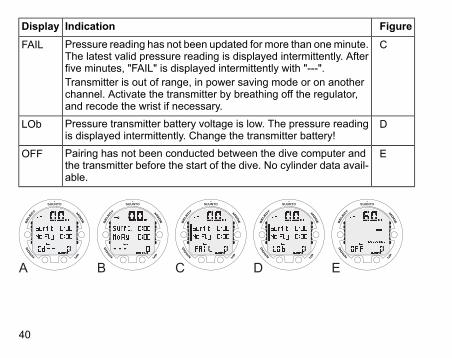
FigureIndicationDisplayCPressure reading has not been updated for more than oneminute.
The latest valid pressure reading is displayed intermittently. Afterfive minutes, "FAIL" is displayed intermittently with "---".Transmitter is out of range, in power saving mode or on anotherchannel. Activate the transmitter by breathing off the regulator,and recode the wrist if necessary.
FAIL
DPressure transmitter battery voltage is low. The pressure readingis displayed intermittently. Change the transmitter battery!
LOb
EPairing has not been conducted between the dive computer andthe transmitter before the start of the dive. No cylinder data avail-able.
OFF
A B C D E
40

5.8. MIXED GAS DIVE mode settingsSuunto HelO2 has several user-definable functions, as well as depth and time-relatedalarms that you can set according to your personal preferences. The DIVE modesettings are dependent on the dive submode chosen (MIXED GAS, GAUGE), so that,for example, gas mix settings are only available in the MIXED GAS submode.With Suunto HelO2, most of the settings are planned with the Suunto Dive Plannerand downloaded to the dive computer. If necessary, they can be changed manually.The figure below shows how to enter the DIVE mode settings menu.
USE UP AND DOWN BUTTONS TO TOGGLE BETWEEN DIVE SETTINGS
NOTE Some settings cannot be changed until five (5) minutes haselapsed after the dive.
41

5.8.1. Setting the gasesIf set to the MIXED GASmode, the correct oxygen and helium percentages of the gasin your cylinders (and additional gases) must always be entered into the dive computerto ensure correct tissue and oxygen calculation. In addition, the oxygen partial pressurelimit must be set. You can either modify the dive plan with the Suunto Dive Planneror enter the correct values directly into the dive computer after analyzing the gas mixesin your cylinders.
ADJUST WITH UP AND DOWN BUTTONS. ACCEPT WITH SELECT BUTTON.
ADJUST WITH UP AND DOWN BUTTONS. ACCEPT WITH SELECT BUTTON.
When in the MIXED GAS setting mode, the equivalent maximum operating depth,based on the chosen setting, is also be displayed.After entering values for Mix1, you can set additional mixes, Mix2–Mix8, similarly. Youcan set them to "PRIMARY", "SECONDARY" or "OFF". Mix1 is always set as a primarygas.In order to minimize the risk of error during a dive, it is highly recommended that themixes are set in the proper order. This means that as the mix number rises, so doesoxygen content, and this is the order they are usually used during the dive. Before adive, only enable the mixes you actually have available and remember to check theset values to ensure they are correct.
42
The ASC time is calculated based on the assumption that you start the ascent profileimmediately and all the PRIMARY gases are changed as soon as their maximum op-erating depth allows it. That is, using the gases that are set as primary, the most op-timal ascent schedule for the moment is calculated.To see the most pessimistic ascent schedule, that is, a schedule for the situation whengases are not changed at all, you can set the gases as secondary and the time it takesto finish the decompression using the current breathing gas is shown as the ASC time.Showing the most pessimistic ascent schedule during a long dive can easily result inthe ascent time no longer fitting the reserved field and the dive computer displays "---" (max. 199 min).
NOTE While setting the gases, notice that the calculated maximum op-erating depth is displayed in the upper field. You cannot changeto this gas before you have ascended above this depth.
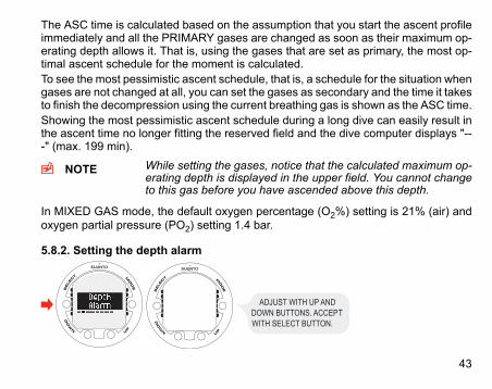
In MIXED GAS mode, the default oxygen percentage (O2%) setting is 21% (air) andoxygen partial pressure (PO2) setting 1.4 bar.
5.8.2. Setting the depth alarm
ADJUST WITH UP AND DOWN BUTTONS. ACCEPT WITH SELECT BUTTON.
43
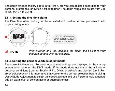
The depth alarm is factory-set to 50 m/160 ft, but you can adjust it according to yourpersonal preference, or switch it off altogether. The depth range can be set from 3 mto 120 m/10 ft to 394 ft.
5.8.3. Setting the dive-time alarmThe Dive Time Alarm setting can be activated and used for several purposes to addto your diving safety.
ADJUST WITH UP AND DOWN BUTTONS. ACCEPT WITH SELECT BUTTON.
NOTE With a range of 1–999 minutes, the alarm can be set to yourplanned bottom time, for example.
5.8.4. Setting the personal/altitude adjustmentsThe current Altitude and Personal Adjustment settings are displayed in the startupscreen when entering the DIVE mode. If the mode does not match the altitude orpersonal conditions (refer to Section 5.9.4. Diving at altitude and Section 5.9.5. Per-sonal adjustments), it is imperative that you enter the correct selection before diving.Use Altitude Adjustment to select the correct altitude and use Personal Adjustment toadd an extra level of conservatism or aggressiveness.
44
ADJUST WITH UP AND DOWN BUTTONS. ACCEPTWITH SELECT BUTTON.
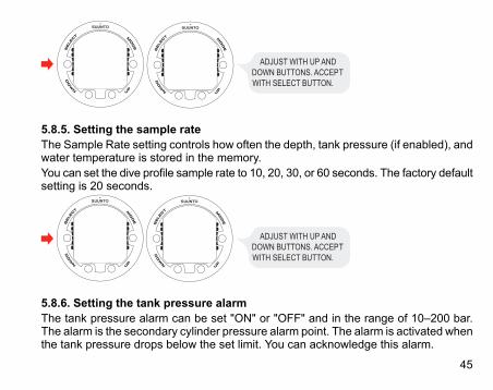
5.8.5. Setting the sample rateThe Sample Rate setting controls how often the depth, tank pressure (if enabled), andwater temperature is stored in the memory.You can set the dive profile sample rate to 10, 20, 30, or 60 seconds. The factory defaultsetting is 20 seconds.
ADJUST WITH UP AND DOWN BUTTONS. ACCEPTWITH SELECT BUTTON.
5.8.6. Setting the tank pressure alarmThe tank pressure alarm can be set "ON" or "OFF" and in the range of 10–200 bar.The alarm is the secondary cylinder pressure alarm point. The alarm is activated whenthe tank pressure drops below the set limit. You can acknowledge this alarm.
45
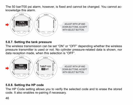
The 50 bar/700 psi alarm, however, is fixed and cannot be changed. You cannot ac-knowledge this alarm.
ADJUST WITH UP AND DOWN BUTTONS. ACCEPTWITH SELECT BUTTON.
5.8.7. Setting the tank pressureThe wireless transmission can be set “ON” or “OFF” depending whether the wirelesspressure transmitter is used or not. No cylinder pressure-related data is shown, nordata reception made, when this selection is “OFF”.
ADJUST WITH UP AND DOWN BUTTONS. ACCEPT WITH SELECT BUTTON.
5.8.8. Setting the HP codeThe HP Code setting allows you to verify the selected code and to erase the storedcode. It also enables re-pairing if necessary.
46

ADJUST WITH UP AND DOWN BUTTONS. ACCEPTWITH SELECT BUTTON.
SELECT TANK PRESSURE ON.
5.8.9. Setting the unitsIn the Unit settings you are able to choose between metric (meters/Celsius/bar) andimperial (feet/Fahrenheit/psi) units.
ADJUST WITH UP AND DOWN BUTTONS. ACCEPTWITH SELECT BUTTON.
5.9. Activation and pre-checksThis section describes how to activate the DIVE mode and explains the pre-checksthat it is highly recommended you perform before you get into the water.
47

5.9.1. Accessing DIVE modeThe Suunto HelO2 has two diving modes: MIXEDGASmode for diving with gas mixesand GAUGE mode for use as a bottom timer.The chosen dive mode is displayed when the DIVE mode is accessed, and you cantoggle between the submodes by pressing the UP/DOWN buttons.
5.9.2. DIVE mode activationThe dive computer activates automatically when submerged deeper than 0.5 m/1.5ft. However, it is necessary to activate the DIVE mode BEFORE diving to checkthe altitude and personal adjustment settings, battery condition, oxygen settings,and so on.After activation, all graphical display elements are turned ON, and the backlight andthe beep are activated. A few seconds later the battery power indicator is shown.
48
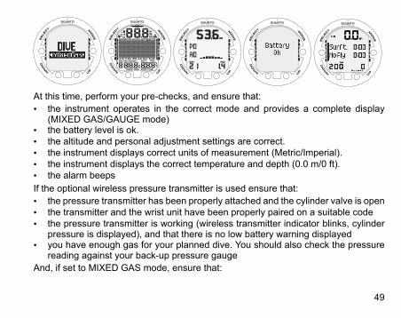
At this time, perform your pre-checks, and ensure that:• the instrument operates in the correct mode and provides a complete display
(MIXED GAS/GAUGE mode)• the battery level is ok.• the altitude and personal adjustment settings are correct.• the instrument displays correct units of measurement (Metric/Imperial).• the instrument displays the correct temperature and depth (0.0 m/0 ft).• the alarm beepsIf the optional wireless pressure transmitter is used ensure that:• the pressure transmitter has been properly attached and the cylinder valve is open• the transmitter and the wrist unit have been properly paired on a suitable code• the pressure transmitter is working (wireless transmitter indicator blinks, cylinder
pressure is displayed), and that there is no low battery warning displayed• you have enough gas for your planned dive. You should also check the pressure
reading against your back-up pressure gaugeAnd, if set to MIXED GAS mode, ensure that:
49
• the correct number of mixes is set and that the oxygen and helium percentagesare adjusted according to the measured gas blends in your cylinders
• the oxygen partial pressure limits are set correctlyFor more information on the MIXED GAS mode, please refer to Section 6.2. Diving inMIXED GAS mode .The dive computer is now ready for diving.
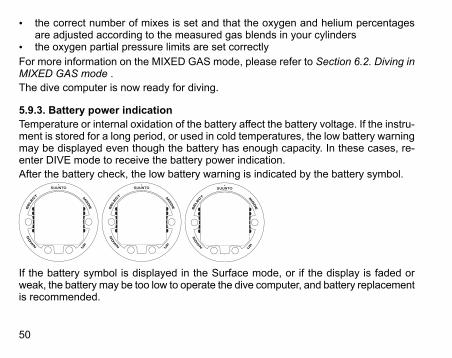
5.9.3. Battery power indicationTemperature or internal oxidation of the battery affect the battery voltage. If the instru-ment is stored for a long period, or used in cold temperatures, the low battery warningmay be displayed even though the battery has enough capacity. In these cases, re-enter DIVE mode to receive the battery power indication.After the battery check, the low battery warning is indicated by the battery symbol.
If the battery symbol is displayed in the Surface mode, or if the display is faded orweak, the battery may be too low to operate the dive computer, and battery replacementis recommended.
50

NOTE For safety reasons, the backlight cannot be activated when thelow battery warning is indicated by the battery symbol.
The optional wireless pressure transmitter sends out a low battery (batt) warning whenits battery voltage is getting low. This is shown intermittently instead of the pressurereading. When you get this warning, the pressure transmitter's battery needs to bereplaced.
5.9.4. Diving at altitudeThe dive computer can be adjusted both for diving at altitude and also to increase theconservatism of the mathematical nitrogen model.When programming the instrument for the correct altitude, you need to select thecorrect Altitude Adjustment settings according to Table 5.4, Altitude Adjustment settings.The dive computer will adjust its mathematical model according to the entered altitudesetting, giving shorter no-decompression times at higher altitudes.
Table 5.4. Altitude Adjustment settingsAltitude rangeAlt. adjustment
value0–300 m / 0–1000 ftA0
300–1500 m / 1000–5000 ftA1
1500–3000 m / 5000–10 000 ftA2
51
NOTE Section 5.8.4. Setting the personal/altitude adjustments describeshow the Altitude value is set.
WARNING Traveling to a higher elevation can temporarily cause a changein the equilibrium of dissolved nitrogen in the body. It is recom-mended that you acclimatize to the new altitude by waiting atleast three (3) hours before diving.
5.9.5. Personal adjustmentsThere are personal factors that can affect your susceptibility to DCI, which you canpredict in advance, and input into the decompressionmodel. Such factors vary betweendivers and also for the same diver from one day to another. The five-step PersonalAdjustment setting is available if a more conservative or aggressive dive plan is desired.The personal factors which tend to increase the possibility of DCI include, but are notlimited to:• cold exposure —water temperature less than 20 °C/68 °F• below average physical fitness level• fatigue• dehydration• previous history of DCI• stress• obesity• patent foramen ovale (PFO)• exercise on or after dive52
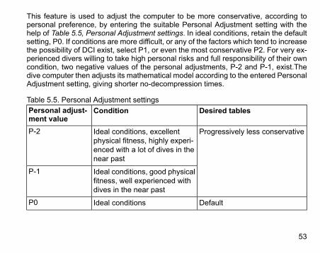
This feature is used to adjust the computer to be more conservative, according topersonal preference, by entering the suitable Personal Adjustment setting with thehelp of Table 5.5, Personal Adjustment settings. In ideal conditions, retain the defaultsetting, P0. If conditions are more difficult, or any of the factors which tend to increasethe possibility of DCI exist, select P1, or even the most conservative P2. For very ex-perienced divers willing to take high personal risks and full responsibility of their owncondition, two negative values of the personal adjustments, P-2 and P-1, exist.Thedive computer then adjusts its mathematical model according to the entered PersonalAdjustment setting, giving shorter no-decompression times.
Table 5.5. Personal Adjustment settingsDesired tablesConditionPersonal adjust-
ment valueProgressively less conservativeIdeal conditions, excellent
physical fitness, highly experi-enced with a lot of dives in thenear past
P-2
Ideal conditions, good physicalfitness, well experienced withdives in the near past
P-1
DefaultIdeal conditionsP0
53
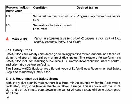
Desired tablesConditionPersonal adjust-ment value
Progressively more conservativeSome risk factors or conditionsexist
P1
Several risk factors or condi-tions exist
P2
WARNING Personal adjustment setting P0–P-2 causes a high risk of DCI,or other personal injury, and death.
5.10. Safety StopsSafety Stops are widely considered good diving practice for recreational and technicaldiving, and are an integral part of most dive tables. The reasons for performing aSafety Stop include: reducing sub-clinical DCI, microbubble reduction, ascent control,and orientation before surfacing.The Suunto HelO2 displays two different types of Safety Stops: Recommended SafetyStop and Mandatory Safety Stop.
5.10.1. Recommended Safety StopsWith every dive over 10 meters, there is a three-minute countdown for the Recommen-ded Safety Stop, to be taken in the 3–6m/10–20 ft range. This is shown with the STOPsign and a three-minute countdown in the center window instead of the no-decompres-sion time.54
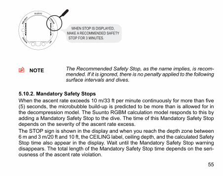
WHEN STOP IS DISPLAYED, MAKE A RECOMMENDED SAFETY STOP FOR 3 MINUTES.
NOTE The Recommended Safety Stop, as the name implies, is recom-mended. If it is ignored, there is no penalty applied to the followingsurface intervals and dives.
5.10.2. Mandatory Safety StopsWhen the ascent rate exceeds 10 m/33 ft per minute continuously for more than five(5) seconds, the microbubble build-up is predicted to be more than is allowed for inthe decompression model. The Suunto RGBM calculation model responds to this byadding a Mandatory Safety Stop to the dive. The time of this Mandatory Safety Stopdepends on the severity of the ascent rate excess.The STOP sign is shown in the display and when you reach the depth zone between6 m and 3 m/20 ft and 10 ft, the CEILING label, ceiling depth, and the calculated SafetyStop time also appear in the display. Wait until the Mandatory Safety Stop warningdisappears. The total length of the Mandatory Safety Stop time depends on the seri-ousness of the ascent rate violation.
55
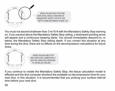
WHEN CEILING AND STOP ARE DISPLAYED, MAKE A ONE MINUTE MANDATORY SAFETY STOP IN THE
DEPTH ZONE BETWEEN 6 M AND 3 M.
Youmust not ascend shallower than 3 m/10 ft with the Mandatory Safety Stop warningon. If you ascend above the Mandatory Safety Stop ceiling, a downward pointing arrowwill appear and a continuous beeping starts. You should immediately descend to, orbelow, the Mandatory Safety Stop ceiling depth. If you correct this situation at anytime during the dive, there are no effects on the decompression calculations for futuredives.
WHEN CEILING AND STOP ARE DISPLAYED, IMMEDIATELY (WITHIN 3 MINUTES) DESCEND
TO OR BELOW CEILING.
If you continue to violate the Mandatory Safety Stop, the tissue calculation model isaffected and the dive computer shortens the available no-decompression time for yournext dive. In this situation, it is recommended that you prolong your surface intervaltime before your next dive.56
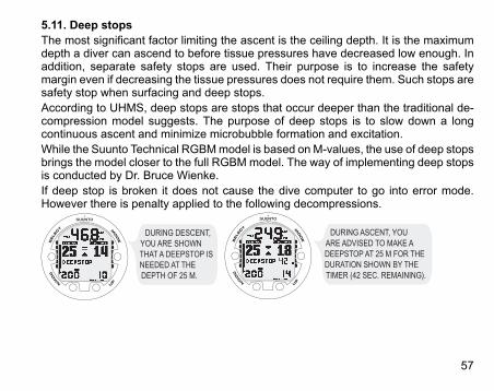
5.11. Deep stopsThe most significant factor limiting the ascent is the ceiling depth. It is the maximumdepth a diver can ascend to before tissue pressures have decreased low enough. Inaddition, separate safety stops are used. Their purpose is to increase the safetymargin even if decreasing the tissue pressures does not require them. Such stops aresafety stop when surfacing and deep stops.According to UHMS, deep stops are stops that occur deeper than the traditional de-compression model suggests. The purpose of deep stops is to slow down a longcontinuous ascent and minimize microbubble formation and excitation.While the Suunto Technical RGBMmodel is based on M-values, the use of deep stopsbrings the model closer to the full RGBMmodel. The way of implementing deep stopsis conducted by Dr. Bruce Wienke.If deep stop is broken it does not cause the dive computer to go into error mode.However there is penalty applied to the following decompressions.
DURING DESCENT, YOU ARE SHOWN THAT A DEEPSTOP IS NEEDED AT THE DEPTH OF 25 M.
DURING ASCENT, YOU ARE ADVISED TO MAKE A DEEPSTOP AT 25 M FOR THE DURATION SHOWN BY THE TIMER (42 SEC. REMAINING).
57
6. DIVINGThis section contains instructions on how to operate the dive computer and interpretits displays. The dive computer is easy to use and read. Each display shows only thedata relevant to that specific diving mode.
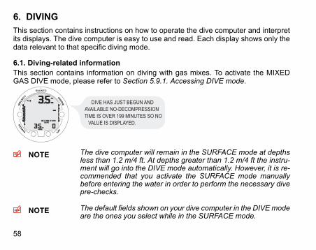
6.1. Diving-related informationThis section contains information on diving with gas mixes. To activate the MIXEDGAS DIVE mode, please refer to Section 5.9.1. Accessing DIVE mode.
DIVE HAS JUST BEGUN AND AVAILABLE NO-DECOMPRESSION TIME IS OVER 199 MINUTES SO NO
VALUE IS DISPLAYED.
NOTE The dive computer will remain in the SURFACE mode at depthsless than 1.2 m/4 ft. At depths greater than 1.2 m/4 ft the instru-ment will go into the DIVE mode automatically. However, it is re-commended that you activate the SURFACE mode manuallybefore entering the water in order to perform the necessary divepre-checks.
NOTE The default fields shown on your dive computer in the DIVEmodeare the ones you select while in the SURFACE mode.
58

6.1.1. Basic dive dataDuring a No-decompression dive, the following information is displayed:• your present depth in meters/feet• the available no-decompression time in minutes as NO DEC TIME• the ascent rate presented as a bar graph on the right side
DIVE DISPLAY - PRESENT DEPTH IS 15 M, MAX DEPTH OF DIVE IS 33.5 M ANDNO-DECOMPRESSION STOP TIME LIMIT IS 38 MIN.ELAPSED DIVE TIME IS 13 MIN.
Alternative displays, by pressing the UP/DOWN buttons, show:• the elapsed dive time in minutes, shown as DIVE TIME• the water temperature in °C/°F• the maximum depth during this dive in meters/feet, indicated as MAX• the current time, shown as TIME
UP BUTTON TOGGLES BETWEEN DIVE TIME AND WATER TEMPERATURE.
59
In addition, with the optional wireless transmission enabled:• the cylinder pressure in bar (or psi) displayed in the lower left corner• the cylinder pressure graphically displayed on the left side
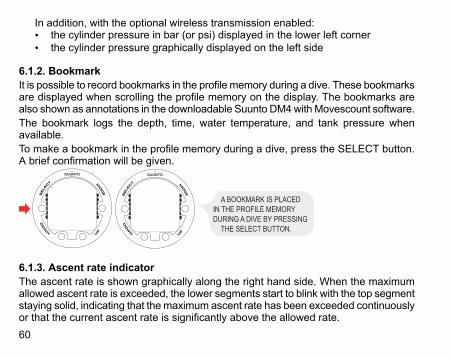
6.1.2. BookmarkIt is possible to record bookmarks in the profile memory during a dive. These bookmarksare displayed when scrolling the profile memory on the display. The bookmarks arealso shown as annotations in the downloadable Suunto DM4withMovescount software.The bookmark logs the depth, time, water temperature, and tank pressure whenavailable.To make a bookmark in the profile memory during a dive, press the SELECT button.A brief confirmation will be given.
A BOOKMARK IS PLACED IN THE PROFILE MEMORY DURING A DIVE BY PRESSING
THE SELECT BUTTON.
6.1.3. Ascent rate indicatorThe ascent rate is shown graphically along the right hand side. When the maximumallowed ascent rate is exceeded, the lower segments start to blink with the top segmentstaying solid, indicating that the maximum ascent rate has been exceeded continuouslyor that the current ascent rate is significantly above the allowed rate.60
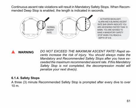
Continuous ascent rate violations will result in Mandatory Safety Stops. When Recom-mended Deep Stop is enabled, the length is indicated in seconds.
NORMAL ASCENT RATE.
ACTIVATED BACKLIGHT, ALARM AND A BLINKING ASCENT
RATE BAR GRAPH INDICATE YOU ARE ASCENDING FASTER THAN 10 M/MIN. YOU ARE ADVISED TO MAKE A MANDATORY SAFETY STOP WHEN YOU REACH A DEPTH OF 6 M.
WARNING DO NOT EXCEED THE MAXIMUM ASCENT RATE! Rapid as-cents increase the risk of injury. You should always make theMandatory and Recommended Safety Stops after you have ex-ceeded themaximum recommended ascent rate. If this MandatorySafety Stop is not completed, the decompression model willpenalize your next dive(s).
6.1.4. Safety StopsA three (3) minute Recommended Safety Stop is prompted after every dive to over10 m.
61
6.1.5. Decompression divesWhen your NO DEC TIME becomes zero, your dive changes into a decompressiondive. Therefore, you must perform one or more decompression stops on your way tothe surface. The NO DEC TIME on your display will be replaced by an ASC TIME,and a CEILING notation will appear. An upward pointing arrow will also prompt youto start your ascent.If you exceed the no-decompression limits on a dive, the dive computer will providethe decompression information required for ascent. After this, the instrument willcontinue to provide subsequent interval and repetitive dive information.Rather than requiring you to make stops at fixed depths, the dive computer lets youdecompress within a range of depths (continuous decompression).The ascent time (ASC TIME) is the minimum amount of time needed to reach thesurface in a decompression dive. It includes:• the time needed at the deep stop• the time needed to ascend to the ceiling at an ascent rate of 10 m/33 ft per minute.
The ceiling is the shallowest depth to which you should ascend.• the time needed at the ceiling• the time needed at the Mandatory Safety Stop (if any)• the time needed to reach the surface after the ceiling and Safety Stops have been
completed
62

WARNING YOUR ACTUAL ASCENT TIME MAY BE LONGER THAN DIS-PLAYED BY THE INSTRUMENT! The ascent time will increaseif you:• do not use optimal decompression gas• remain at depth• ascend slower than 10 m/33 ft per minute or• make your decompression stop deeper than at the ceilingThese factors will also increase the amount of gas required toreach the surface.
Ceiling, ceiling zone, floor and decompression rangeWhen in decompression, it is important that you understand the meaning of ceiling,floor, and decompression range.• The ceiling is the shallowest depth to which you should ascend when in decom-
pression. At this depth, or below, you must perform all stops.• The ceiling zone is the optimum decompression stop zone. It is the zone between
the minimum ceiling and 1.2 m/4 ft below the minimum ceiling.• The floor is the deepest depth at which the decompression stop time will not in-
crease. Decompression will start when you pass this depth during your ascent.• The decompression range is the depth range between the ceiling and floor. Within
this range, decompression takes place. However, it is important to remember thatthe decompression will be very slow at, or close to, the floor.
63
The depth of the ceiling and floor depends on your dive profile. The ceiling depth willbe fairly shallow when you enter the decompression mode, but if you remain at depth,it will move downward and the ascent time will increase. Likewise, the floor and ceilingmay change upwards while you are decompressing.When conditions are rough, it may be difficult to maintain a constant depth near thesurface. In such cases, it is more manageable to maintain an additional distance belowthe ceiling, to ensure that the waves do not lift you above the ceiling. Suunto recom-mends that decompression takes place deeper than 4 m/13 ft, even if the indicatedceiling is shallower.
NOTE It will take more time and more gas to decompress below theceiling than at the ceiling.
WARNING NEVER ASCEND ABOVE THE CEILING! You must not ascendabove the ceiling during your decompression. In order to avoiddoing so by accident, you should stay somewhat below the ceiling.
64
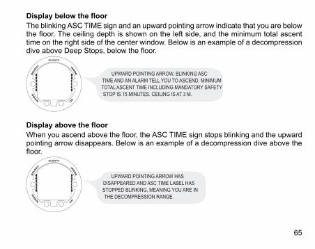
Display below the floorThe blinking ASC TIME sign and an upward pointing arrow indicate that you are belowthe floor. The ceiling depth is shown on the left side, and the minimum total ascenttime on the right side of the center window. Below is an example of a decompressiondive above Deep Stops, below the floor.
UPWARD POINTING ARROW, BLINKING ASC TIME AND AN ALARM TELL YOU TO ASCEND. MINIMUM TOTAL ASCENT TIME INCLUDING MANDATORY SAFETY STOP IS 15 MINUTES. CEILING IS AT 3 M.
Display above the floorWhen you ascend above the floor, the ASC TIME sign stops blinking and the upwardpointing arrow disappears. Below is an example of a decompression dive above thefloor.
UPWARD POINTING ARROW HAS DISAPPEARED AND ASC TIME LABEL HAS STOPPED BLINKING, MEANING YOU ARE IN THE DECOMPRESSION RANGE.
65

Decompression will now begin, but is very slow. Therefore, you should continue yourascent.
Display at the ceiling zoneWhen you reach the ceiling zone, the display will show you two arrows pointing ateach other (the “hour glass” icon). Below is an example of a decompression dive atthe ceiling zone.
TWO ARROWS POINT AT EACH OTHER “HOUR GLASS”. YOU ARE IN THE OPTIMUM CEILING ZONE AT 3 M. AND YOUR MINIMUM ASCENT TIME IS 15 MINUTES.
During the decompression stop, ASC TIME will count down towards zero. When theceiling moves upwards, you can ascend to the new ceiling. You may surface only afterthe ASC TIME and CEILING labels have disappeared, which means that the decom-pression stop and any Mandatory Safety Stop have been completed. You are advised,however, to stay until the STOP sign has also disappeared. This indicates that thethree (3) minute Recommended Safety Stop has also been completed.
Display above the ceilingIf you ascend above the ceiling during a decompression stop, a downward pointingarrow will appear and a continuous beeping starts.
66
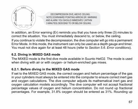
DECOMPRESSION DIVE, ABOVE CEILING. NOTE DOWNWARD POINTING ARROW, ER WARNING AND ALARM. YOU SHOULD IMMEDIATLY (WITHIN 3 MINUTES) DESCEND TO OR BELOW CEILING.
In addition, an Error warning (Er) reminds you that you have only three (3) minutes tocorrect the situation. You must immediately descend to, or below, the ceiling.If you continue to violate the decompression, the dive computer will go into a permanentError Mode. In this mode, the instrument can only be used as a depth gauge and timer.You must not dive again for at least 48 hours (refer to Section 5.6. Error conditions).
6.2. Diving in MIXED GAS modeThe MIXED mode is the first dive mode available in Suunto HelO2. The mode is usedwhen diving with air or with oxygen- or helium-enriched gas mixes.
6.2.1. Before diving in the MIXED GAS modeIf set to the MIXED GAS mode, the correct oxygen and helium percentage of the gasin your cylinders must always be entered into the computer to ensure correct inert gasand oxygen calculations. The dive computer adjusts its mathematical inert gas andoxygen calculation models accordingly. The dive computer will not accept fractionalpercentage values of oxygen and helium concentration. Do not round up fractionalpercentages. For example, 31.8% oxygen should be entered as 31%. Rounding up
67
will cause inert gas percentages to be understated and will affect decompressioncalculations. If you want to adjust the computer to provide more conservative calcula-tions, use the personal adjustment feature to affect decompression calculations, orreduce the PO2 setting to affect oxygen exposure according to the entered O2% andPO2 values. Calculations based on nitrox use result in longer no-decompression timesand shallower maximum depths than diving with air.As a safety precaution, the oxygen calculations in the computer are made with anoxygen percentage of 1% + set O2%.When the dive computer is set in MIXEDGASmode, the Dive Planningmode calculatesusing the O2% and PO2 values that are currently in the computer.To set the nitrox, trimix and/or heliox mixes, refer to Section 5.8.1. Setting the gases.
Default gas mix settingsIn theMIXEDGASmode, the Suunto HelO2 allows you to set 1–8 gasmixes containing8–99% oxygen and 0–92% helium.In the MIXED GAS mode, the default setting is standard air (21% O2 and 0% He). Itremains in this setting until the O2% is adjusted to any other percentage of oxygen(8%–99%). The default setting for maximum oxygen partial pressure is 1.4 bar, howeveryou are able to set it in the range of 0.5–1.6 bar.
6.2.2. Oxygen and helium displaysWhen the MIXED GAS mode is activated, the display will show the information in thefigure below. In the MIXED GAS mode, the maximum operational depth is calculatedbased on set O2%, He% and PO2 values.
68
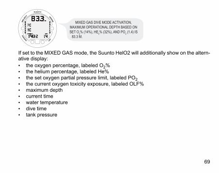
MIXED GAS DIVE MODE ACTIVATION, MAXIMUM OPERATIONAL DEPTH BASED ON SET O2% (14%), HE2% (32%), AND PO2 (1.4) IS
83.3 M.
If set to the MIXED GAS mode, the Suunto HelO2 will additionally show on the altern-ative display:• the oxygen percentage, labeled O2%• the helium percentage, labeled He%• the set oxygen partial pressure limit, labeled PO2• the current oxygen toxicity exposure, labeled OLF%• maximum depth• current time• water temperature• dive time• tank pressure
69
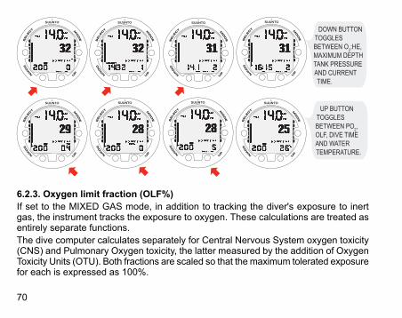
UP BUTTON TOGGLES BETWEEN PO2, OLF, DIVE TIME AND WATER TEMPERATURE.
DOWN BUTTON TOGGLES BETWEEN O2:HE, MAXIMUM DEPTH TANK PRESSURE AND CURRENT TIME.
6.2.3. Oxygen limit fraction (OLF%)If set to the MIXED GAS mode, in addition to tracking the diver's exposure to inertgas, the instrument tracks the exposure to oxygen. These calculations are treated asentirely separate functions.The dive computer calculates separately for Central Nervous System oxygen toxicity(CNS) and Pulmonary Oxygen toxicity, the latter measured by the addition of OxygenToxicity Units (OTU). Both fractions are scaled so that the maximum tolerated exposurefor each is expressed as 100%.
70
The Oxygen Limit Fraction (OLF%) displays only the value of the higher of the twocalculations. The oxygen toxicity calculations are based on the factors listed in Sec-tion 10.3. Oxygen exposure .
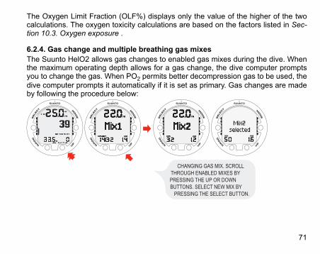
6.2.4. Gas change and multiple breathing gas mixesThe Suunto HelO2 allows gas changes to enabled gas mixes during the dive. Whenthe maximum operating depth allows for a gas change, the dive computer promptsyou to change the gas. When PO2 permits better decompression gas to be used, thedive computer prompts it automatically if it is set as primary. Gas changes are madeby following the procedure below:
CHANGING GAS MIX. SCROLL THROUGH ENABLED MIXES BY PRESSING THE UP OR DOWN BUTTONS. SELECT NEW MIX BY
PRESSING THE SELECT BUTTON.
71
NOTE Mix number, O2%, He and PO2 for the mixes are shown whenscrolling. If the set PO2 limit is exceeded , it will be shown withthe PO2 value blinking. The dive computer does not allow you tochange to a gas whose set PO2 is exceeded. In such a case, themix is shown but cannot be selected. If the PO2 is less than 0.18bar, the dive computer gives an alarm.
NOTE If no button is pressed in 15 seconds, the dive computer will goback to the dive display without changing the gas mix. Upon as-cent, the computer prompts you to change gas when the PO2level you have set for the next mix allows a gas change. Theprompt is an audible 3 beeps and the current O2 or O2 : He mixstarts to blink.
6.3. Diving in the GAUGE modeIf set to the GAUGE mode, the dive computer can be used as a bottom timer.In the GAUGE mode, the total dive time is always displayed in minutes in the lowerright corner. In addition, a Dive Timer in the center window displays time in minutesand seconds. The center window Dive Timer is activated at the start of the dive andit can be reset during the dive and used as a stopwatch by pressing the SELECTbutton.
72

BY PRESSING THE SELECT BUTTON DURING A DIVE, A BOOKMARK IS WRITTEN IN THE PROFILE MEMORY, THE DIVE TIMER IS RESET,AND THE PREVIOUSLY-TIMED INTERVAL IS DISPLAYED BELOW.
Tank pressure (if enabled) is also displayed during the dive.
NOTE The GAUGEmode does not provide decompression information.
NOTE If you dive with the GAUGE mode, it is not possible to changebetween the modes before the no fly time (48 h) has counteddown.
73

7. AFTER DIVINGOnce back at the surface, Suunto HelO continues to provide post-dive safety inform-ation and alarms. Calculations to enable repetitive dive planning also help to maximizediver safety.
Table 7.1. AlarmsIndicationSymbol on displayDiver Attention Symbol - Extend Surface Interval
Violated Decompression Ceiling or Too Long BottomTime
Do Not Fly Symbol
7.1. Surface intervalAn ascent to any depth shallower than 1.2 m/4 ft will cause the DIVE display to bereplaced by the SURFACE display:
IT IS 15 MINUTES SINCE YOU SURFACED FROM A 6-MINUTE DIVE. THE PRESENT DEPTH IS
0.0 M. THE AIRPLANE SYMBOL AND NO-FLY VALUE INDICATE THAT YOU SHOULD NOT FLY FOR 20
HOURS.
74
Or, in the alternative displays, the following information will be shown:• maximum depth of last dive in meters/feet• dive time of last dive in minutes, shown as DIVE TIME• the current time, shown as TIME• the current temperature in °C/°FIf set to MIXED GAS mode, the following information will also be shown:• the oxygen percentage labeled O2%• the helium percentage labeled He%• the oxygen partial pressure labeled PO2• the current oxygen toxicity exposure labeled OLF%
7.2. Dive numberingSeveral repetitive dives are considered to belong to the same repetitive dive serieswhen the dive computer has not counted the no-fly time to zero. Within each series,the dives are given individual numbers. The first dive of the series will be numberedas DIVE 1, the second as DIVE 2, the third as DIVE 3, and so on.If you start a new dive with less than five (5) minutes of surface interval time, the divecomputer interprets this as a continuation of the previous dive and the dives are con-sidered to be the same. The diving display will return, the dive number will remainunchanged, and the dive time will begin where it left off. After five (5) minutes on thesurface, subsequent dives are, by definition, repetitive. The dive counter displayed inthe Planning mode will increment to the next number if another dive is made.
75
7.3. Repetitive dive planningThe Suunto HelO2 includes a dive planner that allows you to review the no-decom-pression limits on a subsequent dive, taking the residual nitrogen loading of previousdives into consideration. The dive plan mode is not meant for technical dive planningwhich the Suunto Dive Planner PC software is meant for. However, the dive plan modecan be used to plan short recreational dives.The PC software takes the residual inert gas of the previous dives into considerationwhen the dive profile is downloaded from the dive computer. It is also possible to checkhow the planned air consumption corresponded to the actual air consumption. TheDIVE PLANNING mode is explained in Section 7.5.1. DIVE PLANNING mode (PLANNoDec).
7.4. Flying after divingIn the DIVEmode, the no-fly time is displayed in the center window next to the airplaneimage. In the TIME mode, the airplane image is shown in the top left corner.The no-fly time and the surface time are shown in the TIME mode as well. Flying or travelingto a higher altitude should be avoided at any time when the computer is counting downthe no-fly time.The no-fly time is always at least 12 hours, or equivalent to the so-called desaturationtime (if longer than 12 hours). For desaturation times lower than 70 minutes, no no-fly time is given.In the Permanent Error mode and GAUGE mode, the no-fly time is 48 hours.The Divers Alert Network (DAN) recommends the following on no-fly times:
76
• A minimum surface interval of 12 hours would be required in order to be reasonablyassured a diver will remain symptom free upon ascent to altitude in a commercialjetliner (altitude up to 2,400 m/8,000 ft).
• Divers who plan to make daily, multiple dives for several days, or make dives thatrequire decompression stops, should take special precautions and wait for an ex-tended interval beyond 12 hours before a flight. Further, the Undersea and Hyper-baric Medical Society (UHMS) suggests divers using standard air cylinders andexhibiting no symptoms of decompression illness wait 24 hours after their last diveto fly in an aircraft with cabin pressure up to 2,400 m/8,000 ft. The only two excep-tions to this recommendation are:• If a diver has less than two (2) hours total accumulated dive time in the last 48
hours, a 12 hour surface interval before flying is recommended.• Following any dive that required a decompression stop, flying should be delayed
for at least 24 hours, and if possible, for 48 hours.• Suunto recommends that flying is avoided until all the DAN and UHMS guidelines,
as well as the dive computer’s no-fly conditions, are satisfied.
77
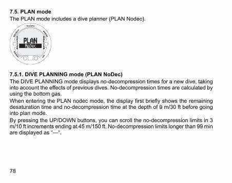
7.5. PLAN modeThe PLAN mode includes a dive planner (PLAN Nodec).
7.5.1. DIVE PLANNING mode (PLAN NoDec)The DIVE PLANNING mode displays no-decompression times for a new dive, takinginto account the effects of previous dives. No-decompression times are calculated byusing the bottom gas.When entering the PLAN nodec mode, the display first briefly shows the remainingdesaturation time and no-decompression time at the depth of 9 m/30 ft before goinginto plan mode.By pressing the UP/DOWN buttons, you can scroll the no-decompression limits in 3m/10 ft increments ending at 45 m/150 ft. No-decompression limits longer than 99 minare displayed as “—“.
78

WHEN ENTERING THE PLANNODEC MODE THE DISPLAY FIRST BRIEFLY SHOWS THE REMAINING DESATURATION TIME BEFORE GOING INTO PLAN MODE. USE UP AND DOWN BUTTONS TO SCROLL DIFFERENT NO-DECOMPRESSION LIMITS.
NO-DECOMPRESSION LIMITS LONGER THAN 99 MINUTES ARE DISPLAYED AS “–”.
The Planning mode takes into account the following information from previous dives:• any calculated residual inert gas• all dive history for the past four daysThe no-decompression times given for different depths will therefore be shorter thanbefore your first “fresh” dive.You can exit the Planning mode by pressing the MODE button.
NOTE The Planning mode is disabled in GAUGE mode and in Errormode (see Section 5.6. Error conditions). The planning modecalculates no-decompression times for MIX1 only. If an additionalmix is enabled in the MIXED GAS mode, it does not affect thecalculations in PLAN NoDec mode.
79
Higher Altitude and conservative Personal Adjustment settings will shorten the no-decompression time limits. These limits at different Altitude and Personal Adjustmentsetting selections are explained in Section 5.9.4. Diving at altitude and in Section 5.9.5.Personal adjustments
Dive numbering shown during dive planningDives belong to the same repetitive dive series if the instrument was still countingdown the no-fly time at the beginning of the dive.The surface interval must be at least 5 minutes for a dive to be considered a repetitivedive. Otherwise, it is considered a continuation of the same dive. The dive numberwill not change and the dive time will continue where it left off. (See also Section 7.2.Dive numbering).
7.6. MEMORY modeThe memory options include a dive logbook (MEM Logbook) and dive history (MEMHistory).The dive entry time and date is registered in the Logbookmemory. Always check beforediving that the time and date are correctly set, especially after travelling between dif-ferent time zones.
80

7.6.1. Dive logbook (MEM Logbook)The Suunto HelO2 has a very sophisticated, high capacity Logbook and Profile Memory.The data is recorded in the profile memory based on the selected sample rate.The END OF LOGS text is displayed between the oldest and most recent dive. Thefollowing information will be shown on three pages:
81
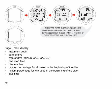
THERE ARE THREE PAGES OF LOGBOOK DIVE INFORMATION. USE SELECT BUTTON TO SCROLL BETWEEN LOGBOOK PAGES I, II, AND III. THE DATA OF
THE MOST RECENT DIVE IS SHOWN FIRST.
Page I, main display• maximum depth• date of dive• type of dive (MIXED GAS, GAUGE)• dive start time• dive number• oxygen percentage for Mix used in the beginning of the dive• helium percentage for Mix used in the beginning of the dive• dive time
82
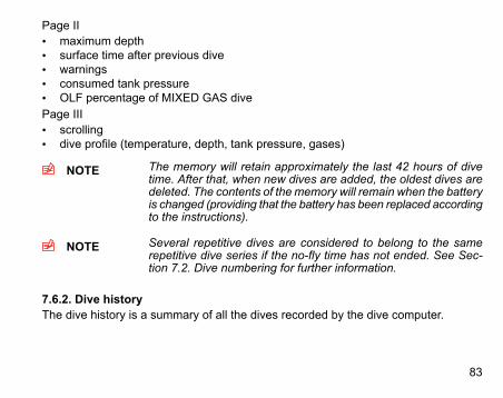
Page II• maximum depth• surface time after previous dive• warnings• consumed tank pressure• OLF percentage of MIXED GAS divePage III• scrolling• dive profile (temperature, depth, tank pressure, gases)
NOTE The memory will retain approximately the last 42 hours of divetime. After that, when new dives are added, the oldest dives aredeleted. The contents of the memory will remain when the batteryis changed (providing that the battery has been replaced accordingto the instructions).
NOTE Several repetitive dives are considered to belong to the samerepetitive dive series if the no-fly time has not ended. See Sec-tion 7.2. Dive numbering for further information.
7.6.2. Dive historyThe dive history is a summary of all the dives recorded by the dive computer.
83

DIVE HISTORY DISPLAY. TOTAL NUMBER OF DIVES, DIVE HOURS AND MAXIMUM DEPTH.
7.7. Suunto Dive Planner (SDP)Suunto Dive Planner is an essential part of your dive. It is used for creating dive plans.
WARNING Using the Suunto Dive Planner software is not a substitute forproper dive training. Diving with mixed gases has dangers thatare not familiar to divers diving with air. To dive with trimix, triox,heliox and nitrox or all of them, divers must have specializedtraining for the type of diving they are doing.
Start creating a dive plan by defining the maximum depth and bottom time. Next, plantravel, bottom and decompression gases. Based on the gases, the Dive Planner cal-culates the decompression schedule, gas change and decompression depths. Afterthe decompression schedule is ready, the needed gas volume for the dive is calculatedbased on the Surface Air Consumption (SAC) rate that can be checked from SuuntoDive Manager.
84
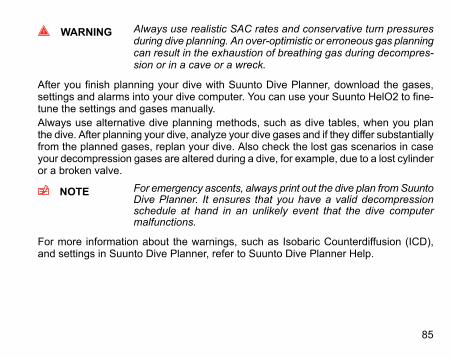
WARNING Always use realistic SAC rates and conservative turn pressuresduring dive planning. An over-optimistic or erroneous gas planningcan result in the exhaustion of breathing gas during decompres-sion or in a cave or a wreck.
After you finish planning your dive with Suunto Dive Planner, download the gases,settings and alarms into your dive computer. You can use your Suunto HelO2 to fine-tune the settings and gases manually.Always use alternative dive planning methods, such as dive tables, when you planthe dive. After planning your dive, analyze your dive gases and if they differ substantiallyfrom the planned gases, replan your dive. Also check the lost gas scenarios in caseyour decompression gases are altered during a dive, for example, due to a lost cylinderor a broken valve.
NOTE For emergency ascents, always print out the dive plan fromSuuntoDive Planner. It ensures that you have a valid decompressionschedule at hand in an unlikely event that the dive computermalfunctions.
For more information about the warnings, such as Isobaric Counterdiffusion (ICD),and settings in Suunto Dive Planner, refer to Suunto Dive Planner Help.
85

7.8. Suunto DM4 with MovescountThe Suunto DM4 with Movescount (DM4) is an optional software that greatly enhancesthe functionality of your Suunto . With the DM4 software, you can download dive datafrom your dive computer to your laptop. After that, you can view and organize all thedata recorded with your Suunto . You can plan dives (with Suunto Dive Planner), printcopies of your dive profiles, and also upload your dive logs to share with your friendsat http://www.movescount.com (see Section 7.9. Movescount). You can alwaysdownload the latest version of the DM4 from http://www.suunto.com. Please checkfor updates regularly as new features are constantly being developed. The followingdata is transferred from your dive computer to your laptop (optional, cable required):• depth profile of the dive• dive time• preceding surface interval time• dive number• dive start time (year, month, day, and time)• dive computer settings• oxygen percentage settings and maximum OLF (in the MIXED GAS mode)• tissue calculation data• real-time water temperature• tank pressure data (if enabled)• additional dive information (for example, SLOW and Mandatory Safety Stop viola-
tions, Diver Attention Symbol, Bookmark, Surfaced Mark, Decompression StopMark, and Ceiling Error Mark)
• dive computer serial number• personal information (30 characters)
86
By using the DM4, you are able to enter setup options such as:• input a personal, 30-character field into the Suunto instrument.• reset the Scuba History's maximum depth to zero• reset all Free Dive History• manually add comments, multimedia and other personal information to the PC-
based dive data files
7.9. MovescountMovescount is an online sports community that offers you a rich set of tools to manageall you sports and create engaging stories about your diving experiences. Movescountoffers you new ways to get inspired and share your best dives with other communitymembers!To connect to Movescount:1. Go to www.movescount.com.2. Register and create your free Movescount account.3. Download and install the Suunto DM4 with Movescount software from the
Movescount.com website if you do not already have the DM4 installed on yourlaptop
To transfer data:1. Connect your dive computer to your laptop.2. Download your dives to the DM4 on your laptop.3. Follow the instructions on the DM4 on how to transfer your dives to your
Movescount.com account.
87
8. CARE AND MAINTENANCE OF MY SUUNTO DIVING COM-PUTERThe SUUNTO dive computer is a sophisticated precision instrument. Although it isdesigned to withstand the rigors of scuba diving, you must treat it with the sameproper care and caution as any other precision instrument.• WATER CONTACTS AND PUSH BUTTONS
Contamination or dirt on the water contacts/connector or push buttons may preventthe automatic activation of the Dive Mode and cause problems during the datatransfer. Therefore, it is important that the water contacts and push buttons arekept clean. If the water contacts are active (AC text remains on display) or the DiveMode activates on its own, the reason for this is probably contamination or invisiblemarine growth, which may create an electric current between the contacts. It isimportant that the dive computer is carefully washed in fresh water after the day’sdiving is completed. The contacts can be cleaned with fresh water and, if necessary,a mild detergent and a soft brush. Sometimes it might be necessary to remove theinstrument from the protective boot for cleaning.
• CARE OF YOUR DIVE COMPUTERNEVER try to open the case of the dive computer.•
• Have your dive computer serviced every two years or after 200 dives (whichevercomes first) by an authorized dealer or distributor. This service will include ageneral operational check, replacement of the battery, and water resistancecheck. The service requires special tools and training. Therefore, it is advisableto contact an authorized SUUNTO dealer or distributor for service. Do not at-tempt to do any servicing that you are not sure of.
88

• Should moisture appear inside the case, immediately have the instrumentchecked by your SUUNTO dealer or distributor.
• Should you detect scratches, cracks or other such flaws on the display thatmay impair its durability, immediately have it replaced by your SUUNTO dealeror distributor.
• Wash and rinse the unit in fresh water after every use.• Protect the unit from shock, extreme heat, direct sunlight, and chemical attack.
The dive computer cannot withstand the impact of heavy objects like scubacylinders, nor chemicals like gasoline, cleaning solvents, aerosol sprays, adhes-ive agents, paint, acetone, alcohol, and so on. Chemical reactions with suchagents will damage the seals, case and finish.
• Store your dive computer in a dry place when you are not using it.• The dive computer will display a battery symbol as a warning when the power
gets too low. When this happens, the instrument should not be used until thebattery has been replaced.
• Do not fasten the strap of your dive computer too tightly. You should be ableto insert your finger between the strap and your wrist. Shorten the strap bycutting it if you do not expect to need the extra length.
89

• MAINTENANCEThe instrument should be soaked, thoroughly rinsed with fresh water, then driedwith a soft towel after each dive. Make sure that all salt crystals and sand particleshave been flushed out. Check the display for possible moisture or water. DO NOTuse the dive computer if you detect any moisture or water inside. Contact an au-thorized Suunto dealer for battery replacement or other service.CAUTION!• Do not use compressed air to blow water off the unit.• Do not use solvents or other cleaning fluids that might cause damage.• Do not test or use the dive computer in pressurized air.
• WATER RESISTANCE INSPECTIONThe water resistance of the unit must be checked after replacing the battery orafter other service operations. The check requires special equipment and training.You must frequently check the display for any sign of leaks. If you find moistureinside your dive computer, there is a leak. A leak must be corrected without delayas moisture will seriously damage the unit, even beyond repair. SUUNTO doesnot take any responsibility for damage caused by moisture in the dive computerunless the instructions of this manual are carefully followed. In the event of a leak,immediately take the dive computer to an authorized SUUNTO dealer or distributor.
FAQsFor more information on service, please refer to FAQs on www.suunto.com.
90
9. BATTERY REPLACEMENT
NOTE It is advisable to contact an authorized Suunto representative forbattery replacement. It is imperative that the change is made ina proper manner to avoid any leakage of water into the batterycompartment or computer.
CAUTION When the battery is changed, all nitrogen and oxygen uptake datais lost. Therefore, the no-fly time shown by the computer shouldhave reached zero or you must wait for 48 hours, or preferablyup to 100 hours, before you dive again.
All history and profile data, as well as the altitude, personal, and alarm settings, willremain in the dive computer memory after the battery change. However, the clocktime and time alarm settings are lost. In the MIXED GAS mode, the gas mix settingsalso revert back to default settings (Mix1 21% O2, 0% He, 1.4 bar PO2).
9.1. Battery kitThe battery kit includes a 3.0 V coin type lithium cell battery and a lubricated O ring.When handling the battery do not make contact with both of the poles at the sametime. Do not touch the surfaces of the battery with your bare fingers.
9.2. Required tools• A flat 1.5 mm screwdriver or a special tool for spring bars (K5857).• Soft cloth for cleaning.• Needlenose pliers or small screwdriver for turning securing ring.
91
9.3. Replacing the batteryThe battery and the buzzer are located in the back of the instrument in a separatecompartment. To change the battery:1. Thoroughly rinse and dry the computer.2. Open the securing ring of the battery compartment lid by pushing it down and
rotating it clockwise. You may use a pointed nose pliers or a small screwdriveras an aid in the rotating. Put the pliers ends into the holes of the securing ring orthe screwdriver onto the side of the right tooth on the ring and turn the ringclockwise. Be careful not to damage any of the parts.
3. Remove the ring.4. Carefully remove the lid with the beeper attached to it. You can remove the lid by
pressing with your finger on the outermost edge of the lid while simultaneouslypulling with your nail at the opposite side. Don't use sharp metal objects as theymight damage the O-ring or the sealing surfaces.
5. Remove the O-ring and the battery retainer.6. Carefully remove the battery. Do not damage the electrical contacts or the sealing
surface.7. Check for any traces of flooding, particularly between the beeper and the lid, or
for any other damage. In case of a leak or any other damage, bring the divecomputer to an authorized SUUNTO dealer or distributor for check and repair.
8. Check the condition of the O-ring; a defective O-ring may indicate sealing orother problems. Dispose the old O-ring, even if it seems to be in good condition.
9. Check that the battery compartment, battery holder and lid are clean. Clean withsoft cloth if necessary.
10. Reinstall the battery retainer in its correct position.
92
11. Check that the new lubricated O-ring is in good condition. Put it in the right positionon the battery compartment lid. Be very careful not to get any dirt on the o-ringor its sealing surfaces.
12. Carefully press the lid onto the battery compartment with your thumb, whilemaking sure that the O-ring is not at any point protruding out on the edge.
13. Put your other thumb through the locking ring. Press this thumb firmly against thelid and release the other one. Make sure that the lid is pressed completely down!
14. Turn the locking ring counterclockwise with your free thumb and fingers until itsnaps into its locked position.
15. The dive computer should now active its timekeeping mode and show time 18:00[6:00 PM] and date SA 01,01. Activate the instrument. Check that• all display segments work.• the low battery warning is off.• the buzzer beeps and backlight works.• all the settings are correct. Reset if necessary.
CAUTION Check after the first dives for possible moisture under the trans-parent battery compartment lid, indicating a leak.
93
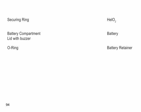
Securing Ring
Battery CompartmentLid with buzzer
O-Ring
HelO2
Battery
Battery Retainer
94

9.4. Wireless transmitter battery replacement
NOTE It is advisable to contact an authorized Suunto representative fortransmitter battery replacement. It is imperative that the changeis made in a proper manner to avoid any leakage of water intothe transmitter.
9.4.1. Transmitter battery kitThe transmitter battery kit includes a 3.0 V CR½AA lithium cell battery and a lubricatedO-ring. When handling the battery, do not make contact with both of the poles at thesame time. Do not touch the metal surfaces of the battery with your bare fingers.
95
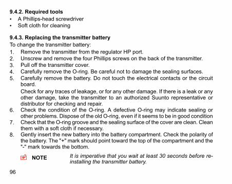
9.4.2. Required tools• A Phillips-head screwdriver• Soft cloth for cleaning
9.4.3. Replacing the transmitter batteryTo change the transmitter battery:1. Remove the transmitter from the regulator HP port.2. Unscrew and remove the four Phillips screws on the back of the transmitter.3. Pull off the transmitter cover.4. Carefully remove the O-ring. Be careful not to damage the sealing surfaces.5. Carefully remove the battery. Do not touch the electrical contacts or the circuit
board.Check for any traces of leakage, or for any other damage. If there is a leak or anyother damage, take the transmitter to an authorized Suunto representative ordistributor for checking and repair.
6. Check the condition of the O-ring. A defective O-ring may indicate sealing orother problems. Dispose of the old O-ring, even if it seems to be in good condition
7. Check that the O-ring groove and the sealing surface of the cover are clean. Cleanthem with a soft cloth if necessary.
8. Gently insert the new battery into the battery compartment. Check the polarity ofthe battery. The "+" mark should point toward the top of the compartment and the"-" mark towards the bottom.
NOTE It is imperative that you wait at least 30 seconds before re-installing the transmitter battery.
96
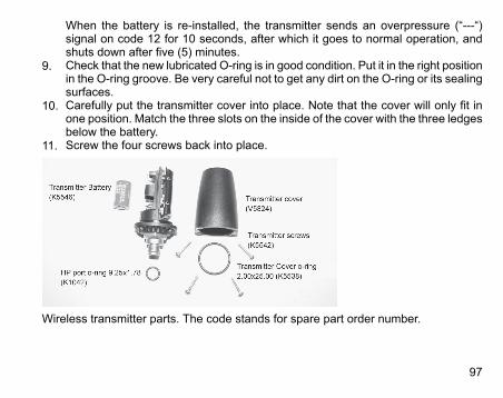
When the battery is re-installed, the transmitter sends an overpressure (“---“)signal on code 12 for 10 seconds, after which it goes to normal operation, andshuts down after five (5) minutes.
9. Check that the new lubricated O-ring is in good condition. Put it in the right positionin the O-ring groove. Be very careful not to get any dirt on the O-ring or its sealingsurfaces.
10. Carefully put the transmitter cover into place. Note that the cover will only fit inone position. Match the three slots on the inside of the cover with the three ledgesbelow the battery.
11. Screw the four screws back into place.
Wireless transmitter parts. The code stands for spare part order number.
97
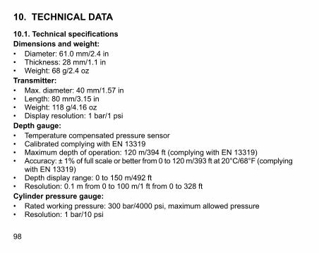
10. TECHNICAL DATA
10.1. Technical specificationsDimensions and weight:• Diameter: 61.0 mm/2.4 in• Thickness: 28 mm/1.1 in• Weight: 68 g/2.4 ozTransmitter:• Max. diameter: 40 mm/1.57 in• Length: 80 mm/3.15 in• Weight: 118 g/4.16 oz• Display resolution: 1 bar/1 psiDepth gauge:• Temperature compensated pressure sensor• Calibrated complying with EN 13319• Maximum depth of operation: 120 m/394 ft (complying with EN 13319)• Accuracy: ± 1% of full scale or better from 0 to 120m/393 ft at 20°C/68°F (complying
with EN 13319)• Depth display range: 0 to 150 m/492 ft• Resolution: 0.1 m from 0 to 100 m/1 ft from 0 to 328 ftCylinder pressure gauge:• Rated working pressure: 300 bar/4000 psi, maximum allowed pressure• Resolution: 1 bar/10 psi
98
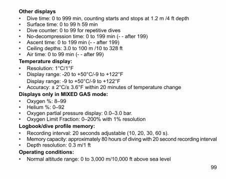
Other displays• Dive time: 0 to 999 min, counting starts and stops at 1.2 m /4 ft depth• Surface time: 0 to 99 h 59 min• Dive counter: 0 to 99 for repetitive dives• No-decompression time: 0 to 199 min (- - after 199)• Ascent time: 0 to 199 min (- - after 199)• Ceiling depths: 3.0 to 100 m /10 to 328 ft• Air time: 0 to 99 min (- - after 99)Temperature display:• Resolution: 1°C/1°F• Display range: -20 to +50°C/-9 to +122°F
Display range: -9 to +50°C/-9 to +122°F• Accuracy: ± 2°C/± 3.6°F within 20 minutes of temperature changeDisplays only in MIXED GAS mode:• Oxygen %: 8–99• Helium %: 0–92• Oxygen partial pressure display: 0.0–3.0 bar.• Oxygen Limit Fraction: 0–200% with 1% resolutionLogbook/dive profile memory:• Recording interval: 20 seconds adjustable (10, 20, 30, 60 s).• Memory capacity: approximately 80 hours of diving with 20 second recording interval• Depth resolution: 0.3 m/1 ftOperating conditions:• Normal altitude range: 0 to 3,000 m/10,000 ft above sea level
99
• Operating temperature: 0°C to 40°C/32°F to 104°F• Storage temperature: -20°C to +50°C/ -4°F to +122°FIt is recommended that the instrument be stored in a dry place at room temperature.
NOTE Do not leave the dive computer in direct sunlight!
Tissue calculation model:• Suunto RGBM algorithm (developed by Suunto and Bruce R. Wienke, BSc, MSc,
PhD)• 9 tissue compartments• Tissue compartment halftimes: 2.5, 5, 10, 20, 40, 80, 120, 240, and 480 minutes
(on gassing). The off gassing halftimes are slowed down• Helium halftimes:1, 2, 3.5, 7.5, 15, 30, 45, 90, 181 minutes (on gassing). The off
gassing halftimes are slowed down.• Reduced gradient (variable) "M" values based on diving habit and dive violations.
The "M" values are tracked up to 100 hours after a dive• The EAN and oxygen exposure calculations are based on recommendations by
R.W. Hamilton, PhD and currently accepted exposure time limit tables and prin-ciples.
Battery:• One 3 V lithium battery: CR 2450• Battery storage time (shelf life): Up to three years• Replacement: Every three years, or more often depending on dive activity• Life expectancy at 20°C/68°F:
• 100 dives/year –>1 year
100
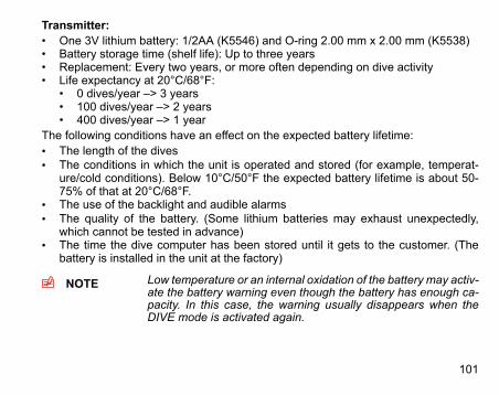
Transmitter:• One 3V lithium battery: 1/2AA (K5546) and O-ring 2.00 mm x 2.00 mm (K5538)• Battery storage time (shelf life): Up to three years• Replacement: Every two years, or more often depending on dive activity• Life expectancy at 20°C/68°F:
• 0 dives/year –> 3 years• 100 dives/year –> 2 years• 400 dives/year –> 1 year
The following conditions have an effect on the expected battery lifetime:• The length of the dives• The conditions in which the unit is operated and stored (for example, temperat-
ure/cold conditions). Below 10°C/50°F the expected battery lifetime is about 50-75% of that at 20°C/68°F.
• The use of the backlight and audible alarms• The quality of the battery. (Some lithium batteries may exhaust unexpectedly,
which cannot be tested in advance)• The time the dive computer has been stored until it gets to the customer. (The
battery is installed in the unit at the factory)
NOTE Low temperature or an internal oxidation of the battery may activ-ate the battery warning even though the battery has enough ca-pacity. In this case, the warning usually disappears when theDIVE mode is activated again.
101
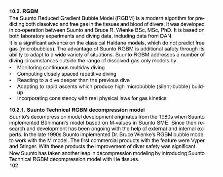
10.2. RGBMThe Suunto Reduced Gradient Bubble Model (RGBM) is a modern algorithm for pre-dicting both dissolved and free gas in the tissues and blood of divers. It was developedin co-operation between Suunto and Bruce R. Wienke BSc, MSc, PhD. It is based onboth laboratory experiments and diving data, including data from DAN.It is a significant advance on the classical Haldane models, which do not predict freegas (microbubbles). The advantage of Suunto RGBM is additional safety through itsability to adapt to a wide variety of situations. Suunto RGBM addresses a number ofdiving circumstances outside the range of dissolved-gas-only models by:• Monitoring continuous multiday diving• Computing closely spaced repetitive diving• Reacting to a dive deeper than the previous dive• Adapting to rapid ascents which produce high microbubble (silent-bubble) build-
up• Incorporating consistency with real physical laws for gas kinetics
10.2.1. Suunto Technical RGBM decompression modelSuunto's decompression model development originates from the 1980s when Suuntoimplemented Bühlmann's model based on M-values in Suunto SME. Since then re-search and development has been ongoing with the help of external and internal ex-perts. In the late 1990s Suunto implemented Dr. BruceWienke's RGBM bubble modelto work with the M model. The first commercial products with the feature were Vyperand Stinger. With these products the improvement of diver safety was significant.Now Suunto has taken another leap in decompression modeling by introducing SuuntoTechnical RGBM decompression model with He tissues.102
Suunto Technical RGBMmodel is a modified version of the M-value model. Calculationof the M-value model can be found in common dive literature. Modifications have beenmade to have the model follow RGBM theory as closely as possible. The modificationshave been conducted with the help of Dr. Bruce Wienke. Functionality of SuuntoTechnical RGBM has been validated and verified to the depth of 120 m/393 ft withhundreds of test dives both in the field and in laboratory. The algorithm should not beused in deeper depths than the verified depth.Suunto technical algorithm models the human body by using nine tissue groups. Intheory the model is accurate if there are more tissue groups, but using more than ninetissue groups has no practical significance.Tissue calculation aims to model the amount of nitrogen (N2) and helium (He) saturatedin tissues. Ongasing and offgasing of saturated gas is modelled using the ideal gasequation. In practice this means that the total pressure of the nitrogen and helium tis-sues can be higher than the total pressure of the breathing gas, even without any ex-posure to pressure. For example, when a diver dives an air dive soon after a demandingtrimix dive, the residual pressure of helium combined with a high nitrogen contentcause the diver a decompression obligation very fast.
103
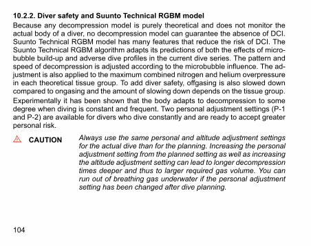
10.2.2. Diver safety and Suunto Technical RGBM modelBecause any decompression model is purely theoretical and does not monitor theactual body of a diver, no decompression model can guarantee the absence of DCI.Suunto Technical RGBM model has many features that reduce the risk of DCI. TheSuunto Technical RGBM algorithm adapts its predictions of both the effects of micro-bubble build-up and adverse dive profiles in the current dive series. The pattern andspeed of decompression is adjusted according to the microbubble influence. The ad-justment is also applied to the maximum combined nitrogen and helium overpressurein each theoretical tissue group. To add diver safety, offgasing is also slowed downcompared to ongasing and the amount of slowing down depends on the tissue group.Experimentally it has been shown that the body adapts to decompression to somedegree when diving is constant and frequent. Two personal adjustment settings (P-1and P-2) are available for divers who dive constantly and are ready to accept greaterpersonal risk.
CAUTION Always use the same personal and altitude adjustment settingsfor the actual dive than for the planning. Increasing the personaladjustment setting from the planned setting as well as increasingthe altitude adjustment setting can lead to longer decompressiontimes deeper and thus to larger required gas volume. You canrun out of breathing gas underwater if the personal adjustmentsetting has been changed after dive planning.
104
10.2.3. Altitude divingThe atmospheric pressure is lower at high altitudes than at sea level. After travelingto a higher altitude, you will have additional nitrogen in your body, compared to theequilibrium situation at the original altitude. This "additional" nitrogen is releasedgradually over time and equilibrium is restored. It is recommended that you acclimatizeto a new altitude by waiting at least three hours before making a dive.Before high-altitude diving, the instrument must be set to the Altitude Adjustment modeto adjust the calculations for the new altitude. The maximum partial pressures of nitro-gen allowed by the mathematical model of the dive computer are reduced accordingto the lower ambient pressure.As a result, the allowed no-decompression-stop limits are considerably reduced.
10.3. Oxygen exposureThe oxygen exposure calculations are based on currently accepted exposure timelimit tables and principles. In addition to this, the dive computer uses several methodsto conservatively estimate the oxygen exposure. For example:• The displayed oxygen exposure calculations are raised to the next higher percent-
age value.• The CNS % limits up to1.6 bar are based on 1991 NOAA Diving Manual limits• The OTUmonitoring is based on the long-term daily tolerance level and the recovery
rate is reduced.Oxygen related information displayed by the dive computer is also designed to ensurethat all warnings and displays occur at the appropriate phases of a dive. For example,the following information will be shown before and during a dive when the computeris set in mode:
105

• The selected O2% on the alternative display• OLF% alternative display for either CNS% or OTU% (whichever is larger)• Audible alarms are given and the OLF value starts to blink when the 80% and
100% limits are exceeded.• Audible alarms are given and the actual PO2 value blinks when it exceeds the
preset limit.• In dive planning, the maximum depth according to the O2% and maximum PO2
selected.
106
11. INTELLECTUAL PROPERTY
11.1. TrademarkSuunto is a registered trademark of Suunto Oy.
11.2. Copyright© Suunto Oy 08/2011. All rights reserved.
11.3. Patent noticePatents have been issued or applied for one or several features of this product.
107
12. DISCLAIMERS
12.1. CEThe CE mark is used to mark conformity with the European Union EMC directive89/336/EEC.
12.2. EN 13319EN 13319 is a European diving depth gauge standard. Suunto dive computers aredesigned to comply with this standard.
12.3. EN 250 / FIOHThe tank pressure gauge and dive instrument parts used inmeasuring the tank pressuremeet the requirements set in the section of the European Standard EN 250 that concerntank pressure measurements. FIOH, notified body no.0430, has EC type-examinedthis type of personal protective equipment.
108
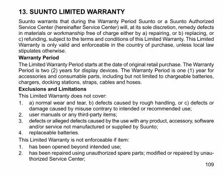
13. SUUNTO LIMITED WARRANTYSuunto warrants that during the Warranty Period Suunto or a Suunto AuthorizedService Center (hereinafter Service Center) will, at its sole discretion, remedy defectsin materials or workmanship free of charge either by a) repairing, or b) replacing, orc) refunding, subject to the terms and conditions of this Limited Warranty. This LimitedWarranty is only valid and enforceable in the country of purchase, unless local lawstipulates otherwise.Warranty PeriodThe LimitedWarranty Period starts at the date of original retail purchase. TheWarrantyPeriod is two (2) years for display devices. The Warranty Period is one (1) year foraccessories and consumable parts, including but not limited to chargeable batteries,chargers, docking stations, straps, cables and hoses.Exclusions and LimitationsThis Limited Warranty does not cover:1. a) normal wear and tear, b) defects caused by rough handling, or c) defects or
damage caused by misuse contrary to intended or recommended use;2. user manuals or any third-party items;3. defects or alleged defects caused by the use with any product, accessory, software
and/or service not manufactured or supplied by Suunto;4. replaceable batteries.This Limited Warranty is not enforceable if item:1. has been opened beyond intended use;2. has been repaired using unauthorized spare parts; modified or repaired by unau-
thorized Service Center;109
3. serial number has been removed, altered or made illegible in any way, as determ-ined at the sole discretion of Suunto;
4. has been exposed to chemicals including but not limited to mosquito repellents.Suunto does not warrant that the operation of the Product will be uninterrupted or errorfree, or that the Product will work in combination with any hardware or software providedby a third party.Access to Suunto warranty serviceRegister your item at www.suunto.com/register and save the purchase receipt and/orregistration card. For instructions how to obtain warranty service, visit www.suunto.com,contact your local authorized Suunto retailer, or call Suunto Help Desk +358 2 2841160(national or premium rates may apply).Limitation of LiabilityTo the maximum extent permitted by applicable mandatory laws, this LimitedWarrantyis your sole and exclusive remedy and is in lieu of all other warranties, expressed orimplied. Suunto shall not be liable for special, incidental, punitive or consequentialdamages, including but not limited to loss of anticipated benefits, loss of data, loss ofuse, cost of capital, cost of any substitute equipment or facilities, claims of third parties,damage to property resulting from the purchase or use of the item or arising frombreach of the warranty, breach of contract, negligence, strict tort, or any legal orequitable theory, even if Suunto knew of the likelihood of such damages. Suunto shallnot be liable for delay in rendering warranty service.
110
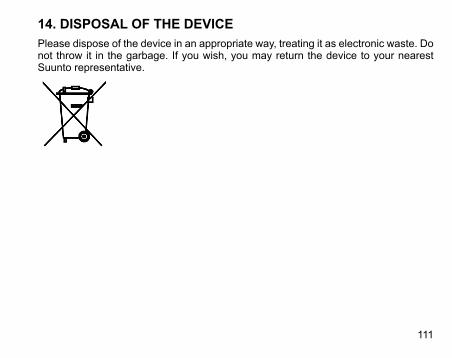
14. DISPOSAL OF THE DEVICEPlease dispose of the device in an appropriate way, treating it as electronic waste. Donot throw it in the garbage. If you wish, you may return the device to your nearestSuunto representative.
111
GLOSSARYAltitude dive A dive made at an elevation greater than 300 m/1000 ft above sea level.Ascent rate The speed at which the diver ascends toward the surface.ASC RATE Abbreviation for ascent rate.Ascent time The minimum amount of time needed to reach the surface on a decom-
pression stop dive.ASC TIME Abbreviation for ascent time.Ceiling On a decompression stop dive, the shallowest depth to which a diver may
ascend based on computed nitrogen load.Central nervous system toxicity Toxicity caused by oxygen. Can cause a variety of neurological symptoms.
The most important of which is an epileptic-like convulsion which cancause a diver to drown.
CNS Abbreviation for central nervous system toxicity.CNS% Central nervous system toxicity limit fraction. Also note Oxygen Limit
FractionCompartment See "Tissue group".DAN Abbreviation for Divers Alert Network.DCI Abbreviation for decompression illness.DM4 Suunto DM4 with Movescount, a software for managing your divesDecompression Time spent at a decompression stop, or range, before surfacing, to allow
absorbed nitrogen to escape naturally from tissuesDecompression range On a decompression stop dive, the depth range between the floor and
the ceiling within which a diver must stop for some time during ascent.112

Decompression illness Any of a variety of maladies resulting either directly or indirectly from theformation of nitrogen bubbles in tissues or body fluids, as a result of inad-equately controlled decompression. Commonly called "the bends" or"DCI".
Dive series A group of repetitive dives between which the dive computer indicatessome nitrogen loading is present. When nitrogen loading reaches zerothe dive computer deactivates.
Dive time Elapsed time between leaving the surface to descend, and returning tothe surface at the end of a dive.
EAD Abbreviation for equivalent air depth.EAN Abbreviation for enriched air nitrox.Enriched air nitrox Also called nitrox or Enriched Air = EANx. Air that has some oxygen ad-
ded. Standard mixes are EAN32 (NOAA Nitrox I = NN I) and EAN36(NOAA Nitrox II = NN II).
Equivalent air depth Nitrogen partial pressure equivalent table.Floor The deepest depth during a decompression stop dive at which decom-
pression takes place.Half time After a change in ambient pressure, the amount of time required for the
partial pressure of nitrogen in a theoretical compartment to go half wayfrom its previous value to saturation at the new ambient pressure.
He% Helium percentage or helium fraction in the breathing gas.Heliox A breathing gas mix of helium and oxygen.MOD The maximum operating depth of a breathing gas is the depth at which
the partial pressure of oxygen (PO2) of the gas mix exceeds a safe limit.
113

Multi level dive A single or repetitive dive that includes time spent at various depths andwhose no decompression limits are therefore not determined solely bythe maximum depth attained.
Nitrox In sports diving, refers to any mix with a higher fraction of oxygen thanstandard air.
NOAA United States National Oceanic and Atmospheric Administration.No decompression time The maximum amount of time a diver may remain at a particular depth
without having to make decompression stops during the subsequent as-cent.
No decompression dive Any dive which permits a direct, uninterrupted ascent to the surface atany time.
NO DEC TIME Abbreviation for no decompression time limit.OEA = EAN = EANx Abbreviations for oxygen enriched air nitrox.OLF Abbreviation for oxygen limit fraction.OTU Abbreviation for oxygen tolerance unit.Oxygen tolerance unit Used to measure the whole-body-toxicity.Oxygen limit fraction A term used by Suunto for the values displayed in the oxygen toxicity bar
graph. The value is either the CNS% or the OTU%.O2% Oxygen percentage or oxygen fraction in the breathing gas. Standard air
has 21% oxygen.Oxygen partial pressure Limits the maximum depth to which the nitrox mixture can be safely used.
The maximum partial pressure limit for enriched air diving is 1.4 bar. Thecontingency partial pressure limit is 1.6 bar. Dives beyond this limit riskimmediate oxygen toxicity.
114
PFO Abbreviation for patent foramen ovale. It is a form of congenital heartdefect that enables blood flow between the left and right atria via the in-teratrial septum.
PO2 Abbreviation for oxygen partial pressure.RGBM Abbreviation for Reduced Gradient Bubble Model.Reduced Gradient Bubble Model Modern algorithm for tracking both dissolved and free gas in divers.Repetitive dive Any dive whose decompression time limits are affected by residual nitro-
gen absorbed during previous dives.Residual nitrogen The amount of excess nitrogen remaining in a diver after one or more
dives.SURF TIME Abbreviation for surface interval time.Surface interval time Elapsed time between surfacing from a dive and beginning a descent for
the subsequent repetitive dive.Technical dive A dive made with two or more breathing gas mixes.Tissue group Theoretical concept used to model bodily tissues for the construction of
decompression tables or calculations.Trimix A breathing gas mix of helium, oxygen and nitrogen.UHMS Abbreviation for Undersea and Hyperbaric Medical Society.Whole-body toxicity Another form of oxygen toxicity, which is caused by prolonged exposure
to high oxygen partial pressures. The most common symptoms are irrita-tion in the lungs, a burning sensation in the chest, coughing and reductionof the vital capacity. Also called Pulmonary Oxygen Toxicity. See alsoOTU.
115

SUUNTO HELP DESKGlobal +358 2 284 1160USA (toll free) +1-800-543-9124Canada (toll free) +1-800-267-7506
www.suunto.com
Copyright © Suunto Oy 04/2009, 08/2011.Suunto is a registered trademark of Suunto Oy.All Rights reserved.