Embed Size (px)
Citation preview
8/8/2019 Helicopter Fundamentals
http://slidepdf.com/reader/full/helicopter-fundamentals 1/66
Helicopter Aviation
op] [Up] [Prev] [Next]
Rotary Wing Planform
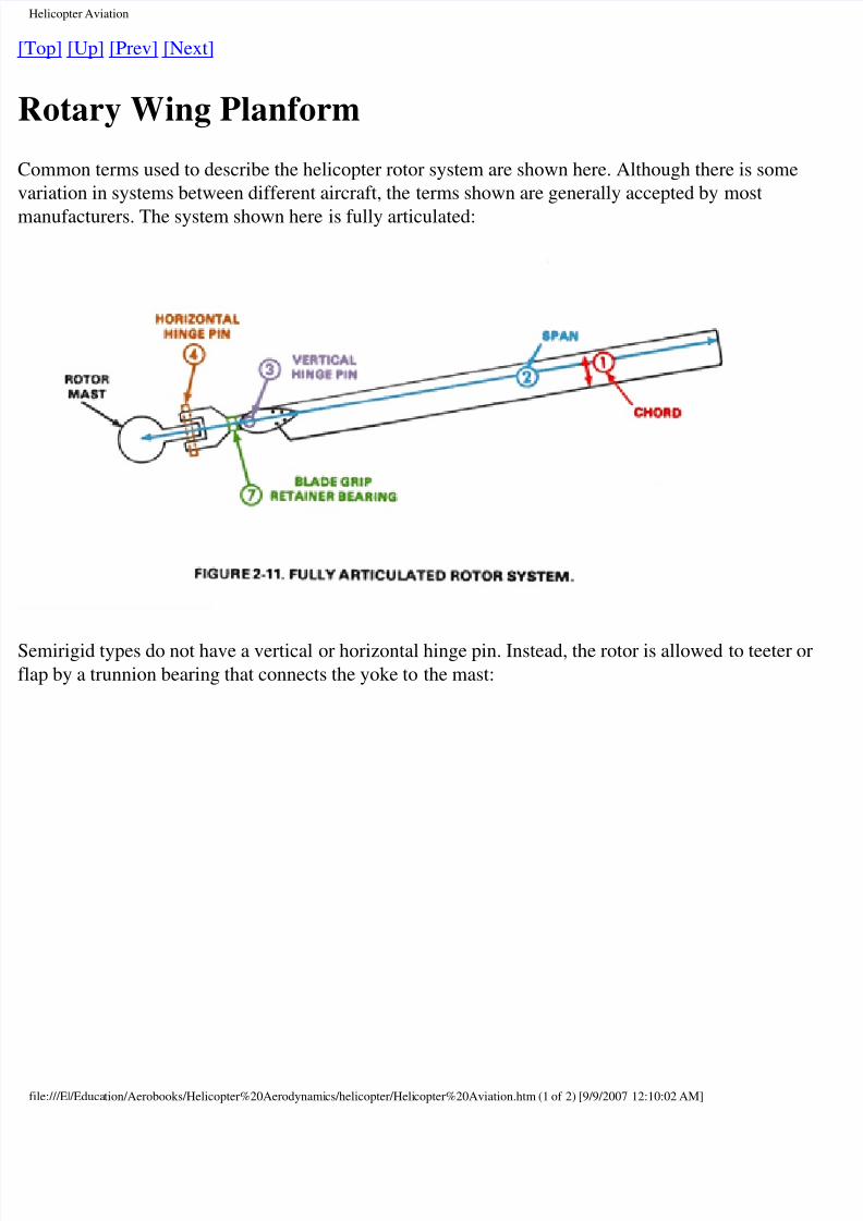
ommon terms used to describe the helicopter rotor system are shown here. Although there is some
riation in systems between different aircraft, the terms shown are generally accepted by most
anufacturers. The system shown here is fully articulated:
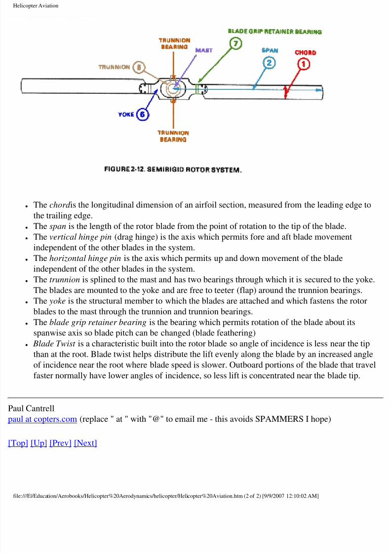
emirigid types do not have a vertical or horizontal hinge pin. Instead, the rotor is allowed to teeter o
ap by a trunnion bearing that connects the yoke to the mast:
le:///E|/Education/Aerobooks/Helicopter%20Aerodynamics/helicopter/Helicopter%20Aviation.htm (1 of 2) [9/9/2007 12:10:02 AM]
8/8/2019 Helicopter Fundamentals
http://slidepdf.com/reader/full/helicopter-fundamentals 2/66
Helicopter Aviation
● The chord is the longitudinal dimension of an airfoil section, measured from the leading edge
the trailing edge.
● The span is the length of the rotor blade from the point of rotation to the tip of the blade.
● The vertical hinge pin (drag hinge) is the axis which permits fore and aft blade movement
independent of the other blades in the system.
● The horizontal hinge pin is the axis which permits up and down movement of the blade
independent of the other blades in the system.
● The trunnion is splined to the mast and has two bearings through which it is secured to the yo
The blades are mounted to the yoke and are free to teeter (flap) around the trunnion bearings.● The yoke is the structural member to which the blades are attached and which fastens the roto
blades to the mast through the trunnion and trunnion bearings.
● The blade grip retainer bearing is the bearing which permits rotation of the blade about its
spanwise axis so blade pitch can be changed (blade feathering)
● Blade Twist is a characteristic built into the rotor blade so angle of incidence is less near the ti
than at the root. Blade twist helps distribute the lift evenly along the blade by an increased ang
of incidence near the root where blade speed is slower. Outboard portions of the blade that tra
faster normally have lower angles of incidence, so less lift is concentrated near the blade tip.
aul Cantrell
ul at copters.com (replace " at " with "@" to email me - this avoids SPAMMERS I hope)
op] [Up] [Prev] [Next]
le:///E|/Education/Aerobooks/Helicopter%20Aerodynamics/helicopter/Helicopter%20Aviation.htm (2 of 2) [9/9/2007 12:10:02 AM]
8/8/2019 Helicopter Fundamentals
http://slidepdf.com/reader/full/helicopter-fundamentals 3/66
Helicopter Aviation
op] [Up] [Prev] [Next]
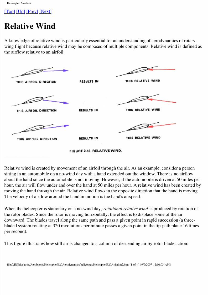
Relative Wind
knowledge of relative wind is particularly essential for an understanding of aerodynamics of rotary
ing flight because relative wind may be composed of multiple components. Relative wind is define
e airflow relative to an airfoil:
elative wind is created by movement of an airfoil through the air. As an example, consider a person
ting in an automobile on a no-wind day with a hand extended out the window. There is no airflow
out the hand since the automobile is not moving. However, if the automobile is driven at 50 miles
our, the air will flow under and over the hand at 50 miles per hour. A relative wind has been created
oving the hand through the air. Relative wind flows in the opposite direction that the hand is movin
he velocity of airflow around the hand in motion is the hand's airspeed.
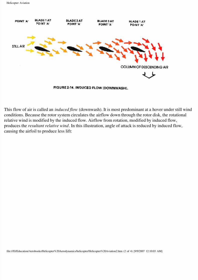
hen the helicopter is stationary on a no-wind day, rotational relative wind is produced by rotation o
e rotor blades. Since the rotor is moving horizontally, the effect is to displace some of the air
ownward. The blades travel along the same path and pass a given point in rapid succession (a three-
aded system rotating at 320 revolutions per minute passes a given point in the tip-path plane 16 tim
r second).
his figure illustrates how still air is changed to a column of descending air by rotor blade action:
le:///E|/Education/Aerobooks/Helicopter%20Aerodynamics/helicopter/Helicopter%20Aviation2.htm (1 of 4) [9/9/2007 12:10:03 AM]
8/8/2019 Helicopter Fundamentals
http://slidepdf.com/reader/full/helicopter-fundamentals 4/66
Helicopter Aviation
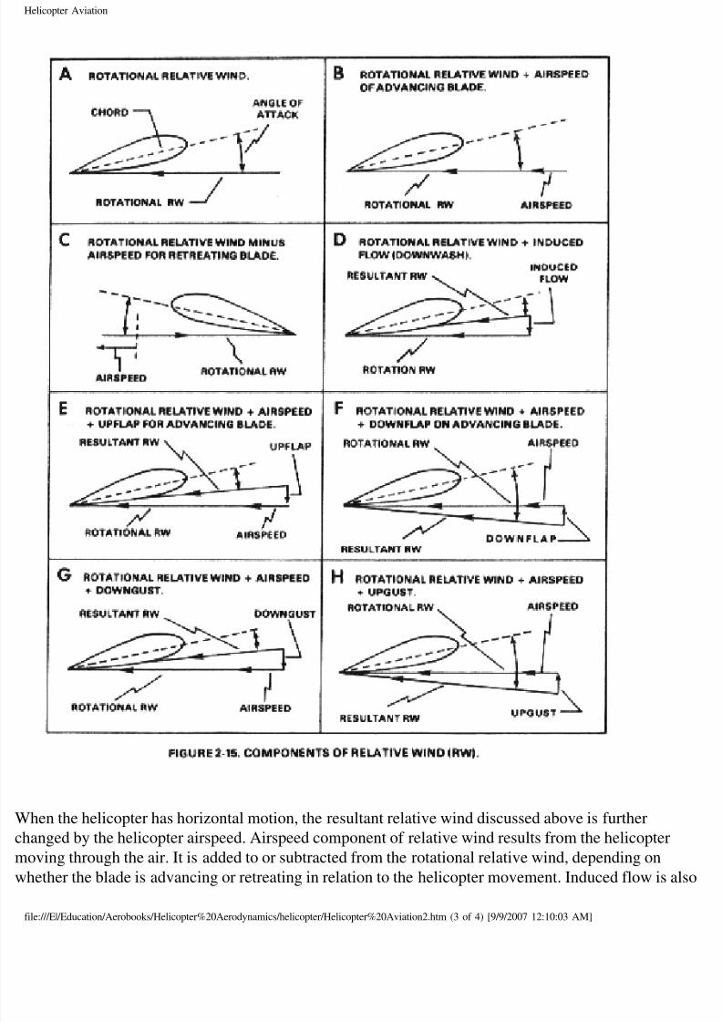
his flow of air is called an induced flow (downwash). It is most predominant at a hover under still w
nditions. Because the rotor system circulates the airflow down through the rotor disk, the rotationa
lative wind is modified by the induced flow. Airflow from rotation, modified by induced flow,
oduces the resultant relative wind . In this illustration, angle of attack is reduced by induced flow,
using the airfoil to produce less lift:
le:///E|/Education/Aerobooks/Helicopter%20Aerodynamics/helicopter/Helicopter%20Aviation2.htm (2 of 4) [9/9/2007 12:10:03 AM]
8/8/2019 Helicopter Fundamentals
http://slidepdf.com/reader/full/helicopter-fundamentals 5/66
Helicopter Aviation
hen the helicopter has horizontal motion, the resultant relative wind discussed above is further
anged by the helicopter airspeed. Airspeed component of relative wind results from the helicopter
oving through the air. It is added to or subtracted from the rotational relative wind, depending on
hether the blade is advancing or retreating in relation to the helicopter movement. Induced flow is a
le:///E|/Education/Aerobooks/Helicopter%20Aerodynamics/helicopter/Helicopter%20Aviation2.htm (3 of 4) [9/9/2007 12:10:03 AM]
8/8/2019 Helicopter Fundamentals
http://slidepdf.com/reader/full/helicopter-fundamentals 6/66
Helicopter Aviation
odified by introduction of airspeed relative wind. The pattern of air circulation through the disk
anges when the aircraft has movement. Generally the downward velocity of induced flow is reduce
he helicopter moves continually into an undisturbed airmass, resulting in less time to develop a vert
rflow pattern. As a result, additional lift is produced from a given blade pitch setting.
aul Cantrell
ul at copters.com (replace " at " with "@" to email me - this avoids SPAMMERS I hope)
op] [Up] [Prev] [Next]
le:///E|/Education/Aerobooks/Helicopter%20Aerodynamics/helicopter/Helicopter%20Aviation2.htm (4 of 4) [9/9/2007 12:10:03 AM]
8/8/2019 Helicopter Fundamentals
http://slidepdf.com/reader/full/helicopter-fundamentals 7/66
Helicopter Aviation
op] [Up] [Prev] [Next]
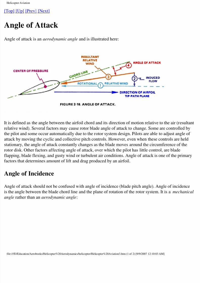
Angle of Attack
ngle of attack is an aerodynamic angle and is illustrated here:
is defined as the angle between the airfoil chord and its direction of motion relative to the air (resu
lative wind). Several factors may cause rotor blade angle of attack to change. Some are controlled b
e pilot and some occur automatically due to the rotor system design. Pilots are able to adjust angle
tack by moving the cyclic and collective pitch controls. However, even when these controls are hel
ationary, the angle of attack constantly changes as the blade moves around the circumference of the
tor disk. Other factors affecting angle of attack, over which the pilot has little control, are bladeapping, blade flexing, and gusty wind or turbulent air conditions. Angle of attack is one of the prim
ctors that determines amount of lift and drag produced by an airfoil.
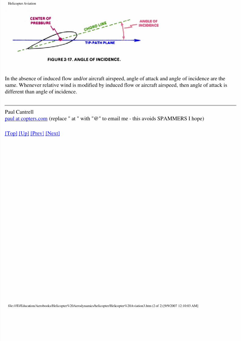
ngle of Incidence
ngle of attack should not be confused with angle of incidence (blade pitch angle). Angle of inciden
the angle between the blade chord line and the plane of rotation of the rotor system. It is a mechan
ngle rather than an aerodynamic angle:
le:///E|/Education/Aerobooks/Helicopter%20Aerodynamics/helicopter/Helicopter%20Aviation3.htm (1 of 2) [9/9/2007 12:10:03 AM]
8/8/2019 Helicopter Fundamentals
http://slidepdf.com/reader/full/helicopter-fundamentals 8/66
Helicopter Aviation
the absence of induced flow and/or aircraft airspeed, angle of attack and angle of incidence are the
me. Whenever relative wind is modified by induced flow or aircraft airspeed, then angle of attack i
fferent than angle of incidence.
aul Cantrell
ul at copters.com (replace " at " with "@" to email me - this avoids SPAMMERS I hope)
op] [Up] [Prev] [Next]
le:///E|/Education/Aerobooks/Helicopter%20Aerodynamics/helicopter/Helicopter%20Aviation3.htm (2 of 2) [9/9/2007 12:10:03 AM]
8/8/2019 Helicopter Fundamentals
http://slidepdf.com/reader/full/helicopter-fundamentals 9/66
Helicopter Aviation
op] [Up] [Prev] [Next]
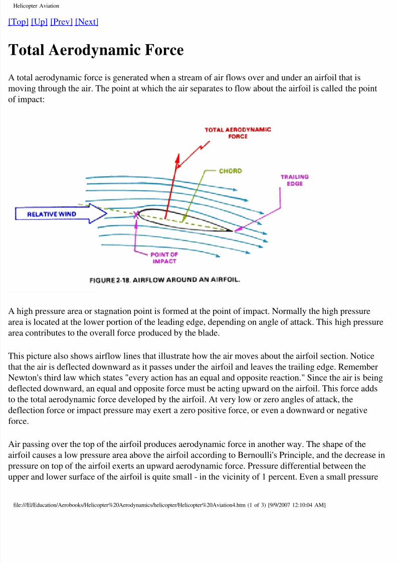
Total Aerodynamic Force
total aerodynamic force is generated when a stream of air flows over and under an airfoil that is
oving through the air. The point at which the air separates to flow about the airfoil is called the poi
impact:
high pressure area or stagnation point is formed at the point of impact. Normally the high pressure
ea is located at the lower portion of the leading edge, depending on angle of attack. This high press
ea contributes to the overall force produced by the blade.
his picture also shows airflow lines that illustrate how the air moves about the airfoil section. Notic
at the air is deflected downward as it passes under the airfoil and leaves the trailing edge. Rememb
ewton's third law which states "every action has an equal and opposite reaction." Since the air is be
flected downward, an equal and opposite force must be acting upward on the airfoil. This force add
the total aerodynamic force developed by the airfoil. At very low or zero angles of attack, the
flection force or impact pressure may exert a zero positive force, or even a downward or negative
rce.
ir passing over the top of the airfoil produces aerodynamic force in another way. The shape of the
rfoil causes a low pressure area above the airfoil according to Bernoulli's Principle, and the decreas
essure on top of the airfoil exerts an upward aerodynamic force. Pressure differential between the
pper and lower surface of the airfoil is quite small - in the vicinity of 1 percent. Even a small pressu
le:///E|/Education/Aerobooks/Helicopter%20Aerodynamics/helicopter/Helicopter%20Aviation4.htm (1 of 3) [9/9/2007 12:10:04 AM]
8/8/2019 Helicopter Fundamentals
http://slidepdf.com/reader/full/helicopter-fundamentals 10/66
Helicopter Aviation
fferential produces substantial force when applied to the large area of a rotor blade.
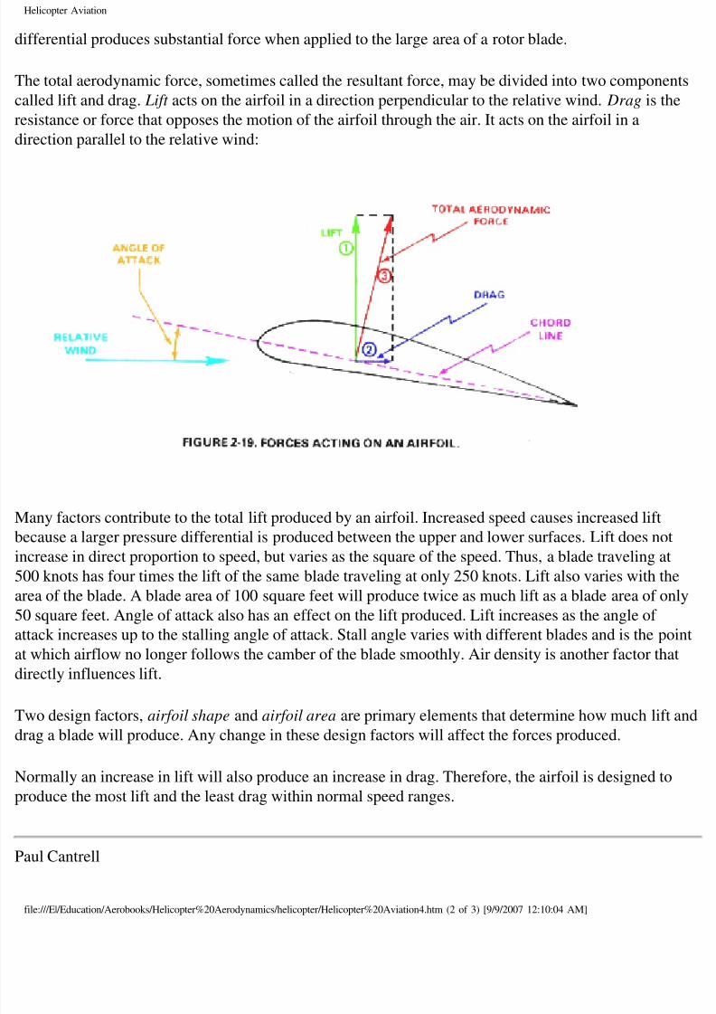
he total aerodynamic force, sometimes called the resultant force, may be divided into two compone
lled lift and drag. Lift acts on the airfoil in a direction perpendicular to the relative wind. Drag is th
sistance or force that opposes the motion of the airfoil through the air. It acts on the airfoil in a
rection parallel to the relative wind:
any factors contribute to the total lift produced by an airfoil. Increased speed causes increased lift
cause a larger pressure differential is produced between the upper and lower surfaces. Lift does nocrease in direct proportion to speed, but varies as the square of the speed. Thus, a blade traveling at
00 knots has four times the lift of the same blade traveling at only 250 knots. Lift also varies with th
ea of the blade. A blade area of 100 square feet will produce twice as much lift as a blade area of o
0 square feet. Angle of attack also has an effect on the lift produced. Lift increases as the angle of
tack increases up to the stalling angle of attack. Stall angle varies with different blades and is the po
which airflow no longer follows the camber of the blade smoothly. Air density is another factor th
rectly influences lift.
wo design factors, airfoil shape and airfoil area are primary elements that determine how much liftag a blade will produce. Any change in these design factors will affect the forces produced.
ormally an increase in lift will also produce an increase in drag. Therefore, the airfoil is designed to
oduce the most lift and the least drag within normal speed ranges.
aul Cantrell
le:///E|/Education/Aerobooks/Helicopter%20Aerodynamics/helicopter/Helicopter%20Aviation4.htm (2 of 3) [9/9/2007 12:10:04 AM]

8/8/2019 Helicopter Fundamentals
http://slidepdf.com/reader/full/helicopter-fundamentals 11/66
Helicopter Aviation
ul at copters.com (replace " at " with "@" to email me - this avoids SPAMMERS I hope)
op] [Up] [Prev] [Next]
le:///E|/Education/Aerobooks/Helicopter%20Aerodynamics/helicopter/Helicopter%20Aviation4.htm (3 of 3) [9/9/2007 12:10:04 AM]
8/8/2019 Helicopter Fundamentals
http://slidepdf.com/reader/full/helicopter-fundamentals 12/66
Helicopter Aviation
op] [Up] [Prev] [Next]
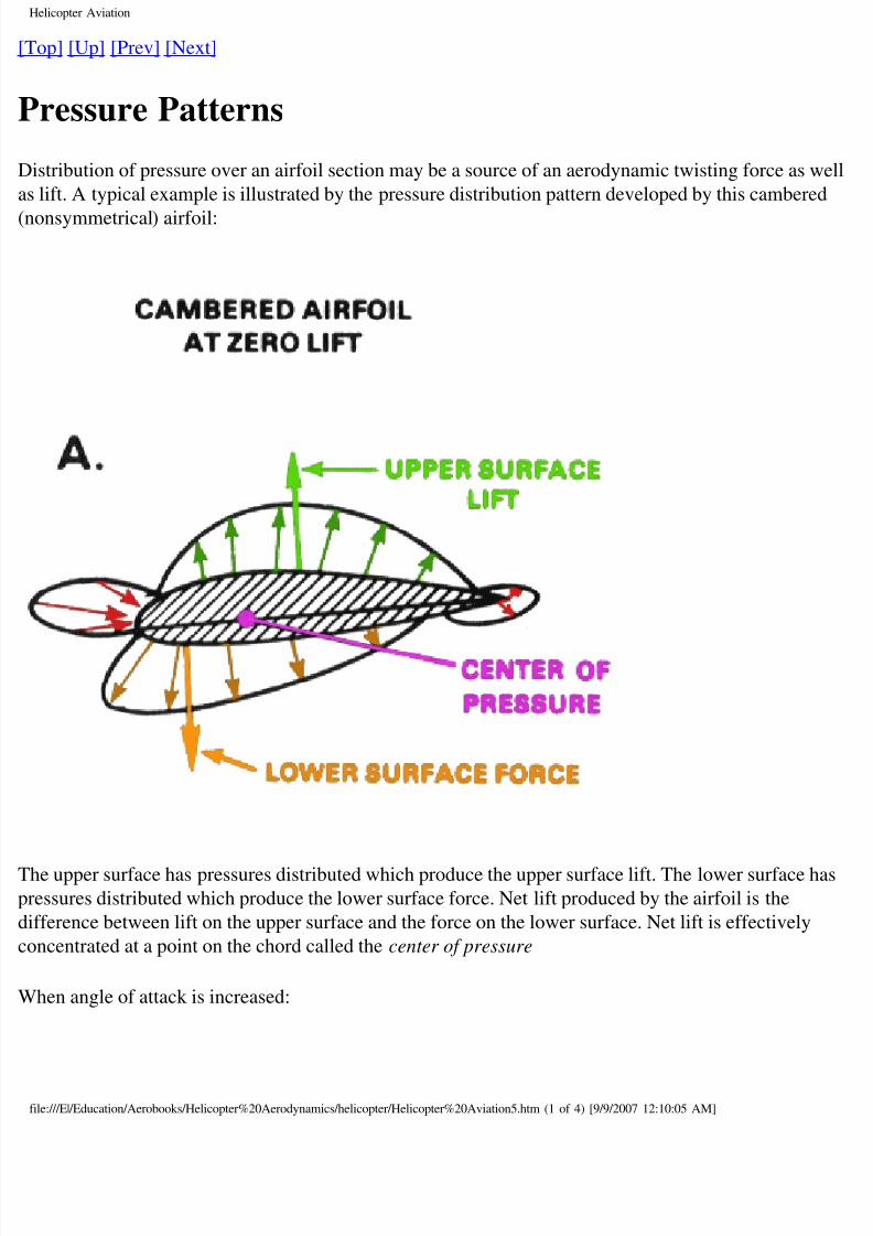
Pressure Patterns
istribution of pressure over an airfoil section may be a source of an aerodynamic twisting force as w
lift. A typical example is illustrated by the pressure distribution pattern developed by this cambere
onsymmetrical) airfoil:
he upper surface has pressures distributed which produce the upper surface lift. The lower surface h
essures distributed which produce the lower surface force. Net lift produced by the airfoil is the
fference between lift on the upper surface and the force on the lower surface. Net lift is effectively
ncentrated at a point on the chord called the center of pressure
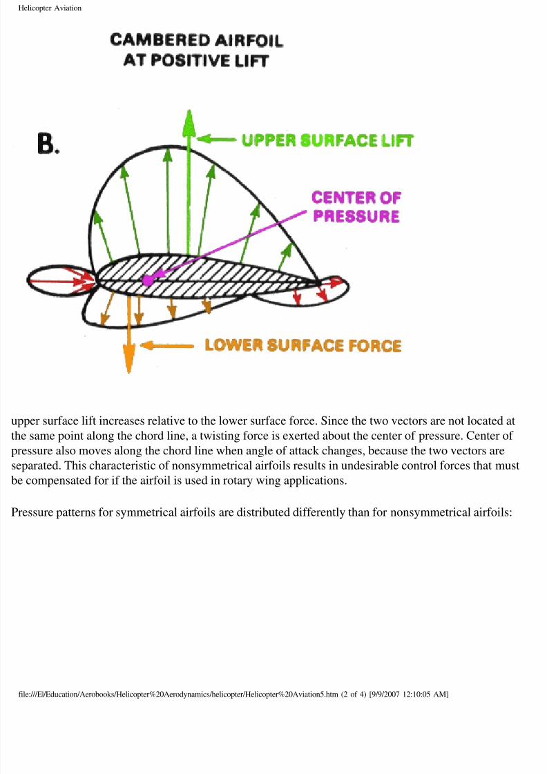
hen angle of attack is increased:
le:///E|/Education/Aerobooks/Helicopter%20Aerodynamics/helicopter/Helicopter%20Aviation5.htm (1 of 4) [9/9/2007 12:10:05 AM]
8/8/2019 Helicopter Fundamentals
http://slidepdf.com/reader/full/helicopter-fundamentals 13/66
Helicopter Aviation
pper surface lift increases relative to the lower surface force. Since the two vectors are not located a
e same point along the chord line, a twisting force is exerted about the center of pressure. Center of
essure also moves along the chord line when angle of attack changes, because the two vectors are
parated. This characteristic of nonsymmetrical airfoils results in undesirable control forces that mu
compensated for if the airfoil is used in rotary wing applications.
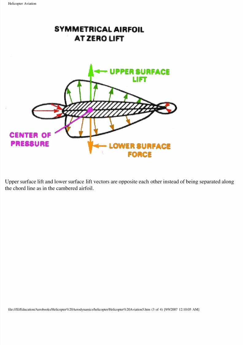
essure patterns for symmetrical airfoils are distributed differently than for nonsymmetrical airfoils
le:///E|/Education/Aerobooks/Helicopter%20Aerodynamics/helicopter/Helicopter%20Aviation5.htm (2 of 4) [9/9/2007 12:10:05 AM]
8/8/2019 Helicopter Fundamentals
http://slidepdf.com/reader/full/helicopter-fundamentals 14/66
Helicopter Aviation
pper surface lift and lower surface lift vectors are opposite each other instead of being separated aloe chord line as in the cambered airfoil.
le:///E|/Education/Aerobooks/Helicopter%20Aerodynamics/helicopter/Helicopter%20Aviation5.htm (3 of 4) [9/9/2007 12:10:05 AM]
8/8/2019 Helicopter Fundamentals
http://slidepdf.com/reader/full/helicopter-fundamentals 15/66
Helicopter Aviation
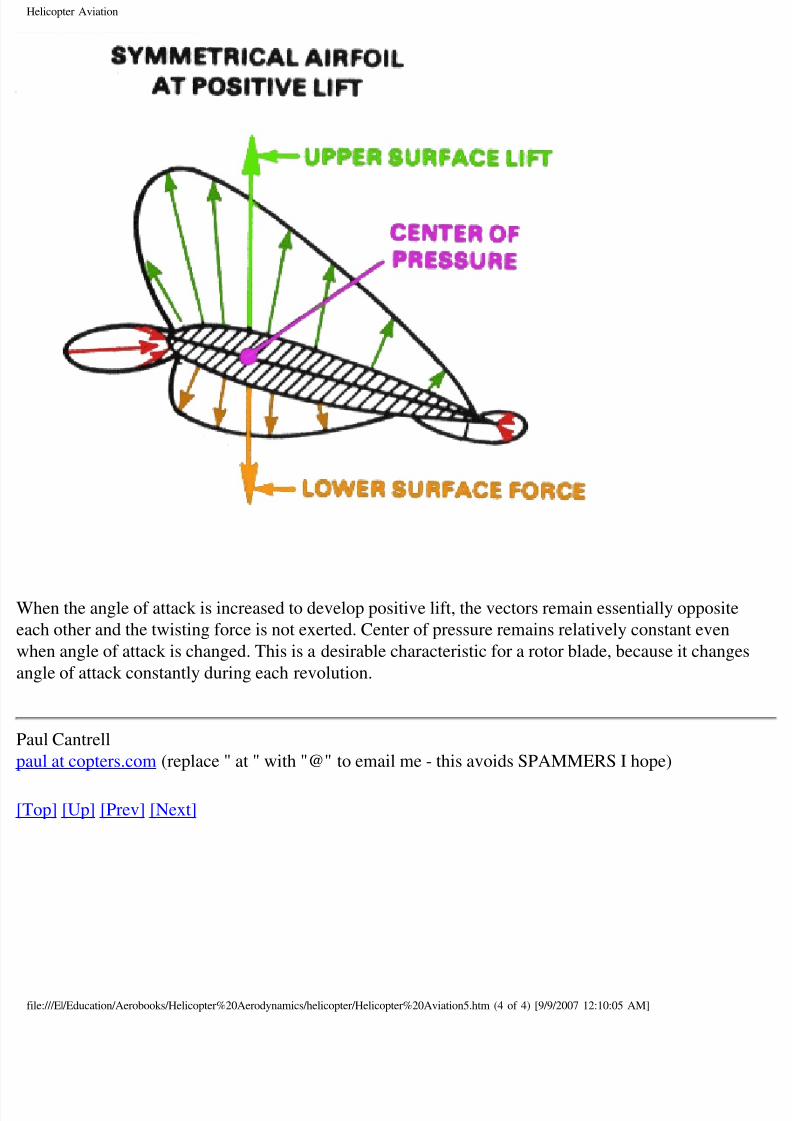
hen the angle of attack is increased to develop positive lift, the vectors remain essentially opposite
ch other and the twisting force is not exerted. Center of pressure remains relatively constant even
hen angle of attack is changed. This is a desirable characteristic for a rotor blade, because it change
gle of attack constantly during each revolution.
aul Cantrell
ul at copters.com (replace " at " with "@" to email me - this avoids SPAMMERS I hope)
op] [Up] [Prev] [Next]
le:///E|/Education/Aerobooks/Helicopter%20Aerodynamics/helicopter/Helicopter%20Aviation5.htm (4 of 4) [9/9/2007 12:10:05 AM]
8/8/2019 Helicopter Fundamentals
http://slidepdf.com/reader/full/helicopter-fundamentals 16/66
Helicopter Aviation
op] [Up] [Prev] [Next]
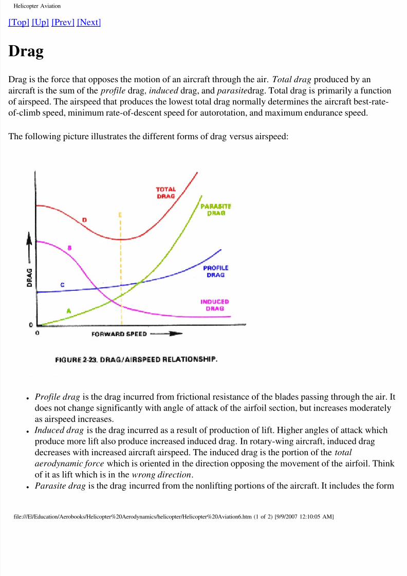
Drag
rag is the force that opposes the motion of an aircraft through the air. Total drag produced by an
rcraft is the sum of the profile drag, induced drag, and parasitedrag. Total drag is primarily a functi
airspeed. The airspeed that produces the lowest total drag normally determines the aircraft best-rat-climb speed, minimum rate-of-descent speed for autorotation, and maximum endurance speed.
he following picture illustrates the different forms of drag versus airspeed:
● Profile drag is the drag incurred from frictional resistance of the blades passing through the a
does not change significantly with angle of attack of the airfoil section, but increases moderat
as airspeed increases.
● Induced drag is the drag incurred as a result of production of lift. Higher angles of attack whic
produce more lift also produce increased induced drag. In rotary-wing aircraft, induced drag
decreases with increased aircraft airspeed. The induced drag is the portion of the total
aerodynamic force which is oriented in the direction opposing the movement of the airfoil. Th
of it as lift which is in the wrong direction.
● Parasite drag is the drag incurred from the nonlifting portions of the aircraft. It includes the f
le:///E|/Education/Aerobooks/Helicopter%20Aerodynamics/helicopter/Helicopter%20Aviation6.htm (1 of 2) [9/9/2007 12:10:05 AM]
8/8/2019 Helicopter Fundamentals
http://slidepdf.com/reader/full/helicopter-fundamentals 17/66
Helicopter Aviation
drag and skin friction associated with the fuselage, cockpit, engine cowlings, rotor hub, landin
gear, and tail boom to mention a few. Parasite drag increases with airspeed.
urve "A" shows that parasite drag is very low at slow airspeeds and increases with higher airspeeds
arasite drag goes up at an increasing rate at airspeeds above the midrange.
urve "B" shows how induced drag decreases as aircraft airspeed increases. At a hover, or at lower
rspeeds, induced drag is highest. It decreases as airspeed increases and the helicopter moves intondisturbed air.
urve "C" shows the profile drag curve. Profile drag remains relatively constant throughout the spee
nge with some increase at the higher airspeeds.
urve "D" shows total drag and represents the sum of the other three curves. It identifies the airspeed
nge, line "E", at which total drag is lowest. That airspeed is the best airspeed for maximum enduran
st rate of climb, and minimum rate of descent in autorotation.
aul Cantrell
ul at copters.com (replace " at " with "@" to email me - this avoids SPAMMERS I hope)
op] [Up] [Prev] [Next]
le:///E|/Education/Aerobooks/Helicopter%20Aerodynamics/helicopter/Helicopter%20Aviation6.htm (2 of 2) [9/9/2007 12:10:05 AM]
8/8/2019 Helicopter Fundamentals
http://slidepdf.com/reader/full/helicopter-fundamentals 18/66
Helicopter Aviation
op] [Up] [Prev] [Next]
Centrifugal Force
elicopter rotor systems depend primarily on rotation to produce relative wind which develops the
rodynamic force required for flight. Because of its rotation and weight, the rotor system is subject
rces and moments peculiar to all rotating masses. One of the forces produced is centrifugal force. Ifined as the force that tends to make rotating bodies move away from the center of rotation. Anoth
rce produced in the rotor system is centripetal force. It is the force that counteracts centrifugal forc
y keeping an object a certain radius from the axis of rotation.
he rotating blades of a helicopter produce very high centrifugal loads on the rotor head and blade
tachement assemblies. As a matter of interest, centrifugal loads may be from 6 to 12 tons at the bla
ot of two to four passenger helicopters. Larger helicopters may develop up to 40 tons of centrifuga
ad on each blade root. In rotary-wing aircraft, centrifugal force is the dominant force affecting the
tor system. All other forces act to modify this force.
hen the rotor blades are at rest, they droop due to their weight and span. In fully articulated system
ey rest against a static or droop stop which prevents the blade from descending so low it will strike
rcraft (or ground!). When the rotor system begins to turn, the blade starts to rise from the static
osition because of the centrifugal force. At operating speed, the blades extend straight out even thou
ey are at flat pitch and are not producing lift.
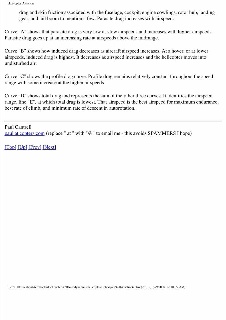
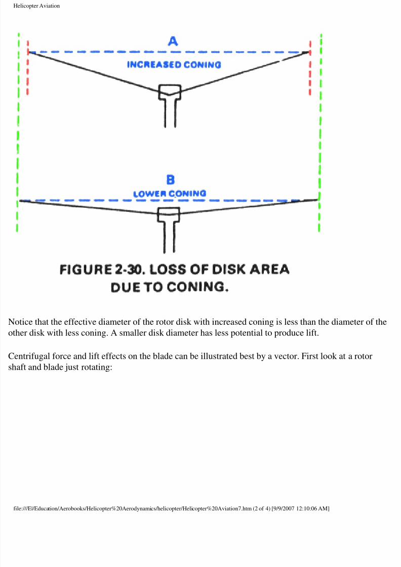
s the helicopter develops lift during takeoff and flight, the blades rise above the "straight out" posit
d assume a coned position. Amount of coning depends on RPM, gross weight, and G-Forces
perienced during flight. If RPM is held constant, coning increases as gross weight and G-force
crease. If gross weight and G-forces are constant, decreasing RPM will cause increased coning.
xcessive coning can occur if RPM gets too low, gross weight is too high, or if excessive G-forces a
perienced. Excessive coning can cause undesirable stresses on the blade and a decrease of total lift
cause of a decrease in effective disk area:
le:///E|/Education/Aerobooks/Helicopter%20Aerodynamics/helicopter/Helicopter%20Aviation7.htm (1 of 4) [9/9/2007 12:10:06 AM]
8/8/2019 Helicopter Fundamentals
http://slidepdf.com/reader/full/helicopter-fundamentals 19/66
Helicopter Aviation
otice that the effective diameter of the rotor disk with increased coning is less than the diameter of
her disk with less coning. A smaller disk diameter has less potential to produce lift.
entrifugal force and lift effects on the blade can be illustrated best by a vector. First look at a rotor
aft and blade just rotating:
le:///E|/Education/Aerobooks/Helicopter%20Aerodynamics/helicopter/Helicopter%20Aviation7.htm (2 of 4) [9/9/2007 12:10:06 AM]
8/8/2019 Helicopter Fundamentals
http://slidepdf.com/reader/full/helicopter-fundamentals 20/66
Helicopter Aviation
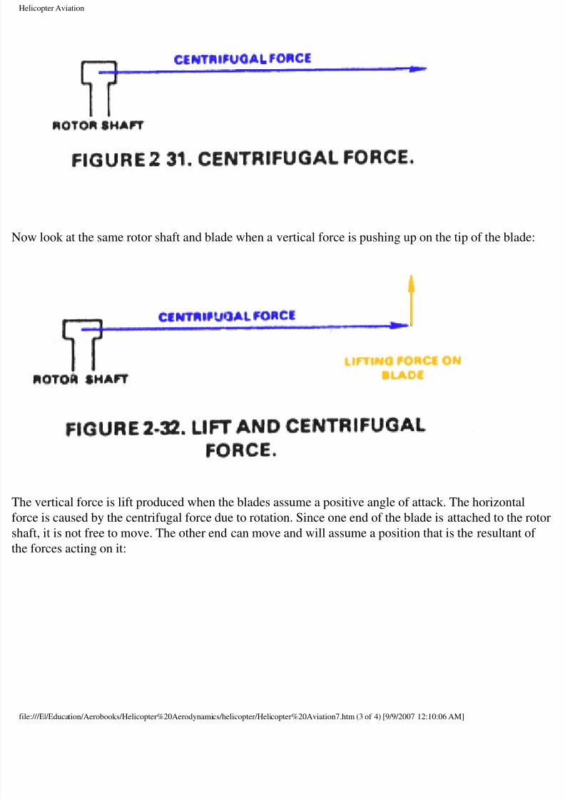
ow look at the same rotor shaft and blade when a vertical force is pushing up on the tip of the blade
he vertical force is lift produced when the blades assume a positive angle of attack. The horizontal
rce is caused by the centrifugal force due to rotation. Since one end of the blade is attached to the r
aft, it is not free to move. The other end can move and will assume a position that is the resultant o
e forces acting on it:
le:///E|/Education/Aerobooks/Helicopter%20Aerodynamics/helicopter/Helicopter%20Aviation7.htm (3 of 4) [9/9/2007 12:10:06 AM]
8/8/2019 Helicopter Fundamentals
http://slidepdf.com/reader/full/helicopter-fundamentals 21/66
Helicopter Aviation
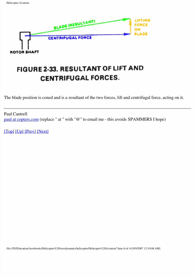
he blade position is coned and is a resultant of the two forces, lift and centrifugal force, acting on it
aul Cantrell
ul at copters.com (replace " at " with "@" to email me - this avoids SPAMMERS I hope)
op] [Up] [Prev] [Next]
le:///E|/Education/Aerobooks/Helicopter%20Aerodynamics/helicopter/Helicopter%20Aviation7.htm (4 of 4) [9/9/2007 12:10:06 AM]
8/8/2019 Helicopter Fundamentals
http://slidepdf.com/reader/full/helicopter-fundamentals 22/66
Helicopter Aviation
op] [Up] [Prev] [Next]
Rotational Velocities
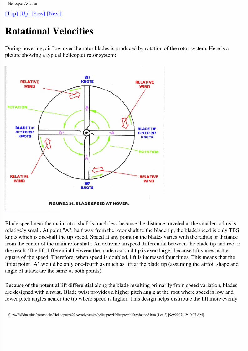
uring hovering, airflow over the rotor blades is produced by rotation of the rotor system. Here is a
cture showing a typical helicopter rotor system:
ade speed near the main rotor shaft is much less because the distance traveled at the smaller radius
latively small. At point "A", half way from the rotor shaft to the blade tip, the blade speed is only T
nots which is one-half the tip speed. Speed at any point on the blades varies with the radius or distan
om the center of the main rotor shaft. An extreme airspeed differential between the blade tip and roe result. The lift differential between the blade root and tip is even larger because lift varies as the
uare of the speed. Therefore, when speed is doubled, lift is increased four times. This means that th
t at point "A" would be only one-fourth as much as lift at the blade tip (assuming the airfoil shape
gle of attack are the same at both points).
ecause of the potential lift differential along the blade resulting primarily from speed variation, blad
e designed with a twist. Blade twist provides a higher pitch angle at the root where speed is low an
wer pitch angles nearer the tip where speed is higher. This design helps distribute the lift more even
le:///E|/Education/Aerobooks/Helicopter%20Aerodynamics/helicopter/Helicopter%20Aviation8.htm (1 of 2) [9/9/2007 12:10:07 AM]
8/8/2019 Helicopter Fundamentals
http://slidepdf.com/reader/full/helicopter-fundamentals 23/66
Helicopter Aviation
ong the blade. It increases both the induced air velocity and the blade loading near the inboard sect
the blade.
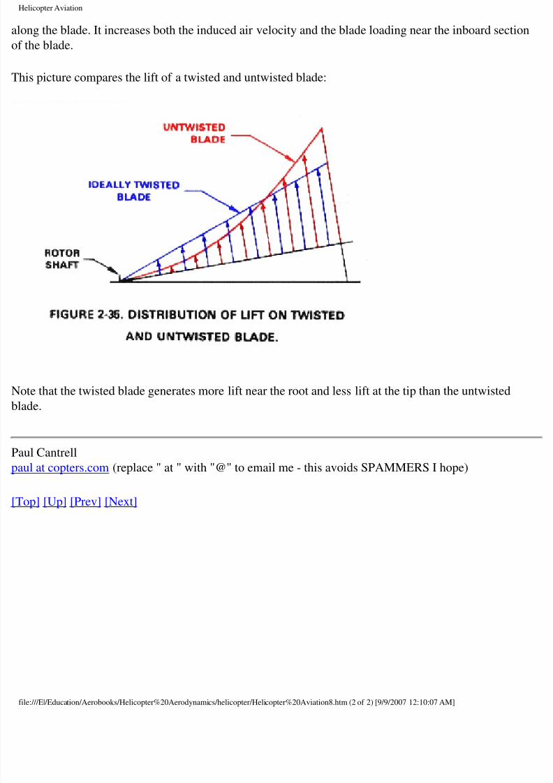
his picture compares the lift of a twisted and untwisted blade:
ote that the twisted blade generates more lift near the root and less lift at the tip than the untwisted
ade.
aul Cantrell
ul at copters.com (replace " at " with "@" to email me - this avoids SPAMMERS I hope)
op] [Up] [Prev] [Next]
le:///E|/Education/Aerobooks/Helicopter%20Aerodynamics/helicopter/Helicopter%20Aviation8.htm (2 of 2) [9/9/2007 12:10:07 AM]
8/8/2019 Helicopter Fundamentals
http://slidepdf.com/reader/full/helicopter-fundamentals 24/66
Helicopter Aviation
op] [Up] [Prev] [Next]
Hovering
overing is the term applied when a helicopter maintains a constant position at a selected point, usua
few feet above the ground (but not always, helicopters can hover high in the air, given sufficient
ower). For a helicopter to hover, the main rotor must supply lift equal to the total weight of thelicopter. With the blades rotating at high velocity, an increase of blade pitch (angle of attack) woul
duce the necessary lift for a hover. The forces of lift and weight reach a state of balance during a
ationary hover.
overing is actually an element of vertical flight. Assuming a no-wind condition, the tip-path plane o
e blades will remain horizontal. If the angle of attack of the blades is increased while their velocity
mains constant, additional vertical thrust is obtained. Thus, by upsetting the vertical balance of forc
licopters can climb or descend vertically.
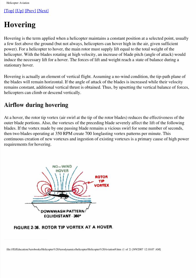
irflow during hovering
t a hover, the rotor tip vortex (air swirl at the tip of the rotor blades) reduces the effectiveness of the
uter blade portions. Also, the vortexes of the preceding blade severely affect the lift of the following
ades. If the vortex made by one passing blade remains a vicious swirl for some number of seconds,
en two blades operating at 350 RPM create 700 longlasting vortex patterns per minute. This
ntinuous creation of new vortexes and ingestion of existing vortexes is a primary cause of high pow
quirements for hovering.
le:///E|/Education/Aerobooks/Helicopter%20Aerodynamics/helicopter/Helicopter%20Aviation9.htm (1 of 2) [9/9/2007 12:10:07 AM]
8/8/2019 Helicopter Fundamentals
http://slidepdf.com/reader/full/helicopter-fundamentals 25/66
Helicopter Aviation
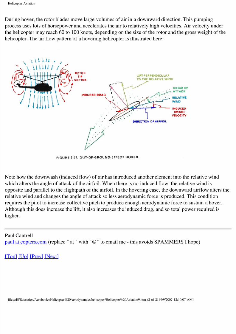
uring hover, the rotor blades move large volumes of air in a downward direction. This pumping
ocess uses lots of horsepower and accelerates the air to relatively high velocities. Air velocity unde
e helicopter may reach 60 to 100 knots, depending on the size of the rotor and the gross weight of t
licopter. The air flow pattern of a hovering helicopter is illustrated here:
ote how the downwash (induced flow) of air has introduced another element into the relative windhich alters the angle of attack of the airfoil. When there is no induced flow, the relative wind is
pposite and parallel to the flightpath of the airfoil. In the hovering case, the downward airflow alter
lative wind and changes the angle of attack so less aerodynamic force is produced. This condition
quires the pilot to increase collective pitch to produce enough aerodynamic force to sustain a hover
lthough this does increase the lift, it also increases the induced drag, and so total power required is
gher.
aul Cantrellul at copters.com (replace " at " with "@" to email me - this avoids SPAMMERS I hope)
op] [Up] [Prev] [Next]
le:///E|/Education/Aerobooks/Helicopter%20Aerodynamics/helicopter/Helicopter%20Aviation9.htm (2 of 2) [9/9/2007 12:10:07 AM]
8/8/2019 Helicopter Fundamentals
http://slidepdf.com/reader/full/helicopter-fundamentals 26/66
Helicopter Aviation
op] [Up] [Prev] [Next]
Ground effect
he high power requirement needed to hover out of ground effect is reduced when operating in groun
fect. Ground effect is a condition of improved performance encountered when operating near (with
2 rotor diameter) of the ground. It is due to the interference of the surface with the airflow pattern oe rotor system, and it is more pronounced the nearer the ground is approached. Increased blade
ficiency while operating in ground effect is due to two separate and distinct phenomena.
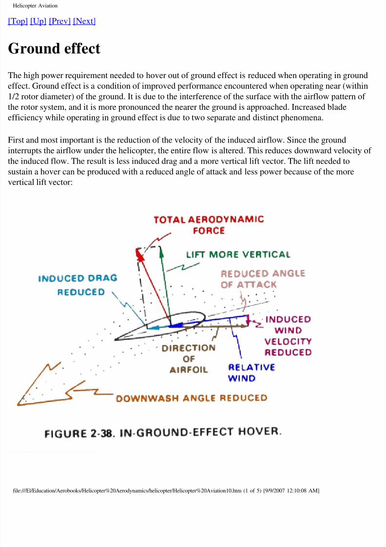
rst and most important is the reduction of the velocity of the induced airflow. Since the ground
terrupts the airflow under the helicopter, the entire flow is altered. This reduces downward velocity
e induced flow. The result is less induced drag and a more vertical lift vector. The lift needed to
stain a hover can be produced with a reduced angle of attack and less power because of the more
rtical lift vector:
le:///E|/Education/Aerobooks/Helicopter%20Aerodynamics/helicopter/Helicopter%20Aviation10.htm (1 of 5) [9/9/2007 12:10:08 AM]
8/8/2019 Helicopter Fundamentals
http://slidepdf.com/reader/full/helicopter-fundamentals 27/66
Helicopter Aviation
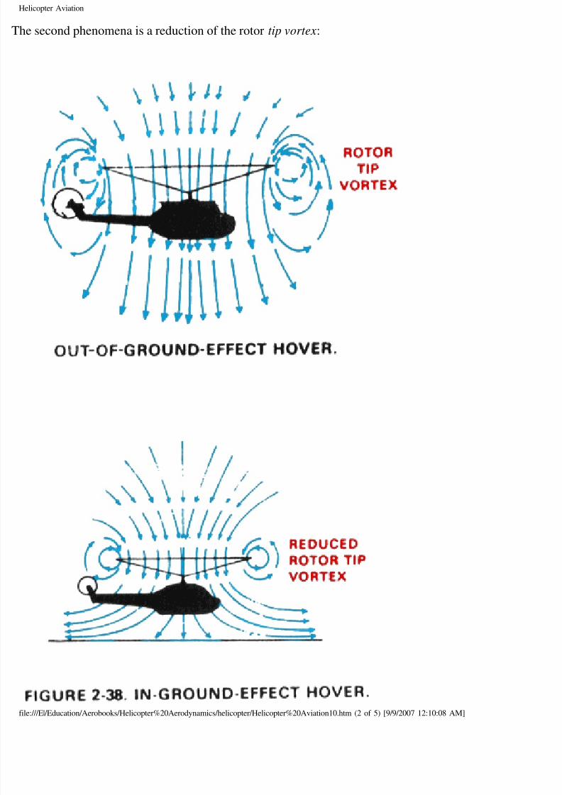
he second phenomena is a reduction of the rotor tip vortex:
le:///E|/Education/Aerobooks/Helicopter%20Aerodynamics/helicopter/Helicopter%20Aviation10.htm (2 of 5) [9/9/2007 12:10:08 AM]
8/8/2019 Helicopter Fundamentals
http://slidepdf.com/reader/full/helicopter-fundamentals 28/66
Helicopter Aviation
hen operating in ground effect, the downward and outward airflow pattern tends to restrict vortex
neration. This makes the outboard portion of the rotor blade more efficient and reduces overall sys
rbulence caused by ingestion and recirculation of the vortex swirls.
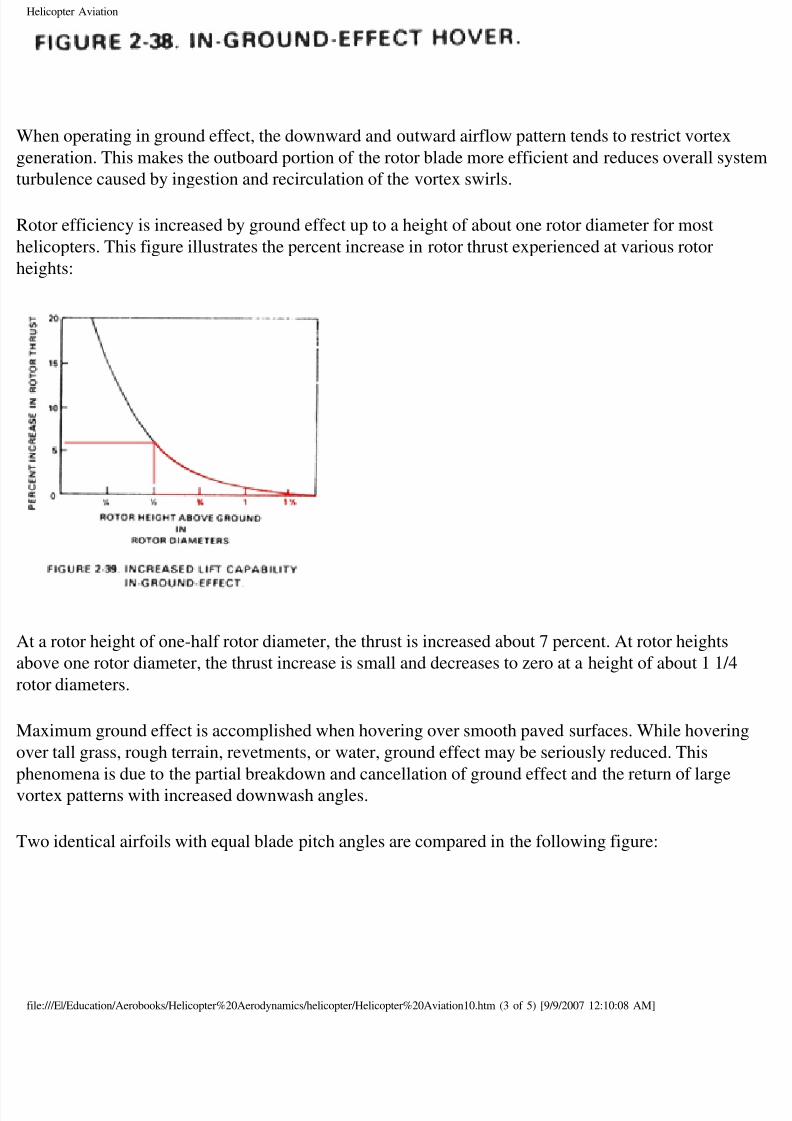
otor efficiency is increased by ground effect up to a height of about one rotor diameter for most
licopters. This figure illustrates the percent increase in rotor thrust experienced at various rotor
ights:
t a rotor height of one-half rotor diameter, the thrust is increased about 7 percent. At rotor heights
ove one rotor diameter, the thrust increase is small and decreases to zero at a height of about 1 1/4
tor diameters.
aximum ground effect is accomplished when hovering over smooth paved surfaces. While hoverin
ver tall grass, rough terrain, revetments, or water, ground effect may be seriously reduced. This
henomena is due to the partial breakdown and cancellation of ground effect and the return of large
ortex patterns with increased downwash angles.
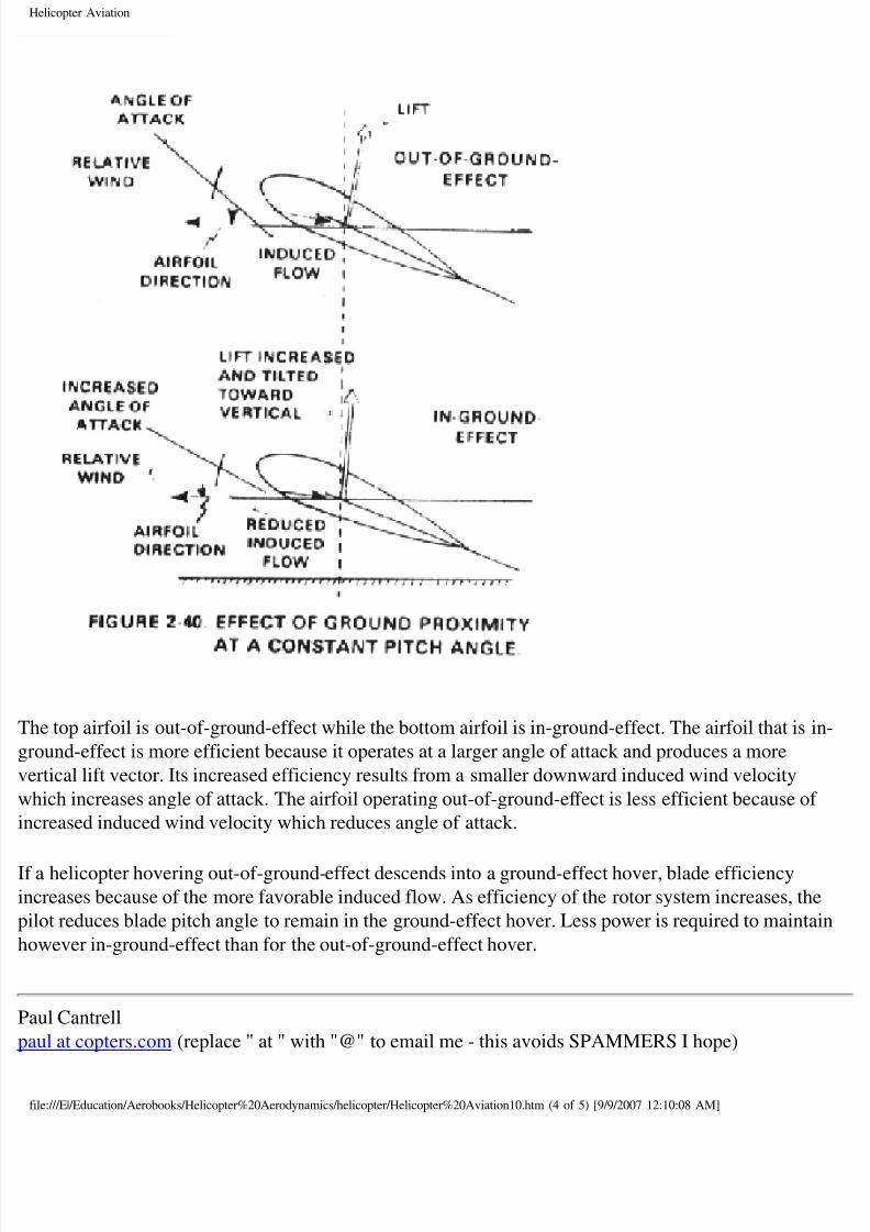
wo identical airfoils with equal blade pitch angles are compared in the following figure:
le:///E|/Education/Aerobooks/Helicopter%20Aerodynamics/helicopter/Helicopter%20Aviation10.htm (3 of 5) [9/9/2007 12:10:08 AM]
8/8/2019 Helicopter Fundamentals
http://slidepdf.com/reader/full/helicopter-fundamentals 29/66
Helicopter Aviation
he top airfoil is out-of-ground-effect while the bottom airfoil is in-ground-effect. The airfoil that is
ound-effect is more efficient because it operates at a larger angle of attack and produces a more
rtical lift vector. Its increased efficiency results from a smaller downward induced wind velocity
hich increases angle of attack. The airfoil operating out-of-ground-effect is less efficient because of
creased induced wind velocity which reduces angle of attack.
a helicopter hovering out-of-ground-effect descends into a ground-effect hover, blade efficiency
creases because of the more favorable induced flow. As efficiency of the rotor system increases, th
lot reduces blade pitch angle to remain in the ground-effect hover. Less power is required to mainta
owever in-ground-effect than for the out-of-ground-effect hover.
aul Cantrell
ul at copters.com (replace " at " with "@" to email me - this avoids SPAMMERS I hope)
le:///E|/Education/Aerobooks/Helicopter%20Aerodynamics/helicopter/Helicopter%20Aviation10.htm (4 of 5) [9/9/2007 12:10:08 AM]

8/8/2019 Helicopter Fundamentals
http://slidepdf.com/reader/full/helicopter-fundamentals 30/66
Helicopter Aviation
op] [Up] [Prev] [Next]
le:///E|/Education/Aerobooks/Helicopter%20Aerodynamics/helicopter/Helicopter%20Aviation10.htm (5 of 5) [9/9/2007 12:10:08 AM]
8/8/2019 Helicopter Fundamentals
http://slidepdf.com/reader/full/helicopter-fundamentals 31/66
Helicopter Aviation
op] [Up] [Prev] [Next]
Torque
accordance with Newton's law of action and reaction, the helicopter fuselage tends to rotate in the
rection opposite to the rotor blades. This effect is called torque. Torque must be counteracted and o
ntrolled before flight is possible. In tandem rotor and coaxial helicopter designs, the rotors turn inpposite directions to neutralize or eliminate torque effects. In tip-jet helicopters, power originates at
ade tip and equal and opposite reaction is against the air; there is no torque between the rotor and th
selage. However, the torque problem is especially important in single main rotor helicopters with a
selage mounted power source. The torque effect on the fuselage is a direct result of the work/
sistance of the main rotor. Therefore torque is at the geometric center of the main rotor. Torque res
om the rotor being driven by the engine power output. Any change in engine power output brings
out a corresponding change in torque effect. Furthermore, power varies with the flight maneuver a
sults in a variable torque effect that must be continually corrected.
ntitorque Rotor
ompensation for torque in the single main rotor helicopter is accomplished by means of a variable
tch antitorque rotor (tail rotor) located on the end of a tail boom extension at the rear of the fuselag
riven by the main rotor at a constant ratio, the tail rotor produces thrust in a horizontal plane oppos
torque reaction developed by the main rotor. Since torque effect varies during flight when power
anges are made, it is necessary to vary the thrust of the tail rotor. Antitorque pedals enable the pilo
mpensate for torque variance. A significant part of the engine power is required to drive the tail ro
pecially during operations when maximum power is used. From 5 to 30 percent of the available en
ower may be needed to drive the tail rotor depending on helicopter size and design. Normally, large
licopters use a higher percent of engine power to counteract torque than do smaller aircraft. A
licopter with 9,500 horsepower might require 1,200 horsepower to drive the tail rotor, while a 200
orsepower aircraft might require only 10 horsepower for torque correction.
Heading Control
addition to counteracting torque, the tail rotor and its control linkage also permit control of thelicopter heading during flight. Application of more control than is necessary to counteract torque w
use the nose of the helicopter to swing in the direction of pedal movement. To maintain a constant
ading at a hover or during takeoff or approach, the pilot must use antitorque pedals to apply just
ough pitch on the tail rotor to neutralize torque and hold a slip if necessary. Heading control in
rward trimmed flight is normally accomplished with cyclic control, using a coordinated bank and t
the desired heading. Application of antitorque pedals will be required when power changes are ma
an autorotation, some degree of right pedal is required to maintain correct trim. When torque is no
le:///E|/Education/Aerobooks/Helicopter%20Aerodynamics/helicopter/Helicopter%20Aviation11.htm (1 of 2) [9/9/2007 12:10:09 AM]
8/8/2019 Helicopter Fundamentals
http://slidepdf.com/reader/full/helicopter-fundamentals 32/66
Helicopter Aviation
esent, mast thrust bearing friction tends to turn the fuselage in the same direction as main rotor
tation. To counteract this friction, the tail rotor thrust is applied in an opposite direction to counter
ctional forces.
ranslating tendency
uring hovering flight, the single rotor helicopter has a tendency to drift laterally to the right due to tteral thrust being supplied by the tail rotor. The pilot may prevent right lateral drift of the helicopte
ting the main rotor disk to the left. This lateral tilt results in a main rotor force to the left that
mpensates for the tail rotor thrust to the right.
elicopter design usually includes one or more features which help the pilot compensate for translati
ndency.
● Flight control rigging may be designed so the rotor disk is tilted slightly left when the cyclic
control is centered.● The collective pitch control system may be designed so that the rotor disk tilts slightly left as
collective pitch is increased to hover the aircraft.
● The main transmission may be mounted so that the mast is tilted slightly to the left when the
helicopter fuselage is laterally level.
aul Cantrell
ul at copters.com (replace " at " with "@" to email me - this avoids SPAMMERS I hope)
op] [Up] [Prev] [Next]
le:///E|/Education/Aerobooks/Helicopter%20Aerodynamics/helicopter/Helicopter%20Aviation11.htm (2 of 2) [9/9/2007 12:10:09 AM]
8/8/2019 Helicopter Fundamentals
http://slidepdf.com/reader/full/helicopter-fundamentals 33/66
Helicopter Aviation
op] [Up] [Prev] [Next]
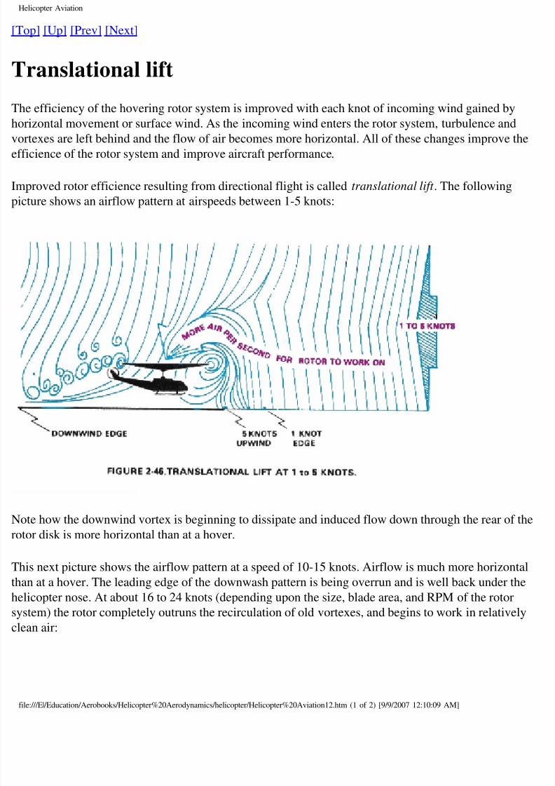
Translational lift
he efficiency of the hovering rotor system is improved with each knot of incoming wind gained by
orizontal movement or surface wind. As the incoming wind enters the rotor system, turbulence and
ortexes are left behind and the flow of air becomes more horizontal. All of these changes improve thficience of the rotor system and improve aircraft performance.
mproved rotor efficience resulting from directional flight is called translational lift . The following
cture shows an airflow pattern at airspeeds between 1-5 knots:
ote how the downwind vortex is beginning to dissipate and induced flow down through the rear of
tor disk is more horizontal than at a hover.
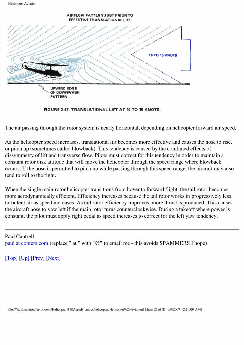
his next picture shows the airflow pattern at a speed of 10-15 knots. Airflow is much more horizont
an at a hover. The leading edge of the downwash pattern is being overrun and is well back under th
licopter nose. At about 16 to 24 knots (depending upon the size, blade area, and RPM of the rotor
stem) the rotor completely outruns the recirculation of old vortexes, and begins to work in relativel
ean air:
le:///E|/Education/Aerobooks/Helicopter%20Aerodynamics/helicopter/Helicopter%20Aviation12.htm (1 of 2) [9/9/2007 12:10:09 AM]
8/8/2019 Helicopter Fundamentals
http://slidepdf.com/reader/full/helicopter-fundamentals 34/66
Helicopter Aviation
he air passing through the rotor system is nearly horizontal, depending on helicopter forward air spe
s the helicopter speed increases, translational lift becomes more effective and causes the nose to ris
pitch up (sometimes called blowback). This tendency is caused by the combined effects of
ssymmetry of lift and transverse flow. Pilots must correct for this tendency in order to maintain a
nstant rotor disk attitude that will move the helicopter through the speed range where blowback
curs. If the nose is permitted to pitch up while passing through this speed range, the aircraft may al
nd to roll to the right.
hen the single main rotor helicopter transitions from hover to forward flight, the tail rotor becomes
ore aerodynamically efficient. Efficiency increases because the tail rotor works in progressively les
rbulent air as speed increases. As tail rotor efficiency improves, more thrust is produced. This caus
e aircraft nose to yaw left if the main rotor turns counterclockwise. During a takeoff where power i
nstant, the pilot must apply right pedal as speed increases to correct for the left yaw tendency.
aul Cantrell
ul at copters.com (replace " at " with "@" to email me - this avoids SPAMMERS I hope)
op] [Up] [Prev] [Next]
le:///E|/Education/Aerobooks/Helicopter%20Aerodynamics/helicopter/Helicopter%20Aviation12.htm (2 of 2) [9/9/2007 12:10:09 AM]
8/8/2019 Helicopter Fundamentals
http://slidepdf.com/reader/full/helicopter-fundamentals 35/66
Helicopter Aviation
op] [Up] [Prev] [Next]
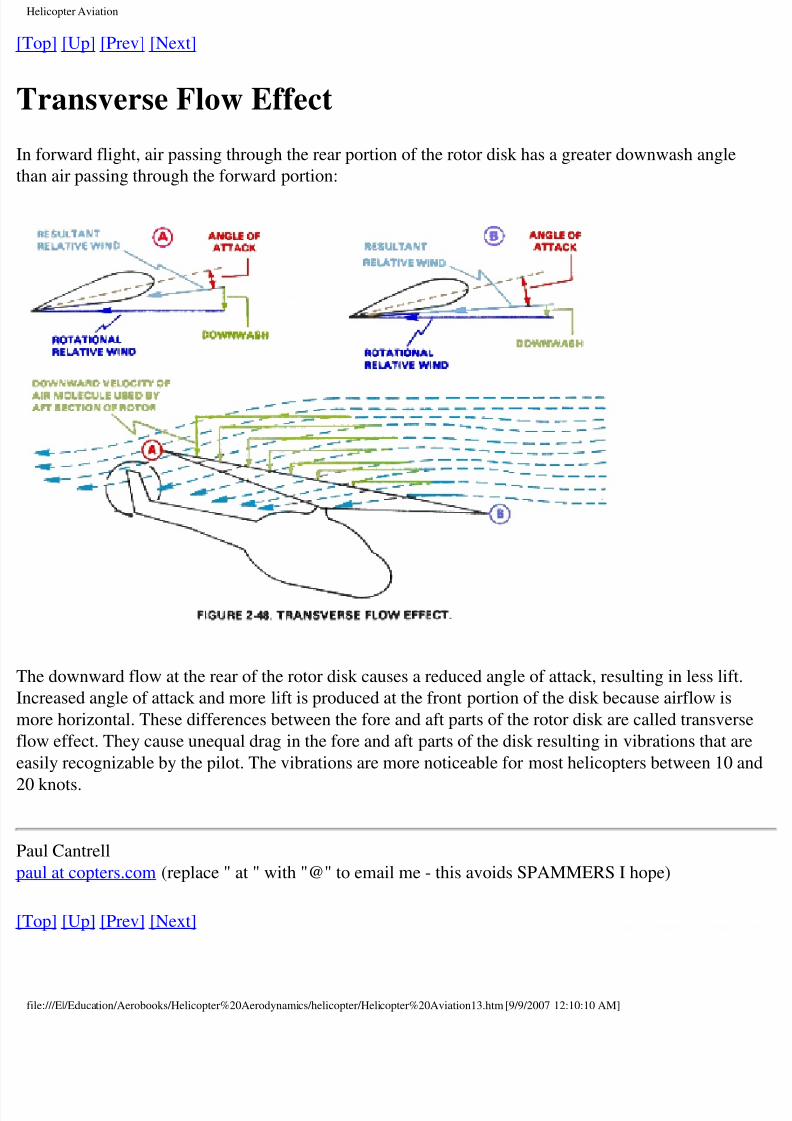
Transverse Flow Effect
forward flight, air passing through the rear portion of the rotor disk has a greater downwash angle
an air passing through the forward portion:
he downward flow at the rear of the rotor disk causes a reduced angle of attack, resulting in less lift
creased angle of attack and more lift is produced at the front portion of the disk because airflow is
ore horizontal. These differences between the fore and aft parts of the rotor disk are called transver
ow effect. They cause unequal drag in the fore and aft parts of the disk resulting in vibrations that a
sily recognizable by the pilot. The vibrations are more noticeable for most helicopters between 10
0 knots.
aul Cantrell
ul at copters.com (replace " at " with "@" to email me - this avoids SPAMMERS I hope)
op] [Up] [Prev] [Next]
le:///E|/Education/Aerobooks/Helicopter%20Aerodynamics/helicopter/Helicopter%20Aviation13.htm [9/9/2007 12:10:10 AM]
8/8/2019 Helicopter Fundamentals
http://slidepdf.com/reader/full/helicopter-fundamentals 36/66
Helicopter Aviation
op] [Up] [Prev] [Next]
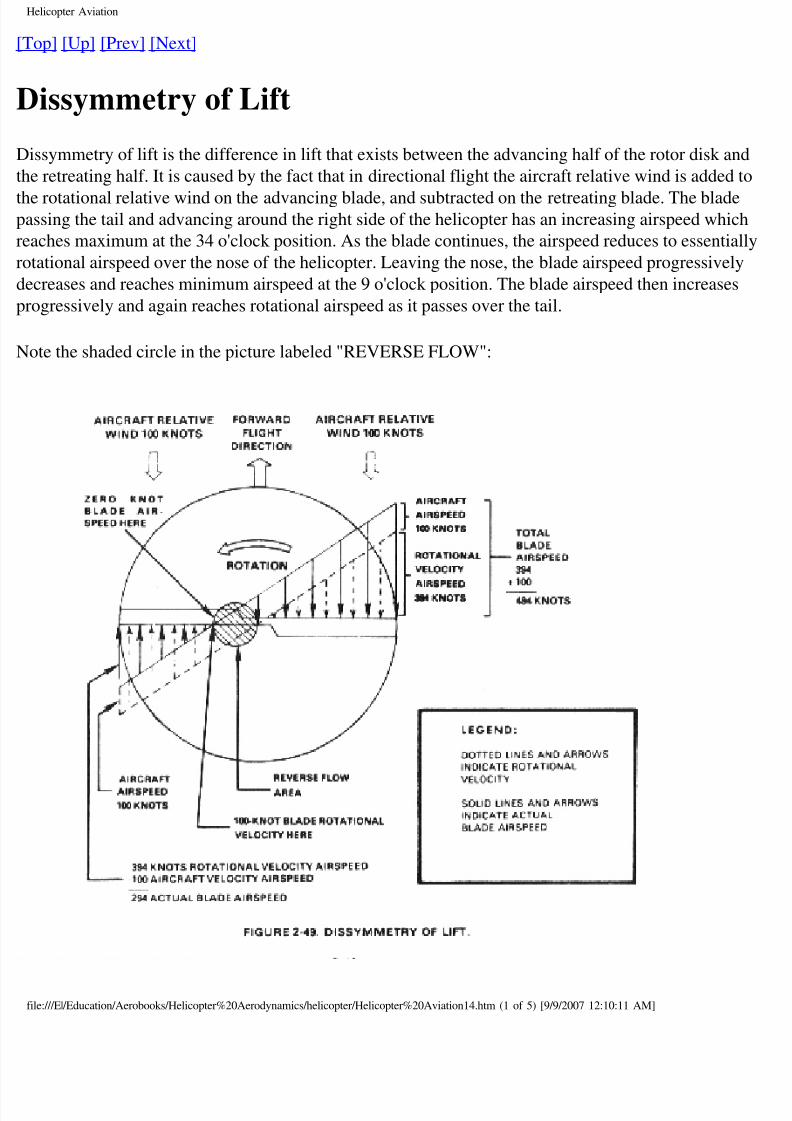
Dissymmetry of Lift
issymmetry of lift is the difference in lift that exists between the advancing half of the rotor disk an
e retreating half. It is caused by the fact that in directional flight the aircraft relative wind is added
e rotational relative wind on the advancing blade, and subtracted on the retreating blade. The bladessing the tail and advancing around the right side of the helicopter has an increasing airspeed whic
aches maximum at the 34 o'clock position. As the blade continues, the airspeed reduces to essential
tational airspeed over the nose of the helicopter. Leaving the nose, the blade airspeed progressively
creases and reaches minimum airspeed at the 9 o'clock position. The blade airspeed then increases
ogressively and again reaches rotational airspeed as it passes over the tail.
ote the shaded circle in the picture labeled "REVERSE FLOW":
le:///E|/Education/Aerobooks/Helicopter%20Aerodynamics/helicopter/Helicopter%20Aviation14.htm (1 of 5) [9/9/2007 12:10:11 AM]
8/8/2019 Helicopter Fundamentals
http://slidepdf.com/reader/full/helicopter-fundamentals 37/66
Helicopter Aviation
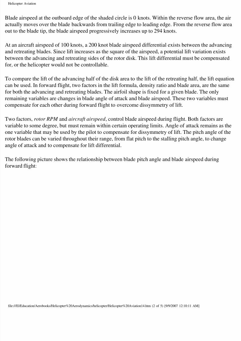
ade airspeed at the outboard edge of the shaded circle is 0 knots. Within the reverse flow area, the
tually moves over the blade backwards from trailing edge to leading edge. From the reverse flow a
ut to the blade tip, the blade airspeed progressively increases up to 294 knots.
t an aircraft airspeed of 100 knots, a 200 knot blade airspeed differential exists between the advanc
d retreating blades. Since lift increases as the square of the airspeed, a potential lift variation exists
tween the advancing and retreating sides of the rotor disk. This lift differential must be compensater, or the helicopter would not be controllable.
o compare the lift of the advancing half of the disk area to the lift of the retreating half, the lift equa
n be used. In forward flight, two factors in the lift formula, density ratio and blade area, are the sam
r both the advancing and retreating blades. The airfoil shape is fixed for a given blade. The only
maining variables are changes in blade angle of attack and blade airspeed. These two variables mus
mpensate for each other during forward flight to overcome dissymmetry of lift.
wo factors, rotor RPM and aircraft airspeed , control blade airspeed during flight. Both factors areriable to some degree, but must remain within certain operating limits. Angle of attack remains as
ne variable that may be used by the pilot to compensate for dissymmetry of lift. The pitch angle of t
tor blades can be varied throughout their range, from flat pitch to the stalling pitch angle, to change
gle of attack and to compensate for lift differential.
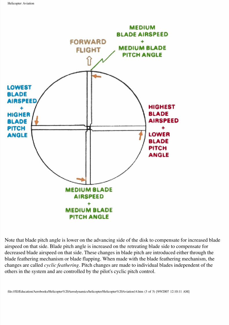
he following picture shows the relationship between blade pitch angle and blade airspeed during
rward flight:
le:///E|/Education/Aerobooks/Helicopter%20Aerodynamics/helicopter/Helicopter%20Aviation14.htm (2 of 5) [9/9/2007 12:10:11 AM]
8/8/2019 Helicopter Fundamentals
http://slidepdf.com/reader/full/helicopter-fundamentals 38/66
Helicopter Aviation
ote that blade pitch angle is lower on the advancing side of the disk to compensate for increased bla
rspeed on that side. Blade pitch angle is increased on the retreating blade side to compensate for
creased blade airspeed on that side. These changes in blade pitch are introduced either through the
ade feathering mechanism or blade flapping. When made with the blade feathering mechanism, the
anges are called cyclic feathering. Pitch changes are made to individual blades independent of the
hers in the system and are controlled by the pilot's cyclic pitch control.
le:///E|/Education/Aerobooks/Helicopter%20Aerodynamics/helicopter/Helicopter%20Aviation14.htm (3 of 5) [9/9/2007 12:10:11 AM]
8/8/2019 Helicopter Fundamentals
http://slidepdf.com/reader/full/helicopter-fundamentals 39/66
Helicopter Aviation
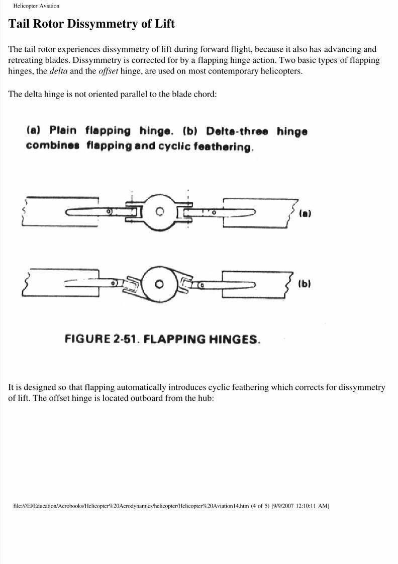
ail Rotor Dissymmetry of Lift
he tail rotor experiences dissymmetry of lift during forward flight, because it also has advancing an
treating blades. Dissymmetry is corrected for by a flapping hinge action. Two basic types of flappi
nges, the delta and the offset hinge, are used on most contemporary helicopters.
he delta hinge is not oriented parallel to the blade chord:
is designed so that flapping automatically introduces cyclic feathering which corrects for dissymm
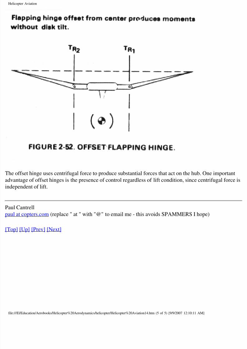
lift. The offset hinge is located outboard from the hub:
le:///E|/Education/Aerobooks/Helicopter%20Aerodynamics/helicopter/Helicopter%20Aviation14.htm (4 of 5) [9/9/2007 12:10:11 AM]
8/8/2019 Helicopter Fundamentals
http://slidepdf.com/reader/full/helicopter-fundamentals 40/66
Helicopter Aviation
he offset hinge uses centrifugal force to produce substantial forces that act on the hub. One importa
vantage of offset hinges is the presence of control regardless of lift condition, since centrifugal for
dependent of lift.
aul Cantrell
ul at copters.com (replace " at " with "@" to email me - this avoids SPAMMERS I hope)
op] [Up] [Prev] [Next]
le:///E|/Education/Aerobooks/Helicopter%20Aerodynamics/helicopter/Helicopter%20Aviation14.htm (5 of 5) [9/9/2007 12:10:11 AM]
8/8/2019 Helicopter Fundamentals
http://slidepdf.com/reader/full/helicopter-fundamentals 41/66
Helicopter Aviation
op] [Up] [Prev] [Next]
Flapping
apping can be pretty hard to understand at first, although it really is a fairly simple concept. A coup
ings you need to understand is the relationship between angle of attack and relative wind. Relative
ind is simply the direction the air seems to be coming at you because of your motion. When you stiour hand out of a moving car window, the wind hitting it seems to be coming from directly in front
ou. The wind will always seem to be moving in the opposite direction of your motion. For instance,
e car example, the car is moving forward, and the wind seems to be moving backward.
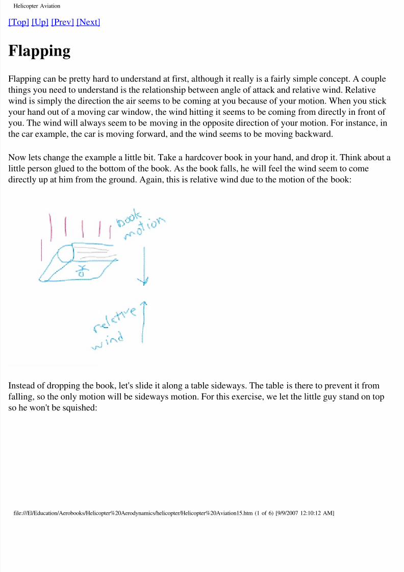
ow lets change the example a little bit. Take a hardcover book in your hand, and drop it. Think abo
tle person glued to the bottom of the book. As the book falls, he will feel the wind seem to come
rectly up at him from the ground. Again, this is relative wind due to the motion of the book:
stead of dropping the book, let's slide it along a table sideways. The table is there to prevent it from
lling, so the only motion will be sideways motion. For this exercise, we let the little guy stand on tohe won't be squished:
le:///E|/Education/Aerobooks/Helicopter%20Aerodynamics/helicopter/Helicopter%20Aviation15.htm (1 of 6) [9/9/2007 12:10:12 AM]
8/8/2019 Helicopter Fundamentals
http://slidepdf.com/reader/full/helicopter-fundamentals 42/66
Helicopter Aviation
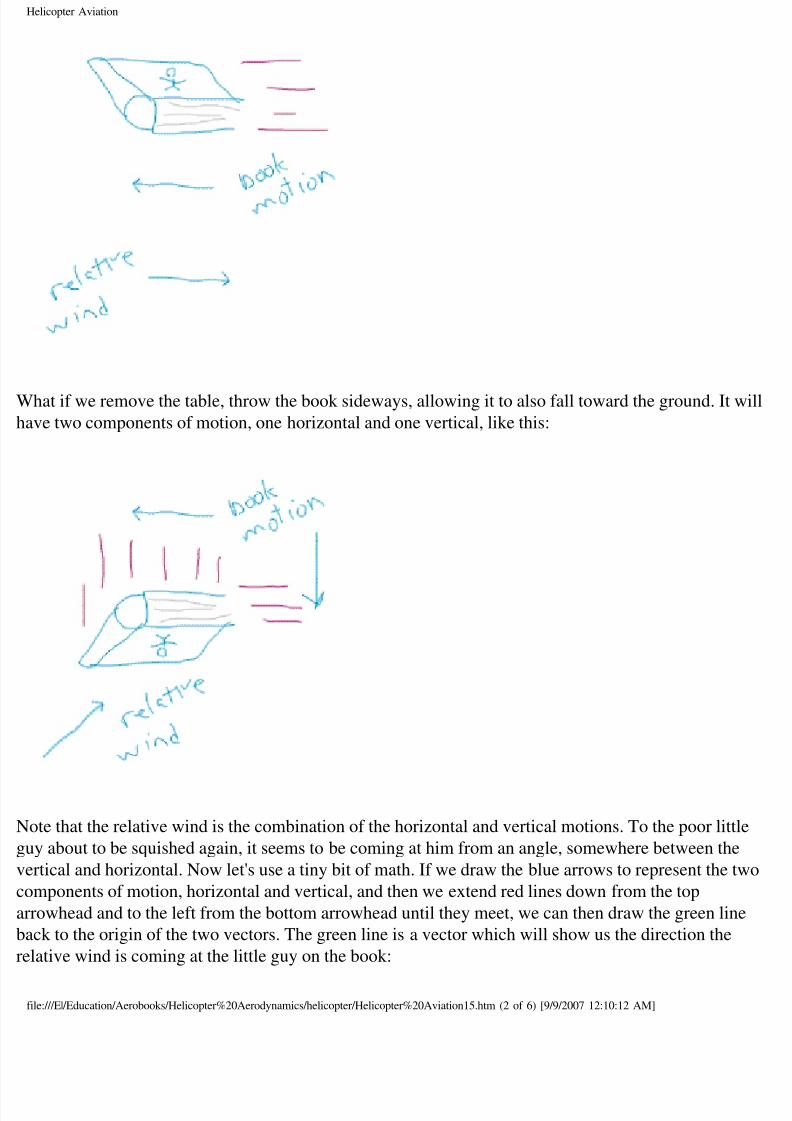
hat if we remove the table, throw the book sideways, allowing it to also fall toward the ground. It w
ve two components of motion, one horizontal and one vertical, like this:
ote that the relative wind is the combination of the horizontal and vertical motions. To the poor littl
uy about to be squished again, it seems to be coming at him from an angle, somewhere between the
rtical and horizontal. Now let's use a tiny bit of math. If we draw the blue arrows to represent the tw
mponents of motion, horizontal and vertical, and then we extend red lines down from the top
rowhead and to the left from the bottom arrowhead until they meet, we can then draw the green lin
ck to the origin of the two vectors. The green line is a vector which will show us the direction the
lative wind is coming at the little guy on the book:
le:///E|/Education/Aerobooks/Helicopter%20Aerodynamics/helicopter/Helicopter%20Aviation15.htm (2 of 6) [9/9/2007 12:10:12 AM]
8/8/2019 Helicopter Fundamentals
http://slidepdf.com/reader/full/helicopter-fundamentals 43/66
Helicopter Aviation
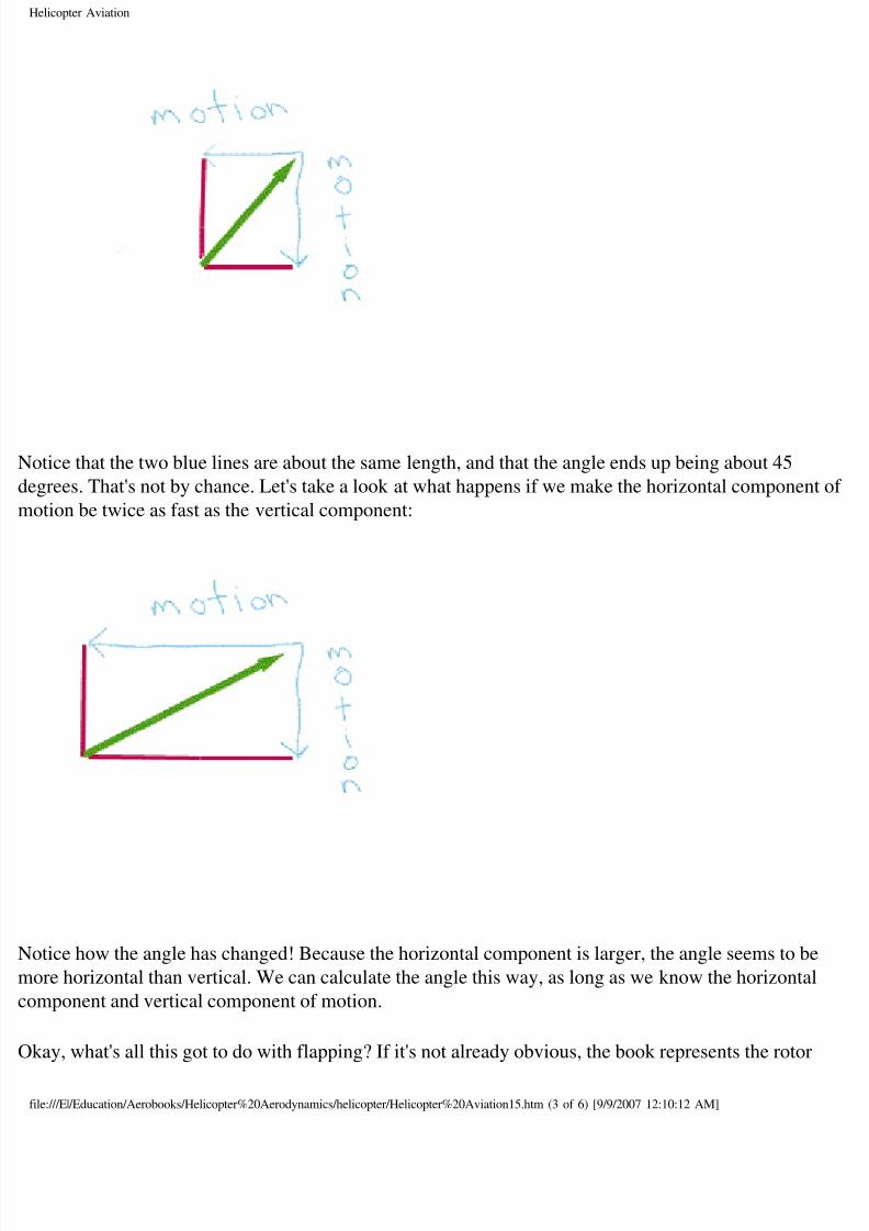
otice that the two blue lines are about the same length, and that the angle ends up being about 45
grees. That's not by chance. Let's take a look at what happens if we make the horizontal componen
otion be twice as fast as the vertical component:
otice how the angle has changed! Because the horizontal component is larger, the angle seems to be
ore horizontal than vertical. We can calculate the angle this way, as long as we know the horizonta
mponent and vertical component of motion.
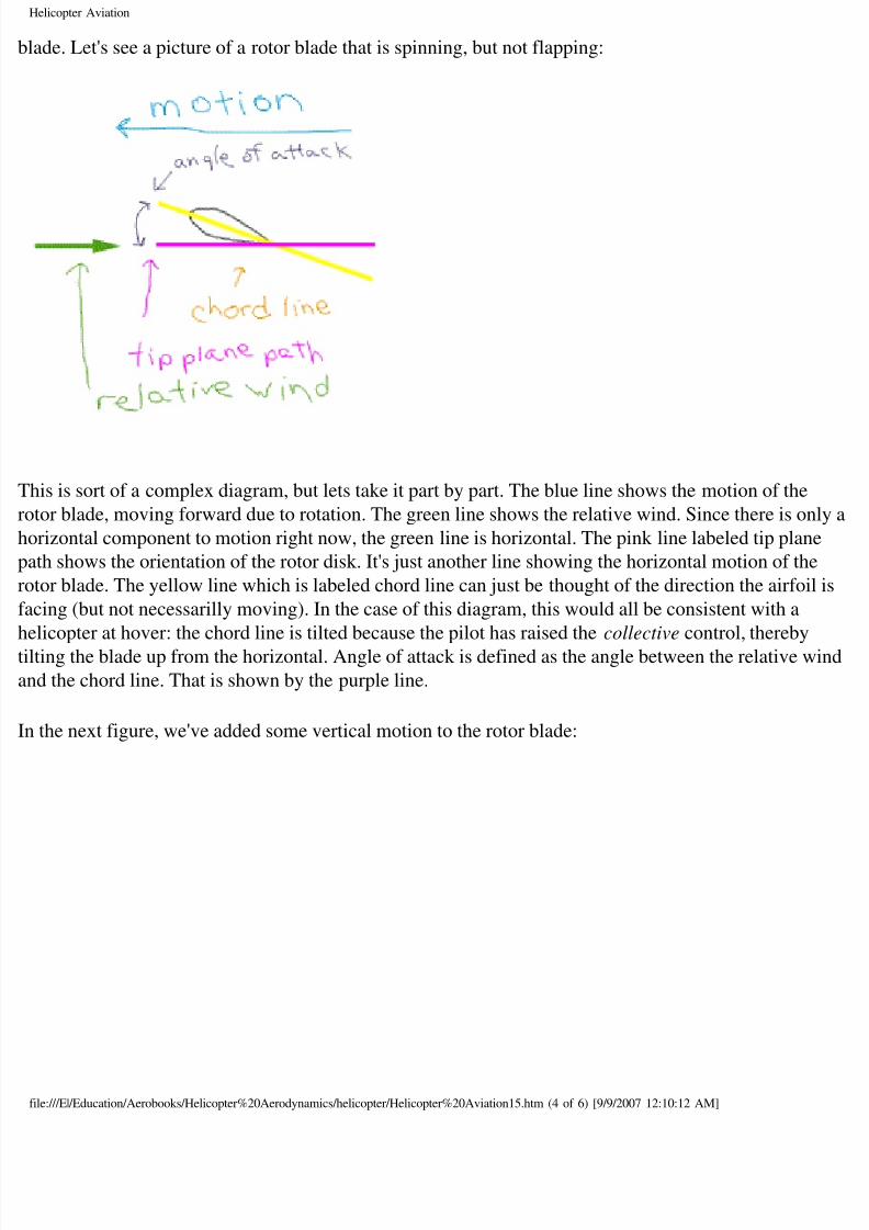
kay, what's all this got to do with flapping? If it's not already obvious, the book represents the rotor
le:///E|/Education/Aerobooks/Helicopter%20Aerodynamics/helicopter/Helicopter%20Aviation15.htm (3 of 6) [9/9/2007 12:10:12 AM]
8/8/2019 Helicopter Fundamentals
http://slidepdf.com/reader/full/helicopter-fundamentals 44/66
Helicopter Aviation
ade. Let's see a picture of a rotor blade that is spinning, but not flapping:
his is sort of a complex diagram, but lets take it part by part. The blue line shows the motion of the
tor blade, moving forward due to rotation. The green line shows the relative wind. Since there is on
orizontal component to motion right now, the green line is horizontal. The pink line labeled tip plan
th shows the orientation of the rotor disk. It's just another line showing the horizontal motion of the
tor blade. The yellow line which is labeled chord line can just be thought of the direction the airfoi
cing (but not necessarilly moving). In the case of this diagram, this would all be consistent with a
licopter at hover: the chord line is tilted because the pilot has raised the collective control, thereby
ting the blade up from the horizontal. Angle of attack is defined as the angle between the relative w
d the chord line. That is shown by the purple line.
the next figure, we've added some vertical motion to the rotor blade:
le:///E|/Education/Aerobooks/Helicopter%20Aerodynamics/helicopter/Helicopter%20Aviation15.htm (4 of 6) [9/9/2007 12:10:12 AM]
8/8/2019 Helicopter Fundamentals
http://slidepdf.com/reader/full/helicopter-fundamentals 45/66
Helicopter Aviation
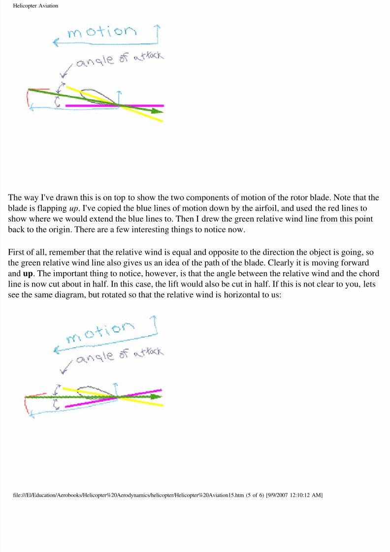
he way I've drawn this is on top to show the two components of motion of the rotor blade. Note tha
ade is flapping up. I've copied the blue lines of motion down by the airfoil, and used the red lines to
ow where we would extend the blue lines to. Then I drew the green relative wind line from this po
ck to the origin. There are a few interesting things to notice now.
rst of all, remember that the relative wind is equal and opposite to the direction the object is going,
e green relative wind line also gives us an idea of the path of the blade. Clearly it is moving forwar
d up. The important thing to notice, however, is that the angle between the relative wind and the ch
ne is now cut about in half. In this case, the lift would also be cut in half. If this is not clear to you,
e the same diagram, but rotated so that the relative wind is horizontal to us:
le:///E|/Education/Aerobooks/Helicopter%20Aerodynamics/helicopter/Helicopter%20Aviation15.htm (5 of 6) [9/9/2007 12:10:12 AM]
8/8/2019 Helicopter Fundamentals
http://slidepdf.com/reader/full/helicopter-fundamentals 46/66
Helicopter Aviation
should be clear that the angle of attack in this picture is much smaller than the diagram without
apping.
ne final key to all this is, what makes the blade flap up? The answer is very simple: it's the excess l
emember that at a hover, the blade angle is where the forces of lift and centrifugal force balance ou
e increase the lift (because of the excess airspeed on the advancing blade) and the centrifugal force
ays the same, the extra lift will cause the blade to flap up to a higher position until lift and centrifugrces are once again in balance.
aul Cantrell
ul at copters.com (replace " at " with "@" to email me - this avoids SPAMMERS I hope)
op] [Up] [Prev] [Next]
le:///E|/Education/Aerobooks/Helicopter%20Aerodynamics/helicopter/Helicopter%20Aviation15.htm (6 of 6) [9/9/2007 12:10:12 AM]
8/8/2019 Helicopter Fundamentals
http://slidepdf.com/reader/full/helicopter-fundamentals 47/66
Helicopter Aviation
op] [Up] [Prev] [Next]
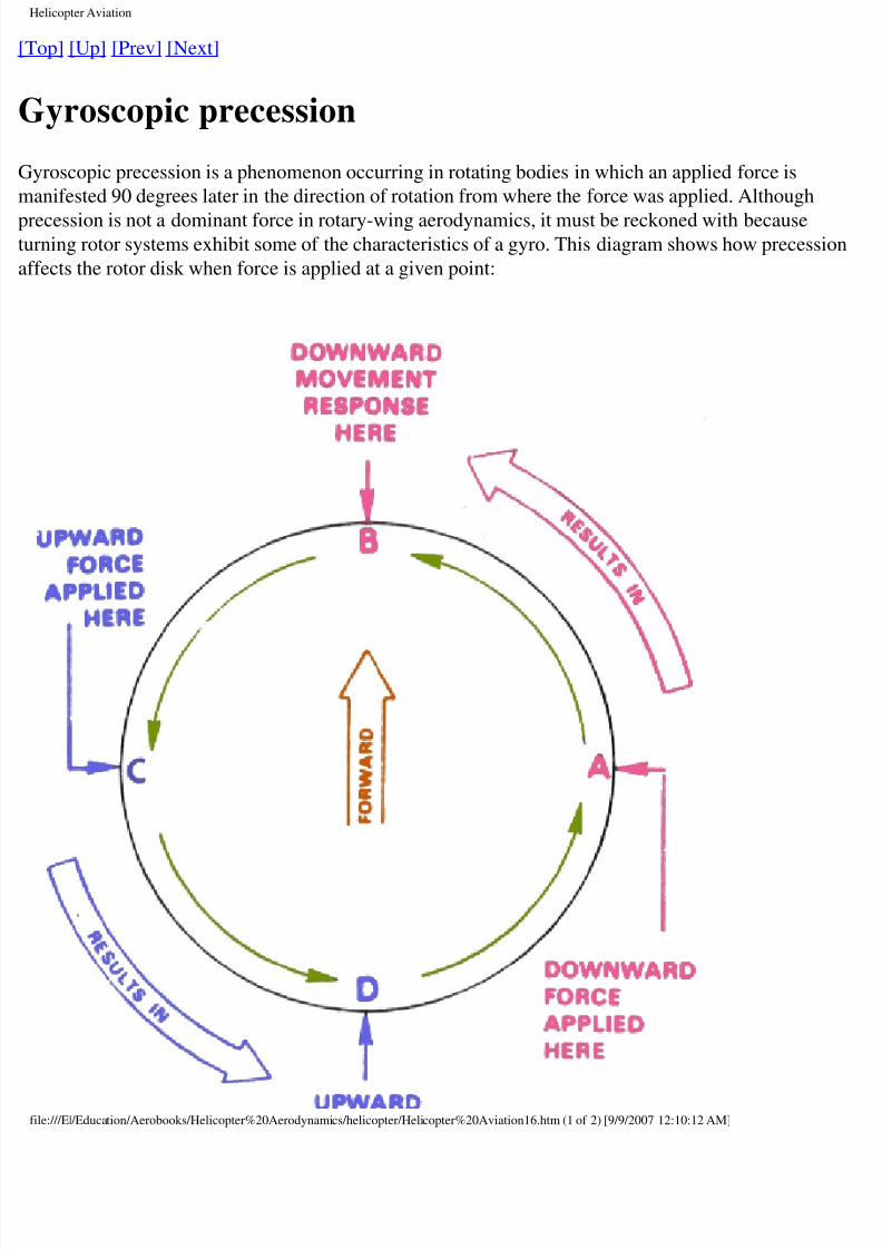
Gyroscopic precession
yroscopic precession is a phenomenon occurring in rotating bodies in which an applied force is
anifested 90 degrees later in the direction of rotation from where the force was applied. Although
ecession is not a dominant force in rotary-wing aerodynamics, it must be reckoned with becauserning rotor systems exhibit some of the characteristics of a gyro. This diagram shows how precessi
fects the rotor disk when force is applied at a given point:
le:///E|/Education/Aerobooks/Helicopter%20Aerodynamics/helicopter/Helicopter%20Aviation16.htm (1 of 2) [9/9/2007 12:10:12 AM]
8/8/2019 Helicopter Fundamentals
http://slidepdf.com/reader/full/helicopter-fundamentals 48/66
Helicopter Aviation
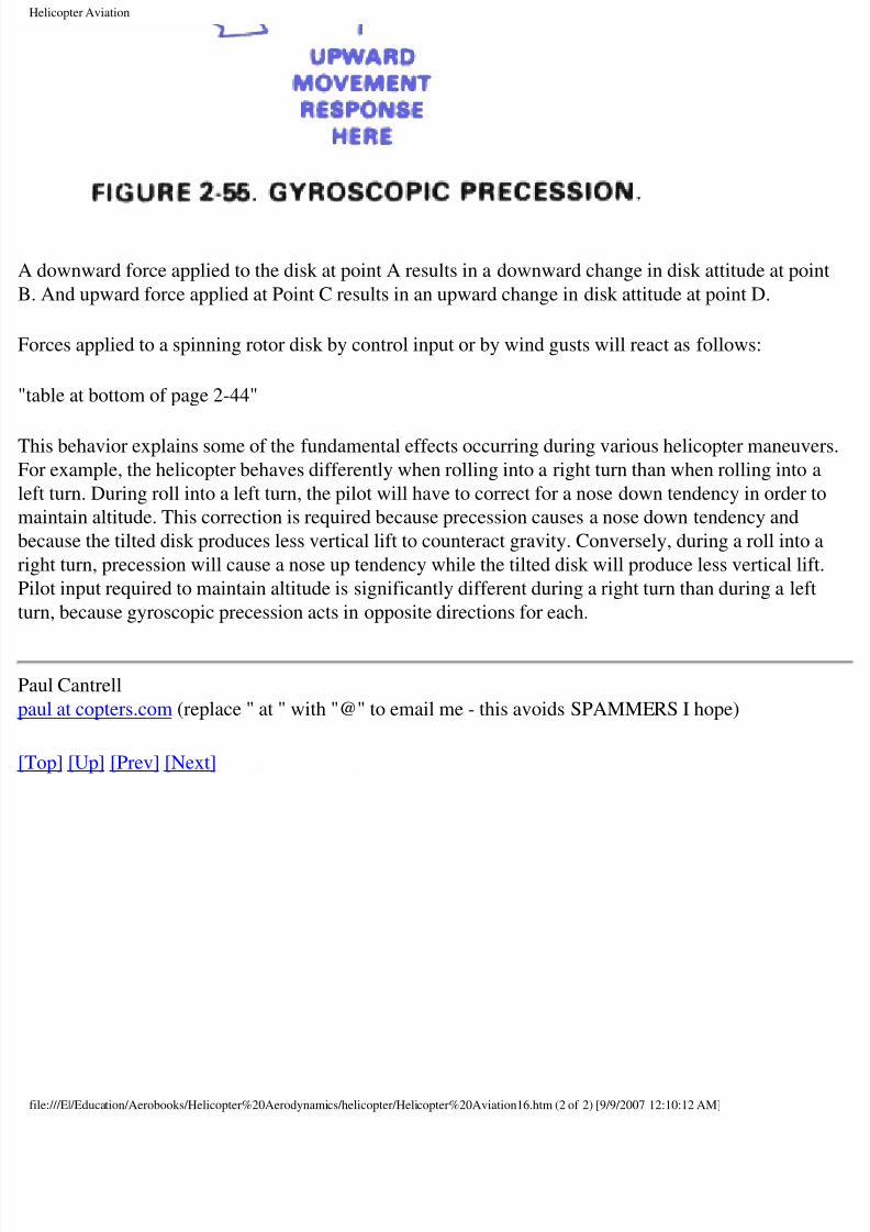
downward force applied to the disk at point A results in a downward change in disk attitude at poi
And upward force applied at Point C results in an upward change in disk attitude at point D.
orces applied to a spinning rotor disk by control input or by wind gusts will react as follows:
able at bottom of page 2-44"
his behavior explains some of the fundamental effects occurring during various helicopter maneuve
or example, the helicopter behaves differently when rolling into a right turn than when rolling into a
ft turn. During roll into a left turn, the pilot will have to correct for a nose down tendency in order t
aintain altitude. This correction is required because precession causes a nose down tendency and
cause the tilted disk produces less vertical lift to counteract gravity. Conversely, during a roll into
ght turn, precession will cause a nose up tendency while the tilted disk will produce less vertical lift
lot input required to maintain altitude is significantly different during a right turn than during a left
rn, because gyroscopic precession acts in opposite directions for each.
aul Cantrell
ul at copters.com (replace " at " with "@" to email me - this avoids SPAMMERS I hope)
op] [Up] [Prev] [Next]
le:///E|/Education/Aerobooks/Helicopter%20Aerodynamics/helicopter/Helicopter%20Aviation16.htm (2 of 2) [9/9/2007 12:10:12 AM]
8/8/2019 Helicopter Fundamentals
http://slidepdf.com/reader/full/helicopter-fundamentals 49/66
Helicopter Aviation
op] [Up] [Prev] [Next]
Retreating Blade Stall
tendency for the retreating blade to stall in forward flight is inherent in all present day helicopters
a major factor in limiting their forward speed. Just as the stall of an airplane wing limits the low sp
ossibilities of the airplane, the stall of a rotor blade limits the high speed potential of a helicopter. Trspeed of the retreating blade (the blade moving away from the direction of flight) slows down as
rward speed increases. The retreating blade must, however, produce an amount of lift equal to that
e advancing blade. Therefore, as the airspeed of the retreating blade decreases with forward aircraf
eed, the blade angle of attack must be increased to equalize lift throughout the rotor disk area. As t
gle increase is continued, the blade will stall at some high forward speed.
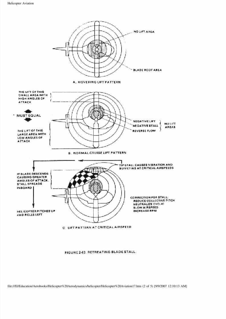
s forward airspeed increases, the "no lift" areas move left of center, covering more of the retreating
ade sectors:
le:///E|/Education/Aerobooks/Helicopter%20Aerodynamics/helicopter/Helicopter%20Aviation17.htm (1 of 5) [9/9/2007 12:10:13 AM]
8/8/2019 Helicopter Fundamentals
http://slidepdf.com/reader/full/helicopter-fundamentals 50/66
Helicopter Aviation
le:///E|/Education/Aerobooks/Helicopter%20Aerodynamics/helicopter/Helicopter%20Aviation17.htm (2 of 5) [9/9/2007 12:10:13 AM]
8/8/2019 Helicopter Fundamentals
http://slidepdf.com/reader/full/helicopter-fundamentals 51/66
Helicopter Aviation
his requires more lift at the outer retreating blade portions to compensate for the loss of lift of the
board retreating sections. In the area of reversed flow, the rotational velocity of this blade section i
ower than the aircraft airspeed; therefore, the air flows from the trailing to leading edge of the airfo
the negative stall area, the rotational velocity of the airfoil is faster than the aircraft airspeed, there
r flows from leading to trailing edge of the blade. However due to the relative arm and induced flow
ade flapping is not sufficient to produce a positive angle of attack. Blade flapping and rotational
locity in the negative lift area are sufficient to produce a positive angle of attack, but not to a degre
at produces appreciable lift.
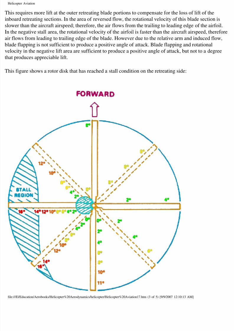
his figure shows a rotor disk that has reached a stall condition on the retreating side:
le:///E|/Education/Aerobooks/Helicopter%20Aerodynamics/helicopter/Helicopter%20Aviation17.htm (3 of 5) [9/9/2007 12:10:13 AM]
8/8/2019 Helicopter Fundamentals
http://slidepdf.com/reader/full/helicopter-fundamentals 52/66
Helicopter Aviation
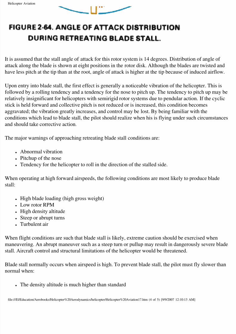
is assumed that the stall angle of attack for this rotor system is 14 degrees. Distribution of angle oftack along the blade is shown at eight positions in the rotor disk. Although the blades are twisted an
ve less pitch at the tip than at the root, angle of attack is higher at the tip because of induced airflow
pon entry into blade stall, the first effect is generally a noticeable vibration of the helicopter. This i
llowed by a rolling tendency and a tendency for the nose to pitch up. The tendency to pitch up may
latively insignificant for helicopters with semirigid rotor systems due to pendular action. If the cycl
ck is held forward and collective pitch is not reduced or is increased, this condition becomes
gravated; the vibration greatly increases, and control may be lost. By being familiar with the
nditions which lead to blade stall, the pilot should realize when his is flying under such circumstand should take corrective action.
he major warnings of approaching retreating blade stall conditions are:
● Abnormal vibration
● Pitchup of the nose
● Tendency for the helicopter to roll in the direction of the stalled side.
hen operating at high forward airspeeds, the following conditions are most likely to produce blade
all:
● High blade loading (high gross weight)
● Low rotor RPM
● High density altitude
● Steep or abrupt turns
● Turbulent air
hen flight conditions are such that blade stall is likely, extreme caution should be exercised when
aneuvering. An abrupt maneuver such as a steep turn or pullup may result in dangerously severe bl
all. Aircraft control and structural limitations of the helicopter would be threatened.
ade stall normally occurs when airspeed is high. To prevent blade stall, the pilot must fly slower th
ormal when:
● The density altitude is much higher than standard
le:///E|/Education/Aerobooks/Helicopter%20Aerodynamics/helicopter/Helicopter%20Aviation17.htm (4 of 5) [9/9/2007 12:10:13 AM]
8/8/2019 Helicopter Fundamentals
http://slidepdf.com/reader/full/helicopter-fundamentals 53/66
Helicopter Aviation
● Carrying maximum weight loads
● Flying high drag configurations such as floats, external stores, weapons, speakers, floodlights
sling loads, etc.
● The air is turbulent
hen the pilot suspects blade stall, he can possibly prevent it from occurring by sequentially:
● Reducing power (collective pitch)● Reducing airspeed
● Reducing "G" loads during manuevering
● Increasing RPM to upper allowable limit
● Checking pedal trim
severe blade stall, the pilot loses control. The helicopter will pitch up violently and roll to the left.
nly corrective action then is to accomplish procedures as indicated previously to shorten the duratio
e stall and regain control.
aul Cantrell
ul at copters.com (replace " at " with "@" to email me - this avoids SPAMMERS I hope)
op] [Up] [Prev] [Next]
le:///E|/Education/Aerobooks/Helicopter%20Aerodynamics/helicopter/Helicopter%20Aviation17.htm (5 of 5) [9/9/2007 12:10:13 AM]
8/8/2019 Helicopter Fundamentals
http://slidepdf.com/reader/full/helicopter-fundamentals 54/66
Helicopter Aviation
op] [Up] [Prev] [Next]
ettling with Power
ttling with Power is a condition of powered flight where the helicopter settles into its own downwa
he condition may also be referred to as the vortex ring state.
onditions conducive to settling with power are a vertical or nearly vertical descent of at least 300 fe
r minute and low forward airspeed. The rotor system must also be using some of the available engi
ower (from 20 to 100 percent) with insufficient power available to retard the sink rate. These
nditions occur during approaches with a tailwind or during formation approaches when some aircr
e flying in turbulence from other aircraft.
nder the conditions described above, the helicopter may descend at a high rate which exceeds the
ormal downward induced flow rate of the inner blade sections. As a result, the airflow of the inner
ade sections is upward relative to the disk. This produces a secondary vortex ring in addition to theormal tip vortex system. The secondary vortex ring is generated about the point on the blade where
rflow changes from up to down. The result is an unsteady turbulent flow over a large area of the dis
hich causes loss of rotor efficiency even though power is still supplied from the engine.
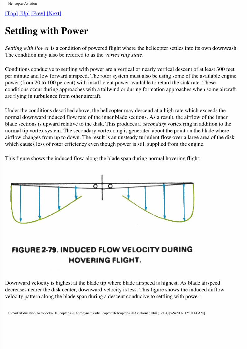
his figure shows the induced flow along the blade span during normal hovering flight:
ownward velocity is highest at the blade tip where blade airspeed is highest. As blade airspeed
creases nearer the disk center, downward velocity is less. This figure shows the induced airflow
locity pattern along the blade span during a descent conducive to settling with power:
le:///E|/Education/Aerobooks/Helicopter%20Aerodynamics/helicopter/Helicopter%20Aviation18.htm (1 of 4) [9/9/2007 12:10:14 AM]
8/8/2019 Helicopter Fundamentals
http://slidepdf.com/reader/full/helicopter-fundamentals 55/66
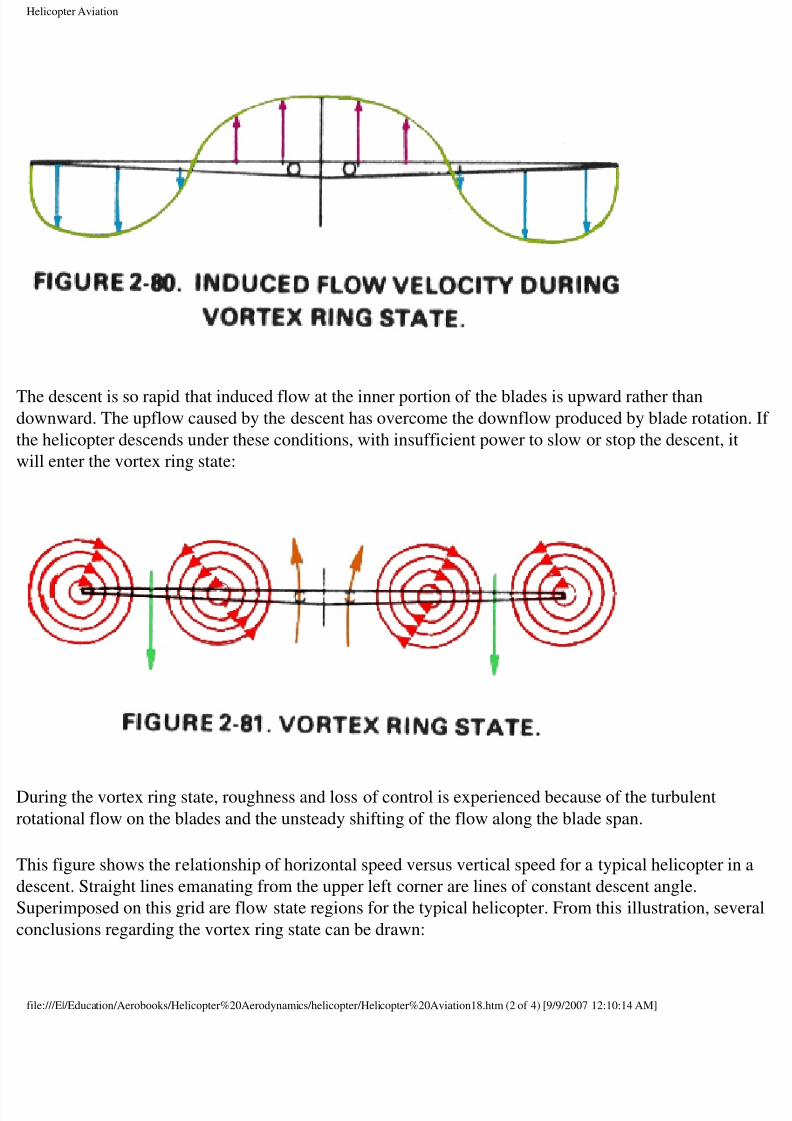
Helicopter Aviation
he descent is so rapid that induced flow at the inner portion of the blades is upward rather thanownward. The upflow caused by the descent has overcome the downflow produced by blade rotatio
e helicopter descends under these conditions, with insufficient power to slow or stop the descent, it
ill enter the vortex ring state:
uring the vortex ring state, roughness and loss of control is experienced because of the turbulent
tational flow on the blades and the unsteady shifting of the flow along the blade span.
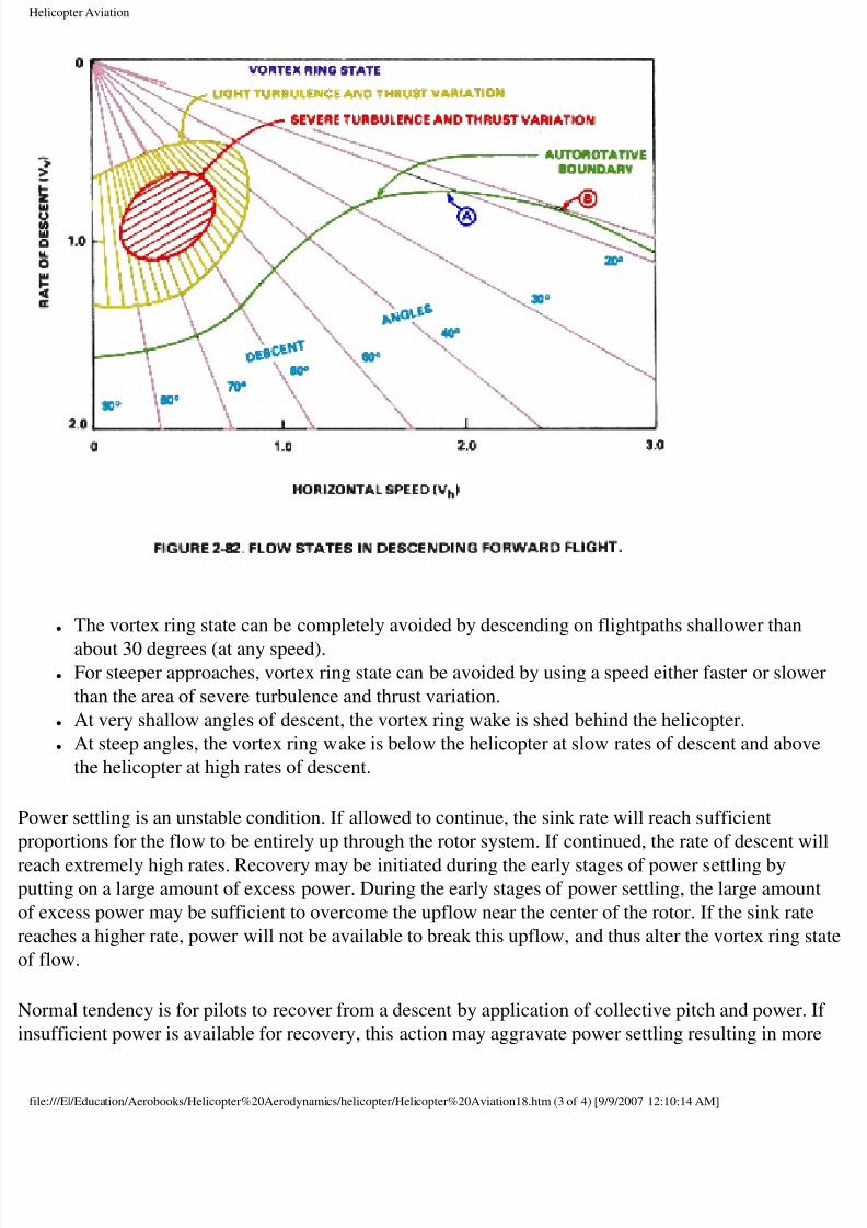
his figure shows the relationship of horizontal speed versus vertical speed for a typical helicopter in
scent. Straight lines emanating from the upper left corner are lines of constant descent angle.
uperimposed on this grid are flow state regions for the typical helicopter. From this illustration, sev
nclusions regarding the vortex ring state can be drawn:
le:///E|/Education/Aerobooks/Helicopter%20Aerodynamics/helicopter/Helicopter%20Aviation18.htm (2 of 4) [9/9/2007 12:10:14 AM]
8/8/2019 Helicopter Fundamentals
http://slidepdf.com/reader/full/helicopter-fundamentals 56/66
Helicopter Aviation
● The vortex ring state can be completely avoided by descending on flightpaths shallower than
about 30 degrees (at any speed).● For steeper approaches, vortex ring state can be avoided by using a speed either faster or slow
than the area of severe turbulence and thrust variation.
● At very shallow angles of descent, the vortex ring wake is shed behind the helicopter.
● At steep angles, the vortex ring wake is below the helicopter at slow rates of descent and abov
the helicopter at high rates of descent.
ower settling is an unstable condition. If allowed to continue, the sink rate will reach sufficient
oportions for the flow to be entirely up through the rotor system. If continued, the rate of descent w
ach extremely high rates. Recovery may be initiated during the early stages of power settling byutting on a large amount of excess power. During the early stages of power settling, the large amoun
excess power may be sufficient to overcome the upflow near the center of the rotor. If the sink rate
aches a higher rate, power will not be available to break this upflow, and thus alter the vortex ring s
flow.
ormal tendency is for pilots to recover from a descent by application of collective pitch and power.
sufficient power is available for recovery, this action may aggravate power settling resulting in mo
le:///E|/Education/Aerobooks/Helicopter%20Aerodynamics/helicopter/Helicopter%20Aviation18.htm (3 of 4) [9/9/2007 12:10:14 AM]

8/8/2019 Helicopter Fundamentals
http://slidepdf.com/reader/full/helicopter-fundamentals 57/66
Helicopter Aviation
rbulence and a higher rate of descent. Recovery can be accomplished by lowering collective pitch a
creasing forward speed. Both of these methods of recovery require altitude to be successful.
aul Cantrell
ul at copters.com (replace " at " with "@" to email me - this avoids SPAMMERS I hope)
op] [Up] [Prev] [Next]
le:///E|/Education/Aerobooks/Helicopter%20Aerodynamics/helicopter/Helicopter%20Aviation18.htm (4 of 4) [9/9/2007 12:10:14 AM]
8/8/2019 Helicopter Fundamentals
http://slidepdf.com/reader/full/helicopter-fundamentals 58/66
Helicopter Aviation
op] [Up] [Prev] [Next]
Aerodynamics of Autorotation
uring powered flight, the rotor drag is overcome with engine power. When the engine fails, or is
liberately disengaged from the rotor system, some other force must be used to sustain rotor RPM s
ntrolled flight can be continued to the ground. This force is generated by adjusting the collective pallow a controlled descent. Airflow during helicopter descent provides the energy to overcome bla
ag and turn the rotor. When the helicopter is descending in this manner, it is said to be in a state of
utorotation. In effect the pilot gives up altitude at a controlled rate in return for energy to turn the ro
an RPM which provides aircraft control. Stated another way, the helicopter has potential energy by
rtue of its altitude. As altitude decreases, potential energy is converted to kinetic energy and stored
e turning rotor. The pilot uses this kinetic energy to cushion the touchdown when near the ground.
ost autorotations are performed with forward airspeed. For simplicity, the following aerodynamic
planation is based on a vertical autorotative descent (no forward airspeed) in still air. Under thesenditions, the forces that cause the blades to turn are similar for all blades regardless of their positio
e plane of rotation. Dissymmetry of lift resulting from helicopter airspeed is therefore not a factor,
ill be discussed later.
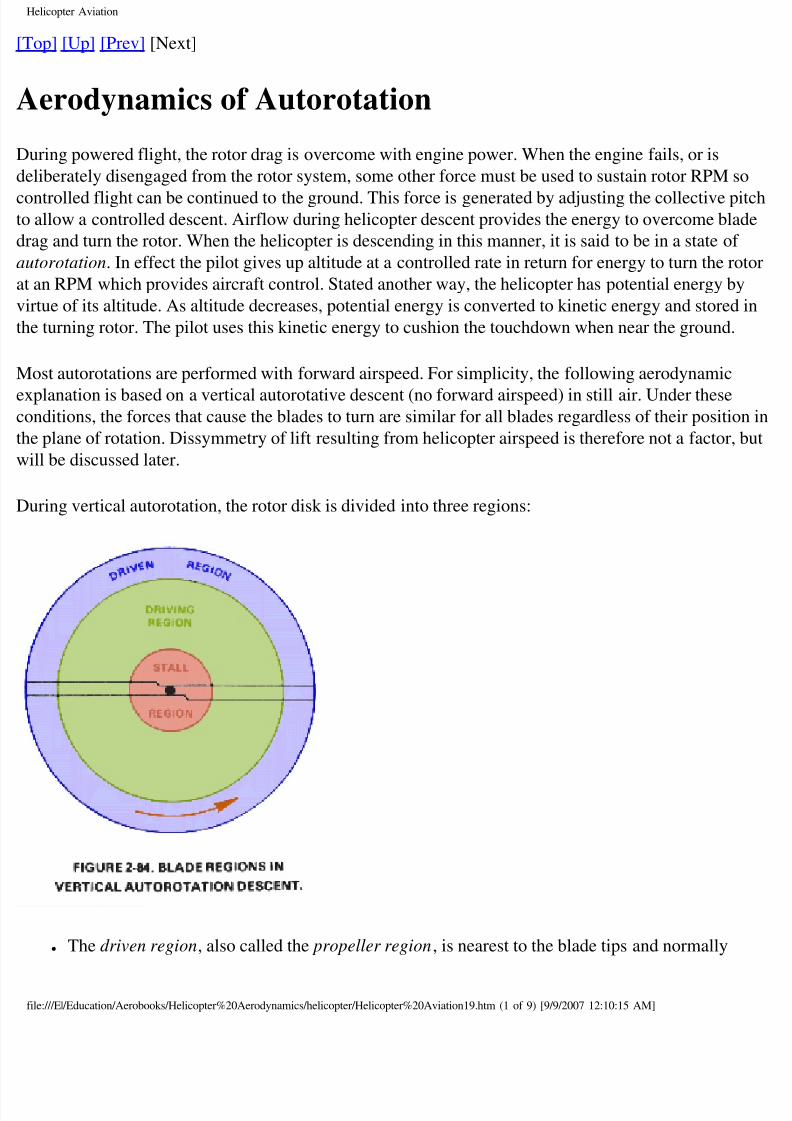
uring vertical autorotation, the rotor disk is divided into three regions:
● The driven region, also called the propeller region, is nearest to the blade tips and normally
le:///E|/Education/Aerobooks/Helicopter%20Aerodynamics/helicopter/Helicopter%20Aviation19.htm (1 of 9) [9/9/2007 12:10:15 AM]
8/8/2019 Helicopter Fundamentals
http://slidepdf.com/reader/full/helicopter-fundamentals 59/66
Helicopter Aviation
consists of about 30 percent of the radius. The total aerodynamic force in this region is incline
slightly behind the rotating axis. This results in a drag force which tends to slow the rotation f
the blade.
● The driving region or autorotative region, normally lies between about 25 to 70 percent of the
blade radius. Total aerodynamic force in this region is inclined slightly forward of the axis of
rotation. This inclination supplies thrust which tends to accelerate the rotation of the blade.
● The stall region includes the inboard 25 percent of the blade radius. It operates above the stall
angle of attack and causes drag which tends to slow the rotation of the blade.
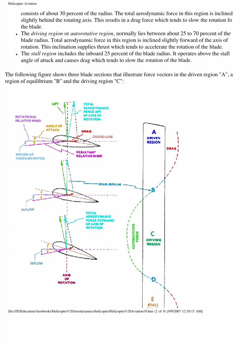
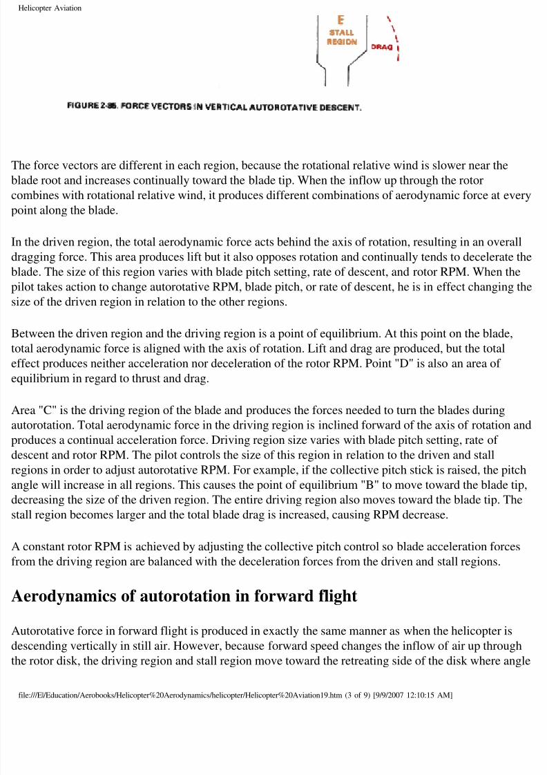
he following figure shows three blade sections that illustrate force vectors in the driven region "A",
gion of equilibrium "B" and the driving region "C":
le:///E|/Education/Aerobooks/Helicopter%20Aerodynamics/helicopter/Helicopter%20Aviation19.htm (2 of 9) [9/9/2007 12:10:15 AM]
8/8/2019 Helicopter Fundamentals
http://slidepdf.com/reader/full/helicopter-fundamentals 60/66
Helicopter Aviation
he force vectors are different in each region, because the rotational relative wind is slower near the
ade root and increases continually toward the blade tip. When the inflow up through the rotor
mbines with rotational relative wind, it produces different combinations of aerodynamic force at ev
oint along the blade.
the driven region, the total aerodynamic force acts behind the axis of rotation, resulting in an over
agging force. This area produces lift but it also opposes rotation and continually tends to decelerate
ade. The size of this region varies with blade pitch setting, rate of descent, and rotor RPM. When thlot takes action to change autorotative RPM, blade pitch, or rate of descent, he is in effect changing
ze of the driven region in relation to the other regions.
etween the driven region and the driving region is a point of equilibrium. At this point on the blade
tal aerodynamic force is aligned with the axis of rotation. Lift and drag are produced, but the total
fect produces neither acceleration nor deceleration of the rotor RPM. Point "D" is also an area of
uilibrium in regard to thrust and drag.
rea "C" is the driving region of the blade and produces the forces needed to turn the blades duringtorotation. Total aerodynamic force in the driving region is inclined forward of the axis of rotation
oduces a continual acceleration force. Driving region size varies with blade pitch setting, rate of
scent and rotor RPM. The pilot controls the size of this region in relation to the driven and stall
gions in order to adjust autorotative RPM. For example, if the collective pitch stick is raised, the pi
gle will increase in all regions. This causes the point of equilibrium "B" to move toward the blade
creasing the size of the driven region. The entire driving region also moves toward the blade tip. T
all region becomes larger and the total blade drag is increased, causing RPM decrease.
constant rotor RPM is achieved by adjusting the collective pitch control so blade acceleration forcom the driving region are balanced with the deceleration forces from the driven and stall regions.
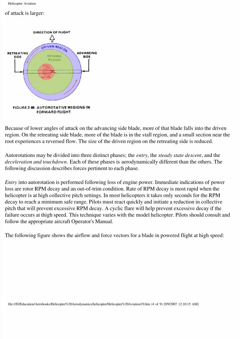
erodynamics of autorotation in forward flight
utorotative force in forward flight is produced in exactly the same manner as when the helicopter is
scending vertically in still air. However, because forward speed changes the inflow of air up throug
e rotor disk, the driving region and stall region move toward the retreating side of the disk where an
le:///E|/Education/Aerobooks/Helicopter%20Aerodynamics/helicopter/Helicopter%20Aviation19.htm (3 of 9) [9/9/2007 12:10:15 AM]
8/8/2019 Helicopter Fundamentals
http://slidepdf.com/reader/full/helicopter-fundamentals 61/66
Helicopter Aviation
attack is larger:
ecause of lower angles of attack on the advancing side blade, more of that blade falls into the drive
gion. On the retreating side blade, more of the blade is in the stall region, and a small section near t
ot experiences a reversed flow. The size of the driven region on the retreating side is reduced.
utorotations may be divided into three distinct phases; the entry, the steady state descent , and the
celeration and touchdown. Each of these phases is aerodynamically different than the others. The
llowing discussion describes forces pertinent to each phase.
ntry into autorotation is performed following loss of engine power. Immediate indications of power
ss are rotor RPM decay and an out-of-trim condition. Rate of RPM decay is most rapid when the
licopter is at high collective pitch settings. In most helicopters it takes only seconds for the RPM
cay to reach a minimum safe range. Pilots must react quickly and initiate a reduction in collective
tch that will prevent excessive RPM decay. A cyclic flare will help prevent excessive decay if the
ilure occurs at thigh speed. This technique varies with the model helicopter. Pilots should consult a
llow the appropriate aircraft Operator's Manual.
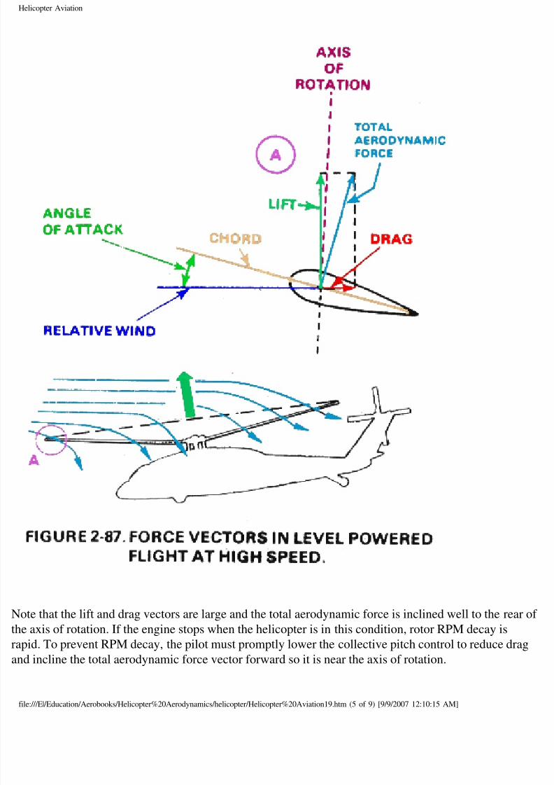
he following figure shows the airflow and force vectors for a blade in powered flight at high speed:
le:///E|/Education/Aerobooks/Helicopter%20Aerodynamics/helicopter/Helicopter%20Aviation19.htm (4 of 9) [9/9/2007 12:10:15 AM]
8/8/2019 Helicopter Fundamentals
http://slidepdf.com/reader/full/helicopter-fundamentals 62/66
Helicopter Aviation
ote that the lift and drag vectors are large and the total aerodynamic force is inclined well to the rea
e axis of rotation. If the engine stops when the helicopter is in this condition, rotor RPM decay is
pid. To prevent RPM decay, the pilot must promptly lower the collective pitch control to reduce dr
d incline the total aerodynamic force vector forward so it is near the axis of rotation.
le:///E|/Education/Aerobooks/Helicopter%20Aerodynamics/helicopter/Helicopter%20Aviation19.htm (5 of 9) [9/9/2007 12:10:15 AM]
8/8/2019 Helicopter Fundamentals
http://slidepdf.com/reader/full/helicopter-fundamentals 63/66
Helicopter Aviation
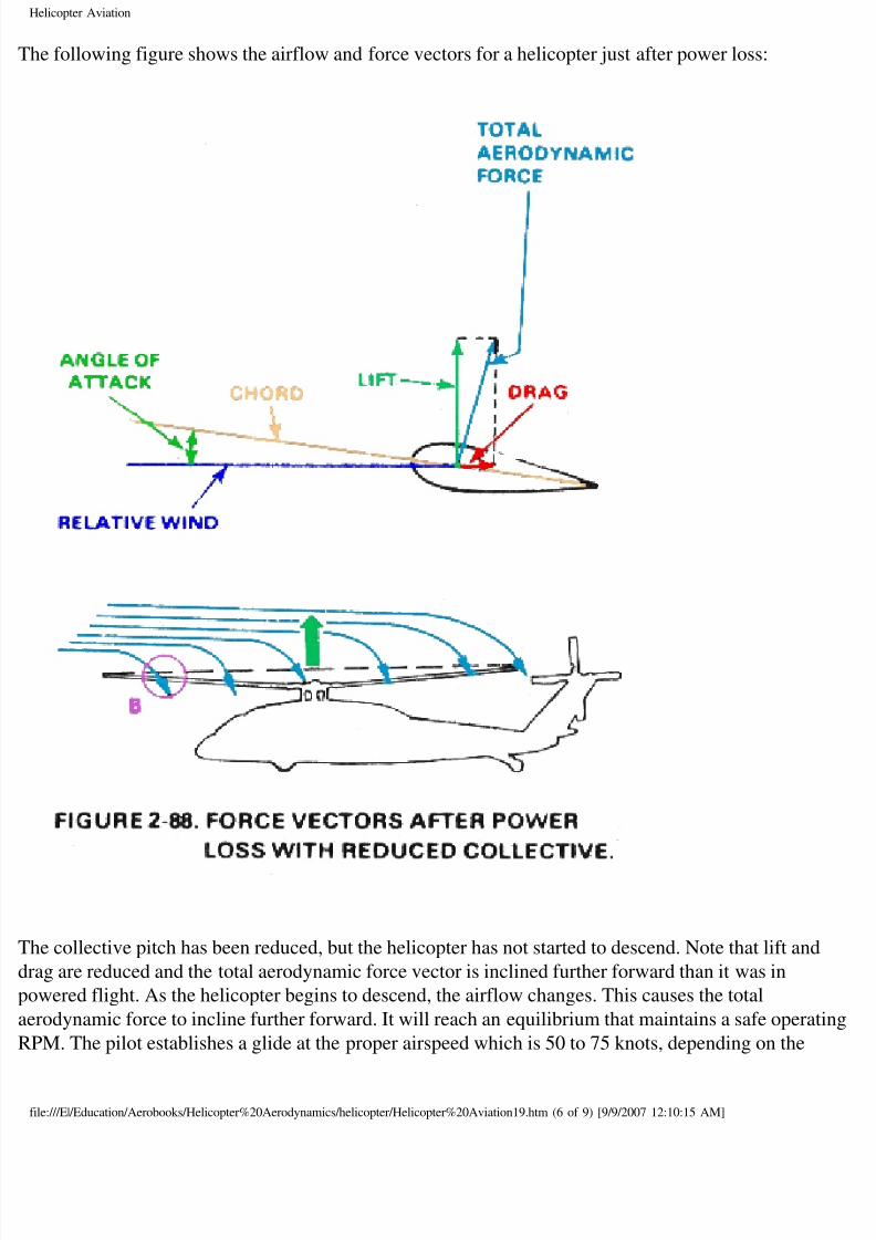
he following figure shows the airflow and force vectors for a helicopter just after power loss:
he collective pitch has been reduced, but the helicopter has not started to descend. Note that lift and
ag are reduced and the total aerodynamic force vector is inclined further forward than it was in
owered flight. As the helicopter begins to descend, the airflow changes. This causes the total
rodynamic force to incline further forward. It will reach an equilibrium that maintains a safe operat
PM. The pilot establishes a glide at the proper airspeed which is 50 to 75 knots, depending on the
le:///E|/Education/Aerobooks/Helicopter%20Aerodynamics/helicopter/Helicopter%20Aviation19.htm (6 of 9) [9/9/2007 12:10:15 AM]
8/8/2019 Helicopter Fundamentals
http://slidepdf.com/reader/full/helicopter-fundamentals 64/66
Helicopter Aviation
licopter and its gross weight. Rotor RPM should be stabilized at autorotative RPM which is norma
few turns higher than normal operating RPM.
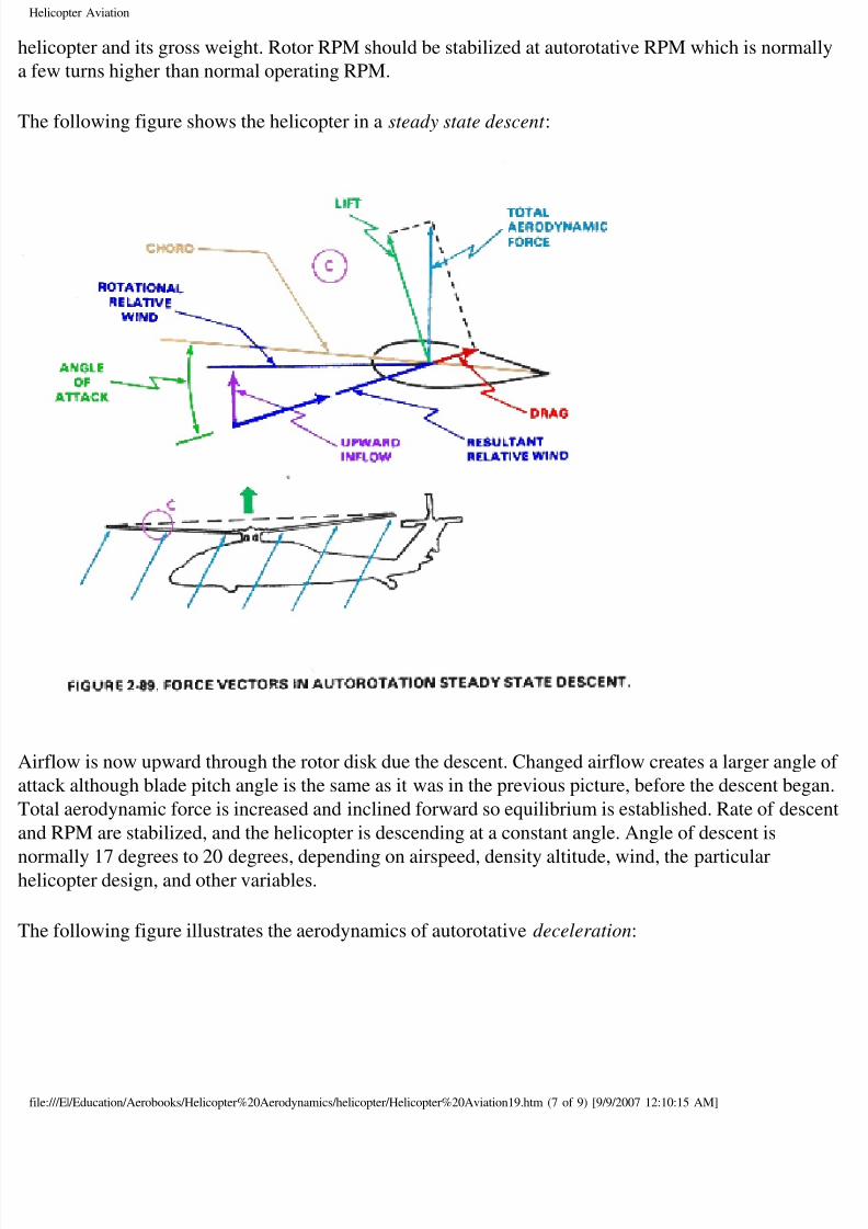
he following figure shows the helicopter in a steady state descent :
irflow is now upward through the rotor disk due the descent. Changed airflow creates a larger angle
tack although blade pitch angle is the same as it was in the previous picture, before the descent beg
otal aerodynamic force is increased and inclined forward so equilibrium is established. Rate of desc
d RPM are stabilized, and the helicopter is descending at a constant angle. Angle of descent is
ormally 17 degrees to 20 degrees, depending on airspeed, density altitude, wind, the particularlicopter design, and other variables.
he following figure illustrates the aerodynamics of autorotative deceleration:
le:///E|/Education/Aerobooks/Helicopter%20Aerodynamics/helicopter/Helicopter%20Aviation19.htm (7 of 9) [9/9/2007 12:10:15 AM]
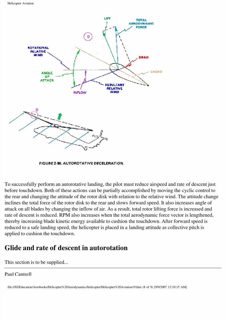
8/8/2019 Helicopter Fundamentals
http://slidepdf.com/reader/full/helicopter-fundamentals 65/66
Helicopter Aviation
o successfully perform an autorotative landing, the pilot must reduce airspeed and rate of descent ju
fore touchdown. Both of these actions can be partially accomplished by moving the cyclic control
e rear and changing the attitude of the rotor disk with relation to the relative wind. The attitude cha
clines the total force of the rotor disk to the rear and slows forward speed. It also increases angle of
tack on all blades by changing the inflow of air. As a result, total rotor lifting force is increased and
te of descent is reduced. RPM also increases when the total aerodynamic force vector is lengthened
ereby increasing blade kinetic energy available to cushion the touchdown. After forward speed is
duced to a safe landing speed, the helicopter is placed in a landing attitude as collective pitch is
plied to cushion the touchdown.
Glide and rate of descent in autorotation
his section is to be supplied...
aul Cantrell
le:///E|/Education/Aerobooks/Helicopter%20Aerodynamics/helicopter/Helicopter%20Aviation19.htm (8 of 9) [9/9/2007 12:10:15 AM]

8/8/2019 Helicopter Fundamentals
http://slidepdf.com/reader/full/helicopter-fundamentals 66/66
Helicopter Aviation
ul at copters.com (replace " at " with "@" to email me - this avoids SPAMMERS I hope)
op] [Up] [Prev] [Next]