Embed Size (px)
Citation preview
HELICOPTER CONTROL USING THE VICON MOTION
CAPTURE SYSTEM
GEORGIA INSTITUTE OF TECHNOLOGY
NOAH ALLENKUNAL AMARNANI
22 OCTOBER 2008

Project Overview
Aerospace department Vicon motion capture system
Automated helicopter control Current position read by motion capture
system Eliminate human error Total implementation cost
~$25,000
Technical Objectives
Read raw current location coordinates from motion capture system
Compare current location and predefined flight path
Calculate necessary flight maneuver Output to helicopter remote control
through parallel port
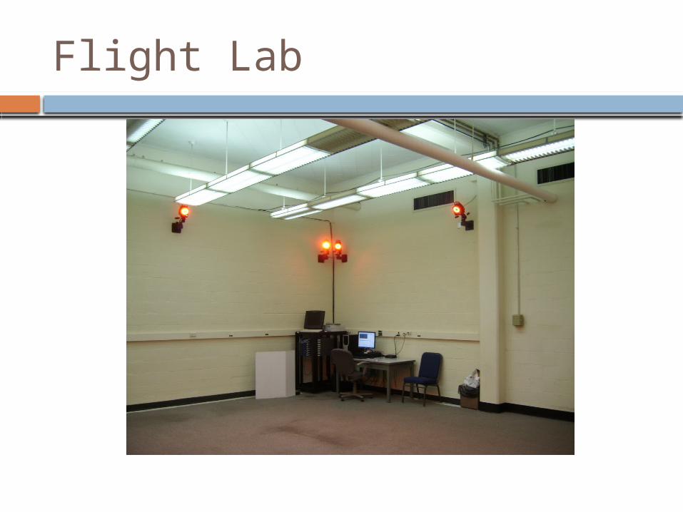
Flight Lab
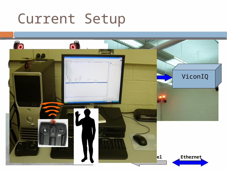
Current Setup
ViconIQ
EthernetParallel
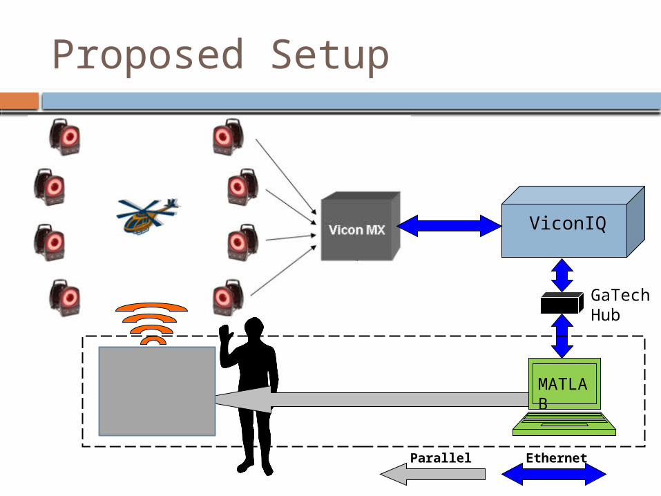
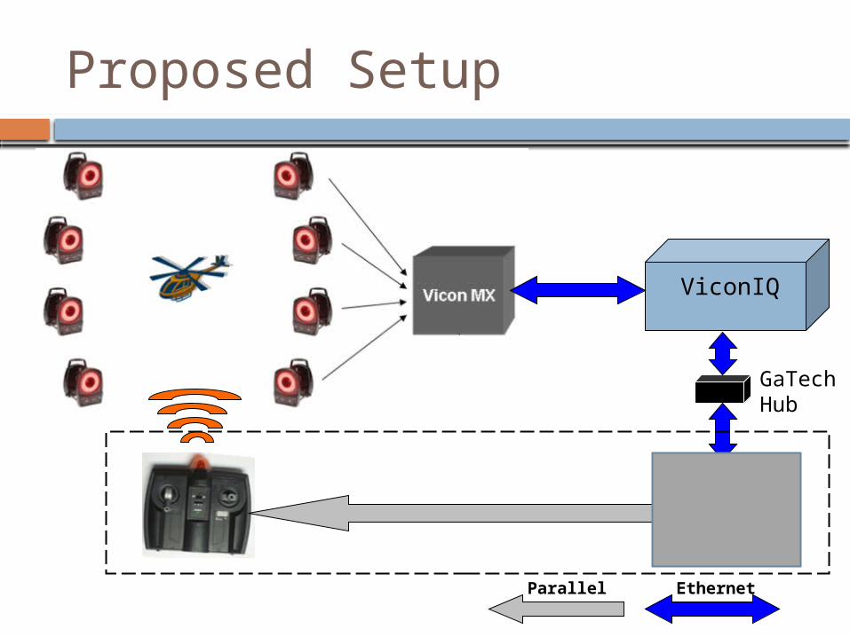
Proposed Setup
ViconIQ
EthernetParallel
MATLAB
GaTech Hub
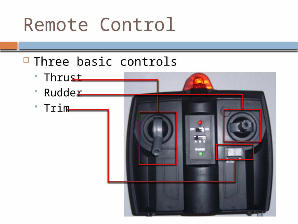
Remote Control
Three basic controls Thrust Rudder Trim

Throttle/Rudder Switch
Digital switches turned on or off due to position of stick
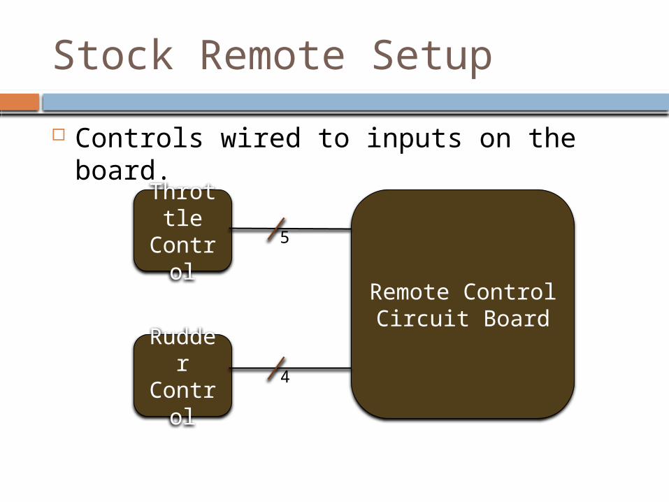
Stock Remote Setup
Controls wired to inputs on the board.
Throttle
Control
Rudder
Control
Remote Control Circuit Board
5
4

Modified Setup
Disconnected controls from board Wired parallel port to the board inputs Wired controls to parallel port cable
Throttle
Control
Rudder
Control
Remote Control Circuit Board
Parallel Port
Parallel Port Cable
5
4
5
4
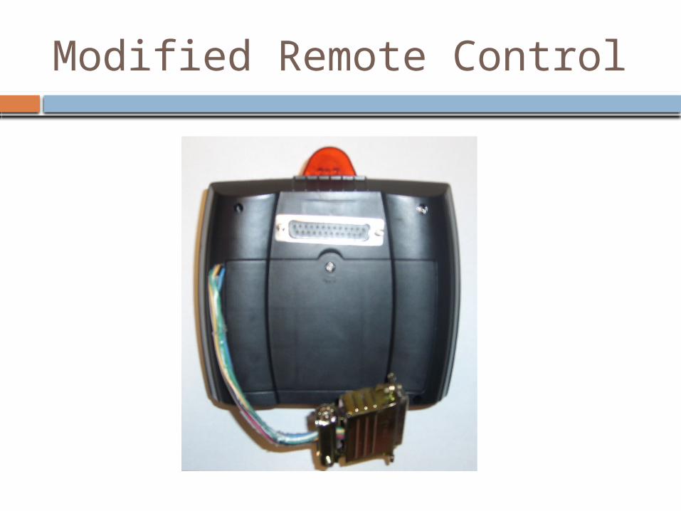
Modified Remote Control
Proposed Setup
ViconIQ
EthernetParallel
MATLAB
GaTech Hub
10010011011101000011111101010010
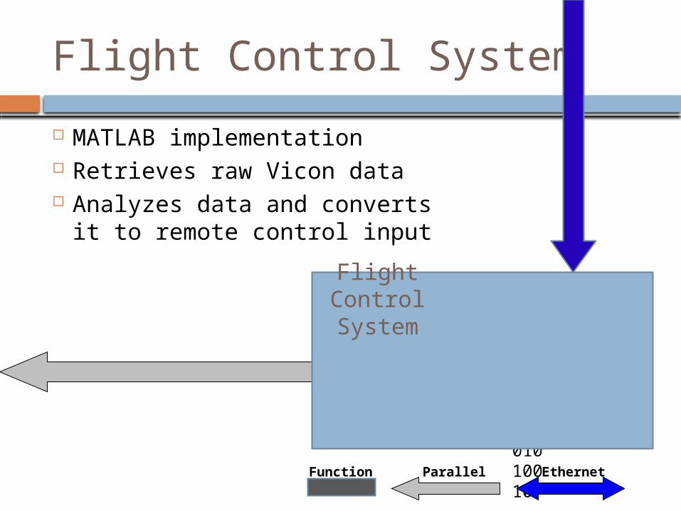
Flight Control System
EthernetParallel
Flight Control System
MATLAB implementation Retrieves raw Vicon data Analyzes data and converts
it to remote control input
Function
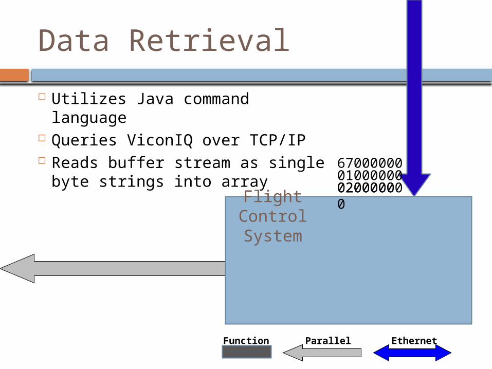
Data Retrieval
EthernetParallel
Utilizes Java command language
Queries ViconIQ over TCP/IP Reads buffer stream as single
byte strings into arrayFlight Control System
020000000200000001000000
67000000
Function

Data Decoding
EthernetParallel
Data comes in as two byte array Array is segmented and converted
to either a double or ASCII characters
Data is recorded into a cell structureFlight
Control System 3
E58
3C72
65
6B
72
61
4D< X >
M A R K E R
Data Analysis Function Function

Data Analysis
EthernetParallel
Implements proportional control flow
Examines error between current location and next location
Scales output amplitude based on gain and error
Flight Control System
Function
Data Analysis Function
Gain Control
System Output
Flight Path

Parallel Output
EthernetParallel
MATLAB capable of accessing parallel port directly
8 bit output will control throttle and rudder speed
Administrative access is necessary
Flight Control System
1001110
Parallel Output
FunctionFunction
Data Analysis Function

Parallel Port
D0-D7 are data lines (bi-directional) C0-C3 are control lines (out) S3-S7 are status lines(in) Pins 18-25 are ground
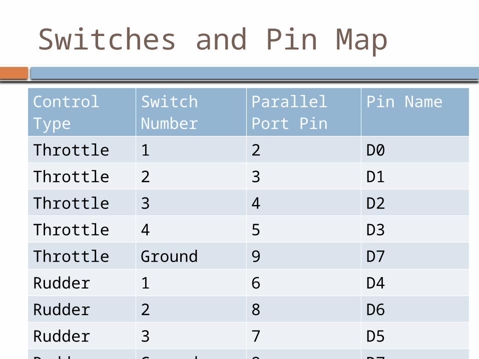
Switches and Pin Map
Control Type
Switch Number
Parallel Port Pin
Pin Name
Throttle 1 2 D0
Throttle 2 3 D1
Throttle 3 4 D2
Throttle 4 5 D3
Throttle Ground 9 D7
Rudder 1 6 D4
Rudder 2 8 D6
Rudder 3 7 D5
Rudder Ground 9 D7
Parallel Port Output
MATLAB capable of accessing parallel port directly.
Writing out 8 bits. 8 bits will control which switch is turned
on or off
Demonstration Plan
Output current location of helicopter using MATLAB GUI
Control helicopter using MATLAB program
Fly a predetermined data path with minimum error
Problems or Issues
Discovering which switches on the control board control what level of output.
Matching ViconIQ system real-time output protocol
Remaining Tasks
Current position value decoding (Oct. 24th)
Current position MATLAB GUI (Oct. 24th) Parallel port voltage map (Oct. 26th) Proportional control system coding (Oct.
26th) Control of helicopter from computer.
(Oct. 29th) Control system to maneuver helicopter
(Nov. 12th)

Budget
Total Equimpent Cost = $0. Total Labor Cost = $10,000
Current Status
Complete Remote Control Modification Tested Parallel port output from MATLAB Written MATLAB code for marker
decoding Analyzing data packets from emulator so
that value decoding can be solved