Embed Size (px)
Citation preview
Hanover Displays Inc., 1601 Tonne Road, Elk Grove Village, IL, 60007 T: +1 (773) 334-9934 1-540667-3
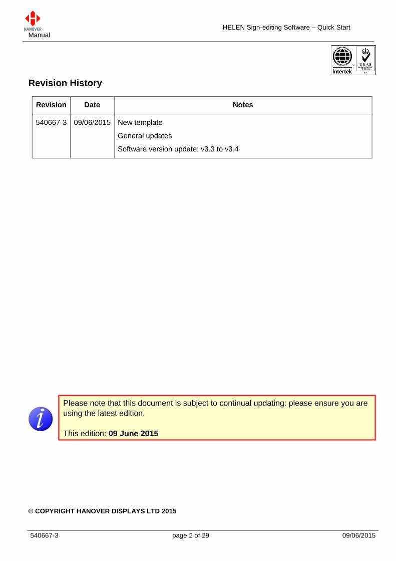
HELEN Sign-editing Software Quick Start Manual (Software version V3.4)
HELEN Sign-editing Software – Quick Start Manual
540667-3 page 2 of 29 09/06/2015
Revision History
Revision Date Notes
540667-3 09/06/2015 New template
General updates
Software version update: v3.3 to v3.4
© COPYRIGHT HANOVER DISPLAYS LTD 2015
Please note that this document is subject to continual updating: please ensure you are
using the latest edition.
This edition: 09 June 2015

HELEN Sign-editing Software – Quick Start Manual
540667-3 page 3 of 29 09/06/2015
The copyright of this document is vested in Hanover Displays Ltd and the document is issued in confidence for the purpose only for which it is supplied. It must not be reproduced in whole or in part or used for tendering or manufacturing purposes except under an agreement or with the consent in writing of Hanover Displays Ltd and then only on the condition that this notice is included in any such reproduction. All trademarks are recognised.
HELEN Sign-editing Software – Quick Start Manual
540667-3 page 4 of 29 09/06/2015
CONTENTS
Preparation 6
Installation from Hanover Resource CD 6
Helen Setup Wizard – From website link or Hanover resource CD 7
Signs 10
Sign Size and Address 11
1st method: From the Controller – Sign Test 11
2.2.1.1 DERIC+ or DG3 11
2.2.1.2 ERIC++ or EG3 12
2nd method: Silver Label and Sign Processor 13
2.2.2.1 From the silver label: sign size 13
2.2.2.2 From the sign processor: sign address 15
Creating a new list 16
Sign Parameter Editor 17
Creating new destinations 19
Inputting the destination code 20
Entering the sign information 20
Saving the destination information 21
Deleting an existing destination 22
For DERIC+ or ERIC++ 23
Transferring destination list to Key-lo 23
Key-lo loading to a DERIC+ or ERIC++ controller 24
For DG3 or EG3 26
Configuring the USB stick for loading 26
Transferring the database to the USB stick using Helen 27
Transferring the database from the USB stick to the DG3 or EG3 28
United Kingdom 29
United States of America 29
HELEN Sign-editing Software – Quick Start Manual
540667-3 page 5 of 29 09/06/2015
GLOSSARY
Explanations relate to the use of the word in this manual and other Hanover publications; the word or
phrase may have other meanings elsewhere.
console - former term for ‘controller’
(sign or driver) controller - on-bus device used by driver to select destination / advert / information details
that will be shown on the signs (prepared using Helen software)
destination code - the number used to identify a particular set of destination signs (typically, front, side
and rear signs). NOT necessarily the operator's route / service number
display - equipment used to present text and graphics for viewing by passengers, usually located on the
front, side or rear of, or inside, a bus
Key-lo - device used to transfer a Helen database from a pc to a Deric+ or Eric++ controller
LED - Light-Emitting Diode
mimic - a tool within Helen which gives a representation of how the sign will appear on the bus
sign - display
HELEN Sign-editing Software – Quick Start Manual
540667-3 page 6 of 29 09/06/2015
Installation
Preparation
Before beginning the installation, for which administrator’s rights will be required:
close down all other programs
back up any existing destination lists to another location on the computer
uninstall any existing versions of Helen installed on the computer, otherwise database errors may
occur
Helen software v3.4 can be installed on the PC:
Either from the website link (www.hanoverdisplays.com), click on the “HELEN Sign Editing
Software” icon ( ) to download the installer. You will then have to register yourself in order
to be given access to your account.
Or from the “Hanover Resource CD” to insert into your CD-ROM drive.
Or from the link supplied by Hanover Technical Support.
Installation from Hanover Resource CD
Step Description Figure
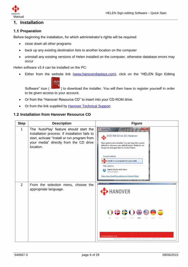
1 The ‘AutoPlay’ feature should start the
installation process. If installation fails to
start, activate “Install or run program from
your media” directly from the CD drive
location.
2 From the selection menu, choose the
appropriate language.
HELEN Sign-editing Software – Quick Start Manual
540667-3 page 7 of 29 09/06/2015
Helen Setup Wizard – From website link or Hanover resource CD
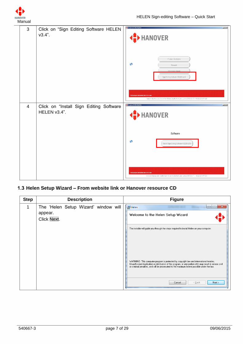
3 Click on “Sign Editing Software HELEN
v3.4”.
4 Click on “Install Sign Editing Software
HELEN v3.4”.
Step Description Figure
1 The ‘Helen Setup Wizard’ window will
appear.
Click Next.
HELEN Sign-editing Software – Quick Start Manual
540667-3 page 8 of 29 09/06/2015
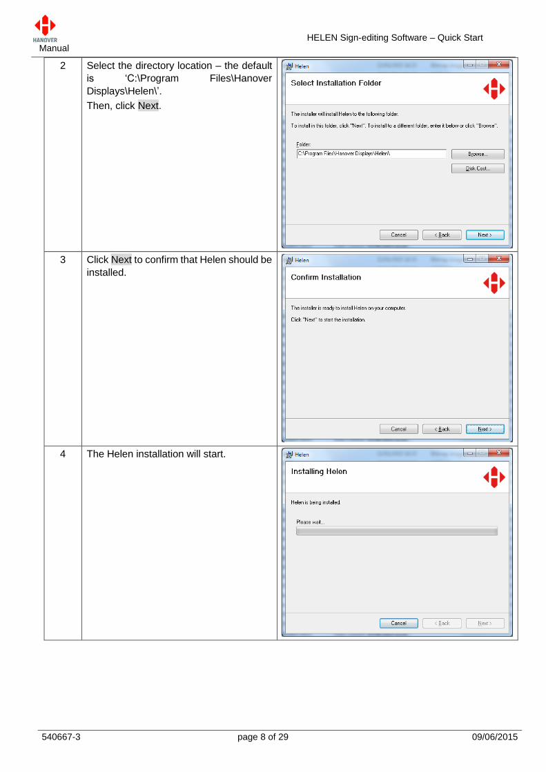
2 Select the directory location – the default
is ‘C:\Program Files\Hanover
Displays\Helen\’.
Then, click Next.
3 Click Next to confirm that Helen should be
installed.
4 The Helen installation will start.
HELEN Sign-editing Software – Quick Start Manual
540667-3 page 9 of 29 09/06/2015
Note: If a Key-lo is being used, the Key-lo drivers must be installed first. Select All Programs Hanover Displays Install Keylo Drivers and follow the wizard. For more information, please refer to Key-lo – Installation and Operation Guide (ref. 540039).
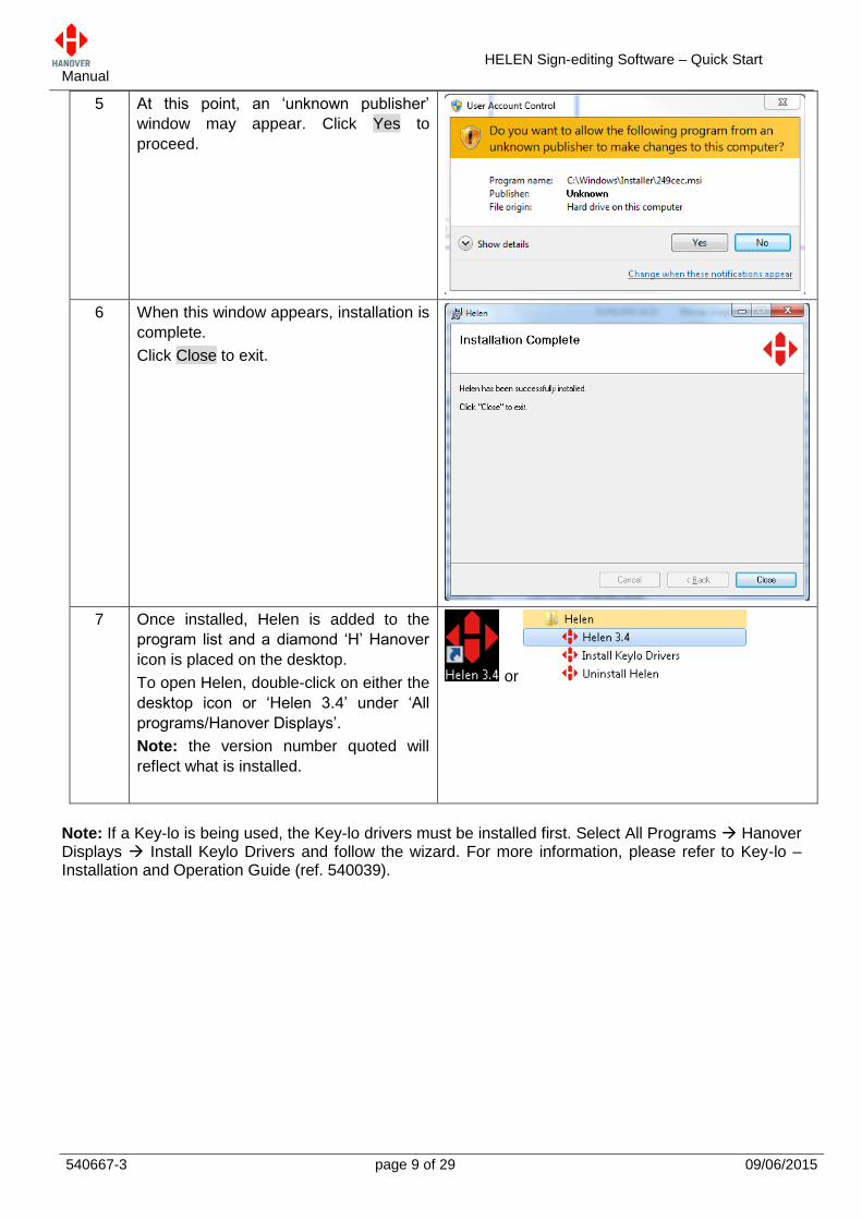
5 At this point, an ‘unknown publisher’
window may appear. Click Yes to
proceed.
6 When this window appears, installation is
complete.
Click Close to exit.
7 Once installed, Helen is added to the
program list and a diamond ‘H’ Hanover
icon is placed on the desktop.
To open Helen, double-click on either the
desktop icon or ‘Helen 3.4’ under ‘All
programs/Hanover Displays’.
Note: the version number quoted will
reflect what is installed.
or
HELEN Sign-editing Software – Quick Start Manual
540667-3 page 10 of 29 09/06/2015
Getting Started
Signs
All Hanover sign types can be programmed by Helen. However, certain information will be required before
a destination list database can be created:
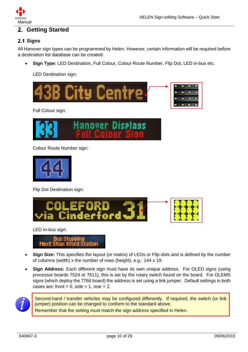
Sign Type: LED Destination, Full Colour, Colour Route Number, Flip Dot, LED in-bus etc.
LED Destination sign:
Full Colour sign:
Colour Route Number sign:
Flip Dot Destination sign:
LED In-bus sign:
Sign Size: This specifies the layout (or matrix) of LEDs or Flip-dots and is defined by the number
of columns (width) x the number of rows (height), e.g.: 144 x 19.
Sign Address: Each different sign must have its own unique address. For OLED signs (using
processor boards 7524 or 7611), this is set by the rotary switch found on the board. For OLEMS
signs (which deploy the 7766 board) the address is set using a link jumper. Default settings in both
cases are: front = 0, side = 1, rear = 2.
Second-hand / transfer vehicles may be configured differently. If required, the switch (or link jumper) position can be changed to conform to the standard above.
Remember that the setting must match the sign address specified in Helen.
HELEN Sign-editing Software – Quick Start Manual
540667-3 page 11 of 29 09/06/2015
Sign Size and Address
There are two methods to provide the sign size and address:
either via the sign test from the controller (for LED sign systems only)
or via the silver label (for size) and sign processor (for address).
The user may find it helpful to keep a record of the sign size and product number of each sign installed for
reference: it will help if advice from 6 Hanover Technical Support is necessary later.
1st method: From the Controller – Sign Test
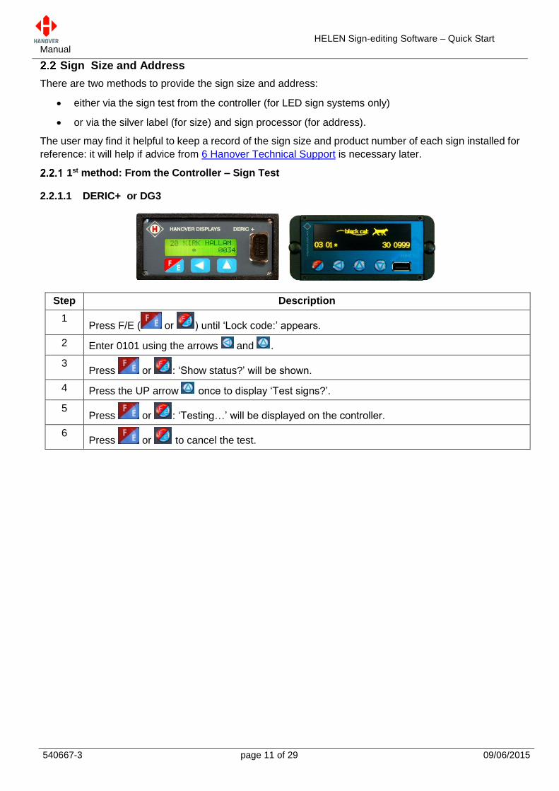
2.2.1.1 DERIC+ or DG3
Step Description
1 Press F/E ( or ) until ‘Lock code:’ appears.
2 Enter 0101 using the arrows and .
3 Press or : ‘Show status?’ will be shown.
4 Press the UP arrow once to display ‘Test signs?’.
5 Press or : ‘Testing…’ will be displayed on the controller.
6 Press or to cancel the test.
HELEN Sign-editing Software – Quick Start Manual
540667-3 page 12 of 29 09/06/2015
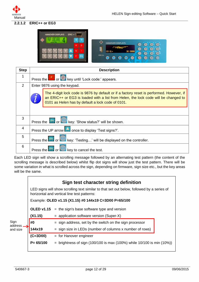
2.2.1.2 ERIC++ or EG3
Each LED sign will show a scrolling message followed by an alternating test pattern (the content of the
scrolling message is described below) whilst flip dot signs will show just the test pattern. There will be
some variation in what is scrolled across the sign, depending on firmware, sign size etc., but the key areas
will be the same.
Step Description
1 Press the or key until ‘Lock code:’ appears.
2 Enter 9876 using the keypad.
3 Press the or key: ‘Show status?’ will be shown.
4 Press the UP arrow once to display ‘Test signs?’.
5 Press the or key: ‘Testing…’ will be displayed on the controller.
6 Press the or key to cancel the test.
Sign test character string definition
LED signs will show scrolling text similar to that set out below, followed by a series of
horizontal and vertical line test patterns:
Example: OLED v1.15 (X1.15) #0 144x19 C=3D00 P=65/100
OLED v1.15 = the sign's base software type and version
(X1.15) = application software version (Super-X)
#0 = sign address, set by the switch on the sign processor
144x19 = sign size in LEDs (number of columns x number of rows)
(C=3D00) = for Hanover engineer
P= 65/100 = brightness of sign (100/100 is max (100%) while 10/100 is min (10%))
The 4-digit lock code is 9876 by default or if a factory reset is performed. However, if
an ERIC++ or EG3 is loaded with a list from Helen, the lock code will be changed to
0101 as Helen has by default a lock code of 0101.
Sign address and size
HELEN Sign-editing Software – Quick Start Manual
540667-3 page 13 of 29 09/06/2015
2nd method: Silver Label and Sign Processor
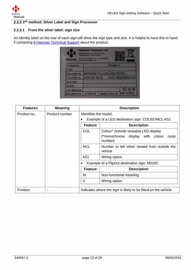
2.2.2.1 From the silver label: sign size
An identity label on the rear of each sign will show the sign type and size. It is helpful to have this to hand
if contacting 6 Hanover Technical Support about the product.
Features Meaning Description
Product no. Product number Identifies the model.
Example of a LED destination sign: COL037MCL-K51
Feature Description
COL Colour* Outside viewable LED display
(*monochrome display with colour route
number)
MCL Number to left when viewed from outside the
vehicle
K51 Wiring option
Example of a FlipDot destination sign: M018C
Feature Description
M Non-functional meaning
C Wiring option
Position - Indicates where the sign is likely to be fitted on the vehicle.
HELEN Sign-editing Software – Quick Start Manual
540667-3 page 14 of 29 09/06/2015
Type - Example of a LED destination sign: 200*24 M\COLOUR
LHS R\NO. ‘K51’
Feature Description
200*24 Size of sign
M\COLOUR Multi-Colour
LHS Left-Hand Side
R\NO. Route Number
K51 Wiring option
Example of a FlipDot destination sign: 96*16-4L SIGN ‘C’
Feature Description
96*16 Size of sign
4L 4” Length (of strip of 7 dots – basic level of flipdot
component for sign assembly)
Our order no. Our order number Number used for internal use by Hanover.
Your O/N Your Order
Number
Number used to identify the order for this sign.
Your Part no. Your Part number Specific to each sign.
S/N Serial Number Specific to each sign.
End User - Is generally the ultimate operator of the vehicle.
Builder - References the name/customer to which the product is
shipped.
Job reference - For the use of builder or end user.
Manufactured - Date when the finished sign is available for shipment after all
checks, tests and approvals are complete.
Made in the UK - Shows the country of manufacture of the sign.
Exx-yyR-zznnnn United Nations
Standard Type
Approval (EMark)
number
xx = country code.
yy = regulation number.
zz = regulation revision number.
nnnn = approval certificate number.
HELEN Sign-editing Software – Quick Start Manual
540667-3 page 15 of 29 09/06/2015
2.2.2.2 From the sign processor: sign address
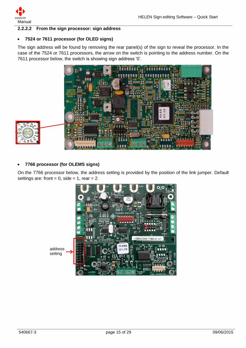
7524 or 7611 processor (for OLED signs)
The sign address will be found by removing the rear panel(s) of the sign to reveal the processor. In the
case of the 7524 or 7611 processors, the arrow on the switch is pointing to the address number. On the
7611 processor below, the switch is showing sign address ‘0’.
7766 processor (for OLEMS signs)
On the 7766 processor below, the address setting is provided by the position of the link jumper. Default
settings are: front = 0, side = 1, rear = 2.
address setting
HELEN Sign-editing Software – Quick Start Manual
540667-3 page 16 of 29 09/06/2015
Destination List Database
Creating a new list
Step Description Figure
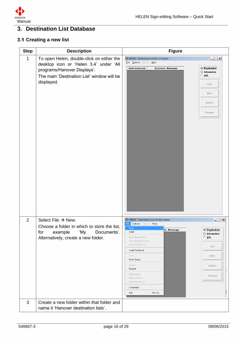
1 To open Helen, double-click on either the
desktop icon or ‘Helen 3.4’ under ‘All
programs/Hanover Displays’.
The main ‘Destination List’ window will be
displayed.
2 Select File New.
Choose a folder in which to store the list,
for example ‘My Documents’.
Alternatively, create a new folder.
3 Create a new folder within that folder and
name it ‘Hanover destination lists’.
HELEN Sign-editing Software – Quick Start Manual
540667-3 page 17 of 29 09/06/2015
Sign Parameter Editor
This is where the sign type, size and address details are entered. An example is shown below, detailing
a bus with 3 signs fitted with standard default switch settings.
Switch setting Position Type Size (W x H)
0 front LED Destination display 144 x 19
1 side LED Destination display 96 x 8
2 rear LED Destination display 32 x 17
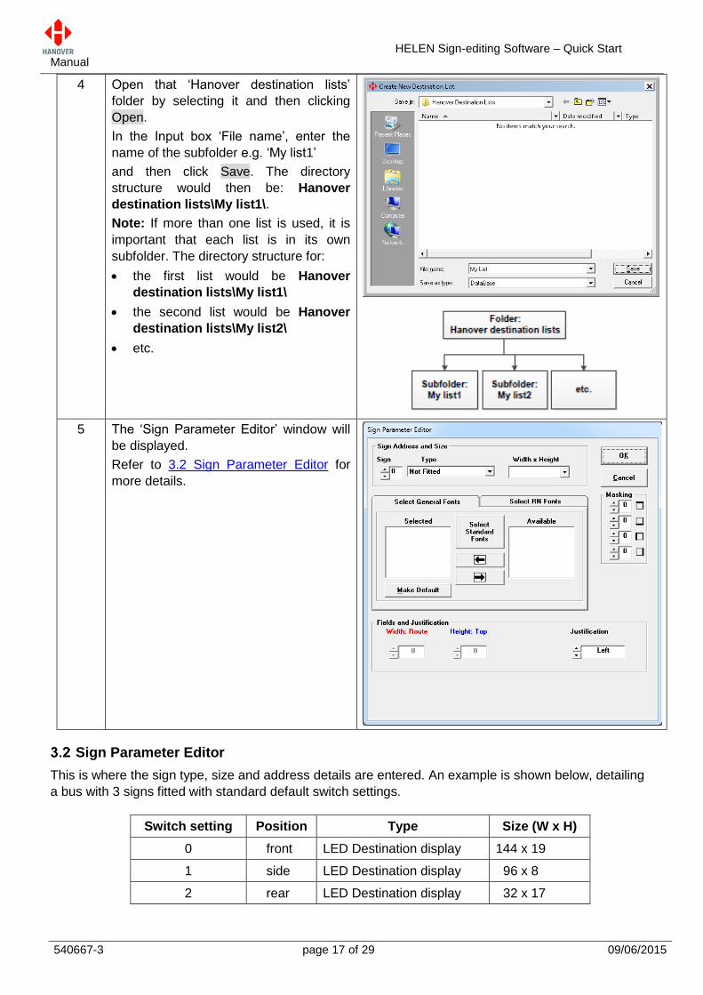
4 Open that ‘Hanover destination lists’
folder by selecting it and then clicking
Open.
In the Input box ‘File name’, enter the
name of the subfolder e.g. ‘My list1’
and then click Save. The directory
structure would then be: Hanover
destination lists\My list1\.
Note: If more than one list is used, it is
important that each list is in its own
subfolder. The directory structure for:
the first list would be Hanover
destination lists\My list1\
the second list would be Hanover
destination lists\My list2\
etc.
5 The ‘Sign Parameter Editor’ window will
be displayed.
Refer to 3.2 Sign Parameter Editor for
more details.
HELEN Sign-editing Software – Quick Start Manual
540667-3 page 18 of 29 09/06/2015
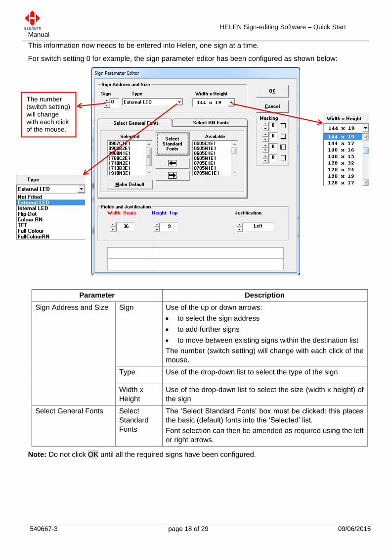
This information now needs to be entered into Helen, one sign at a time.
For switch setting 0 for example, the sign parameter editor has been configured as shown below:
Parameter Description
Sign Address and Size Sign Use of the up or down arrows:
to select the sign address
to add further signs
to move between existing signs within the destination list
The number (switch setting) will change with each click of the
mouse.
Type Use of the drop-down list to select the type of the sign
Width x
Height
Use of the drop-down list to select the size (width x height) of
the sign
Select General Fonts Select
Standard
Fonts
The ‘Select Standard Fonts’ box must be clicked: this places
the basic (default) fonts into the ‘Selected’ list.
Font selection can then be amended as required using the left
or right arrows.
Note: Do not click OK until all the required signs have been configured.
The number (switch setting) will change with each click of the mouse.
HELEN Sign-editing Software – Quick Start Manual
540667-3 page 19 of 29 09/06/2015
Destination Codes and Route Codes
Creating new destinations
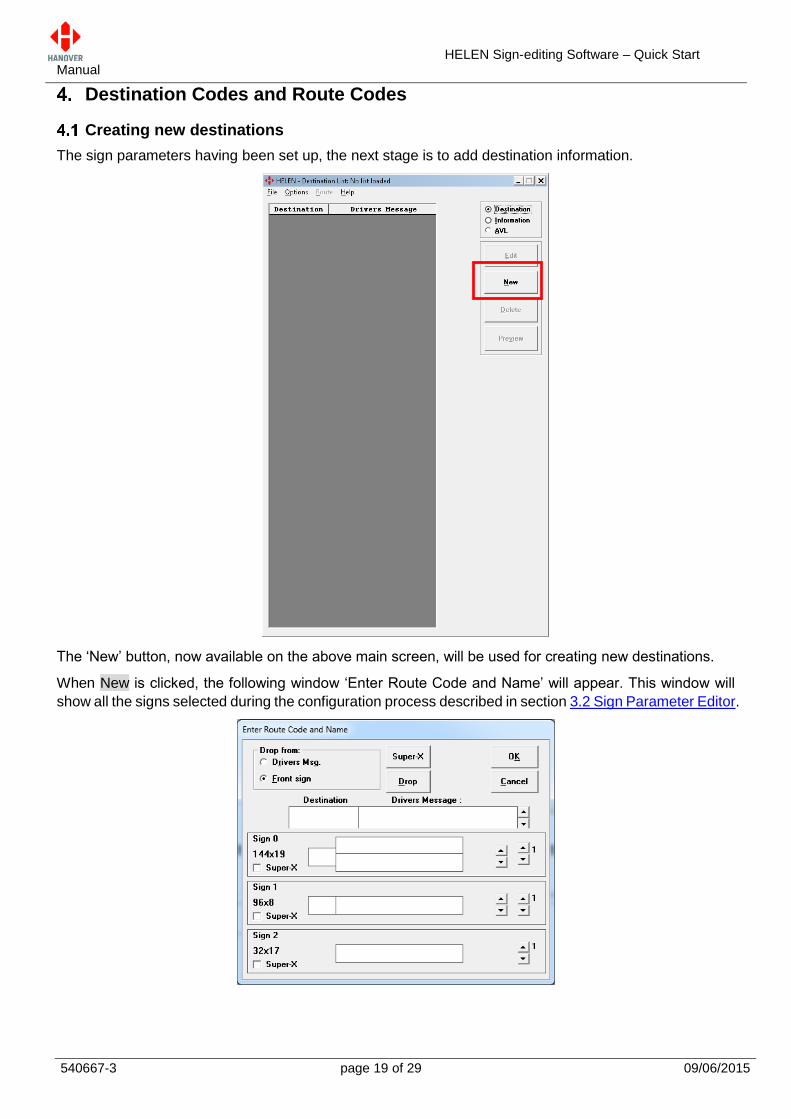
The sign parameters having been set up, the next stage is to add destination information.
The ‘New’ button, now available on the above main screen, will be used for creating new destinations.
When New is clicked, the following window ‘Enter Route Code and Name’ will appear. This window will
show all the signs selected during the configuration process described in section 3.2 Sign Parameter Editor.
HELEN Sign-editing Software – Quick Start Manual
540667-3 page 20 of 29 09/06/2015
Inputting the destination code
In the box marked ‘Destination’, enter the destination code e.g. the first destination on the list – say, 1.
Each code entered must be unique within the list as this is the code to be entered on the controller by the
driver. It can contain up to four alphanumeric characters if required. The ‘Destination’ box will automatically
include additional zeros when the user clicks into another text box. In the figure in section, this has caused
the ‘1’ to become ‘0000000001’.
Entering the sign information
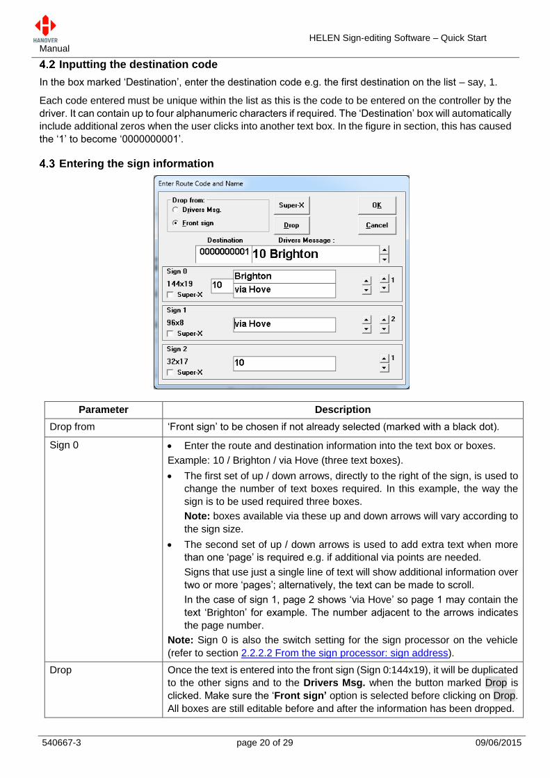
Parameter Description
Drop from ‘Front sign’ to be chosen if not already selected (marked with a black dot).
Sign 0 Enter the route and destination information into the text box or boxes.
Example: 10 / Brighton / via Hove (three text boxes).
The first set of up / down arrows, directly to the right of the sign, is used to
change the number of text boxes required. In this example, the way the
sign is to be used required three boxes.
Note: boxes available via these up and down arrows will vary according to
the sign size.
The second set of up / down arrows is used to add extra text when more
than one ‘page’ is required e.g. if additional via points are needed.
Signs that use just a single line of text will show additional information over
two or more ‘pages’; alternatively, the text can be made to scroll.
In the case of sign 1, page 2 shows ‘via Hove’ so page 1 may contain the
text ‘Brighton’ for example. The number adjacent to the arrows indicates
the page number.
Note: Sign 0 is also the switch setting for the sign processor on the vehicle
(refer to section 2.2.2.2 From the sign processor: sign address).
Drop Once the text is entered into the front sign (Sign 0:144x19), it will be duplicated
to the other signs and to the Drivers Msg. when the button marked Drop is
clicked. Make sure the ‘Front sign’ option is selected before clicking on Drop.
All boxes are still editable before and after the information has been dropped.
HELEN Sign-editing Software – Quick Start Manual
540667-3 page 21 of 29 09/06/2015
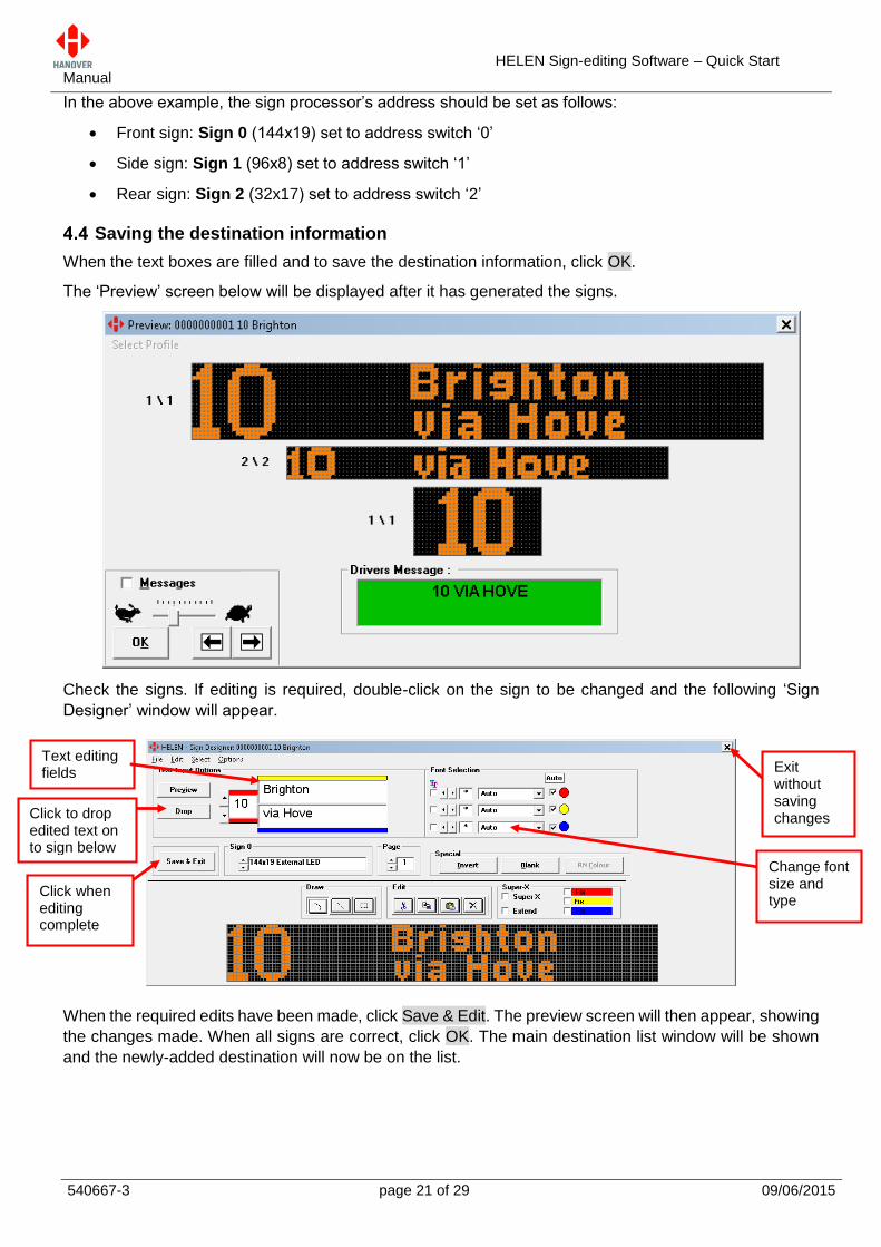
In the above example, the sign processor’s address should be set as follows:
Front sign: Sign 0 (144x19) set to address switch ‘0’
Side sign: Sign 1 (96x8) set to address switch ‘1’
Rear sign: Sign 2 (32x17) set to address switch ‘2’
Saving the destination information
When the text boxes are filled and to save the destination information, click OK.
The ‘Preview’ screen below will be displayed after it has generated the signs.
Check the signs. If editing is required, double-click on the sign to be changed and the following ‘Sign
Designer’ window will appear.
When the required edits have been made, click Save & Edit. The preview screen will then appear, showing
the changes made. When all signs are correct, click OK. The main destination list window will be shown
and the newly-added destination will now be on the list.
Text editing fields
Click to drop edited text on to sign below
Click when editing complete
Exit without saving changes
Change font size and type
HELEN Sign-editing Software – Quick Start Manual
540667-3 page 22 of 29 09/06/2015
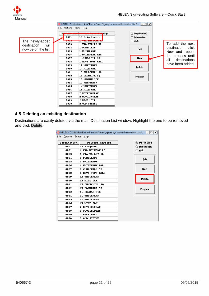
Deleting an existing destination
Destinations are easily deleted via the main Destination List window. Highlight the one to be removed
and click Delete.
To add the next destination, click New and repeat the process until all destinations have been added.
The newly-added destination will now be on the list.
HELEN Sign-editing Software – Quick Start Manual
540667-3 page 23 of 29 09/06/2015
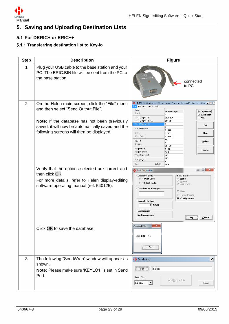
Saving and Uploading Destination Lists
For DERIC+ or ERIC++
Transferring destination list to Key-lo
Step Description Figure
1 Plug your USB cable to the base station and your
PC. The ERIC.BIN file will be sent from the PC to
the base station.
2 On the Helen main screen, click the “File” menu
and then select “Send Output File”.
Note: If the database has not been previously
saved, it will now be automatically saved and the
following screens will then be displayed.
Verify that the options selected are correct and
then click OK.
For more details, refer to Helen display-editing
software operating manual (ref. 540125).
Click OK to save the database.
3 The following “SendWrap” window will appear as
shown.
Note: Please make sure ‘KEYLO1’ is set in Send
Port.
connected to PC
HELEN Sign-editing Software – Quick Start Manual
540667-3 page 24 of 29 09/06/2015
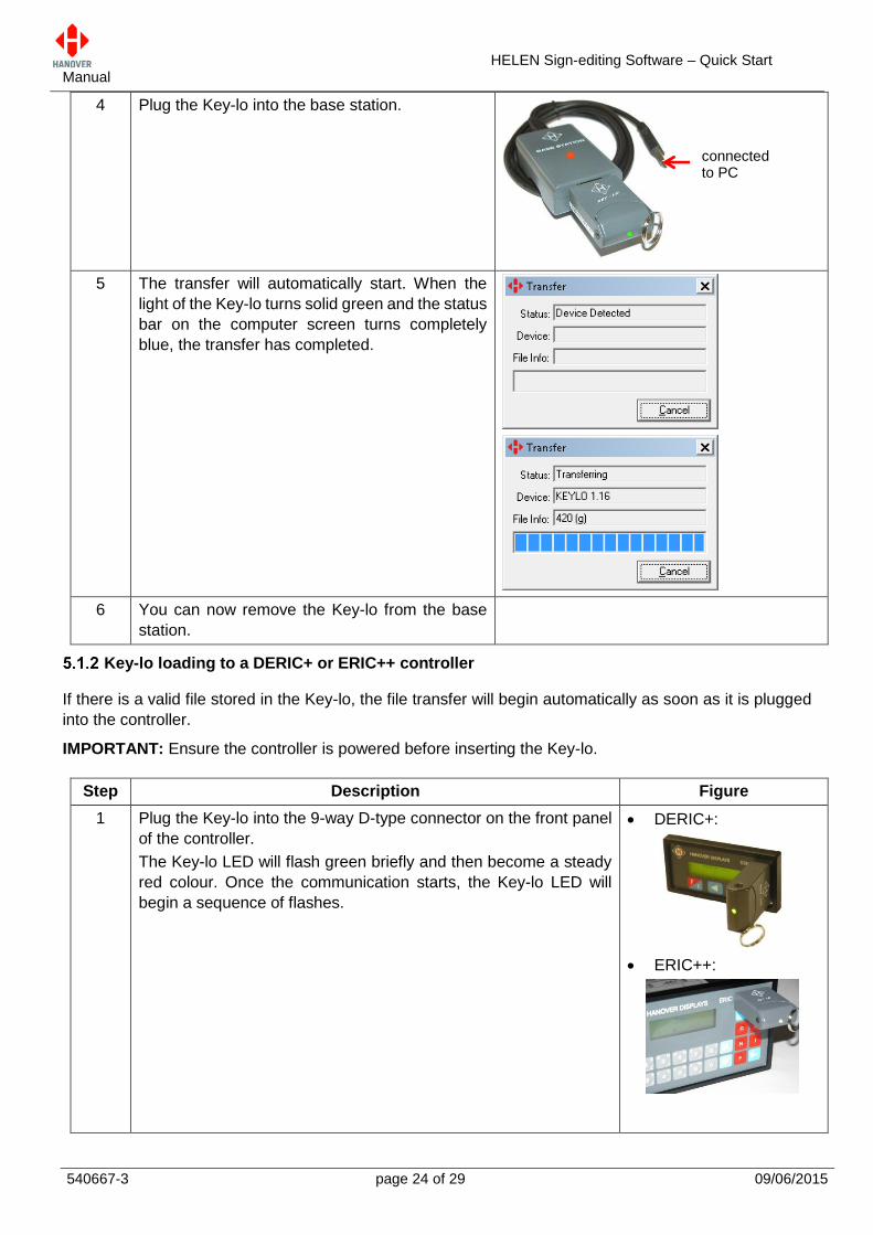
Key-lo loading to a DERIC+ or ERIC++ controller
If there is a valid file stored in the Key-lo, the file transfer will begin automatically as soon as it is plugged
into the controller.
IMPORTANT: Ensure the controller is powered before inserting the Key-lo.
4 Plug the Key-lo into the base station.
5 The transfer will automatically start. When the
light of the Key-lo turns solid green and the status
bar on the computer screen turns completely
blue, the transfer has completed.
6 You can now remove the Key-lo from the base
station.
Step Description Figure
1 Plug the Key-lo into the 9-way D-type connector on the front panel
of the controller.
The Key-lo LED will flash green briefly and then become a steady
red colour. Once the communication starts, the Key-lo LED will
begin a sequence of flashes.
DERIC+:
ERIC++:
connected to PC
HELEN Sign-editing Software – Quick Start Manual
540667-3 page 25 of 29 09/06/2015
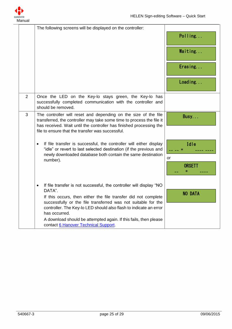
The following screens will be displayed on the controller:
2 Once the LED on the Key-lo stays green, the Key-lo has
successfully completed communication with the controller and
should be removed.
3 The controller will reset and depending on the size of the file
transferred, the controller may take some time to process the file it
has received. Wait until the controller has finished processing the
file to ensure that the transfer was successful.
If file transfer is successful, the controller will either display
“idle” or revert to last selected destination (if the previous and
newly downloaded database both contain the same destination
number).
If file transfer is not successful, the controller will display “NO
DATA”.
If this occurs, then either the file transfer did not complete
successfully or the file transferred was not suitable for the
controller. The Key-lo LED should also flash to indicate an error
has occurred.
A download should be attempted again. If this fails, then please
contact 6 Hanover Technical Support.
or
Loading...
Erasing...
Waiting...
Polling...
NO DATA
ORSETT
-- * ---- 0032
Idle
-- -- * ---- ----
Busy...
HELEN Sign-editing Software – Quick Start Manual
540667-3 page 26 of 29 09/06/2015
For DG3 or EG3
Configuring the USB stick for loading
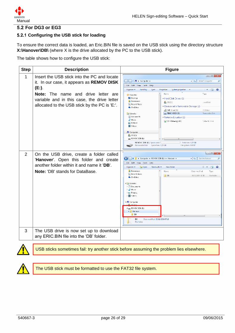
To ensure the correct data is loaded, an Eric.BIN file is saved on the USB stick using the directory structure
X:\Hanover\DB\ (where X is the drive allocated by the PC to the USB stick).
The table shows how to configure the USB stick:
Step Description Figure
1 Insert the USB stick into the PC and locate
it. In our case, it appears as REMOV DISK
(E:).
Note: The name and drive letter are
variable and in this case, the drive letter
allocated to the USB stick by the PC is 'E:'.
2 On the USB drive, create a folder called
'Hanover'. Open this folder and create
another folder within it and name it 'DB'.
Note: 'DB' stands for DataBase.
3 The USB drive is now set up to download
any ERIC.BIN file into the ‘DB’ folder.
USB sticks sometimes fail: try another stick before assuming the problem lies elsewhere.
The USB stick must be formatted to use the FAT32 file system.
HELEN Sign-editing Software – Quick Start Manual
540667-3 page 27 of 29 09/06/2015
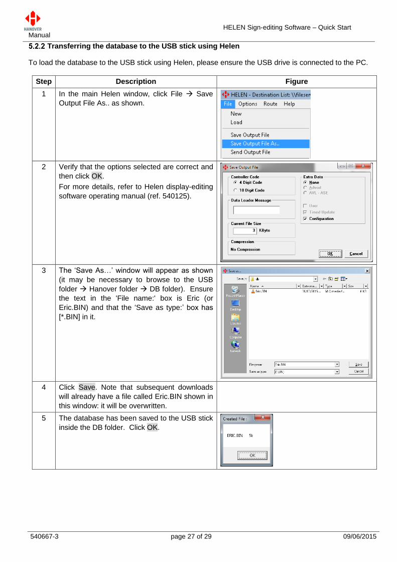
Transferring the database to the USB stick using Helen
To load the database to the USB stick using Helen, please ensure the USB drive is connected to the PC.
Step Description Figure
1 In the main Helen window, click File Save
Output File As.. as shown.
2 Verify that the options selected are correct and
then click OK.
For more details, refer to Helen display-editing
software operating manual (ref. 540125).
3 The ‘Save As…’ window will appear as shown
(it may be necessary to browse to the USB
folder Hanover folder DB folder). Ensure
the text in the 'File name:' box is Eric (or
Eric.BIN) and that the ‘Save as type:’ box has
[*.BIN] in it.
4 Click Save. Note that subsequent downloads
will already have a file called Eric.BIN shown in
this window: it will be overwritten.
5 The database has been saved to the USB stick
inside the DB folder. Click OK.
HELEN Sign-editing Software – Quick Start Manual
540667-3 page 28 of 29 09/06/2015
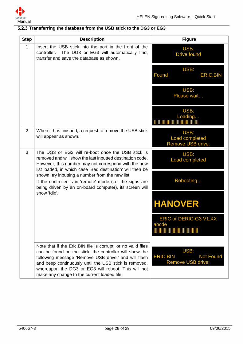
Transferring the database from the USB stick to the DG3 or EG3
Step Description Figure
1 Insert the USB stick into the port in the front of the
controller. The DG3 or EG3 will automatically find,
transfer and save the database as shown.
2 When it has finished, a request to remove the USB stick
will appear as shown.
3 The DG3 or EG3 will re-boot once the USB stick is
removed and will show the last inputted destination code.
However, this number may not correspond with the new
list loaded, in which case 'Bad destination' will then be
shown: try inputting a number from the new list.
If the controller is in 'remote' mode (i.e. the signs are
being driven by an on-board computer), its screen will
show 'Idle'.
Note that if the Eric.BIN file is corrupt, or no valid files
can be found on the stick, the controller will show the
following message 'Remove USB drive:' and will flash
and beep continuously until the USB stick is removed,
whereupon the DG3 or EG3 will reboot. This will not
make any change to the current loaded file.
USB: Loading…
||||||||||||||||||||||||||||||||||| |||||||||
USB: Please wait…
|||||||||
USB: Found ERIC.BIN |||||||||
USB: Drive found
|||||||||
USB: Load completed
Remove USB drive: |||||||||
ERIC or DERIC-G3 V1.XX abcde |||||||||||||||||||||||||||||||||||
HANOVER
Rebooting…
|||||||||
USB: Load completed
|||||||||
USB: ERIC.BIN Not Found
Remove USB drive:
HELEN Sign-editing Software – Quick Start Manual
540667-3 page 29 of 29 09/06/2015
Hanover Technical Support
United Kingdom
Please do not hesitate to contact Hanover Technical Support located in Lewes, UK for any problem
encountered or for any advice needed for using the Helen software:
Contact
Phone +44 (0)1273 477528 Ext.615 or Option 2
Email [email protected]
United States of America
Please do not hesitate to contact Hanover Technical Support located in USA for any problem encountered
or for any advice needed for using the Helen software:
Contact
Phone +1 (773) 334 9934
Email [email protected]