Embed Size (px)
Citation preview
Installation Instructions
Heidenhain Feedback Option Card for PowerFlex 700S Phase II Drives
ATTENTION: This Feedback Option Card is only for use with PowerFlex 700S Phase II Control.
What This Kit Contains Verify that your kit contains the items listed in the following table. If your kit does not contain the correct items, contact your Rockwell Automation sales representative.
Tools That You Need • Phillips® screwdriver for M3 screws• Pozidrive® screwdriver for M4 screws (for high power drives only)• Nut driver or wrench for M3 hex nut• Nut driver or wrench for M5 hex nutPhillips® is a registered trademark of Phillips Screw CompanyPozidrive® is a registered trademark of Phillips Screw Company
!ATTENTION: To avoid an electric shock hazard, verify that the voltage on the bus capacitors has discharged before performing any work on the drive. Measure the DC bus voltage at the +DC & –DC terminals of the Power Terminal Block. The voltage must be zero.
!ATTENTION: HOT surfaces can cause severe burns. Do not touch the heatsink surface during operation of the drive. After disconnecting power allow time for cooling.
!ATTENTION: This drive contains ESD (Electrostatic Discharge) sensitive parts and assemblies. Static control precautions are required when installing, testing, servicing or repairing this assembly. Component damage may result if ESD control procedures are not followed. If you are not familiar with static control procedures, reference A-B publication 8000-4.5.2, “Guarding Against Electrostatic Damage” or any other applicable ESD protection handbook.
Quantity: Description
1 Heidenhain Feedback Option circuit board
2 34 - pin “stacker” connectors
3 Screws with captive lock washers
2 Heidenhain Feedback Option Card for PowerFlex 700S Phase II Drives
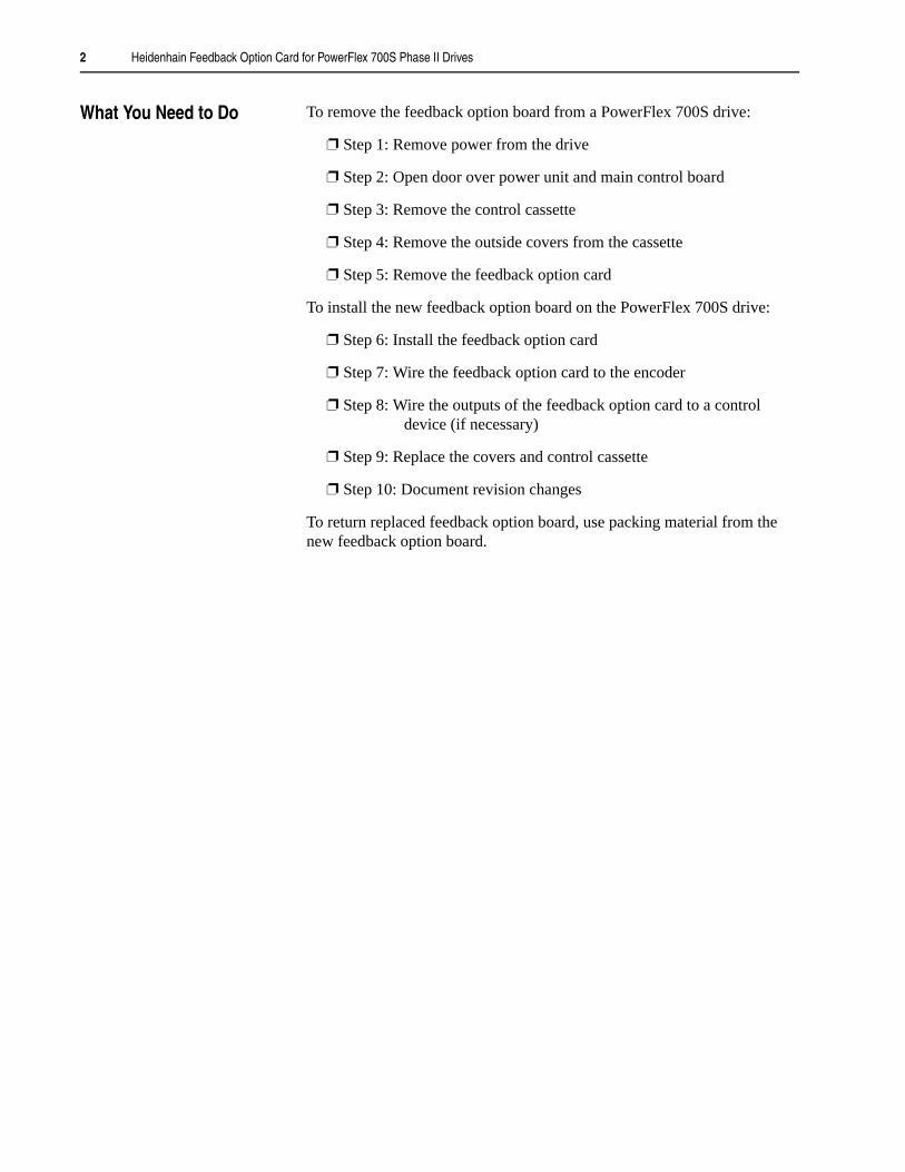
What You Need to Do To remove the feedback option board from a PowerFlex 700S drive:
❐ Step 1: Remove power from the drive
❐ Step 2: Open door over power unit and main control board
❐ Step 3: Remove the control cassette
❐ Step 4: Remove the outside covers from the cassette
❐ Step 5: Remove the feedback option card
To install the new feedback option board on the PowerFlex 700S drive:
❐ Step 6: Install the feedback option card
❐ Step 7: Wire the feedback option card to the encoder
❐ Step 8: Wire the outputs of the feedback option card to a control device (if necessary)
❐ Step 9: Replace the covers and control cassette
❐ Step 10: Document revision changes
To return replaced feedback option board, use packing material from the new feedback option board.
Heidenhain Feedback Option Card for PowerFlex 700S Phase II Drives 3
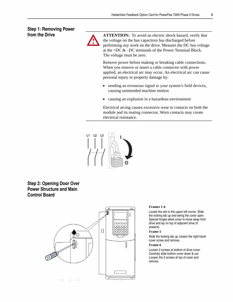
Step 1: Removing Power from the Drive
Step 2: Opening Door Over Power Structure and Main Control Board
!ATTENTION: To avoid an electric shock hazard, verify that the voltage on the bus capacitors has discharged before performing any work on the drive. Measure the DC bus voltage at the +DC & –DC terminals of the Power Terminal Block. The voltage must be zero.
Remove power before making or breaking cable connections. When you remove or insert a cable connector with power applied, an electrical arc may occur. An electrical arc can cause personal injury or property damage by:
• sending an erroneous signal to your system’s field devices, causing unintended machine motion
• causing an explosion in a hazardous environment
Electrical arcing causes excessive wear to contacts on both the module and its mating connector. Worn contacts may create electrical resistance.
L1 L2 L3
O
I
Frames 1-4Locate the slot in the upper left corner. Slide the locking tab up and swing the cover open.Special hinges allow cover to move away from drive and lay on top of adjacent drive (if present).Frame 5Slide the locking tab up, loosen the right-hand cover screw and remove.Frame 6Loosen 2 screws at bottom of drive cover.Carefully slide bottom cover down & out. Loosen the 2 screws at top of cover and remove.

4 Heidenhain Feedback Option Card for PowerFlex 700S Phase II Drives
Step 3: Removing the Control Cassette
It is necessary to remove the control cassette from the drive for installing the Heidenhain Feedback Option Card.
BR1BR2DC+DC-PEU/T1V/T2W/T3R/L1 L2
C
B
A
=
Removing the Cassette
Task Description
Disconnect the cables that connect the main board
Loosen 2 screws on face of cassette
Remove the cassette
A
B
C
Step 4: Removing the Outside Covers from the Cassette
Task Description
Loosen 2 screws on face of front cover and remove the cover
Loosen 3 screws on side of rear cover and remove the cover
A
B
A
B
Proper tightening torque for reassembly is 1 Nm (7 to 10 lb-in)
=
B
Heidenhain Feedback Option Card for PowerFlex 700S Phase II Drives 5
Step 5: Removing the Feedback Option Card
If you are replacing the the Feedback Option card with a new one, the procedure is the reverse of installing the Heidenhain Feedback Option card, as shown in the next step 6.
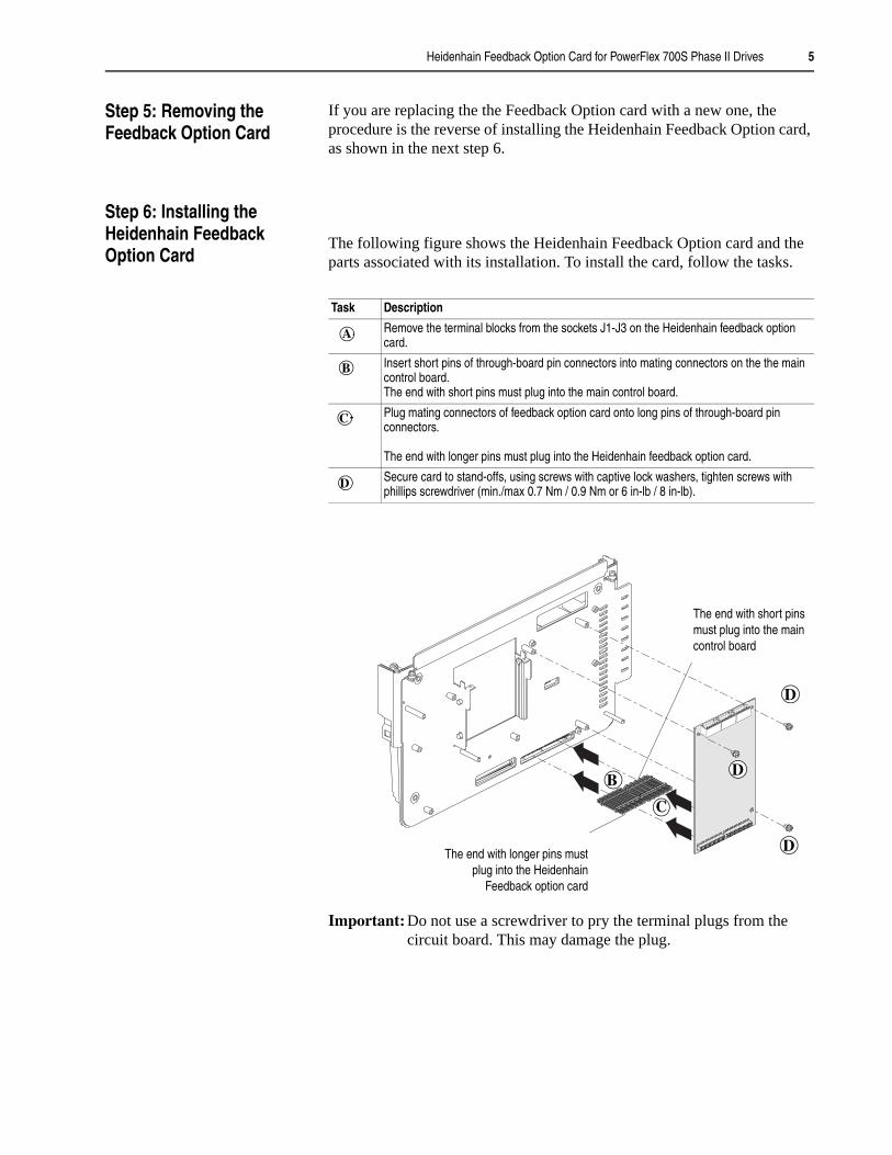
Step 6: Installing the Heidenhain Feedback Option Card
The following figure shows the Heidenhain Feedback Option card and the parts associated with its installation. To install the card, follow the tasks.
Important: Do not use a screwdriver to pry the terminal plugs from the circuit board. This may damage the plug.
Task Description
Remove the terminal blocks from the sockets J1-J3 on the Heidenhain feedback option card.
Insert short pins of through-board pin connectors into mating connectors on the the main control board.The end with short pins must plug into the main control board.
Plug mating connectors of feedback option card onto long pins of through-board pin connectors.
The end with longer pins must plug into the Heidenhain feedback option card.
Secure card to stand-offs, using screws with captive lock washers, tighten screws with phillips screwdriver (min./max 0.7 Nm / 0.9 Nm or 6 in-lb / 8 in-lb).
A
B
C
D
The end with longer pins mustplug into the Heidenhain
Feedback option card
The end with short pins must plug into the main control board
D
C
BD
D

6 Heidenhain Feedback Option Card for PowerFlex 700S Phase II Drives
Step 7: Wiring the Heidenhain Feedback Option Card to an Encoder
Terminal blocks J1, J2 contain connection points for a Heidenhain encoder with EnDat interface and terminal block J3 contains connection points for a simulated incremental encoder output. These terminal blocks reside on the Encoder Feedback Option card.
NOTE: The terminal blocks are keyed, but without designation label.
Task Description
Connect the encoder and control device cable (if used) to the terminal block plugs J1-J3.
Re-install the plugs, when wiring is complete.
Route and secure cables. Use cable ties to anchor cables to slots on this flange for strain relief.
A
B
C
J1
J2
J3
J3
J2
J1
A
B
C
Encoder Connections Terminal Signal Description
J2-7 0V SENSOR Sensor lines of the voltage at the encoderJ2-6 Up SENSOR
J2-5 POWER COMMON Power supply for the encoder interface.J2-4 POWER Up
J2-3 B- Neg. sinusoidal incremental signal
J2-2 B+ Pos. sinusoidal incremental signal
J2-1 A- Neg. cosinusoidal incremental signal
J1-7 A+ Pos. cosinusoidal incremental signal
J1-6 INTERNAL SHIELD Analog signals shield
J1-5 SHIELD Cable shield
J1-4 CLOCK- Synchronization clock signal
J1-3 CLOCK+
J1-2 DATA- (RS 485) Data input /output signal lines of serial data transmissionJ1-1 DATA+ (RS 485)
J1
J2
7654321
7654321
Heidenhain Feedback Option Card for PowerFlex 700S Phase II Drives 7
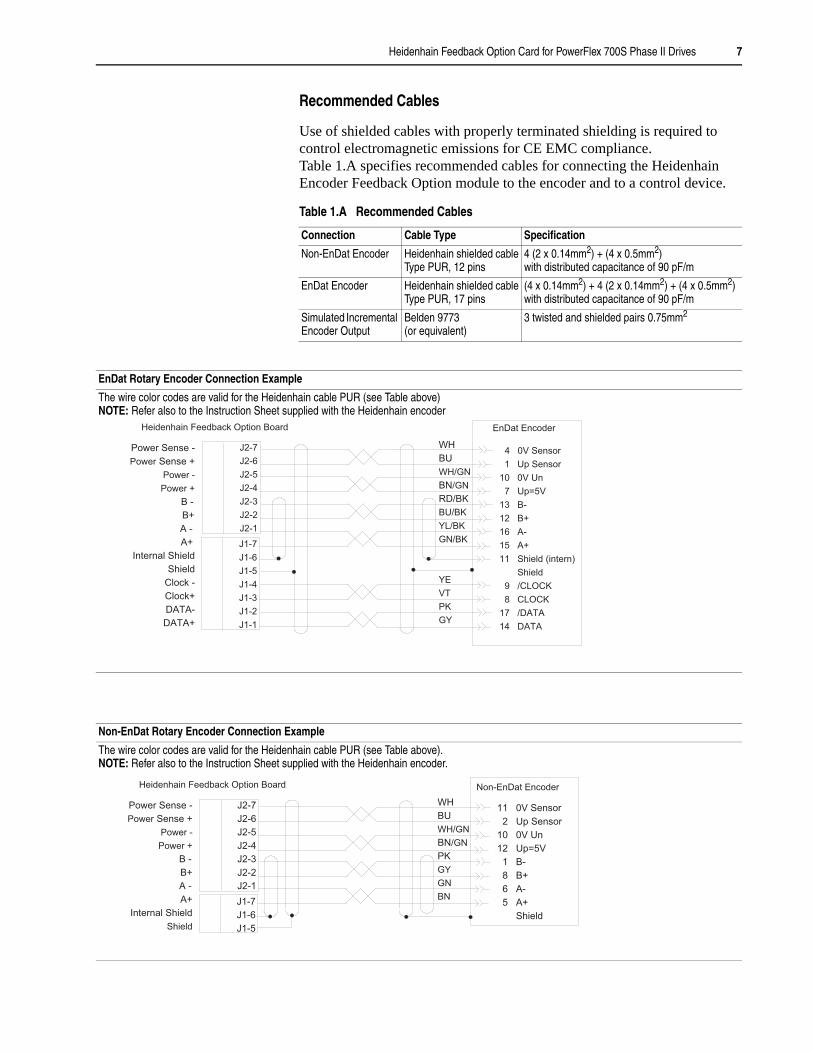
Recommended Cables
Use of shielded cables with properly terminated shielding is required to control electromagnetic emissions for CE EMC compliance.Table 1.A specifies recommended cables for connecting the Heidenhain Encoder Feedback Option module to the encoder and to a control device.
Table 1.A Recommended Cables
Connection Cable Type Specification
Non-EnDat Encoder Heidenhain shielded cableType PUR, 12 pins
4 (2 x 0.14mm2) + (4 x 0.5mm2)with distributed capacitance of 90 pF/m
EnDat Encoder Heidenhain shielded cableType PUR, 17 pins
(4 x 0.14mm2) + 4 (2 x 0.14mm2) + (4 x 0.5mm2)with distributed capacitance of 90 pF/m
Simulated Incremental Encoder Output
Belden 9773 (or equivalent)
3 twisted and shielded pairs 0.75mm2
EnDat Rotary Encoder Connection Example
The wire color codes are valid for the Heidenhain cable PUR (see Table above)NOTE: Refer also to the Instruction Sheet supplied with the Heidenhain encoder
4 0V Sensor
1 Up Sensor
10 0V Un
7 Up=5V
13 B-
12 B+
16 A-
15 A+
11 Shield (intern)
Shield
9 /CLOCK
8 CLOCK
17 /DATA
14 DATA
J2-7
J2-6
J2-5
J2-4
J2-3
J2-2
J2-1
WH
BU
WH/GN
BN/GN
RD/BK
BU/BK
YL/BK
GN/BK
YE
VT
PK
GY
J1-7
J1-6
J1-5
J1-4
J1-3
J1-2
J1-1
Power Sense -
Power Sense +
Power -
Power +
B -
B+
A -
A+
Internal Shield
Shield
Clock -
Clock+
DATA-
DATA+
EnDat EncoderHeidenhain Feedback Option Board
Non-EnDat Rotary Encoder Connection Example
The wire color codes are valid for the Heidenhain cable PUR (see Table above). NOTE: Refer also to the Instruction Sheet supplied with the Heidenhain encoder.
11 0V Sensor
2 Up Sensor
10 0V Un
12 Up=5V
1 B-
8 B+
6 A-
5 A+
Shield
J2-7
J2-6
J2-5
J2-4
J2-3
J2-2
J2-1
WH
BU
WH/GN
BN/GN
PK
GY
GN
BNJ1-7
J1-6
J1-5
Power Sense -
Power Sense +
Power -
Power +
B -
B+
A -
A+
Internal Shield
Shield
Non-EnDat EncoderHeidenhain Feedback Option Board
8 Heidenhain Feedback Option Card for PowerFlex 700S Phase II Drives
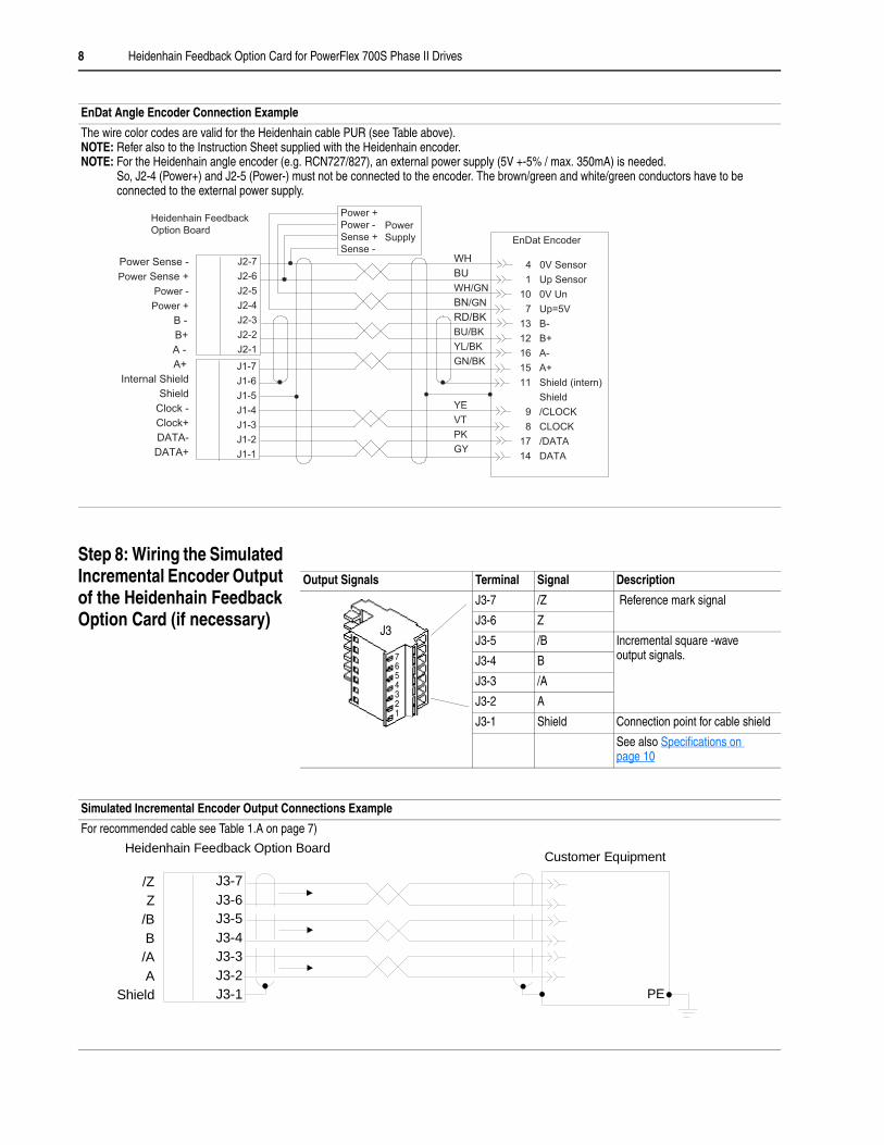
Step 8: Wiring the Simulated Incremental Encoder Output of the Heidenhain Feedback Option Card (if necessary)
EnDat Angle Encoder Connection Example
The wire color codes are valid for the Heidenhain cable PUR (see Table above). NOTE: Refer also to the Instruction Sheet supplied with the Heidenhain encoder.NOTE: For the Heidenhain angle encoder (e.g. RCN727/827), an external power supply (5V +-5% / max. 350mA) is needed.
So, J2-4 (Power+) and J2-5 (Power-) must not be connected to the encoder. The brown/green and white/green conductors have to be connected to the external power supply.
4 0V Sensor
1 Up Sensor
10 0V Un
7 Up=5V
Power +
Power -
Sense +
Sense -
13 B-
12 B+
16 A-
15 A+
11 Shield (intern)
Shield
9 /CLOCK
8 CLOCK
17 /DATA
14 DATA
J2-7
J2-6
J2-5
J2-4
J2-3
J2-2
J2-1
WH
BU
WH/GN
BN/GN
RD/BK
BU/BK
YL/BK
GN/BK
YE
VT
PK
GY
J1-7
J1-6
J1-5
J1-4
J1-3
J1-2
J1-1
Power Sense -
Power Sense +
Power -
Power +
B -
B+
A -
A+
Internal Shield
Shield
Clock -
Clock+
DATA-
DATA+
EnDat Encoder
Heidenhain Feedback
Option BoardPower
Supply
Output Signals Terminal Signal Description
J3-7 /Z Reference mark signal
J3-6 Z
J3-5 /B Incremental square -wave output signals.J3-4 B
J3-3 /A
J3-2 A
J3-1 Shield Connection point for cable shield
See also Specifications on page 10
J3
7654321
Simulated Incremental Encoder Output Connections Example
For recommended cable see Table 1.A on page 7)
J3-7J3-6J3-5J3-4J3-3J3-2J3-1
/ZZ
/BB/AA
Shield
Customer EquipmentHeidenhain Feedback Option Board
PE

Heidenhain Feedback Option Card for PowerFlex 700S Phase II Drives 9
Step 9: Replacing the Covers and Control Cassette
Important: The procedure for replacing the covers and control cassette is the reverse of removing these components. Refer to Step 3: Removing the Control Cassette on page 4. and Step 4: Removing the Outside Covers from the Cassette on page 4
Step 10: Documenting Revision Changes
Document drive revisions on the “Field Installed Options” tag. Use the blank line if you are installing the Heidenhain Feedback option in a drive that was manufactured without it.
FIELD INSTALLED OPTIONS
Firmware #: Date
Firmware
20-HIM
28-IO-
20-COMM-
20B_-DB1-
HIM
I/O
COM Module
Internal Dynamic Brake
#: Date

10 Heidenhain Feedback Option Card for PowerFlex 700S Phase II Drives
Specifications Heidenhain Feedback Option Card Specifications
Table 1.B General Data
Table 1.C Simulated Incremental Encoder Output Data
Consideration Description
Encoder Power Supply 5V dc ±5% @ 250 mA
Position Format- Bits per Revolution- Distinguishable Revolutions
20 bits for multi-turn and 20 or 24 bits for single-turn4096 (12 bits) (Multiturn)
Incremental Signals- Line Count- Cut-off Frequency
Sine/Cosine 1V P-P Offset 2.5512, 1024, 2048, 4096, 32768 < 180 kHz
Maximum Cable Length 150m (492 ft.)
Maximum Frequency(Encoder Speed)
(300 RPM for encoders with 32768 sine cycles per revolution)(1800 RPM for encoders with 4096 sine cycles per revolution)(3600 RPM for encoders with 2048 sine cycles per revolution)(7200 RPM for encoders with 1024 sine cycles per revolution)(10000 RPM for encoders with 512 sine cycles per revolution)
Consideration Description
Simulated Output
- Maximum Frequency
5V TTL / 25 mAMaximum short circuit protection current: 50 mA200 kHzSignals Pattern
/Z
Z
/B
B
/A
A
5V
5V
5V
5V
5V
5V
T= = = =

Heidenhain Feedback Option Card for PowerFlex 700S Phase II Drives 11
Supported EnDat Devices
Table 1.D specifies which EnDat rotary encoders are supported by the PowerFlex 700S Phase II Heidenhain Encoder Feedback Option module.
Table 1.D Supported Heidenhain EnDat Devices - Rotary Encoders
Table 1.E specifies which EnDat angle encoders are supported. For these angle encoders, firmware with version 3.01 or higher is required for PowerFlex 700S and firmware version 2.0 or higher with ID 16720 (indicated by Par.249 on version 2.0) is required for Heidenhein option. An external power supply (5V +-5% / max. 350mA without load) is required for the encoder. See EnDat Angle Encoder Connection Example.
Table 1.E Supported Heidenhain EnDat Devices - Angle Encoders
RCN729/829 is the upgrade of the angle encoder RCN727/827 with EnDat 2.2 or EnDat 2.1 communication interface. Therefore indication of the used interface with EnDat 2.1 is required when ordering.
RCN226 is the upgrade of the angle encoder RCN220.
ModelDistinguishable Revolutions (Multi-turn) Line Counts Mechanical Mounting
ECN 113 - 2048 Rotary encoders with mounted stator coupling, blind hollow shaft or hollow through shaft
ECN 413, ECN 1313 - 512 / 2048
ECN 1113 - 512
EQN 425, EQN 1325 4096 (12 bits) 512 / 2048
EQN 1125 4096 (12 bits) 512
ROC 413 - 512 / 2048 Rotary encoder for separate shaft coupling with synchro flangeROQ 425 4096 (12 bits) 512 / 2048
ROC 415 - 8192
Interface EnDat 2.1 (serial bidirectional)
Output Incremental Signals
Sinusoidal voltage signals ~ 1 VPP2 nearly sinusoidal signals A and B
Signal amplitude M:Asymmetry IP - NI/2M:Signal ratio MA/MB:Phase angle Iϕ1 + ϕ2I/2:
0.8 to 1.2 VPPTypically 1 VPP0.065/0.050.8 to 1.25/0.9 to 1.190° ±10° elec./±5° elec.
ModelDistinguishable Revolutions Line Counts Mechanical Mounting
RCN 727 - 32 768 Angle encoders with mounted stator coupling, hollow through shaftRCN 827 - 32 768
RCN 729 - 32 768
RCN 829 - 32 768
RCN 220 - 16 384
RCN 226 - 16 384
12 Heidenhain Feedback Option Card for PowerFlex 700S Phase II Drives
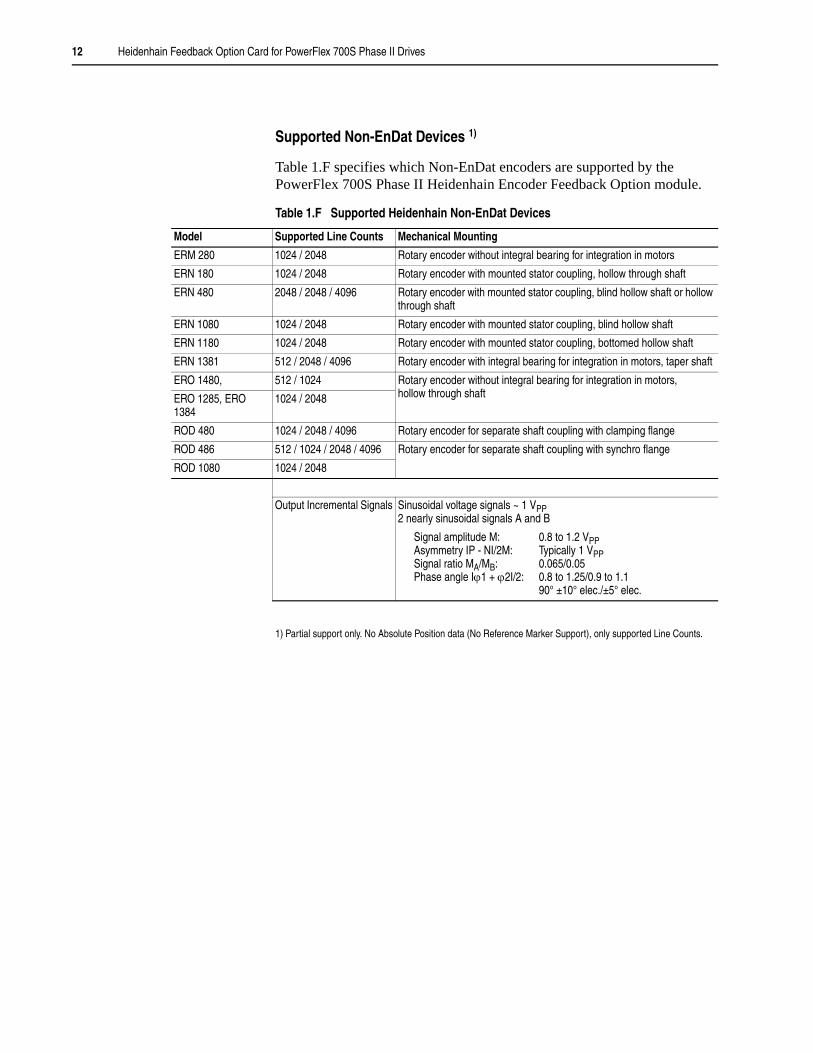
Supported Non-EnDat Devices 1)
Table 1.F specifies which Non-EnDat encoders are supported by the PowerFlex 700S Phase II Heidenhain Encoder Feedback Option module.
Table 1.F Supported Heidenhain Non-EnDat Devices
1) Partial support only. No Absolute Position data (No Reference Marker Support), only supported Line Counts.
Model Supported Line Counts Mechanical Mounting
ERM 280 1024 / 2048 Rotary encoder without integral bearing for integration in motors
ERN 180 1024 / 2048 Rotary encoder with mounted stator coupling, hollow through shaft
ERN 480 2048 / 2048 / 4096 Rotary encoder with mounted stator coupling, blind hollow shaft or hollow through shaft
ERN 1080 1024 / 2048 Rotary encoder with mounted stator coupling, blind hollow shaft
ERN 1180 1024 / 2048 Rotary encoder with mounted stator coupling, bottomed hollow shaft
ERN 1381 512 / 2048 / 4096 Rotary encoder with integral bearing for integration in motors, taper shaft
ERO 1480, 512 / 1024 Rotary encoder without integral bearing for integration in motors, hollow through shaftERO 1285, ERO
13841024 / 2048
ROD 480 1024 / 2048 / 4096 Rotary encoder for separate shaft coupling with clamping flange
ROD 486 512 / 1024 / 2048 / 4096 Rotary encoder for separate shaft coupling with synchro flange
ROD 1080 1024 / 2048
Output Incremental Signals Sinusoidal voltage signals ~ 1 VPP2 nearly sinusoidal signals A and B
Signal amplitude M:Asymmetry IP - NI/2M:Signal ratio MA/MB:Phase angle Iϕ1 + ϕ2I/2:
0.8 to 1.2 VPPTypically 1 VPP0.065/0.050.8 to 1.25/0.9 to 1.190° ±10° elec./±5° elec.
Heidenhain Feedback Option Card for PowerFlex 700S Phase II Drives 13
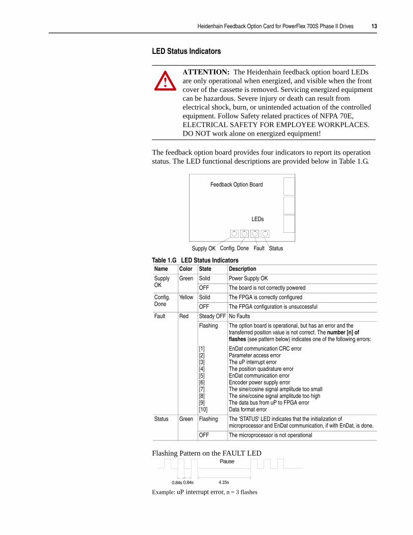
LED Status Indicators
The feedback option board provides four indicators to report its operation status. The LED functional descriptions are provided below in Table 1.G.
Table 1.G LED Status Indicators
Flashing Pattern on the FAULT LED
Example: uP interrupt error, n = 3 flashes
!ATTENTION: The Heidenhain feedback option board LEDs are only operational when energized, and visible when the front cover of the cassette is removed. Servicing energized equipment can be hazardous. Severe injury or death can result from electrical shock, burn, or unintended actuation of the controlled equipment. Follow Safety related practices of NFPA 70E, ELECTRICAL SAFETY FOR EMPLOYEE WORKPLACES. DO NOT work alone on energized equipment!
Name Color State Description
Supply OK
Green Solid Power Supply OK
OFF The board is not correctly powered
Config.Done
Yellow Solid The FPGA is correctly configured
OFF The FPGA configuration is unsuccessful
Fault Red Steady OFF No Faults
Flashing The option board is operational, but has an error and the transferred position value is not correct. The number [n] of flashes (see pattern below) indicates one of the following errors:
[1][2][3][4][5][6][7][8][9][10]
EnDat communication CRC errorParameter access errorThe uP interrupt error The position quadrature errorEnDat communication errorEncoder power supply errorThe sine/cosine signal amplitude too smallThe sine/cosine signal amplitude too highThe data bus from uP to FPGA errorData format error
Status Green Flashing The 'STATUS' LED indicates that the initialization of microprocessor and EnDat communication, if with EnDat, is done.
OFF The microprocessor is not operational
Status
Config. DoneSupply OK
LEDs
Feedback Option Board
Fault
Pause
4.15s0.84s 0.84s

14 Heidenhain Feedback Option Card for PowerFlex 700S Phase II Drives

Heidenhain Feedback Option Card for PowerFlex 700S Phase II Drives 15

Publication 20D-IN017B-EN-P - September 2006Copyright © 2006 Rockwell Automation. All rights reserved. Printed in Switzerland.