Embed Size (px)
Citation preview

HEDM-55xx/560x & HEDS-55xx/56xx Quick Assembly Two and Three Channel Optical Encoders
Data Sheet
ESD WARNING: NORMAL HANDLING PRECAUTIONS SHOULD BE TAKEN TO AVOID STATIC DISCHARGE.
Description
The HEDS-5500/5540, HEDS-5600/5640, HEDM-5500/5540 and HEDM-5600 are high performance, low cost, two and three channel optical incremental encoders. These encoders emphasize high reliability, high resolution, and easy assembly.
Each encoder contains a lensed LED source, an integrated circuit with detectors and output circuitry, and a codewheel which rotates between the emitter and detector IC. The outputs of the HEDS-5500/5600 and HEDM-5500/ 5600 are two square waves in quadrature. The HEDS-5540/5640 and HEDM-5540 also have a third channel index output in addition to the two channel quadrature. This index output is a 90 electrical degree, high true index pulse which is generated once for each full rotation of the codewheel.
The HEDS series utilizes metal codewheels, while the HEDM series utilizes a film codewheel allowing for resolu-tions to 1024 CPR.
These encoders may be quickly and easily mounted to a motor. For larger diameter motors, the HEDM-5600, and HEDS-5600/5640 feature external mounting ears.
The quadrature signals and the index pulse are accessed through five 0.025 inch square pins located on 0.1 inch centers.
Standard resolutions between 96 and 1024 counts per revolution are presently available. Consult local Avago sales representatives for other resolutions.
HEDM-55xx/560x HEDS-550x/554x, HEDS-560x/564x
Features
� Two channel quadrature output with optional index
pulse
� Quick and easy assembly
� No signal adjustment required
� External mounting ears available
� Low cost
� Resolutions up to 1024 counts per revolution
� Small size –40°C to 100°C operating temperature
� TTL compatible
� Single 5 V supply
Applications
The HEDS-5500, 5540, 5600, 5640, and the HEDM-5500, 5540,5600 provide motion detection at a low cost, making them ideal for high volume applications. Typical applica-tions include printers, plotters, tape drives, positioning tables, and automatic handlers.
Note: Avago Technologies encoders are not recommend-ed for use in safety critical applications. Eg. ABS braking systems, power steering, life support systems and critical care medical equipment. Please contact sales representa-tive if more clarification is needed.
2
Package Dimensions
HEDS-5500/5540, HEDM-5500/5540
*Note: For the HEDS-5500 and HEDM-5500, Pin #2 is a No Connect. For the HEDS-5540 and HEDM-5540, Pin #2 is CH. I, the index output.
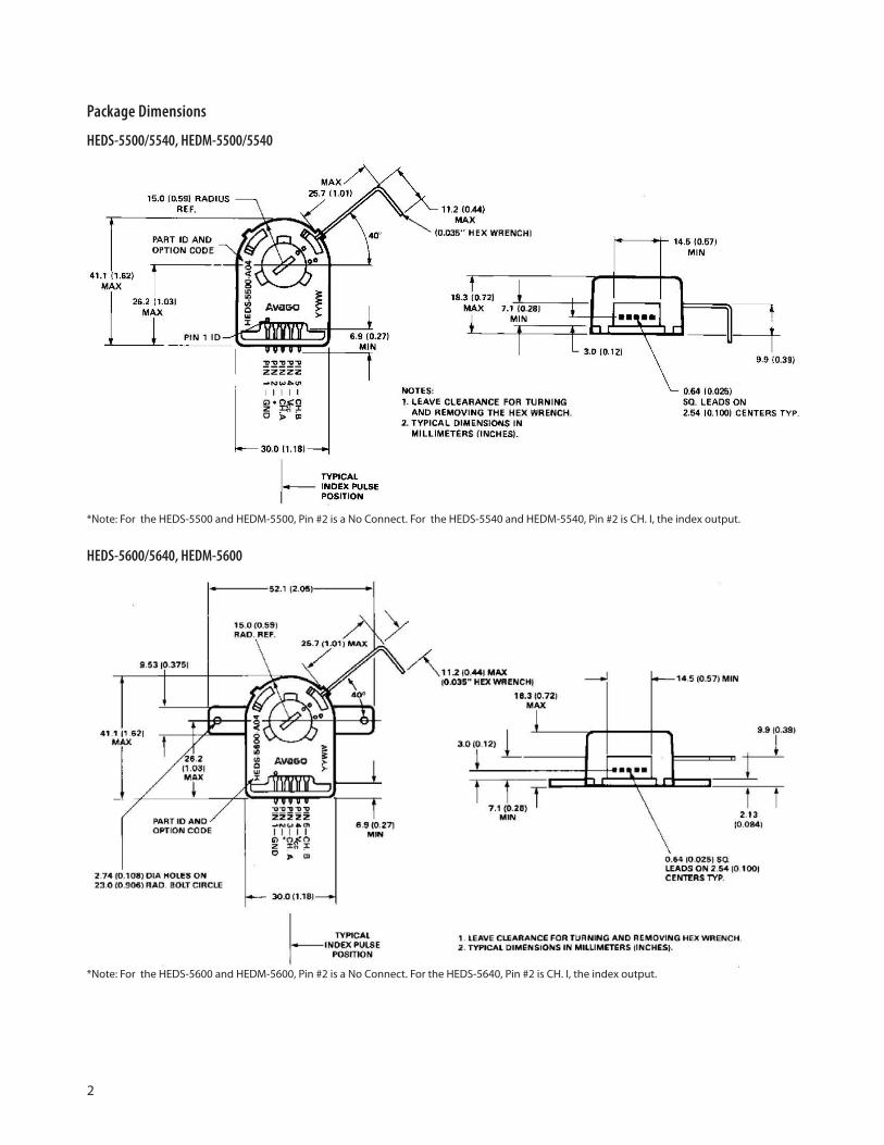
HEDS-5600/5640, HEDM-5600
*Note: For the HEDS-5600 and HEDM-5600, Pin #2 is a No Connect. For the HEDS-5640, Pin #2 is CH. I, the index output.
3
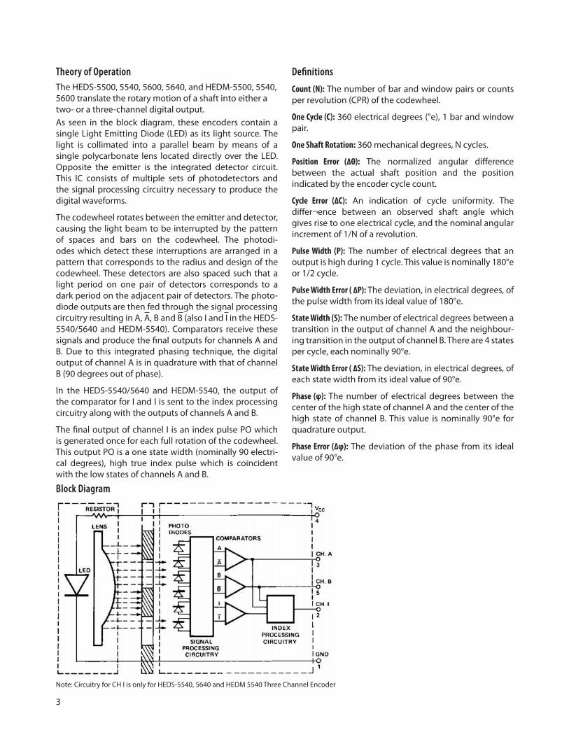
Theory of Operation The HEDS-5500, 5540, 5600, 5640, and HEDM-5500, 5540, 5600 translate the rotary motion of a shaft into either a two- or a three-channel digital output. As seen in the block diagram, these encoders contain a single Light Emitting Diode (LED) as its light source. The light is collimated into a parallel beam by means of a single polycarbonate lens located directly over the LED. Opposite the emitter is the integrated detector circuit. This IC consists of multiple sets of photodetectors and the signal processing circuitry necessary to produce the digital waveforms.
The codewheel rotates between the emitter and detector, causing the light beam to be interrupted by the pattern of spaces and bars on the codewheel. The photodi-odes which detect these interruptions are arranged in a pattern that corresponds to the radius and design of the codewheel. These detectors are also spaced such that a light period on one pair of detectors corresponds to a dark period on the adjacent pair of detectors. The photo-diode outputs are then fed through the signal processing circuitry resulting in A, A, B and B (also I and I in the HEDS-5540/5640 and HEDM-5540). Comparators receive these signals and produce the final outputs for channels A and B. Due to this integrated phasing technique, the digital output of channel A is in quadrature with that of channel B (90 degrees out of phase).
In the HEDS-5540/5640 and HEDM-5540, the output of the comparator for I and I is sent to the index processing circuitry along with the outputs of channels A and B.
The final output of channel I is an index pulse PO which is generated once for each full rotation of the codewheel. This output PO is a one state width (nominally 90 electri-cal degrees), high true index pulse which is coincident with the low states of channels A and B.
Block Diagram
Definitions
Count (N): The number of bar and window pairs or counts per revolution (CPR) of the codewheel.
One Cycle (C): 360 electrical degrees (°e), 1 bar and window pair.
One Shaft Rotation: 360 mechanical degrees, N cycles.
Position Error (∆Θ): The normalized angular difference between the actual shaft position and the position indicated by the encoder cycle count.
Cycle Error (∆C): An indication of cycle uniformity. The differ¬ence between an observed shaft angle which gives rise to one electrical cycle, and the nominal angular increment of 1/N of a revolution.
Pulse Width (P): The number of electrical degrees that an output is high during 1 cycle. This value is nominally 180°e or 1/2 cycle.
Pulse Width Error ( ∆P): The deviation, in electrical degrees, of the pulse width from its ideal value of 180°e.
State Width (S): The number of electrical degrees between a transition in the output of channel A and the neighbour-ing transition in the output of channel B. There are 4 states per cycle, each nominally 90°e.
State Width Error ( ∆S): The deviation, in electrical degrees, of each state width from its ideal value of 90°e.
Phase (φ): The number of electrical degrees between the center of the high state of channel A and the center of the high state of channel B. This value is nominally 90°e for quadrature output.
Phase Error (∆φ): The deviation of the phase from its ideal value of 90°e.
Note: Circuitry for CH I is only for HEDS-5540, 5640 and HEDM 5540 Three Channel Encoder
4
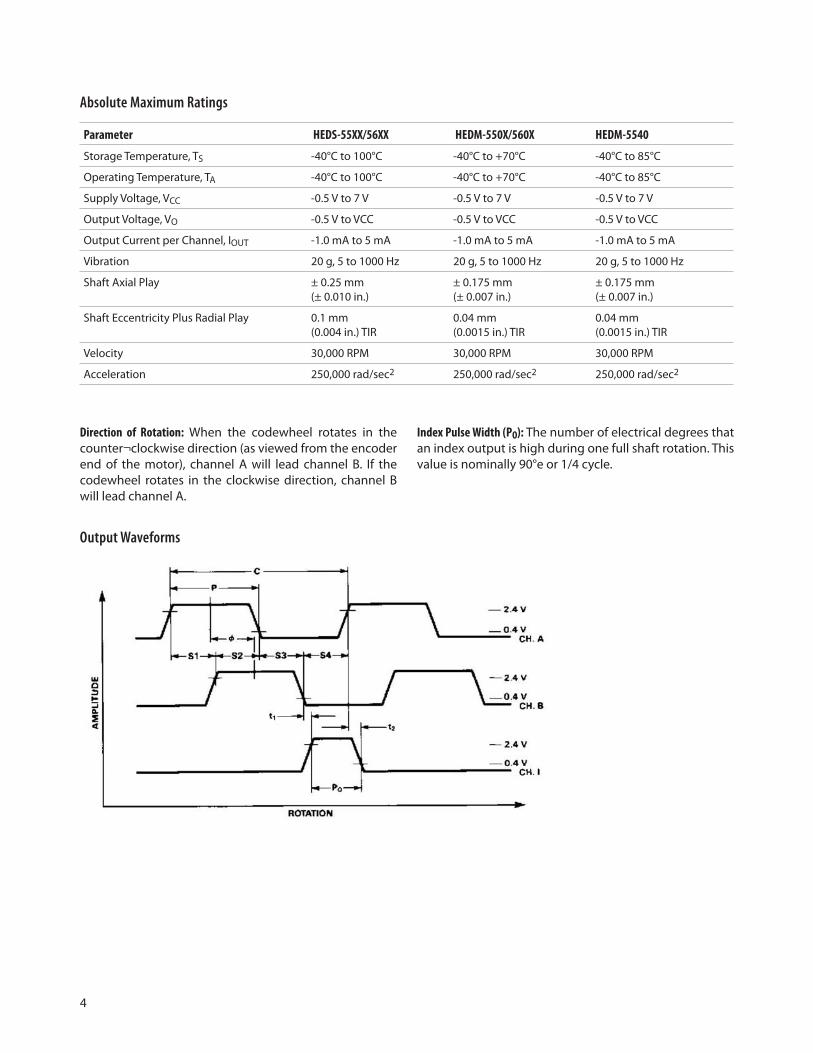
Direction of Rotation: When the codewheel rotates in the counter¬clockwise direction (as viewed from the encoder end of the motor), channel A will lead channel B. If the codewheel rotates in the clockwise direction, channel B will lead channel A.
Absolute Maximum Ratings
Parameter HEDS-55XX/56XX HEDM-550X/560X HEDM-5540
Storage Temperature, TS -40°C to 100°C -40°C to +70°C -40°C to 85°C
Operating Temperature, TA -40°C to 100°C -40°C to +70°C -40°C to 85°C
Supply Voltage, VCC -0.5 V to 7 V -0.5 V to 7 V -0.5 V to 7 V
Output Voltage, VO -0.5 V to VCC -0.5 V to VCC -0.5 V to VCC
Output Current per Channel, IOUT -1.0 mA to 5 mA -1.0 mA to 5 mA -1.0 mA to 5 mA
Vibration 20 g, 5 to 1000 Hz 20 g, 5 to 1000 Hz 20 g, 5 to 1000 Hz
Shaft Axial Play ± 0.25 mm(± 0.010 in.)
± 0.175 mm (± 0.007 in.)
± 0.175 mm (± 0.007 in.)
Shaft Eccentricity Plus Radial Play 0.1 mm (0.004 in.) TIR
0.04 mm (0.0015 in.) TIR
0.04 mm (0.0015 in.) TIR
Velocity 30,000 RPM 30,000 RPM 30,000 RPM
Acceleration 250,000 rad/sec2 250,000 rad/sec2 250,000 rad/sec2
Index Pulse Width (PO): The number of electrical degrees that an index output is high during one full shaft rotation. This value is nominally 90°e or 1/4 cycle.
Output Waveforms

5
Recommended Operating Conditions Parameter Sym. Min. Typ. Max. Units Notes
Temperature HEDS Series TA -40 100 °C
Temperature HEDM Series 5500/5600 TA -40 70 °C non-condensing atmosphere 5540 TA -40 85 °C
Supply Voltage VCC 4.5 5.0 5.5 Volts Ripple < 100 mVp-p
Load Capacitance CL 100 pF 2.7 kΩ pull-up
Count Frequency f 100 kHz Velocity (rpm) x N/60
Shaft Perpendicularity Plus Axial Play (HEDS Series)
± 0.25 (±0.010)
mm (in.)
6.9 mm (0.27 in.) from mounting surface
Shaft Eccentricity Plus Radial Play (HEDS Series)
0.04 (0.0015)
mm (in.) TIR
6.9 mm (0.27 in.) from mounting surface
Shaft Perpendicularity Plus Axial Play (HEDM Series)
± 0.175 (±0.007)
mm (in.)
6.9 mm (0.27 in.) from mounting surface
Shaft Eccentricity Plus Radial Play(HEDM Series)
0.04 (0.0015)
mm (in.) TIR
6.9 mm (0.27 in.) from mounting surface
Note: The module performance is guaranteed to 100 kHz but can operate at higher frequencies. 2.7 kΩ pull-up resistors required for HEDS-5540/5640 and HEDM-5540.
Encoding Characteristics
Part No. Description Sym. Min Typ.* Max. Units
HEDS-5500HEDS-5600(Two Channel)
Pulse Width ErrorLogic State Width ErrorPhase ErrorPosition ErrorCycle Error
∆P∆S∆Φ∆Θ∆C
752103
454520405.5
°e°e°emin. of arc°e
HEDM-5500HEDM-5600(Two Channel)
Pulse Width ErrorLogic State Width ErrorPhase ErrorPosition ErrorCycle Error
∆P∆S∆Φ∆Θ∆C
10102103
454515407.5
°e°e°emin. of arc°e
HEDS-5540HEDS-5640(Three Channel)
Pulse Width ErrorLogic State Width ErrorPhase ErrorPosition ErrorCycle ErrorIndex Pulse Width
∆P∆S∆Φ∆Θ∆CPo 55
55210390
453515405.5125
°e°e°emin. of arc°e°e
CH.I rise after CH.A or CH. B fall
-40°C to +100°C t1 -300 100 250 ns
CH.I fall after CH.A or CH. B rise
-40°C to +100°C t2 70 150 1000 ns
HEDM-5540(Three Channel)
Pulse Width ErrorLogic State Width ErrorPhase ErrorPosition ErrorCycle ErrorIndex Pulse Width
∆P∆S∆Φ∆Θ∆CPo 50
1010210690
4545154012130
°e°e°emin. of arc°e°e
CH.I rise after CH.A or CH. B fall
-40°C to + 85°C t1 200 1000 1500 ns
CH.I fall after CH.A or CH. B rise
-40°C to + 85°C t2 0 300 1500 ns
Note: See Mechanical Characteristics for mounting tolerances. *Typical values specified at VCC = 5.0 V and 25°C.

6
Electrical Characteristics
Electrical Characteristic over Recommended Operating Range
Part No. Parameter Sym. Min Typ.* Max. Units Notes
HEDS-5500HEDS-5600
Supply CurrentHigh Level Output VoltageLow Level Output Voltage
ICCVOHVOL
2.417 40
0.4
mAVV
IOH = -40μA maxIOL= 3.2mA
Rise TimeFall Time
trtf
20050
nsns
CL= 25 pFRL = 11 kΩ pull-up
HEDS-5540HEDS-5640HEDM-5500HEDM-5600
Supply CurrentHigh Level Output VoltageLow Level Output Voltage
ICCVOHVOL
302.4
57 85
0.4
mAVV
IOH = -200μA maxIOL= 3.86mA
Rise TimeFall Time
trtf
18040
nsns
CL= 25 pFRL = 2.7 kΩ pull-up
HEDM-5500HEDM-5600
Supply CurrentHigh Level Output VoltageLow Level Output Voltage
ICCVOHVOL
302.4
57 85
0.4
mAVV
IOH = -40μA maxIOL= 3.86mA
Rise TimeFall Time
trtf
18040
nsns
CL= 25 pFRL = 3.2 kΩ pull-up
HEDM-5540 Supply CurrentHigh Level Output VoltageLow Level Output Voltage
ICCVOHVOL
302.4
57 85
0.4
mAVV
IOH = -200μA maxIOL= 3.86mA
Rise TimeFall Time
trtf
20080
nsns
CL= 25 pFRL = 2.7 kΩ pull-up
* Typical values specified at VCC = 5.0V and 25ºC
7
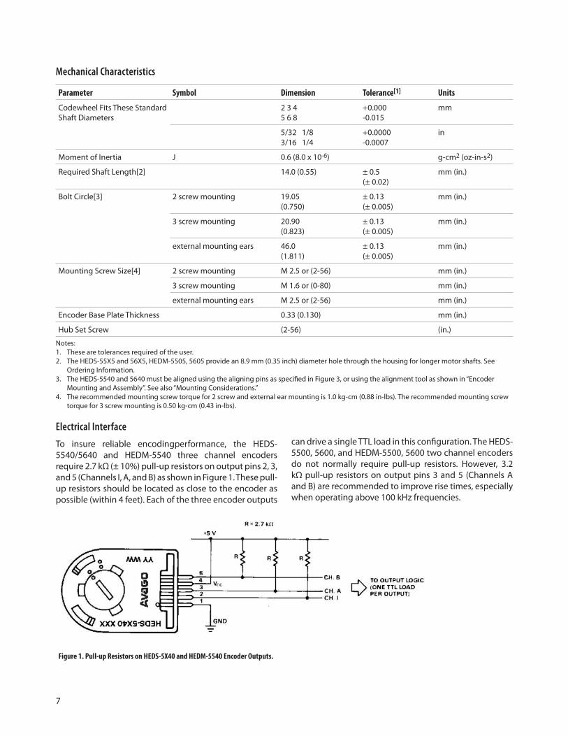
Electrical Interface
To insure reliable encodingperformance, the HEDS-5540/5640 and HEDM-5540 three channel encoders require 2.7 kΩ (± 10%) pull-up resistors on output pins 2, 3, and 5 (Channels I, A, and B) as shown in Figure 1. These pull-up resistors should be located as close to the encoder as possible (within 4 feet). Each of the three encoder outputs
Figure 1. Pull-up Resistors on HEDS-5X40 and HEDM-5540 Encoder Outputs.
can drive a single TTL load in this configuration. The HEDS-5500, 5600, and HEDM-5500, 5600 two channel encoders do not normally require pull-up resistors. However, 3.2 kΩ pull-up resistors on output pins 3 and 5 (Channels A and B) are recommended to improve rise times, especially when operating above 100 kHz frequencies.
Mechanical Characteristics
Parameter Symbol Dimension Tolerance[1] Units
Codewheel Fits These Standard Shaft Diameters
2 3 4 5 6 8
+0.000-0.015
mm
5/32 1/8 3/16 1/4
+0.0000 -0.0007
in
Moment of Inertia J 0.6 (8.0 x 10⁻⁶) g-cm2 (oz-in-s2)
Required Shaft Length[2] 14.0 (0.55) ± 0.5(± 0.02)
mm (in.)
Bolt Circle[3] 2 screw mounting 19.05 (0.750)
± 0.13(± 0.005)
mm (in.)
3 screw mounting 20.90 (0.823)
± 0.13(± 0.005)
mm (in.)
external mounting ears 46.0 (1.811)
± 0.13(± 0.005)
mm (in.)
Mounting Screw Size[4] 2 screw mounting M 2.5 or (2-56) mm (in.)
3 screw mounting M 1.6 or (0-80) mm (in.)
external mounting ears M 2.5 or (2-56) mm (in.)
Encoder Base Plate Thickness 0.33 (0.130) mm (in.)
Hub Set Screw (2-56) (in.)
Notes:1. These are tolerances required of the user. 2. The HEDS-55X5 and 56X5, HEDM-5505, 5605 provide an 8.9 mm (0.35 inch) diameter hole through the housing for longer motor shafts. See
Ordering Information. 3. The HEDS-5540 and 5640 must be aligned using the aligning pins as specified in Figure 3, or using the alignment tool as shown in “Encoder
Mounting and Assembly”. See also “Mounting Considerations.” 4. The recommended mounting screw torque for 2 screw and external ear mounting is 1.0 kg-cm (0.88 in-lbs). The recommended mounting screw
torque for 3 screw mounting is 0.50 kg-cm (0.43 in-lbs).
8
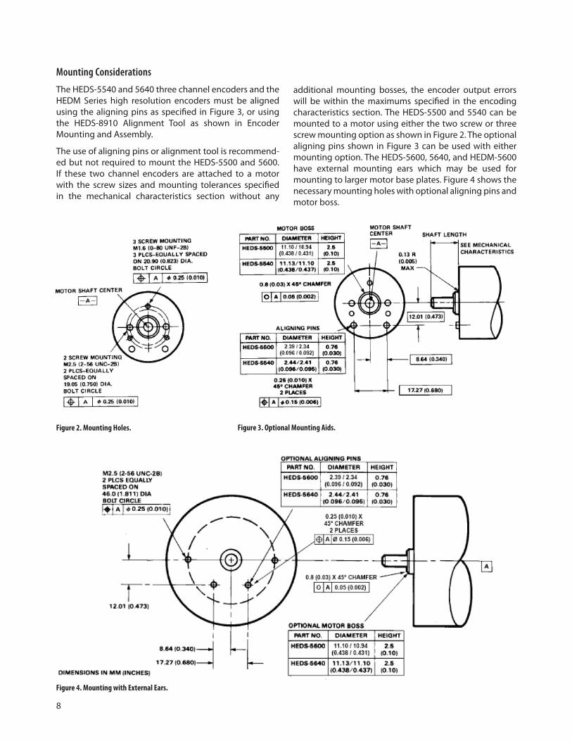
Figure 2. Mounting Holes. Figure 3. Optional Mounting Aids.
Figure 4. Mounting with External Ears.
Mounting Considerations
The HEDS-5540 and 5640 three channel encoders and the HEDM Series high resolution encoders must be aligned using the aligning pins as specified in Figure 3, or using the HEDS-8910 Alignment Tool as shown in Encoder Mounting and Assembly.
The use of aligning pins or alignment tool is recommend-ed but not required to mount the HEDS-5500 and 5600. If these two channel encoders are attached to a motor with the screw sizes and mounting tolerances specified in the mechanical characteristics section without any
additional mounting bosses, the encoder output errors will be within the maximums specified in the encoding characteristics section. The HEDS-5500 and 5540 can be mounted to a motor using either the two screw or three screw mounting option as shown in Figure 2. The optional aligning pins shown in Figure 3 can be used with either mounting option. The HEDS-5600, 5640, and HEDM-5600 have external mounting ears which may be used for mounting to larger motor base plates. Figure 4 shows the necessary mounting holes with optional aligning pins and motor boss.
9
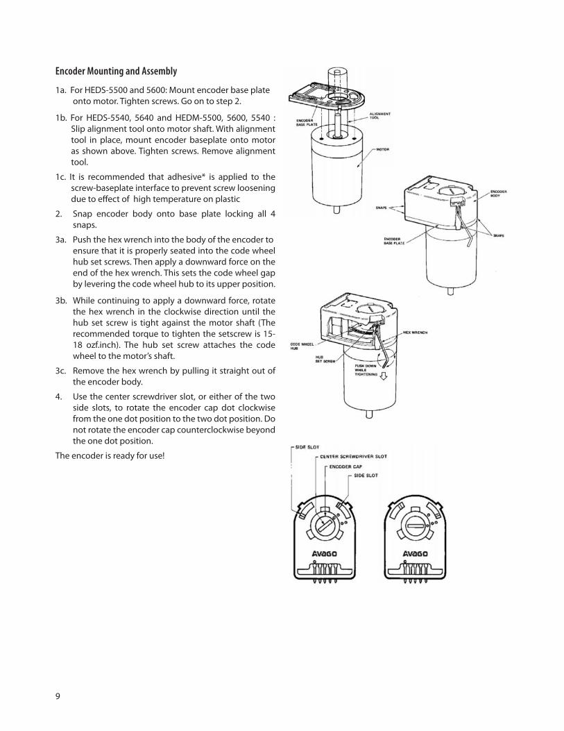
Encoder Mounting and Assembly
1a. For HEDS-5500 and 5600: Mount encoder base plate onto motor. Tighten screws. Go on to step 2.
1b. For HEDS-5540, 5640 and HEDM-5500, 5600, 5540 : Slip alignment tool onto motor shaft. With alignment tool in place, mount encoder baseplate onto motor as shown above. Tighten screws. Remove alignment tool.
1c. It is recommended that adhesive* is applied to the screw-baseplate interface to prevent screw loosening due to effect of high temperature on plastic
2. Snap encoder body onto base plate locking all 4 snaps.
3a. Push the hex wrench into the body of the encoder to ensure that it is properly seated into the code wheel hub set screws. Then apply a downward force on the end of the hex wrench. This sets the code wheel gap by levering the code wheel hub to its upper position.
3b. While continuing to apply a downward force, rotate the hex wrench in the clockwise direction until the hub set screw is tight against the motor shaft (The recommended torque to tighten the setscrew is 15-18 ozf.inch). The hub set screw attaches the code wheel to the motor’s shaft.
3c. Remove the hex wrench by pulling it straight out of the encoder body.
4. Use the center screwdriver slot, or either of the two side slots, to rotate the encoder cap dot clockwise from the one dot position to the two dot position. Do not rotate the encoder cap counterclockwise beyond the one dot position.
The encoder is ready for use!
10
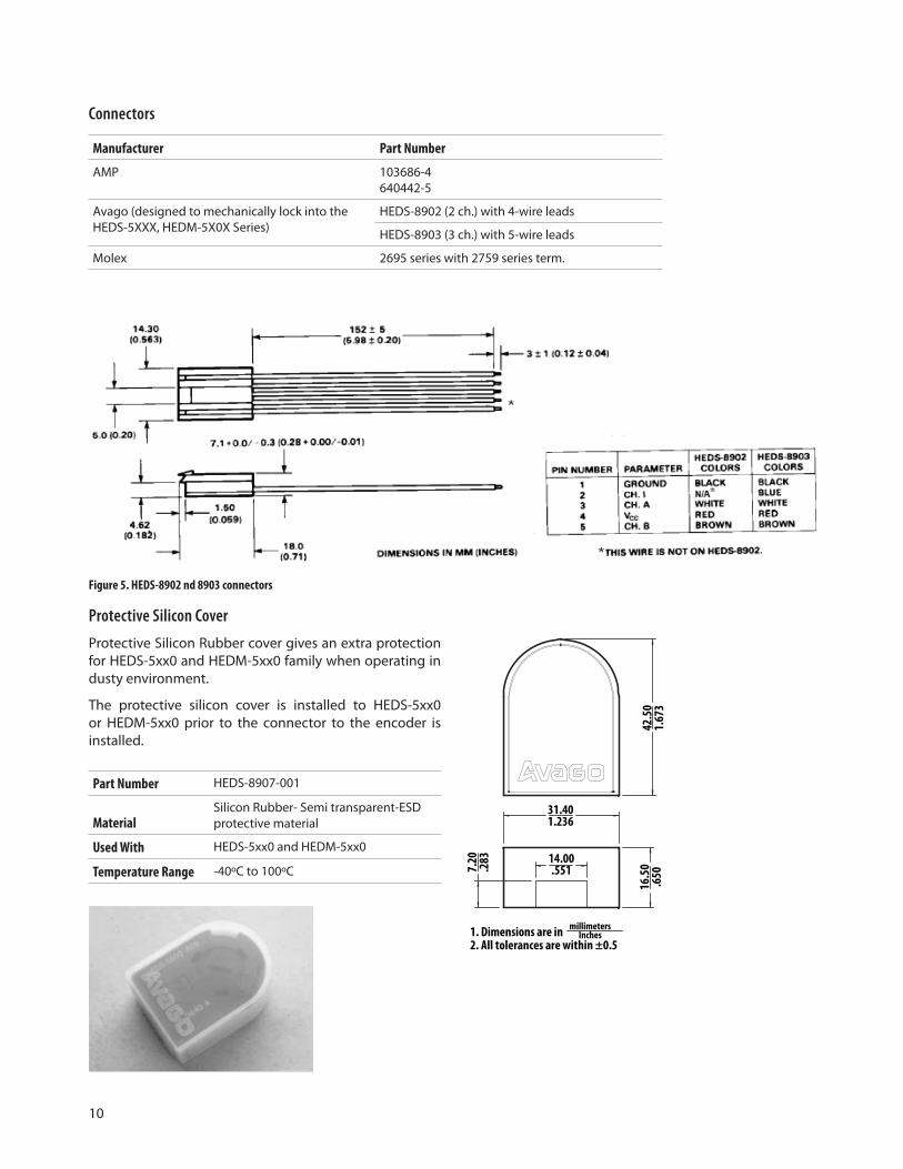
Connectors
Manufacturer Part Number
AMP 103686-4 640442-5
Avago (designed to mechanically lock into the HEDS-5XXX, HEDM-5X0X Series)
HEDS-8902 (2 ch.) with 4-wire leads
HEDS-8903 (3 ch.) with 5-wire leads
Molex 2695 series with 2759 series term.
Figure 5. HEDS-8902 nd 8903 connectors
Protective Silicon Cover
Protective Silicon Rubber cover gives an extra protection for HEDS-5xx0 and HEDM-5xx0 family when operating in dusty environment.
The protective silicon cover is installed to HEDS-5xx0 or HEDM-5xx0 prior to the connector to the encoder is installed.
Part Number HEDS-8907-001
MaterialSilicon Rubber- Semi transparent-ESD protective material
Used With HEDS-5xx0 and HEDM-5xx0
Temperature Range -40ºC to 100ºC
42.50
1.673
31.401.236
14.00.551
16.50
.650
7.20
.283
1. Dimensions are in2. All tolerances are within ±0.5
millimetersInches
11
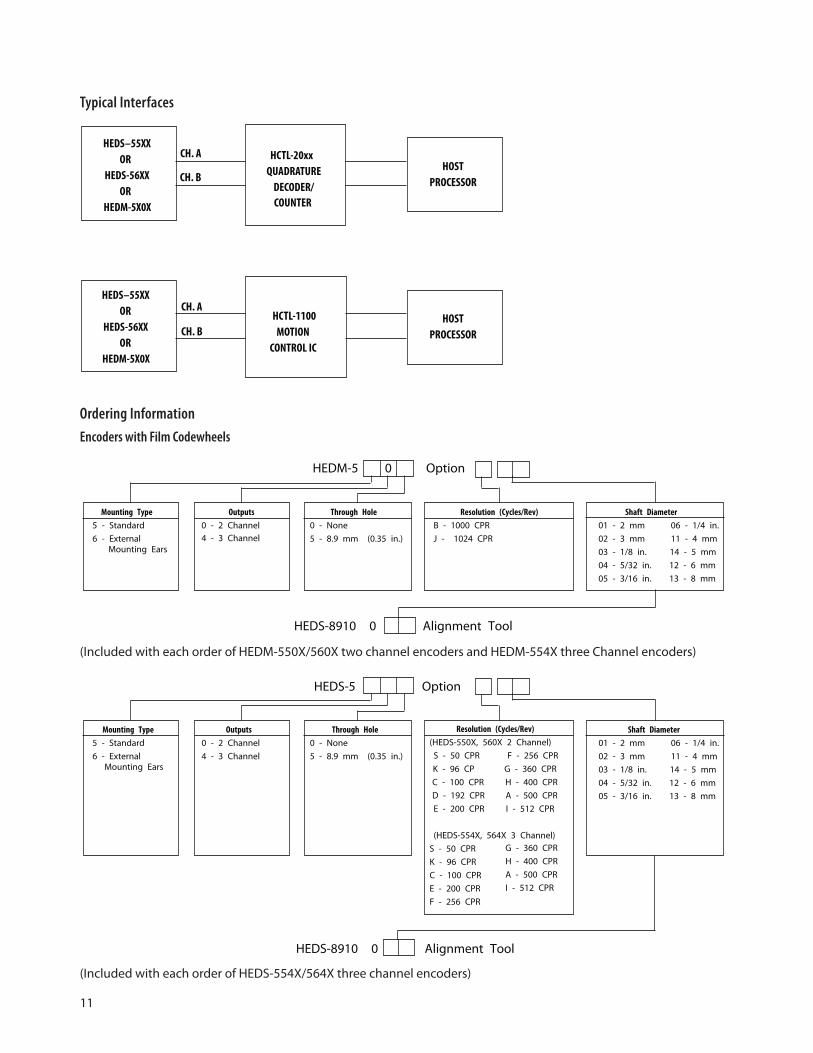
Shaft Diameter
01 - 2 mm 06 - 1/4 in.
02 - 3 mm 11 - 4 mm
03 - 1/8 in. 14 - 5 mm
04 - 5/32 in. 12 - 6 mm
05 - 3/16 in. 13 - 8 mm
Mounting Type
5 - Standard
6 - ExternalMounting Ears
Resolution (Cycles/Rev)
B - 1000 CPR
J - 1024 CPR
Through Hole
0 - None
5 - 8.9 mm (0.35 in.)
Outputs
0 - 2 Channel
HEDS-8910 0 Alignment Tool
HEDM-5 0 Option
HEDS-5 Option
Shaft Diameter
01 - 2 mm 06 - 1/4 in.
02 - 3 mm 11 - 4 mm
03 - 1/8 in. 14 - 5 mm
04 - 5/32 in. 12 - 6 mm
05 - 3/16 in. 13 - 8 mm
Mounting Type
5 - Standard
6 - ExternalMounting Ears
Through Hole
0 - None
5 - 8.9 mm (0.35 in.)
Outputs
0 - 2 Channel
4 - 3 Channel
4 - 3 Channel
HEDS-8910 0 Alignment Tool
Resolution (Cycles/Rev)
(HEDS-550X, 560X 2 Channel)
S - 50 CPR F - 256 CPR
K - 96 CP G - 360 CPR
C - 100 CPR H - 400 CPR
D - 192 CPR A - 500 CPR
E - 200 CPR I - 512 CPR
(HEDS-554X, 564X 3 Channel)
S - 50 CPR
K - 96 CPR
C - 100 CPR
E - 200 CPR
F - 256 CPR
G - 360 CPR
H - 400 CPR
A - 500 CPR
I - 512 CPR
Typical Interfaces
HOST
PROCESSOR
HEDS–55XX
OR
HEDS-56XX
OR
HEDM-5X0X
HCTL-20xx
QUADRATURE
DECODER/
COUNTER
CH. A
CH. B
HOST
PROCESSORCH. B
CH. AHEDS–55XX
OR
HEDS-56XX
OR
HEDM-5X0X
HCTL-1100
MOTION
CONTROL IC
Ordering Information
Encoders with Film Codewheels
(Included with each order of HEDM-550X/560X two channel encoders and HEDM-554X three Channel encoders)
(Included with each order of HEDS-554X/564X three channel encoders)
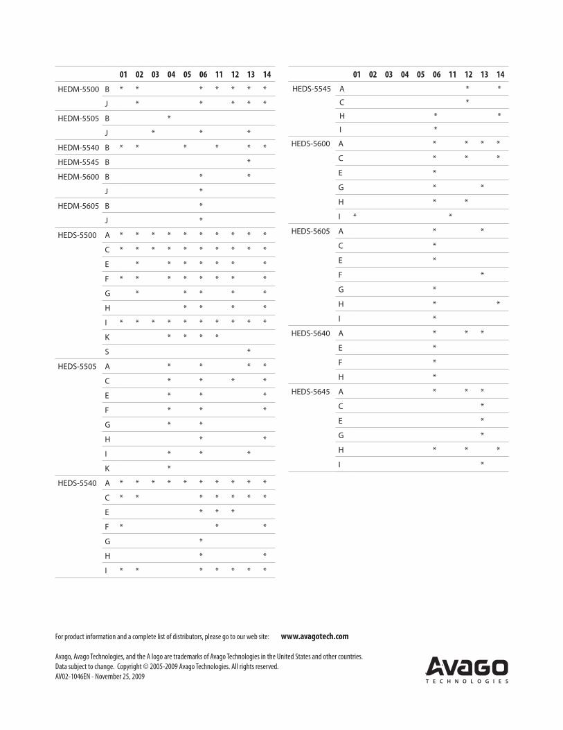
01 02 03 04 05 06 11 12 13 14
HEDM-5500 B * * * * * * *
J * * * * *
HEDM-5505 B *
J * * *
HEDM-5540 B * * * * * *
HEDM-5545 B *
HEDM-5600 B * *
J *
HEDM-5605 B *
J *
HEDS-5500 A * * * * * * * * * *
C * * * * * * * * * *
E * * * * * * *
F * * * * * * * *
G * * * * *
H * * * *
I * * * * * * * * * *
K * * * *
S *
HEDS-5505 A * * * *
C * * * *
E * * *
F * * *
G * *
H * *
I * * *
K *
HEDS-5540 A * * * * * * * * * *
C * * * * * * *
E * * *
F * * *
G *
H * *
I * * * * * * *
01 02 03 04 05 06 11 12 13 14
HEDS-5545 A * *
C *
H * *
I *
HEDS-5600 A * * * *
C * * *
E *
G * *
H * *
I * *
HEDS-5605 A * *
C *
E *
F *
G *
H * *
I *
HEDS-5640 A * * *
E *
F *
H *
HEDS-5645 A * * *
C *
E *
G *
H * * *
I *
For product information and a complete list of distributors, please go to our web site: www.avagotech.com
Avago, Avago Technologies, and the A logo are trademarks of Avago Technologies in the United States and other countries.
Data subject to change. Copyright © 2005-2009 Avago Technologies. All rights reserved.
AV02-1046EN - November 25, 2009